Increasing urbanization is creating pressure to manage housing, utilities and infrastructure holistically. Hence the concept of digital twins. Digital twins enable the integrated operation and maintenance of any geospatial asset to meet the increased demand for efficient and intelligent transportation systems, the green expansion of urban areas and sustainable infrastructure.
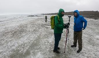
Traditional GNSS or optical measurement instruments no longer suffice to capture all the necessary information in a timely manner and with the right levels of detail. Integrating technological advances — GNSS, inertial systems, lidar sensors and 360° spherical imagery — into a single mobile-mapping system has greatly increased the ability to produce complete 3D models with high accuracy and precision. Mobile mapping also directly reduces workload, lowers project costs, simplifies data use, and provides reality-based design.
Mobile mapping surveys have been proven to be four to 10 times faster and three to seven times less expensive than traditional methods, delivering the required results up to three times faster. Integrated, multi-platform mobile-mapping solutions bridge the gap between the real world and the digital world for greater interoperability and accessibility of data in near real-time.
The high-accuracy and cross-platform design of CHC Navigation’s AlphaUni 900 lidar system provides an innovative solution for 3D spatio-temporal data acquisition, which is necessary for the digital transformation of the AEC industry.
Smart Cities
After developing for more than a decade, digital-twin technology is now a complex and comprehensive technical system to support the construction of new smart cities. It is an advanced model for the continuous innovation of urban development and a future form of modernization combining the virtual and real worlds. The creation of digital-twin cities brings to the forefront high-level topographic tools capable of providing comprehensive, multi-dimensional, large-scale, high-resolution data sets.
To illustrate typical digital-city projects, CHC Navigation conducted a proof-of-concept demonstration in the Jinshan District of Shanghai, which covers an area of about 600 square kilometers. This area has rich terrain features and characteristics typical of large modern cities, such as tall buildings, power lines, rivers and vegetation.
Versatile and easy-to-use platforms are essential for the democratization of lidar systems. Capturing 3D data with a single-platform lidar system can leave some areas blank in the point-cloud data. The AlphaUni900 lidar solution, with its multi-platform capability, can easily capture complete data from a UAV, car, backpack or unmanned surface vessel (USV) and provide a sophisticated and comprehensive 3D model. The AlphaUni 900 integrates seamlessly with real buildings, provides exterior and interior mapping, and dramatically changes the way high-precision data is collected.
The derived 3D models can be easily merged and correlated with social or economic spatial data, for example from building-integrated internet of things (IoT) and cloud computing data. As a result, complex operations can be optimized in real time, potential problems can be anticipated, and planned maintenance can be implemented to ensure the sustainability of urbanization projects over their entire lifespan, all in a fully connected model.
Affordable, user-friendly solutions for capturing and processing airborne lidar data and imagery have triggered a strong adoption of UAV technology in the AEC industry. For CHC Navigation, 2021 was marked by the huge success of the AlphaAir 450, a breakthrough in 3D UAV mapping technology. With its ease of use, high accuracy and affordability, the AA450 expands the scope of lidar surveying to non-professional users in geospatial reality-capture applications and to those who have never been able to afford such technology before.
A U.S. Secretary of Defense once predicted that navigation would eventually be based on inertial devices that were set at the factory, and then always knew where they were forever after. Recently published research has reported on steps in that direction. However, according to navigation expert Brad Parkinson, the outlook is not as bright as some might think.
RNT Foundation President Dana A. Goward recently discussed the issue with him.
Goward: Dr. Parkinson, you are well known for your contributions as the chief architect of the Global Positioning System. But you have more than a passing familiarity with inertial systems also, is that right?
Parkinson: I do. Long before I was involved in radio navigation, I was the chief analyst for all the U.S. Air Force testing of inertial navigation systems. I earned my masters degree in Doc Draper’s Inertial Lab at MIT in 1961. I am a major advocate and defender of inertial systems. I also have in-depth understanding of their limitations.
Goward: Have you been following the recent media coverage about advances with inertial systems?
Parkinson: I enjoy reading about these advances in physics devices. At the same time, I am a little impatient with media articles that do not appreciate the differences between building a device that measures specific force (or senses rotation) and a working inertial navigation system.
Goward: What are some of the inherent limitations of these systems?
Parkinson: I find it interesting that some of the articles speculate they may be able to supplant GPS and other GNSS. There is no way an inertial navigation system, even with perfect gyros and force sensors, can provide its accurate position (say, better than 10 meters) after extended periods (hours to days). In fact, attaining better than 200 meters accuracy after a few hours will be very difficult in a moving vehicle.
Today, farmers require even greater accuracy from GPS. They routinely use GPS for row operations, with accuracies of a few centimeters. The economic value is indirectly measured by the farmer’s purchase of such equipment — the agriculture market for GPS equipment is well over a billion dollars a year. Thus, a general replacement for GPS must provide centimeter accuracies.
Goward: So, what is it about inertial systems that stands in the way of them becoming autonomous substitutes for GPS?
Parkinson: There are some very simple and fundamental reasons that inertial positioning systems cannot hope to deliver such capability.
First, force sensors are not accelerometers, because they cannot sense gravity. To find acceleration, one needs to add vector gravity to their outputs. But gravity, or g force, varies a lot at the micro-g levels, and the inaccuracies are fed to the double integration that produces position. Errors grow as time or time squared and, without outside reset, are essentially unbounded. The physics devices described in some of these articles are definitely instruments that Doc Draper described as “specific force sensors.”
What we loosely call g force, or just g, is actually the inverse of the reaction to maintain stationarity on Earth. G is defined to include the centrifugal force due to Earth’s rotation, which varies greatly as a function of latitude — the radius of the merry-go-round called Earth. Mountains and chasms affect the local g. Further, it is a vector quantity: its direction can change locally by many arc seconds. In other words, down does not generally point to Earth’s center. Gravity gradiometers might be of limited help, but they are very large and not made for dynamic environments.
In a nutshell, estimating acceleration requires calculating and adding gravity to the three-dimensional specific force sensor.
Second, to use these devices for extended navigation, coordinate frames would have to be defined and stable to milli-arc seconds. All instruments would have to have input axes and cross-axis sensitivity calibrated to corresponding levels. Generally, this problem is ignored in many lab projects.
Third, for inertial navigation sensors to work, they need to accurately know their initial position. Any initial velocity or position errors will grow as a function of time.
Fourth, the vertical position axis is inherently unstable and diverges exponentially.
Physicists have been enamored with instruments that can use atoms to sense specific force and rotation. While scientifically interesting, even if perfect they cannot overcome these challenges.
Goward: But there is still a role for inertial systems in navigation, isn’t there? How good are they, and what are some of the applications?
Parkinson: I suspect the best inertial systems of today (which are in nuclear submarines) can maintain an accuracy of about 0.1 nautical miles or about 200 meters for a few days. I am sure the real number is classified. These systems are very large, expensive and complicated. They rely on a very low acceleration environment and are periodically reset with GPS. Furthermore, they probably use gravity gradiometry to calculate the local variations in gravity to the first order. They do not calculate the vertical position, and use water density and knowledge of the local geoid to keep the vertical axis stable.
An aircraft with inertial can, to some extent, keep the vertical dimension errors bounded, provided it has knowledge from elsewhere of local sea-level barometer settings and by assuming adiabatic pressure variations.
I strongly support the inertial/GPS/directional antenna marriage for users who want assured PNT. Aviation is a good use case for this. Inexpensive inertial components (called micro-electromechanical systems, or MEMS) can improve the jamming resistance of the GPS receiver by 15 dB or more. This step alone can reduce the effective line-of-sight jammer denial area by more than 95%.
Goward: So, inertials can be a good part of the solution but are not necessarily the whole solution themselves.
Parkinson: Exactly. Despite what some media outlets might publish to lure in readers.
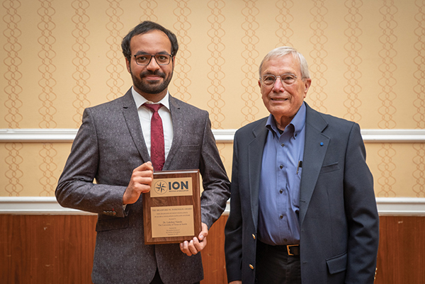
At the ION GNSS+ 2021 conference in St. Louis, Missouri, the annual meeting of the Satellite Division of the Institute of Navigation, Brad Parkinson bestowed Lakshay Narula with the division’s Bradford W. Parkinson Award for his Ph.D. thesis “Towards Secure & Robust PNT for Automated Systems” at the University of Texas at Austin. The award honors Parkinson, known as the “father of GPS,” for his leadership in establishing both GPS and the Satellite Division of the ION. Narula is now an applied scientist at Amazon Lab126 in Sunnyvale, California, where he researches robust navigation and state estimation methods for robots, from self-driving cars to aerospace applications. (Photo: ION)
While some tasks for AEC surveying are similar to other types of surveying — such as original ground surveying, creating site control and live monitoring — the biggest differences and challenges arise in data management, timeframes, communication and deliverables.
In AEC surveying, the project timeline is the primary factor driving everything, creating a different kind of pressure on the surveyor. As data experts and problem solvers, surveyors for AEC must quickly adapt to construction progress, as their survey knowledge can be needed on site at any point.
Information transfer challenges also exist — such as clearly communicating data to non-surveyors who perform measurement tasks — along with creating unique deliverables across construction stages. These include 3D terrain models with real-world coordinates for architects; fit-for-purpose computer-aided design and Industry Foundation Class models for machine operators and mechanical, electrical and plumbing installers or off-site fabricators; and progress reports for project owners.
Several AEC firms have opted to create their own inhouse survey teams. This allows greater control over the consistency and clarity in communication and deliverables, because they focus exclusively on surveying for AEC and are therefore familiar with its specific challenges.
The main challenge for the surveyor in AEC is sifting through and processing the data, assessing quality, understanding relevance, producing results and crafting deliverables to meet the clients’ needs.
An integrated total solution is important for AEC surveyors who must decide not only which technology to use, but how to process data from different technologies together. Our products fit within this integrated solution concept.
Leica Geosystems‘ automated total stations, multistations and GNSS blend innovation and traditional technology, such as the Leica GS18 I with tilt and visual positioning, enabling surveyors to measure more, faster.
For mass data collection, the Leica RTC360 3D laser scanner operates at two million points per second and contains visual inertial system (VIS) technology simplifying the registration process. The Leica BLK series combines intelligence and accessibility, including the BLK360 imaging laser scanner, the handheld BLK2GO, and the latest autonomous technology of the BLK2FLY and BLKARC.
Finally, our software connects surveyors to their sensors and data in the field with Leica Captivate and Leica Cyclone Field 360 and to the office with Leica Infinity and Leica Cyclone, extending to existing CAD software with the Leica CloudWorx suite of CAD plug-ins.
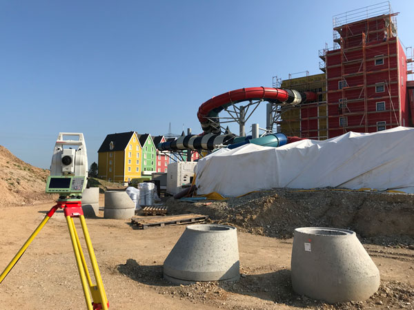
Bringing an Aqua Park to Life
One memorable success story was the use of our products for AEC survey tasks during construction of Germany’s biggest aqua park, Rulantica. The survey work was led by Saladin Keller of Keller planen + bauen. The project involved the creation and construction of a Nordic-themed water world featuring 25 attractions, including water slides, a wave pool and a lazy river.
Alongside all the typical surveying for AEC tasks — establishing site control, staking out pipes, and planning and staking the entire traffic infrastructure — Keller had the challenge of measuring and positioning the complex internal geometry. These tasks required skilled surveyors and a variety of survey tools, such as total stations, GNSS rovers, laser scanners and powerful processing software.
Operating within the AEC environment also meant that communication and flexibility were key to the success of the project. Keller needed to provide the right data to different trades and handle urgent maintenance requests requiring surveying skill, such as rebuilding parts and adjusting utilities.
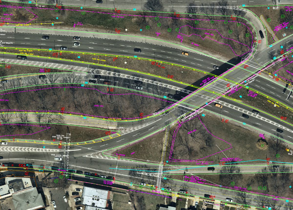
Nearmap aerial imagery is used as a basis for survey linework. Photo: Nearmap
With Congressional approval of $17 billion in infrastructure funding, the largest single allocation ever, the scramble to win contracts is about to get red hot and AEC firms are gearing up. In this very competitive game, top engineering firms are relying on their experience, technology, business acumen and ability to execute.
Advances in aerial mapping play a key role in how AEC firms pursue these contracts. Savvy firms have been using this technology for years. Rather than rely on lower resolution satellite imagery or local drone imagery, they use wide-area-coverage aerial maps to clearly display the detail needed to plan and execute.
Over the past decade, maps made using aerial photogrammetry have played an important role in the AEC space. Using high-performance cameras, fleets of planes capture hundreds of square miles per plane per day, provided that the weather is clear. The imagery is processed and made available to engineering companies within days of capture, allowing them to see very clear imagery.
AEC organizations use different forms of aerial maps to evaluate sites, improve their survey designs, and build and maintain infrastructure (roads, highways, bridges, tunnels, overpasses, rail, airports, housing, commercial building development, water resources, parks, pavement and more). Imagine you’re a state or local government that needs to build a bridge, or a developer who wants to contract with an engineering and construction firm to build affordable housing. Why travel to perform time-consuming site evaluations when you can meet with engineering teams in your office and review hundreds of potential sites instantly using current aerial photos that show change over time?
The engineering teams point out elevation changes, the presence and height of vegetation, neighboring communities, bodies of water, ponding and more. They easily navigate from one location to another as you discuss where the entrance to the community could be, how the road network might be configured, and the proximity to retail, schools and healthcare. Within minutes you measure risk, understand the landscape, make decisions, and begin to estimate the project costs. Your teams collaborate, discuss the pros and cons, measure distances and navigate across the terrain virtually.
Aerial mapping provides a competitive advantage for AEC companies to win their fair share of the infrastructure bill. It also gives governments and developers the confidence they need to make the right decisions. Typically, this involves looking at sites from all angles. The classic form of aerial mapping used by engineers is a top-down perspective. Increasingly, these organizations have used oblique imagery captured at an angled perspective, which shows height.
Artificial Intelligence and Aerial Photography
Starting a few years ago, 3D imagery and digital surface models began to allow engineers to navigate through the imagery and query it based on elevation. More recently, aerial mapping has leveraged artificial intelligence (AI) to classify properties and the landscape. Do you need to see nearby construction sites? AI applied to aerial photography can do that automatically. This rich set of data includes attributes such as tree overhang, roof condition, roof material, building footprints, vegetation height, surface material, swimming pools and even solar panels.
The blend of all these imagery types and AI into a single solution makes everything discoverable. Users can search by address, city, location or point of interest. They can visualize the imagery along with lat/long coordinates and quickly switch from top-down views to obliques to 3D. As they learn more about the landscape, they begin to turn on AI attributes, gaining deeper insights.
Sometimes, the analyses go even further. Engineering organizations export the imagery to tools of their choice from such companies as Autodesk, Esri or Bentley Systems, use field-collected ground control points to ensure that it is survey grade, then use it as a base layer for their designs. They even create marketing presentations and video content to help them win the business. Current high-resolution aerial maps have become a cornerstone of how these organizations operate.
This approach provides unique advantages for engineering firms. For example, they can combine geospatial and construction datasets in a common operating environment to reduce complexity, streamline communication, ensure that all stakeholders are up to date, and check their progress toward meeting contractual obligations.
Planners have current, contextual designs and models to make accurate decisions about planning and development activities. They can view asset locations and conditions to facilitate maintenance and upgrades, leverage aerial maps inside other platforms to improve work orders and reduce field visits, and ensure regulatory compliance.
Whether it’s improving highway safety, constructing ferry terminals, improving transportation systems, developing land or building a network of recreational trails, aerial imagery provides engineering and construction companies with a competitive advantage to win new business, improve client satisfaction and meet growth targets. With $17 billion on the line, sophisticated firms are finding a way to secure their fair share of the pie.
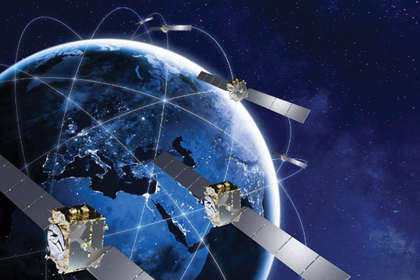
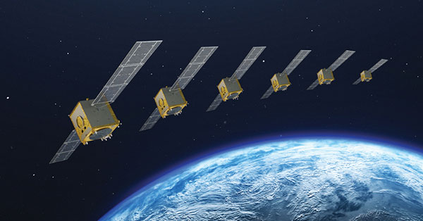
Galileo Second Generation Batch#1A satellites. (Image: ESA).
Successful European Cooperation
Galileo is Europe’s civil global satellite navigation constellation and a major success, being the world’s most precise satnav system and offering meter-scale accuracy to more than two billion users around the globe.
The signature of the Financial Framework Partnership Agreement (FFPA) on June 22, 2021, further strengthened effective cooperation between the European Commission (EC), the European Union Agency for the Space Program (EUSPA), and the European Space Agency (ESA) — key to successfully achieving a crucial EU Space Program component like Galileo in the current EU Multi Financial Framework (2021–2028).
The EC is the program manager, with EUSPA acting as the exploitation manager and ESA as the system development prime.
Stable Service Performance
Galileo continues to deliver excellent service performance every month in a safe, secure and seamless manner. Delivery of Galileo services is managed by EUSPA, as the Galileo service provider, with industrial partner SpaceOpal, the Galileo service operator prime contractor. The performance of Galileo services is independently monitored by the Galileo Reference Center (GRC) and regularly published on the GNSS Service Center (GSC) web portal at www.gsc-europa.eu — both agencies were developed by GMV. The security of the Galileo System is monitored by the Galileo Security Monitoring Centers (GSMC), operated by EUSPA.
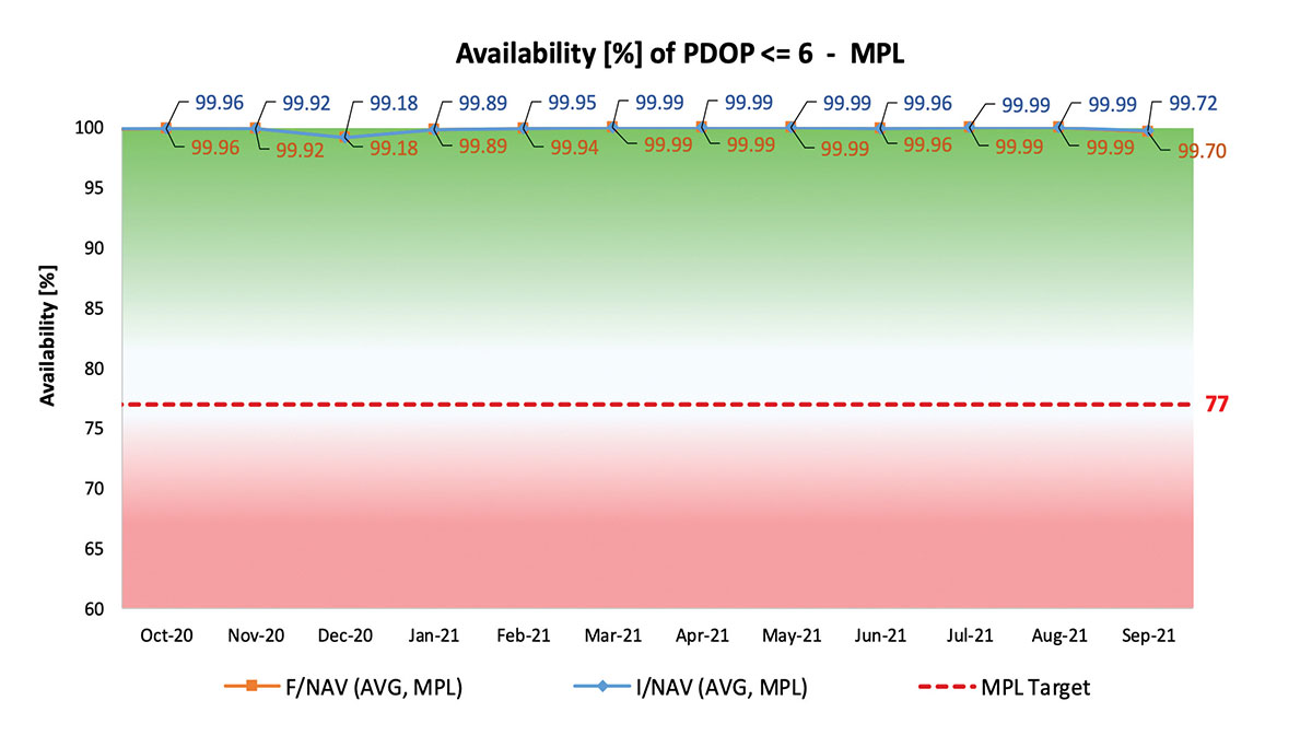
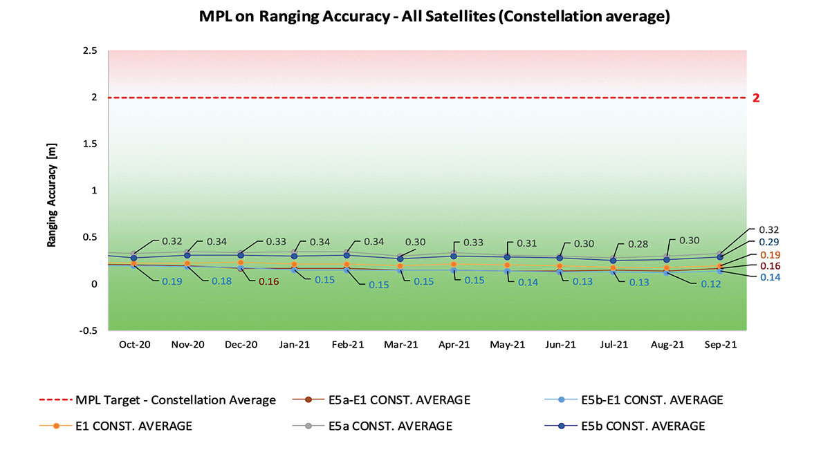
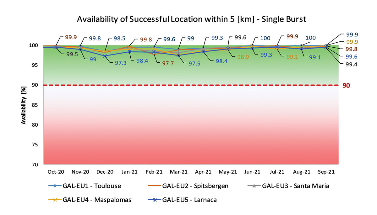
With 22 satellites in service, the open service is already delivering more than 99% availability of PDOP <= 6 worldwide. This, together with the excellent ranging accuracy, suggests that most Galileo dual-frequency users are typically experiencing positioning accuracy in the order of only 2 to 3 meters.
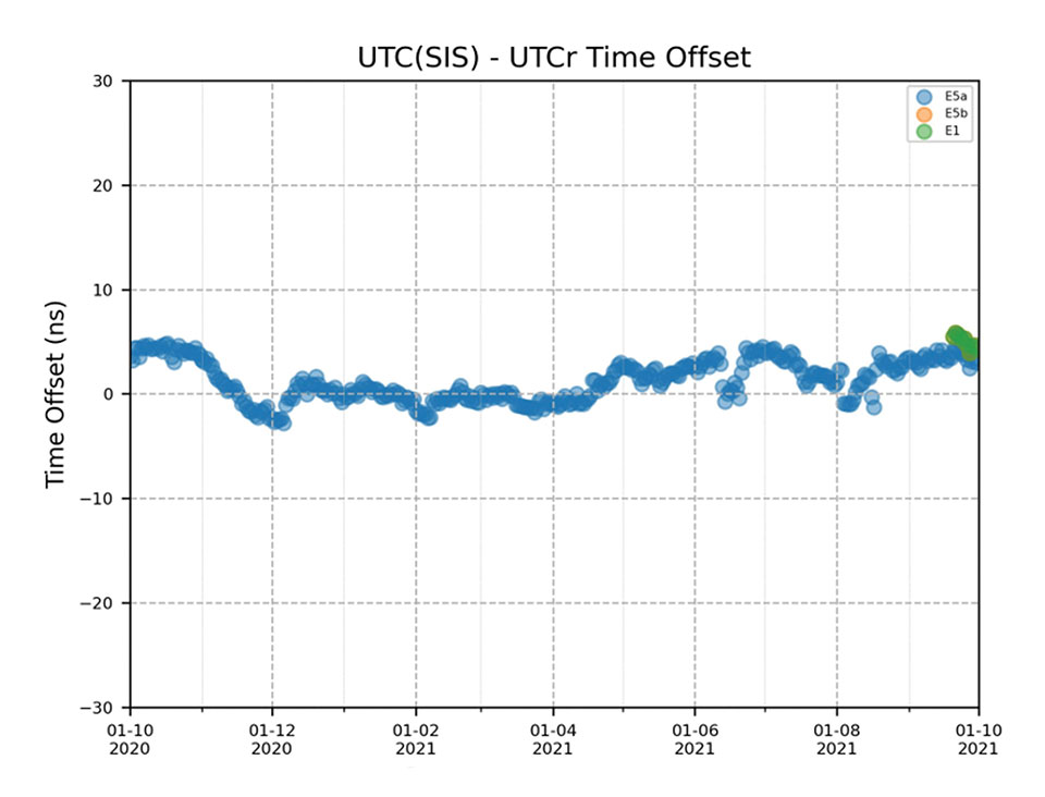
Timing users also continue to receive accurate (in the order of 5 ns) access to Galileo System Time, which they can trace to Universal Coordinated Time (UTC) through the corresponding offset parameters transmitted by the satellites.
The SAR/Galileo service, contributing to COSPAS/SARSAT, continues to deliver both the Forward Link Service (FLS) and the Return Link Service (RLS) with more than 99% availability, allowing users in distress not only to issue an alert and be located within a few minutes, but also be notified that the alert was successfully processed and rescue is on the way. The SAR/Galileo control center is located in Toulouse (France) and operated by CNES under the authority of EUSPA. The excellent performance of the service has been demonstrated both through several rescue exercises and real-life emergencies.
Performance of Galileo positioning services. (Credit: EUSPA)
Performance of Galileo positioning services. (Credit: EUSPA)
Galileo Launch 11
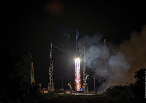
Soyuz launcher VS-26 lifted off from French Guiana with the first pair of Galileo Batch 3 satellites on Dec. 5, 2021, at 01:19 CET. This marks the 11th Galileo launch of operational satellites in 10 years: a decade of hard work by Europe’s Galileo partners and European industry. With these satellites, the robustness of the constellation has increased, guaranteeing a higher level of service.
Thanks to an upgrade of the Ground Control Segment, the Launch and Early Orbit Phase has been for the first time conducted directly from the Galileo Control Center, rather than requiring an external mission control site. This version of the ground segment increases overall reliability and cybersecurity and opens the way to significant expansion of the Galileo constellation, allowing command and control of up to 38 satellites. The development has been performed by an industrial consortium led by GMV, harnessing state-of-the-art technology using the latest solutions on the market.
Galileo launch 11 from Europe’s spaceport in French Guyana. (Photo: ESA)
On Route to Full Operational Capability
This year will pave the way toward Full Operational Capability of Galileo services.
Industrial prime contractor OHB Systems has nearly completed production of the additional 10 recurrent satellites belonging to Galileo Batch 3. Six of them are undergoing final acceptance testing at the ESA satellite test center, and the other four are under integration at the satellite prime facilities.
Preparation for Launch 12 has already started, with the satellites’ acceptance for a launch date planned in the first months of 2022, followed by Launch 13 in autumn. This is leading toward completion of the Galileo constellation, providing an increased availability of the Galileo signal in space for both GNSS and search-and-rescue users.
Performance of Galileo timing and search-and-rescue services. (Credit: EUSPA)
Performance of Galileo timing and search-and-rescue services. (Credit: EUSPA)
From 2023 onward, the remaining Batch 3 satellites will be launched with the new Ariane 62 launch vehicle, a variant of Ariane 6 with two strap-on solid boosters. The launcher is undergoing the final stages of development, led by prime contractor ArianeGroup.
The Galileo Ground Mission Segment will undergo a complete technological refresh, including hardware virtualization and porting of several million lines of code, performed by an industrial consortium led by Thales France. A series of improvements will be introduced to increase system resilience, including an extended mode of operation to improve service continuity and robustness.
Cybersecurity monitoring of all the ground assets will be introduced as an overlay to the current ground infrastructure. The upgrade will undergo a rigorous level of qualification testing followed by worldwide deployment in a seamless way in both Galileo control centers, in both Galileo security monitoring centers, and at all remote locations without affecting continuity of service.
The service facilities that contribute to the delivery of Galileo services (the European GNSS Service Center, the Galileo Reference Center, and the SAR data service providers) will also evolve to support not only the transition from Initial Services to Full Operational Capability, but also the early roll-out of service evolutions. In this regard, extensive work is ongoing to deliver an exciting set of improvements, some of which are already in development or testing, to reach the users in the year to come:
Improvements of the I/NAV signal to increase robustness and time-to-first-fix, while assuring full backward compatibility with legacy receivers.
OS Navigation Message Authentication (OS-NMA) to support applications that require trust in the authenticity of the data transmitted by the Galileo satellites (a public observation campaign was launched in November 2021 to engage stakeholders and collect their feedback before moving to the initial service provision).
An initial phase of the High Accuracy Service, delivering corrections in the Galileo E6 signal and over terrestrial network to allow users to perform precise point positioning over Europe; test signals were already transmitted with promising results.
A Search and Rescue Beacon Command Service complementing the SAR Return Link, providing improved capabilities to timely locate beacons under authorized emergency situations (such as the disappearance of Flight MH370 in the Indian Ocean in 2014).
A first implementation of an Emergency Warning Service over Europe, allowing the authorized national emergency-management authorities of the EU Member States to relay alert messages through Galileo signals, which can reach target areas even in case of disrupted terrestrial communications (such as due to floods or earthquakes).
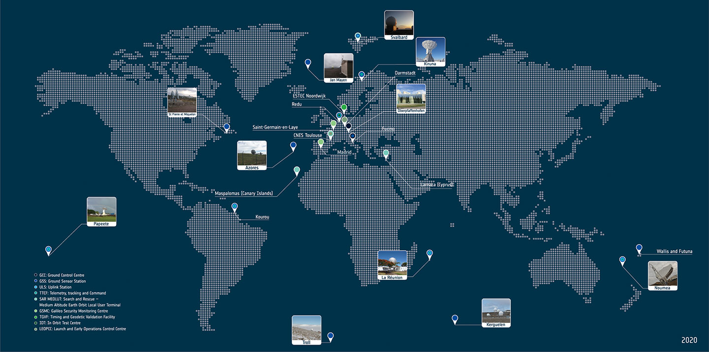
Galileo worldwide ground segment. (Credit: ESA)
Second Generation in the Making
The FFPA will bring Galileo to the next level with the development of the second generation, a further step forward with the use of many innovative technologies to guarantee the system’s unprecedented precision, robustness and flexibility.
In parallel to the completion of the first generation of Galileo, Europe has conducted in recent years preparation activities for the Second Generation (G2). Elaborating on market, user and exploitation needs collected by EUSPA, ESA identified a number of system evolution scenarios, which were discussed among relevant EU stakeholders to select the second-generation mission and services baseline to build the system infrastructure.
The evolution of Galileo capabilities will not only provide better services through advanced technical solutions identified by ESA, but will also ensure continuity of service and backward compatibility for
first-generation legacy users.
Two parallel contracts to develop and manufacture each of the six Galileo Second Generation Batch#1 satellites were kicked off in the first half of 2021 with Thales Alenia Space (Italy) and Airbus Defence & Space (Germany). The new G2 satellites will be constructed on a short time scale, with their first launch via Ariane-62 expected in less than four years, allowing them to commence operations in space as soon as possible. Both contracts have already undergone preliminary design reviews.
Development of the G2 satellites is supported by the Galileo Payload Test Bed, which provides an early proof-of-concept of the advanced G2 payload architecture. These satellites will provide, among others, the following key innovations:
Reconfigurable fully digital navigation payload.
Point-to-point connection between satellites by Inter-Satellite-Link for command and control and ranging functionalities.
Electric propulsion for orbit-raising capabilities.
Advanced jamming and spoofing protection mechanisms to safeguard Galileo signals.
System and Ground Segment definition studies, together with the associated technology pre-developments, have been performed, leading to the definition of the preliminary design and technical requirement baseline for the G2 system, a project involving most of Europe’s space industrial partners.
The G2 In-Orbit Validation Ground Segment and System Test Bed have been defined and relevant procurement procedures are ongoing, with these objectives:
G2 Batch#1 satellites launch and early orbit phase, in-orbit testing and enhanced legacy services provision.
G2 new capabilities in-orbit validation, including prototyping and validation of all the novel technologies that can exploit the full capabilities of the G2 Batch#1 satellites.
Galileo Second Generation Batch#1B satellites. (Image: ESA).
Definition activities for the G2 Initial Orbit Capability (IOC) are progressing well and are expected to converge in the first half of 2022, in order to establish the future roadmap for new G2 services provision in the years to come.
2022 will be a key year for the evolution of Galileo Second Generation activities, through the consolidation of the first batch of G2 satellite design and development activities and the start of development of associated G2G IOV Ground Segment and System Test Beds.
A bright future awaits Galileo, both through the completion of its Final Operational Capability and the start of evolution towards Galileo Second Generation.
Guerric Pont is Galileo Exploitation Program manager for the European Union Agency for the Space Program (EUSPA).
Marco Falcone is Galileo First Generation Project manager for the European Space Agency (ESA).
Miguel Manteiga Bautista is Galileo Second Generation Project manager for the European Space Agency (ESA).
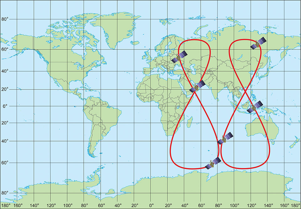
Figure 1. GLONASS high inclined space complex. (Image: Institute of Navigation Technology JSC)
The digital transformation of the global economy requires precise time synchronization and valid object position information. Global navigation satellite systems (GNSS) are the most accurate tool for such tasks.
This year will be 40th anniversary of the launch of the first GLONASS satellite, and we see that the quality of navigation services is driven by the characteristics of today’s satellite navigation signals.
The first fourth-generation Glonass-K2 #13L satellite is scheduled for launch in 2022. It will broadcast a full ensemble of navigation signals — both Frequency Division Multiple Access (FDMA) signals in the L1 and L2 bands and Code Division Multiple Access (CDMA) signals in the L1, L2 and L3 bands. This long-awaited launch will cap a 10-year effort and begin to provide a new platform by broadcasting all the CDMA signals through a single antenna array on the satellite’s geometric axis.
The FDMA antenna array is displaced by 0.9 m from this axis, but this arrangement is done on only two satellites. The next Glonass-K2 satellites, which will be launched beginning in 2024, will have a single antenna array for all navigation signals.
The final second-generation Glonass-M satellite, scheduled to be placed in orbit next year, will provide services by open FDMA signals in the traditional bands at 1.6 GHz and 1.25 GHz. This satellite will be the seventh Glonass-M vehicle able to broadcast GLONASS L3 CDMA signals. There are only two Glonass-K satellites broadcasting this signal now, but more satellites with such a signal will be activated by the end of testing of the GLONASS modernized ground control facility.
We expect the number of satellites able to provide this service to increase by two per year as we replace Glonass-M satellites with Glonass-K and Glonass-K2 satellites.
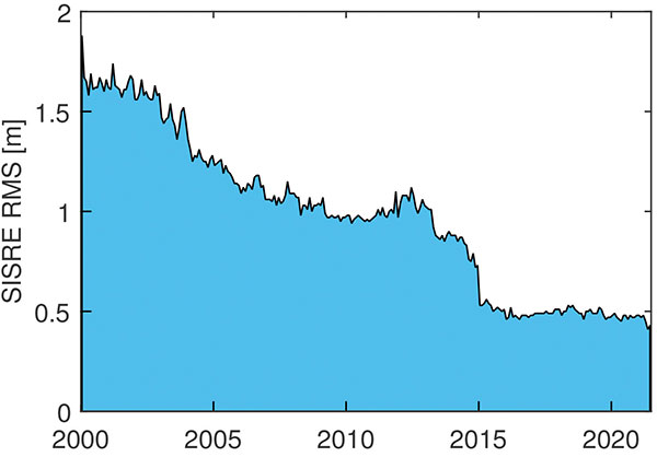
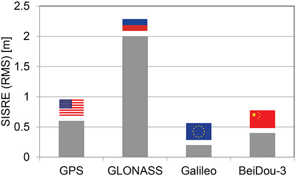
As of this writing, 15 satellites (62% of the constellation) are working past their guaranteed life times, limiting our ability to increase the system’s accuracy. For the last decade, the signal-in-space range error (SISRE) was 1.4 m, despite the fact that newly launched satellites provide a SISRE of about 0.8 m.
Glonass-K satellites will be launched to maintain the orbit constellation within the next three years, and the accuracy of their signals will be the same or even better. These satellites have a single antenna array for all three bands and could broadcast either FDMA or CDMA signals.
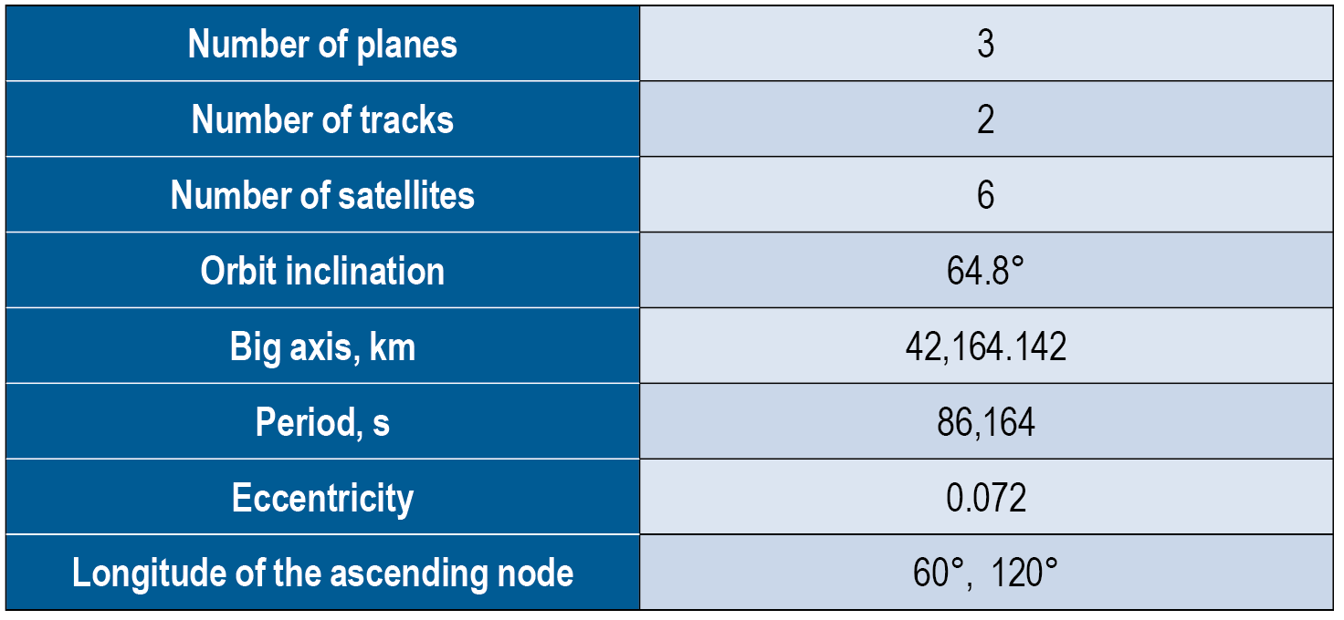
In 2022, the constellation orbits will increase to six satellites in three planes, as we aim to increase the navigation service accuracy and availability (FIGURE 1). See TABLE 1 for satellite orbit parameters. This constellation will make it possible to increase navigation accuracy in the Eastern Hemisphere by about 25% through decreasing the value of the geometric factor.
Additionally, this will greatly improve the availability of the GLONASS navigation service in difficult conditions, such as locations where current users can only receive navigation signals from satellites at least 25° above the horizon. New constellation satellites will be based on the Glonass-K platform, which has passed in-orbit qualification and proved it can provide SISRE at 0.3 m. The preliminary design proved that satellites on this platform could provide an in-orbit SISRE below 0.4 m with standard cesium on-board clocks. This signal-in-space accuracy level with valid ionospheric and tropospheric model data from the navigation signal will allow users to receive a position determination error below 2 m in the plane. Navigation services from these satellites will be provided by the CDMA signal in three frequency bands.
The new satellite will weigh about 1,000 kg and be launched into orbit from both Russian spaceports (northern Plesetsk and eastern Vostochny) by the highly reliable Soyuz-2 rocket. The first launch is scheduled for 2026.
One of GLONASS’ important tasks is to transmit the UTC (SU) national time scale to consumers. Over the past few years, significant results have been achieved in this area.
A complex of high-precision measuring instruments to compare the national coordinate timescale UTC (SU) with the GLONASS timescale was put into operation. These instruments include a transported quantum clock that provides timescale storage with an uncertainty of no more than 1 ns at an observation interval of one day, and with a transportation time of no more than 12 hours. It also provides duplex comparisons of timescales, comparing objects with the permissible uncertainty of ±1.5 ns.
Timescale storage complexes of secondary and working standards of time and frequency VET1-5 (Irkutsk), VET 1–19 (Novosibirsk), VET 1–7 (Khabarovsk) and RET1-1 (Petropavlovsk-Kamchatsky) were modernized and put into operation, providing an overall uncertainty of 3 · 10-15 and with a maximum permissible shift of the timescale of the complex relative to the national timescale UTC (SU) of ± 10 ns.
An optical ground-based frequency reference on cold strontium atoms was developed with an uncertainty of reproduction of the frequency unit and time of no more than 1 · 10-17 .
A keeper of time and frequency units was developed on the basis of a “fountain” of rubidium atoms having a frequency instability of no more than 2 · 10-16 for equipping the standards of time and frequency units and subsequent transmission of more accurate time-frequency information to precision ground and onboard equipment and GLONASS systems.
A developmental prototype of the national timescale storage complex of the Russian Federation was developed on the basis of a new generation of hydrogen keepers.
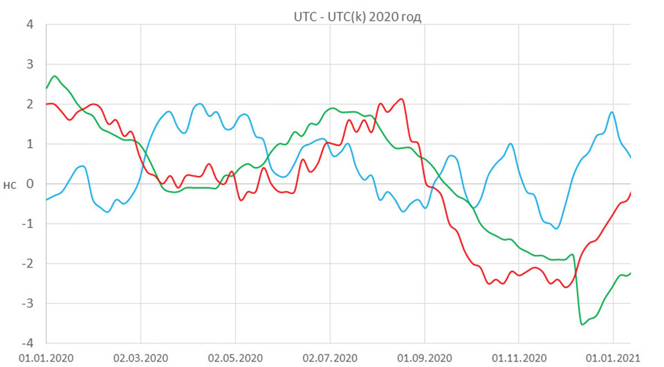
The application of the newly developed technical equipment made it possible to significantly reduce the maximum displacement of the national timescale relative to the International Coordinated Time Scale (UTC), which in 2020 was less than ± 3 ns (FIGURE 2). The UTC (SU) timescale ranks among the best national implementations of UTC, according to the International Bureau of Weights and Measures (BIMP).
Figure 2. Displacement of national timescales relative to Universal Coordinated Time (UTC). (Image: VNIIFTRI FSUE)
Many important events are coming for GLONASS users in 2022. They will improve the user characteristics and lay the foundation for further development of the system.
Sergey Karutin is general designer of the Russian GNSS program GLONASS.
Nicolay Testoedov is CEO of JSC Information Satellite Systems Reshetnev (ISS JSC), a Russian satellite manufacturing company.
Sergey Donchenko is general director of the Federal State Unitary Enterprise, Russian metrological institute of technical physics and radio engineering, VNIIFTRI FSUE.
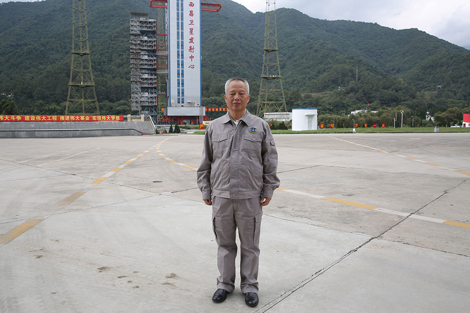
Yang Changfeng is BeiDou’s Chief Architect. (Photo: BeiDou Navigation Satellite System)
Construction of the BeiDou Navigation Satellite System (BDS-3) has been completed. The system was formally commissioned on July 31, 2020. In 2021, BDS continued to improve performance, expand applications and deepen cooperation, and has achieved sustained, stable and rapid development.
System Performance and Services
Currently, 45 BDS satellites are operational in orbit — 15 BDS-2 satellites and 30 BDS-3 satellites jointly provide seven types of services to users. Specifically, for the entire planet, the system provides three services:
Positioning, navigation and timing (PNT).
Global short-message communication.
International search-and-rescue (SAR) services.
For the Asia-Pacific region, the system provides four additional services:
Satellite-based augmentation.
Ground-based augmentation.
Precise point positioning.
Regional short-message communication services.
The system has been operating continuously and stably since commissioning, with the average value of satellite availability better than 0.99 and the average value of satellite continuity better than 0.999.
PNT Service. As actually measured by the International GNSS Monitoring and Assessment System (iGMAS), the global horizontal positioning accuracy is about 1.52 meters, the vertical positioning accuracy is about 2.64 meters (B1C signal single frequency, 95% confidence), the velocity measurement accuracy is better than 0.1 m/s, and timing accuracy is better than 20 nanoseconds. The performance is better in the Asia-Pacific region.
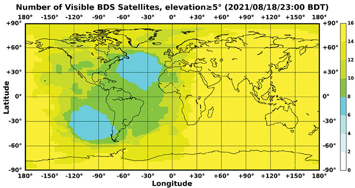
FIGURE 1 shows the number of visible BDS satellites worldwide at BDT 00:00 on Nov. 18, 2021. Among them, the number of visible BDS satellites exceeds 20 in some areas of the Asia-Pacific region.
Figure 1. Number of visible BDS satellites, elevation ≥5° (2021/11/18/00:00 BDT). (CREDIT: www.csno-tarc.cn)
Global Short Message Communication Service. Trial service is provided through 14 medium-Earth-orbit (MEO) satellites for authorized users and low-orbit satellites, with a maximum single-message length of 560 bits, equivalent to about 40 Chinese characters.
Search-and-Rescue Service. A COSPAS/SARSAT-compliant MEOSAR service is provided by six payloads deployed on six MEO satellites. A B2b signal-based Return Link Service (RLS) is provided through 24 MEO and three IGSO satellites, which have completed testing and verification and are in the process of coordination within the framework of COSPAS-SARSAT.
Satellite-Based Augmentation Service. China’s Civil Aviation Administration is organizing satellite-ground integrated test and evaluation, and the positioning accuracy, alarm time, integrity risk and other indicators meet the requirements.
Ground-Based Augmentation Service. Real-time centimeter-level and post-processing millimeter-level services are provided for industrial and public users, based on the regional network reference stations built in China.
Precise Point Positioning Service. PPP signals are broadcast by three GEO satellites. The measured horizontal positioning accuracy is 0.24 m, the vertical positioning accuracy is 0.41 m (95% confidence), and the convergence time is less than 20 minutes.
Regional Short Message Communication Service. The short-message communication function has been tested and verified for integration into public mobile phones; large-scale application is planned.
Development of the Applications Industry
Large-scale applications of BDS have entered a critical stage of liberalization, industrialization and internationalization. The overall output value of China’s satellite navigation and location-based service industry continued to grow in 2020, up to 403.3 billion yuan (US$63.2 billion), which is about 16.9% more than its value in 2019. In terms of BDS-3-enabled basic products, an industrial chain is gradually maturing, comprised of BDS/GNSS basic chips, modules, boards, antennas and other components.
The certification and testing system of basic BDS products has been established and implemented. BDS is already supported by most mainstream chips. BDS is increasingly being integrated into the daily life of the general public. It is becoming the standard configuration for positioning functions of smartphones and other mass-market products.
Smartphone manufacturers such as Xiaomi, Huawei, Apple and Samsung already support BDS. In the first three quarters of 2021, among all types of smartphones applying for online access in China, 72.3% supported positioning function based on BDS, accounting for 93.5% of the total sales volume. The BDS ground-based augmentation function has been introduced into smartphones to achieve high-precision positioning at the 1-meter level; lane-level navigation is being piloted in several cities in China.
In terms of industrial applications, BDS has fully served multiple industries including transportation, public security, disaster relief, agriculture, forestry, animal husbandry and fishing. It has accelerated the integration into electricity, finance, communications and other infrastructure. In particular, in the fight against COVID-19 through scientific and technological approaches, BDS-based precise positioning has facilitated the efficient supply and circulation of anti-epidemic materials.
BDS-based solutions for land rights determination, precision agriculture and smart ports have served the economic and social development of countries in Asia, Eastern Europe and Africa, and BDS-based products have been applied in more than half of the world’s countries and regions.
International Cooperation
BDS has always adhered to the development concepts of openness, cooperation and resource sharing; actively carried out practical international exchanges and cooperation; and contributed to China’s peaceful use of outer space.
Bilaterally, the Eighth Meeting of the China-Russia Project Committee on Major Strategic Cooperation in Satellite Navigation was held in October 2021. Both sides jointly formulated and signed the Roadmap for Cooperation in the Field of Satellite Navigation from 2021 to 2025, providing planning and guidance for China-Russia satellite navigation cooperation in the next five years. Also, China’s Satellite Navigation Office signed a memorandum of understanding on satellite navigation cooperation with the National Committee on Space Activities of the Republic of Argentina and the South African National Space Agency, and formally established a regular cooperation mechanism.
BDS is gradually being integrated into international standards, and is steadily promoting ratification by international standards bodies, including in the civil aviation, maritime, SAR, mobile communications and electrotechnical fields. Several international standards supporting BDS have been released. The Chinese government has drafted a letter of commitment to the International Civil Aviation Organization (ICAO), stating that BDS will provide basic services free of charge to civil aviation users around the world. The International Association of Marine Aids to Navigation and Lighthouse Authorities (IALA) has officially issued a standard that ratifies BDSBAS, so that global marine users can carry out applications based on it. The Third Generation Partnership Project has started the standardization of BDS-3’s B2a and B3I signals. In the detection standard for Indicating Radio Beacon Locator of the Global Maritime Distress and Safety System issued by the International Electrotechnical Commission, BDS receivers and BDS-based SAR services will be supported.
The Chinese government is steadily advancing the rule of law, attaching great importance to and comprehensively promoting the rule of law for satellite navigation. A legal system on BDS has been formed, consisting of national policies, industrial and local policies and regulations, and more. The legislative process of the Satellite Navigation Regulations of the People’s Republic of China has been actively promoted to ensure the healthy, rapid and sustainable development of the satellite industry. In May 2021, China issued a development report on the rule of law of BDS.
Follow-Up Plan
In the future, on the one hand BDS will ensure stable operation, while on the other hand it will focus on the development of backup satellites, and complete the production, state optimization and ground testing of backup satellites. Backup BDS-3 satellites with better performance will be launched as needed to further improve the reliability of the constellation. By adhering to the development concept of “BDS is developed by China, dedicated to the world and aiming to be first class,” carrying forward the BDS spirit of the new era of “independent innovation, open integration, unity of all, pursuit of excellence,” BDS will serve the world and benefit all humankind.
Number of BDS-3 satellites in orbit: 30
Signals broadcast: B1I, B3I, B1C, B2a, and B2b
Yang Changfeng is chief architect of the BeiDou Navigation Satellite System and a Chinese Academy of Engineering academician.
By Francesco Ardizzon, Nicola Laurenti, Carlo Sarto and Giovanni Gamba
To ensure the authenticity of the Galileo navigation messages, the Open Service navigation message authentication (OSNMA) mechanism requires a loose synchronization between the receiver clock and the system time.
To ensure the authenticity and the integrity of the transmitted messages, the Timed Efficient Stream Loss-tolerant Authentication (TESLA) protocol for broadcast authentication requires a loose time synchronization between the transmitter and the receiver — that is, an upper bound to the time offset between their clocks. In the context of the TESLA-based Open Service navigation message authentication (OSNMA) protocol, it is customary to assume that:
On the system side, the transmission is synchronous because the satellites are equipped with high-precision atomic clocks, the drift of which is assumed negligible with respect to those at the receiver side.
At the receiver side, commercial clocks can be found that are less accurate and less stable, which accounts for the substantial time mismatch between the transmitter and the receiver clocks accumulating over time.
To limit the impact of such mismatch on OSNMA operation, it is envisioned that clocks for authenticated tachographs onboard vehicles, such as the ones that will be employed for the position authenticated tachograph for OSNMA launch (PATROL) project, are reset and precisely realigned to system time in periodic workshop visits. However, the clock mismatch must satisfy the OSNMA constraint at all times between successive workshop resets, in the “holdover” period, and through all possible operating conditions, to ensure constant authenticity of the navigation message.
In other contexts, this task is performed by such means as network synchronization protocols.
However, we are considering a scenario where, during holdover, we cannot rely on other sources, such as an internet connection or other devices to synchronize with the reference time to assure the authenticity of our time reference and, consequently, of the PVT solution. We also cannot trust any signal received during the holdover period, thus we should not use the PVT solution to synchronize the clock.
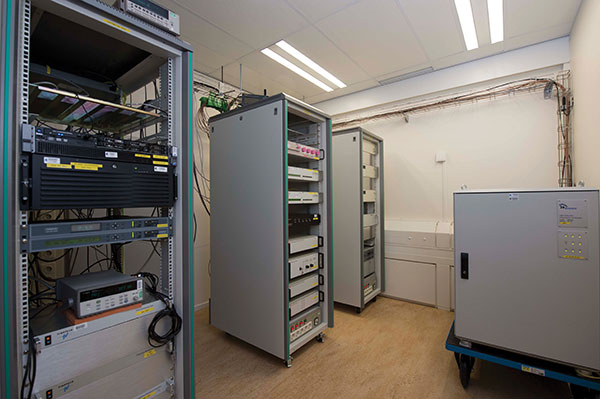
Here, we have two goals. First, investigate the causes of the misalignment and frequency deviation in clock generators commonly found on the market for GNSS receivers. Second, relate the clock specification parameters, taken directly from the real-time clock (RTC) device datasheets, the holdover period, and the OSNMA misalignment constraints.
Atomic clocks at ESTEC’s Navigation Laboratory in The Netherlands independently validate Galileo timing performance. (Photo: ESA)
Frequency Accuracy and Stability
Two metrics are usually employed to evaluate the performance of an oscillator.
Clock frequency accuracy is the normalized difference between the frequency output and its nominal value, f0.
Clock frequency stability is the normalized instantaneous frequency deviation from its local mean.
Although devices are characterized in terms of their stability, we are interested in measuring their accuracy y(t)ΔF(t)⁄f0, where ΔF(t) is the instantaneous frequency deviation from f0 at time t. The calibration performed during each workshop reset brings the residual misalignment to a negligible value called phase calibration error. On the other hand, we will later discuss the residual frequency deviation, due to the frequency calibration error.
The loose time synchronization requirement TL states that the authenticity of the navigation message received at time t is guaranteed if |ΔT(t)|≤TL, at every t during the holdover period.
Finally, we can relate accuracy and misalignment using the bound
(1)
which allows us to upper bound the clock misalignment at any time t in terms of the frequency accuracy along the whole interval elapsed from the last calibration time t0.
Accuracy Loss for Receiver Clocks
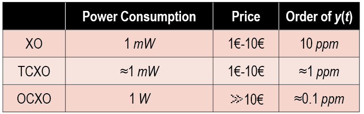
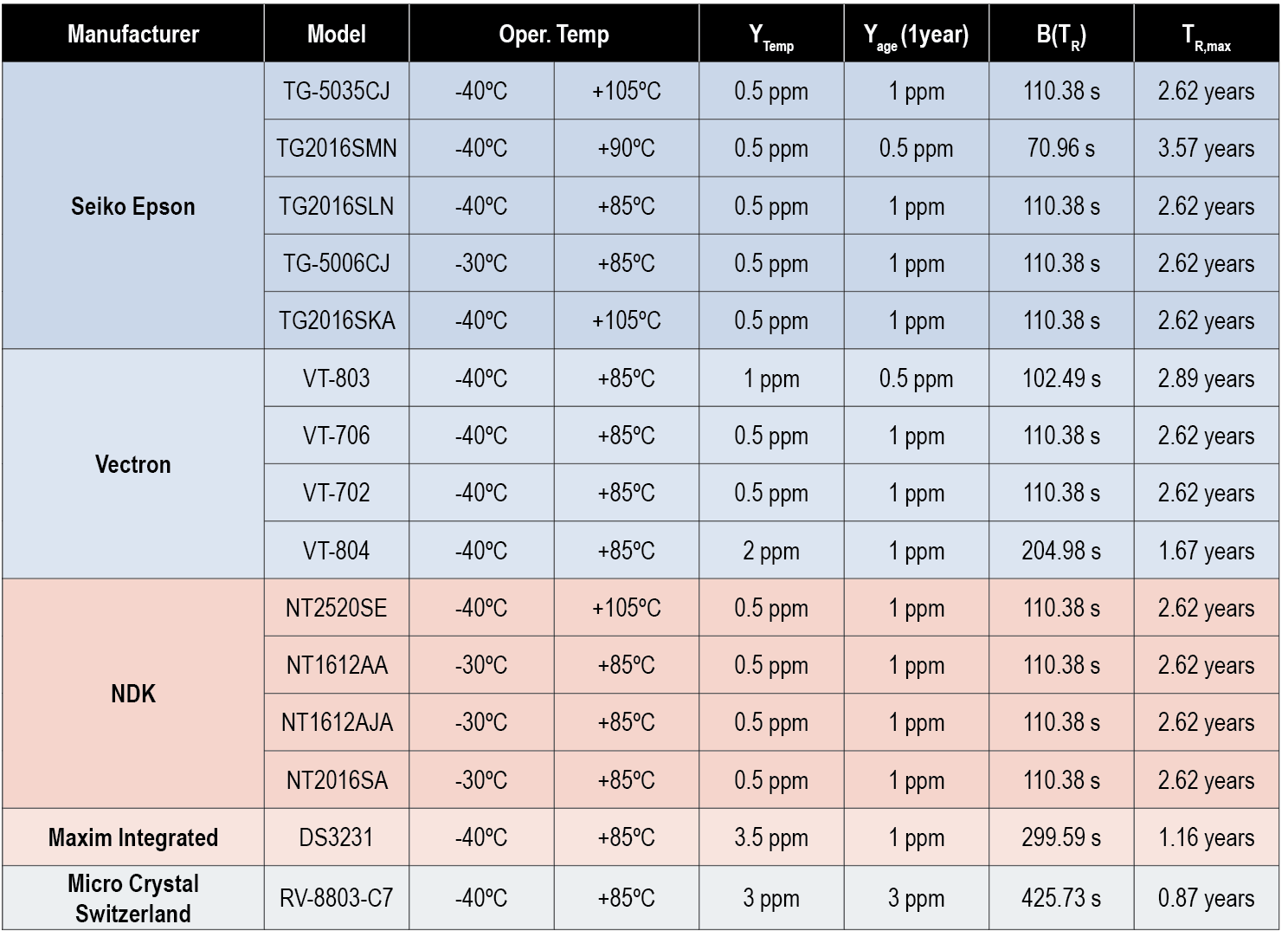
Thanks to their affordable price and wide temperature operating conditions, quartz crystal oscillators are used for clock generation in GNSS receivers (see TABLE 1). We distinguish among simple, temperature-controlled crystal oscillators (TCXOs) and oven-controlled crystal oscillators (OCXOs). GNSS receivers typically employ TXCOs because they offer the best trade-off in terms of power consumption, price and typical accuracy.
Table 1. Summary of the main quartz crystal oscillator characteristics.
Sources of Frequency Accuracy Loss. Quartz crystals are piezoelectric materials, therefore any additional stresses and environmental changes generate an additional voltage, decreasing the clock stability. In the automotive scenario, the main sources of accuracy loss are temperature changes, long-term aging, and the residual calibration frequency offset, while the impact of accelerations, vibrations, gravity variation and supply voltage oscillation can safely be neglected as they result in changes of a few parts per billion.
Currently, no analytic relationship is known between frequency accuracy and temperature for TCXOs (or OCXOs). Therefore, as reported in datasheets, the inaccuracy induced by the temperature changes is bounded by a constant value Ytemp across the whole operating temperature range. This yields a bound on the clock misalignment that increases linearly with the time from the last calibration.
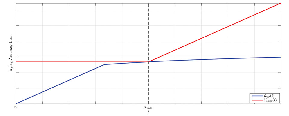
Long-term aging has significant impacts on the clock frequency accuracy and may affect the device even when it is not used for a long time (see Figure 1). A critical aspect of this effect is that it is time-variant, with the accuracy loss increasing over time.
Figure 1. Graphical representation of the model for aging accuracy loss: upper-bound (red) versus estimated model (blue). (Image: R. Filler and J. Vig)
However, datasheets typically report a single value, Yage (Tdata ), which bounds the accuracy at a fixed time Tdata.
The effect of long-term aging for both TCXOs and OCXOs was investigated in a 1993 study by R. Filler and J. Vig measuring the accuracies of oscillator models for several years. The study concluded that a logarithmic fit is better suited for long-term measurements, while a linear fit is better suited for initial measurements (t<30 days) and is a loose upper-bound for longer times. Because we are interested in establishing a prudential upper bound rather than a precise estimate, we use the constant upper bound Yage (Tdata) for all t<Tdata and a linear upper bound for t>Tdata. This leads to a linearly increasing bound on the time offset before Tdata, and a quadratically increasing bound after Tdata.
Finally, the misalignment due to the frequency calibration error accumulates over time. An off-the-shelf oscillator has an initial accuracy that depends on the frequency tolerance ftol. To improve this, a precise calibration is performed, trying to synchronize the RTC with the nominal frequency f0, such as by using PTP. The contribution to the accuracy loss given by calibration can be bounded by Ycalib, a value set a priori either by system design or during the calibration process itself, yielding again a linearly increasing bound on the clock misalignment.
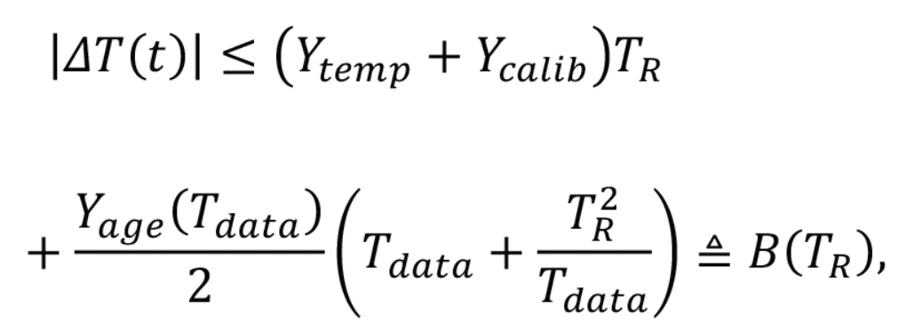
Bound on the Total Misalignment. In general, the cross-correlation between the uncertainties is unknown; we can only consider the worst-case scenario where the total uncertainty is bounded by the sum of the single bounds. This choice represents a prudential and conservative approach that may yield a rather loose bound with very high probability.
Thus, considering that all terms in the clock error bound increase over time, we can bound the total misalignment as
(2)
Example Values from Datasheet Specifications
Based on the above result, we can deem a commercial oscillator suitable for OSNMA operation if B(TR )≤TL. We can then compare the requirements for different RTCs, focusing on TCXOs designed for GNSS receivers suitable for the automotive scenario, with f0=52 MHz and a target operating temperature range between –20° Celsius and +85° Celsius. We assume that devices are subject to a calibration process, such that YcalibYtemp; thus we have neglected the calibration accuracy loss. We report in Table 2 the values of the misalignment bound, B(TR ), for TR=2 years and the maximum reset period TR,max such that B(TR,max)≤TL, with a loose time synchronization requirement TL=165s, as computed form the specs found in the datasheets.
Table 2. Bound values B(TR) and TR,max computed using several RTCs’ datasheet specs with TL=165 s and TR=2 years.
Conclusions
To ensure the authenticity of the GNSS navigation message, the Galileo OSNMA protocol requires a loose synchronization between the transmitter and the receiver. The misalignment between transmitter and receiver clock needs to be lower than a threshold TL for the whole holdover period TR. In this article, we have investigated the causes of the misalignment and frequency deviation in clock generators commonly found on the market and defined a general relationship between TL ,TR and the specifications commonly found in datasheets. Finally, we examined several mass-market temperature-controlled crystal oscillator datasheets, evaluating their performance in terms of worst-case offset bound B(TR).
The bound represents a prudential conservative approach and may be rather loose. However, given the lack of a consistent statistical model, this is a reasonable solution. We conclude that most devices can satisfy the constraint B(TR)≤TL=165 s with a workshop reset period of TR = 2 years.
Acknowledgements
This study was conceived within the PATROL (Position Authenticated Tachograph foR OSNMA Launch) project, funded by the EU Agency for the Space Programme through the Fundamental Elements programme, under procurement No. GSA/OP/23/16 “Development, supply and testing of a Galileo open service authentication user terminal (OSNMA) for the GSA.”
The authors acknowledge the invaluable support provided by the PATROL technical team: Davide Marcantonio (Qascom), Fabio Pisoni, Giovanni Gogliettino and Domenico di Grazia (ST Microelectronics), Alexandre Allien and Francois Riou (FDC), Jacques Kunegel (ACTIA), Simón Cancela Díaz and Belén Villanueva Coello (GMV).
PATROL success was fostered by the commitment and support of Flavio Sbardellati (EUSPA Project Officer), Gonzalo Seco Granados and Alexander Rügamer (EUSPA external reviewers), Javier Simon (EUSPA reviewer), Ignacio Fernandez-Hernandez and Giovanni Vecchione (EC reviewers). The authors thank colleagues Giada Giorgi (UNIPD) and Lorenzo Dal Corso (Qascom) for reviewing this work.
The content of this publication does not reflect the official opinion of the European Union or of the EU Agency for the Space Programme. Responsibility for the information and views expressed therein lies entirely with the authors.
Francesco Ardizzon is a Ph.D. student and Nicola Laurenti an associate professor in the Department of Information Engineering of the University of Padova, Italy. Carlo Sarto is the head of the security engineering division and Giovanni Gamba the head of the SIGINT and EW division at Qascom S.r.l., in Bassano del Grappa, Italy.
REFERENCES
A. Perrig, R. Canetti, J. Tygar, and D. Song, “The TESLA broadcast authentication protocol,” RSA CryptoBytes, vol. 5, 11 2002.
I. Fernandez-Hernandez, T. Walter, A. Neish, and C. O’Driscoll, “Independent time synchronization for resilient GNSS receivers,” in 2020 International Technical Meeting of The Institute of Navigation, 02 2020, pp. 964–978.
I. Fernandez-Hernandez, V. Rijmen, G. Seco-Granados, J. Simon, I. Rodriguez, and J. D. Calle, “A Navigation Message Authentication proposal for the Galileo Open Service,” NAVIGATION, vol. 63, no. 1, pp. 85–102, 2016. [Online]. Available: https://onlinelibrary.wiley.com/doi/abs/10.1002/navi.125
L. Cucchi, S. Damy, M. Paonni, M. Nicola, M. Troglia Gamba, B. Motella, and I. Fernandez-Hernandez, “Assessing galileo OSNMA under different user environments by means of a multi-purpose test bench, including a software-defined GNSS receiver,” in 4th International Technical Meeting of the Satellite Division of The Institute of Navigation (ION GNSS+ 2021), 9 2021.
“IEEE standard definitions of physical quantities for fundamental frequency and time metrology—random instabilities,” IEEE Std 1139-2008, pp. c1–35, 2009.
J. Vig, “Quartz crystal resonators and oscillators for frequency control and timing applications – a tutorial,” in IEEE International Frequency Control Symposium Tutorials, 2016.
M. Lombardi, “Fundamentals of time and frequency,” in The Mechatronics Handbook, CRC Press, 01 2002, ch. 17.
R. Filler and J. Vig, “Long-term aging of oscillators,” IEEE Transactions on Ultrasonics, Ferroelectrics, and Frequency Control, vol. 40, no. 4, pp. 387–394, 1993.
W. Riley and D. Howe, Handbook of Frequency and Stability Analysis. Special Publication (NIST SP), National Institute of Standards and Technology, Gaithersburg, MD, 2008-07-01 00:07:00 2008.
“Performance specification: oscillator, crystal controlled, general specification for,” MIL-PRF-55310F, 2018.
Approaches to providing real-time kinematic (RTK) solutions at high rates have existed in various forms for decades, providing value for high precision applications. This technique is nearly universally adopted in the industry, and many surveyors may have been using it for years without realizing it. Yet there are persistent misconceptions about the subject.
By Gavin Schrock, PLS
For many on the development side of high-precision real-time kinematic (RTK) GNSS, like those we interviewed for this article, the incorporation of high-rate solutions into their RTK products is a given — and has been for a very long time. Yet, in some end-user communities there may still be many question marks: Does my gear do it? Does other gear do it? What can it do for me? What are the pluses and minuses?
We asked for insights from 10 prominent firms that develop and manufacture RTK-enabled high-precision GNSS solutions and equipment, spanning multiple applications:
By high rate, we mean higher than 1 second (1 Hz) increments, such as 0.2 second (5 Hz), 0.1 second (10 Hz), etc. Part of the confusion about high-rate RTK is that there are two scenarios. One is transmitting corrections from a base or network at high rate, receiving and solving on-the-field sensors or rovers at a high rate (for example, 5 Hz base + 5 Hz rover).
The other is base transmission of corrections at a lower rate and receiving/solving on the rover at a higher rate (for example, 1 Hz on the base + 5 Hz or more on the sensor/rover).
While both can be valuable for different applications, what has been adopted as standard for most surveying, construction, agriculture and mapping applications is the latter.
What are applications that would run the base and rover at higher than 1 Hz? “Moving Base” applications are prime examples, where you are seeking to resolve positions for one or more sensors relative to a base that is also on a moving platform. Think of a barge on the ocean where a helicopter (or rocket) might be landing. Here is a definition from the user manual for a popular OEM receiver that has been in many makes and models since 2003:
“Moving Baseline RTK is an RTK positioning technique in which both reference and rover receivers can move. Moving Baseline RTK is useful for GPS applications that require vessel orientation. [For example, the] reference receiver broadcasts [correction] data at 10Hz, while the rover receiver performs a synchronized baseline solution at 10Hz. The resulting baseline solution has centimeter-level accuracy. To increase the accuracy of the absolute location of the two antennas, the Moving Reference receiver can use differential corrections from a static source, such as a shore-based RTK reference station.”
Beyond such specialized applications, running the base at a high rate is a burden on radios or bandwidth. Additionally, as industry experts explain below, it is of little (or no) value and may only unnecessarily use excess bandwidth and burden broadcast radios.
When would you run the base at 1 Hz and the rover at higher than 1Hz, such as 5Hz, 10Hz, or more? When the base is static. That pretty much covers nearly all surveying, mapping, precision agriculture and construction applications. What is meant by high rate in the sensor/rover receiver and its RTK engine, in the context of such applications? As one of the firms interviewed stated:
“The number of RTK position fixes generated per second defines the update rate.”
For most of the surveying, mapping, precision agriculture and construction applications, that means base 1 Hz + rover 5 Hz or 10 Hz. Then there are specialized applications, such as structural monitoring and geophysical studies, that may run sensors/rovers at 20 Hz, 50 Hz or (though rare) as high as 100 Hz. Whether a higher rate is a default, or 1 Hz is the default, changing the rate is almost always a user-configurable option.
A general perception is that base-rover gear defaults to base 1 Hz + rover 1 Hz. However, as the experts below note, that is not necessarily the case — often the rover rate is higher by default.
By any other name…
The respective approaches, and their appropriateness for different end-use applications, may seem fairly straight forward. However, part of the confusion about the subject for end users comes from the wide range of terminology used to describe how high rate is applied across the industry.
The understanding of processing approaches is clear among GNSS engineers, and in specific terminology, but this rarely gets translated well or consistently in terms meaningful to end users in documentation or marketing.
Developers might have different approaches to achieving high-rate solutions and would of course not wish to completely reveal their cards, but many of the fundamentals are the same. A mutual recognition of parallel development among GNSS engineers, and the manufacturers they develop for, in that each strives to continually improve solutions, means that the high-rate element of RTK generally does not get much marketing hype.
Often, when high-rate RTK does get laterally mentioned — in manuals, marketing or labeled as configuration options in GNSS field software — the mix of terms can confuse the user. Such terms as extrapolation, prediction, update rate and solution rate could evoke a negative connotation to an end user who is used to hearing one set of terms, and they might view otherwise like terms as contrasting terms.
GNSS engineers do not have issues with mixed terms. As some indicated in their respective interviews, they seem a bit puzzled as to why anyone would misunderstand the subject, and how marketing spin might lead users to be confused.
In recent years, the subject seemed to get discussed a lot more than usual in various high-precision end-user social media platforms. Perhaps this was a natural progression in growth of understanding of the nature of GNSS among these constituencies, and a desire to know more about what goes on in those black boxes — a positive thing. There may also have been some instances of marketing nudge.
For whatever reason it became a subject of discussion, we heard from readers who asked us to look into it. So here, in alphabetical order, are insights from of the experts in this field. You can jump ahead to the specific section for your equipment vendor, but we encourage you to read through each; combined, they provide a more complete picture of the subject.
Bad Elf
With Larry Fox, VP for Marketing and Business Development
Larry Fox uses the Bad Elf Flex. (Photo: Bad Elf)
Bad Elf has long provided GNSS solutions for aviation- and mapping-grade field applications. Several years ago, the company introduced a survey-grade-precision system, Flex. It is offered with an option for a modest initial investment in the hardware, and an innovative token system for enabling and operating at centimeter precision.
Larry Fox has been in the industry for a long time and has seen the evolution of real-time GNSS. He is Bad Elf’s vice president for marketing and business development, but he also had a key role in the development of the Flex system. Fox said that, of course, high-rate RTK is supported. “We allow options up to 20 Hz on the rover if the user has this enabled.”
For the approach of 1-Hz base and higher rates on the rover, he said that Bad Elf does not have a specific term for this. “For purposes of description, I could refer to it as high update rate, but I suspect high solution rate is pretty much synonymous.”
Fox explained how the standard approach works. “The rover knows the location of the fixed base and therefore applies the same processing techniques by simply reusing the last received data.”
He also mused about various hypothetical scenarios. “Given that the converse is also possible — a slow data rate from the base, say, 0.2 Hz at the base and 1 Hz at the rover — is there fundamentally any difference?”
For many applications, Fox does not see a substantial advantage in running at higher rates: “I see no benefit for higher data rates in a static situation such as a survey. I would argue that in a survey workflow, one should allow the RTK algorithm to settle over the static shot being taken, as the RTK algorithm likely benefits from aging out some of the data it used while moving.”
He adds, “I would suggest that once you have occupied a point for a modest amount of time and you remained fixed, I can’t see any benefit. My argument here is that by the time you have leveled and prepared your collector of choice, any decent RTK receiver with a good sky portrait and good corrections will not observe any benefit.”
As for disadvantages and trade-offs, “More and faster data,” Fox said, “must be better, correct? Sarcasm included. Unless there is a tangible need for more samples, what is one going to do with all the extra data? I could have seen a possible argument that a single constellation receiver may benefit from averaging, but that could be a be a whole different subject as multi-constellation is now standard. Arguably, at a higher data rate one could capture more epochs and reduce the time on station. With multi-constellation receivers I am just not convinced that these techniques have the same merit they may have had in the past.”
Bad Elf doesn’t support higher correction transmission rates from the radio. “The current module only supports RTCM3 at a 1Hz rate,” Fox said. “Even if we could transmit faster, the payload required would exceed the capability of the message transmission rate of the radio. The battery life of a radio is directly correlated to the transmission duty cycle. The more you are transmitting, the less battery life you will have. I would argue this would impact the useful field time you would have without an external battery solution.”
Fox notes that any application where a rover is moving — such as on a vehicle or for machine control — could benefit from high rate. “I could see a potential application for drones,” he added. “I would want to have the epoch of an image recording very tightly coupled to the image captured. Fundamentally, an RTK drone’s imagery is only as good as that. If one was taking video at any reasonable framerate, a higher frequency RTK GNSS may benefit the geolocation of more individual frames with less extrapolation.”
What about rates higher than 20 Hz? “We have run our receiver up to 20 Hz on the rover side. Although there are units capable of even higher rates, I don’t have any data that would convince me that this is viable, for mapping or surveying.”
I asked about some of the misunderstanding out there about high-rate RTK, and Fox replied, “We can be creatures of habit and tie ourselves to beliefs that ‘this is the way I did it and it worked then.’ People should always ask themselves the question, ‘do I still need to do it this way?’ Again, there is the premise that more is better. I can’t tell you how many times I have seen people collect very high-rate data for lines and poly features only to decimate the data because it reduced performance, increased storage, or lowered the performance of the apps rendering the data.”
Emlid
With Svetlana Nikolenko, Lead Application Engineer
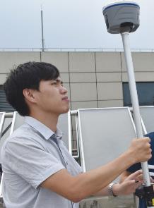
Photo:Svetlana Nikolenko with an Emlid GNSS receiver. (Photo: Emlid)
Emlid, a relatively new entrant to the market for high-precision GNSS, has made a splash with their line of affordable systems, such as the Reach RS2 rover and base-rover kits, and RTK systems for UAVs.
“All our devices support this,” said Svetlana Nikolenko, lead application engineer. “We do not have a special term for this, as it is simply a standard. We recommend 5 Hz and higher for a moving rover, but it can be overkill for a stationary one.”
Asked why one would want to run at high rate, Nikolenko explained, “The need to set a higher update rate depends on the rover’s velocity and acceleration. The higher the update rate, the more solutions per second are calculated. So, if you’re moving fast, the higher update rate simply allows you to keep your position current. If the rover is stationary, there are no issues with working at 1 Hz. Still, there is nothing wrong with running a stationary rover at 5 Hz or higher: it is excessive, but produces more samples with different satellite geometries.”
For moving applications such as UAVs, higher rates are of value. “It really depends on velocity,” Nikolenko said. “For example, if the rover is on a drone flying at a speed of 5-20 m/s and the update rate is set to 1 Hz, you won’t have the actual positions of the images. The higher update rate our devices have is 10 Hz, and at a drone speed of 20 m/s, even if you take photos each second (which might be a bit excessive), you’ll get accurate positions.”
Using an Emlid receiver in harsh conditions. (Photo: Emlid)
Emlid does not support a moving base. However, if there is a strong demand from users, they will consider adding this. For non-moving applications, Nikolenko said, an approach of broadcasting from the base at a high rate is excessive. “This increases the load on the radio (or any other connection link) because the base sends its position and corrections to the rover as often as it calculates it. Anything excessive simply adds load to processors and batteries.”
CHC Navigation
With Carlos Cao, Technical Manager for the Asia-Pacific region
CHC Navigation, or CHCNAV, has steadily grown as a recognizable brand of GNSS and other geospatial products internationally. While the brand might be new to some in North America, in some regions of the world CHC has a substantial share of the market, selling hundreds of thousands of units over the past 15 years. The company develops its own solutions, but also incorporates OEM components. In all cases, CHCNAV has provided high rate as standard from its earliest days.
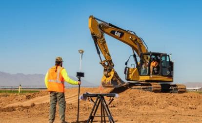
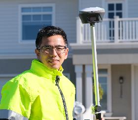
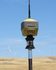
Multi-constellation rover with tilt compensation. (Photo: Schrock)
Carlos Cao, technical manager for the Asia-Pacific region, said that his company supports the approach of broadcasting at 1 Hz and solving at higher rates on the rover. “For example, you can get coordinates every 0.2 seconds in the Landstar 7 Topo Survey software,” said Cao. “Meanwhile, with different OEM boards, RTK models and supported software, [the equipment] can also reach 10-Hz or 20-Hz static data recording and NMEA data output (including GNGGA coordinate data).” Their term for solving RTK solutions at a high rate on the rover is “high update rate.”
This can bring advantages, specifically for moving applications, Cao said. “When you stake out, the 5-Hz update rate brings faster coordinate updates, especially when surveyors walk quickly. When you survey by time during movement, you can get denser points; while you survey by distance, the accuracy will be better if you are at high speed. For example, speed is 6 m/s, and you want to survey a point every 5 meters; 1 Hz update rate cannot do this with high accuracy.”
When would 1Hz be sufficient? “Normally,” Cao said, “a 1 Hz update rate is enough for a topography survey because users won’t survey at a high speed, so our default setting is 1 Hz, though you can choose higher rates if enabled and as needed. Unless you are moving, however, such as when some surveyors mount a rover on a vehicle, there is no significant difference in the final results.” He added that running at high rates can drain the battery faster.
Broadcasting at higher rates has several major issues. “With more satellites launched, especially BeiDou, correction data becomes much larger,” Cao said. “It means that network RTK requires more data flow, and UHF radio RTK needs a UHF modem that can send data at a high rate. It is a very big challenge for base RTK.”
Meanwhile, notes Cao, “The rover could even have a correction age of 5 or 10 seconds, and it will use the previous package to calculate the position. Since 1-Hz base and 5-Hz rover can work without degradation of precision, there’s no need to change the base to 5 Hz.”
Other applications CHC supports often use higher rates. “Navigation, machine control and precision agriculture normally use a 10-Hz, 20-Hz or 50-Hz update rate,” Cao said, “because these devices work under high-speed movement status, especially navigation. Also, they need to combine with high-update inertial measurement unit (IMU) data. The max update rate is 50 Hz. Normally the application data for these uses is NMEA data output by COM port or TCP/IP protocol. For surveying applications, such as topography, 1-Hz base and 5-Hz rover is enough. For other applications that need higher rates, we also provide such devices.”
Hemisphere GNSS
With Kirk Burnell, Senior Product Manager
Kirk Burnell
“At Hemisphere, we simply refer to this as RTK,” said Kirk Burnell, senior product manager for Hemisphere GNSS. Burnell added that they do not have any special term for this — it is simply a standard.
We were discussing specifically the approach of solving on the rover at higher rates than the base corrections. “All Hemisphere RTK products can work in this way, meaning corrections can come in at 1 Hz or slower, and rover output can be at 1 Hz, 5 Hz or 10 Hz as the user sees fit and as the application demands.”
Hemisphere develops GNSS and multi-sensor solutions for many industries: surveying, construction, agriculture and more. While Hemisphere has its own branded survey rovers, its OEM boards are in many other popular rover brands, makes and models. So, whichever you are running, you get high rate as a standard option.
Hemisphere’s receivers are frequently used in construction applications. (Photo: Hemisphere GNSS)
Burnell explained further that this is a given in the industry. “This is the standard expectation for RTK amongst our competitors, based on their product offerings, documentation, and standard operation. When describing RTK, the expectation is for 1-Hz base-station corrections, and a user-selectable rover output rate. Understandably, when people discuss RTK in technical terms, they may use different phrases to help distinguish between different techniques, which is why there might be different phrases out there. For us, it is simply RTK.”
As for the benefits of high rate, Burnell explained that inside the receiver, the measurement engine and RTK algorithms are typically running at 10 Hz or 20 Hz, and the selected output rate of the solution does not impact the RTK engine’s performance. The receiver will fix as fast and as accurately as possible given the quality of the RTK correction stream. Survey users could see a smoother update rate on their screen using 5 Hz compared to 1 Hz. This makes such tasks as leveling the rod or watching the change in height on screen while moving from the bottom to the top of a curb feel more natural. The user is not waiting an extra second each time to see the stability of the output. “A 5-Hz update rate is a good tradeoff for smooth workflows versus consuming CPU and battery power, compared to 10 Hz or 20 Hz,” he explained.
Would there be a disadvantage to simply running the rover at 1 Hz? “When using a 1-Hz update rate to the data collector, there will be fractions of a second spent waiting for the screen to update,” Burnell said. “Over the course of a day’s work, this could add up to a few minutes of extra time spent. In reality, this does not impact the ability to deliver a job on time. If the user does not feel impeded by the slower update rate of the screen, there is not a significant difference between the quality of the data, comparing 1 Hz and 5 Hz.”
Addressing one misconception that some users have about high rate, that it might significantly improve precisions, Burnell clarified, “For classic RTK surveying, outside of the workflow differences for the surveyor, the same quality of data is produced.”
Disadvantages? “Once you move beyond 5 Hz you start to exceed people’s hand-eye coordination ability, and the benefits diminish,” said Burnell. “Additionally, the data collector has a lot of communication to process, data to unpack, calculations to do, and screen refreshes to accomplish. Faster than 5 Hz leads to stresses in these aspects of the user experience, and ultimately can consume the data collector’s batteries at a faster rate.”
There have been instances of high rate being marketed as enabling users to save a lot of time, but as Burnell noted, this might actually be a potential problem. “There could be a false sense of having no latency, which could lead to rushing through a job, increasing the chances of making a mistake. A surveyor’s observations and measurements are the currency of their trade, and they should be made with care and attention to the work being done. Most surveyors take pride in a job well done.”
Regarding the other scenario, broadcasting at a high-rate and solving on the rover at the same high rate, “This mode of RTK operation has little or no benefit and a host of drawbacks,” Burnell said. “The biggest issue is the volume of data. For a multi-frequency multi-GNSS solution, there is an immense amount of data to be transmitted from the base to the rover. Running a link at 5 Hz requires huge data bandwidth generally only possible using an internet link as compared to a 450-MHz or 900-MHz radio link. Drawbacks for internet links are data volume costs. For dedicated radio links, the issue is most likely to impact radio range. To send five times as much data, the over-the-air baud rate needs to be five times greater. This means that the energy per bit of data is five times less when at high speed. The signal will lack the ability to punch through obstacles. While some may suggest that having five times as many corrections reach the rover compensates for this, some radio protocols can be configured to transmit multiple retries with 1-Hz data.”
However, there are advantages to running at higher rates for specific applications, Burnell said. “If data is being collected in a kinematic fashion as compared to shooting individual points, there will be more detail when collecting at 5 Hz. For example, driving along a road with a receiver mounted to the roof, in 1 minute of driving there will either be 60 measurements at 1 Hz or 300 measurements at 5 Hz. For many non-survey applications, this is critical. For example, at highway speed, 1-Hz data means 1 point every 30 meters (100 feet) or so. In machine control, the systems are not relying on hand-eye coordination and reaction time, and 20 Hz or 50 Hz are common speeds. Autonomous applications also typically use between 10 Hz and 50Hz for GNSS, and often combine this with 100-Hz or 200-Hz IMU data. Aerospace and defense applications have demanding conditions and use 100-Hz to 200-Hz IMU data to navigate, often combined with 1-Hz, 10-Hz or 20-Hz GNSS data.
There are even some applications for which it is warranted to broadcast corrections at rates slower than 1 Hz. “One example was a user in Japan, where radio links are often throttled to 4800 baud,” said Burnell. “They were looking to see how to slow down corrections to less than 1 Hz so that they could take advantage of multifrequency multi-GNSS RTK. Another example: I recently asked for some 10-Hz rover data for analysis. With very large files, analysis took much longer — I wished I had asked for 1-Hz data!”
Hexagon | NovAtel
Hexagon | NovAtel is a prominent tech firm providing positioning, navigation and timing (PNT) solutions for multiple industry segments, including defense, surveying, construction, agriculture, autonomy and more. While GNSS is a core technology, NovAtel develops multi-sensor systems (including inertial) and has a broad reach with its OEM products. Surveyors, for instance, might not be familiar with NovAtel first-hand, but have likely used its technology via NovAtel’s many OEM customers.
Iain Webster
Iain Webster, senior director of Geomatics and Software Engineering for NovAtel, said that not only does NovAtel support high-rate RTK, but the customer can choose the position output rate desired — 1 Hz, 5 hz, 10 Hz, 20 Hz, etc. — and the receiver will output RTK positions at that rate.
“We distinguish between a matched solution (where a correction is matched with a rover observation at the same time tag), and a low-latency solution, where base observations are extrapolated for position computation at the rover,” Webster said. He provided a description from a company manual:
“The RTK system in the receiver provides two kinds of position solutions. The Matched RTK position is computed with buffered observations, so there is no error due to the extrapolation of base station measurements. This provides the highest accuracy solution possible at the expense of some latency, which is affected primarily by the speed of the differential data link. The MATCHEDPOS log contains the matched RTK solution and can be generated for each processed set of base station observations.
The Low-Latency RTK position is computed from the latest local observations and extrapolated base station observations. This supplies a valid RTK position with the lowest latency possible at the expense of some accuracy. The degradation in accuracy is reflected in the standard deviation. The amount of time that the base station observations are extrapolated is in the “differential age” field of the position log. The Low-Latency RTK system extrapolates for 60 seconds. The RTKPOS log contains the Low-Latency RTK position when valid, and an “invalid” status when a Low-Latency RTK solution could not be computed. The BESTPOS log contains either the low-latency RTK, PPP or pseudo range-based position, whichever has the smallest standard deviation.”
NovAtel does not brand this as a specific feature — it is just a standard part of its RTK solutions, but the company refers to it in their documentation as a “low-latency” solution.
The main benefit of this solution, Webster explained, is for kinematic users to allow better representation of their actual trajectory (such as in applications on moving vehicles). “The higher the dynamics, the more impact the latency of the matched solution will have to the point that we recommend the low-latency solution to all but specialist customers with known static positioning needs. For surveyors, there may be improved workflow with the low-latency solution as they will be able to move from point to point more quickly.”
NovAtel produces GNSS and inertial hardware and software, including OEM boards, for multiple applications. (Photo: NovAtel)
Webster noted that for applications where the rover is static for observations, 1 Hz can be fine, but for moving rover applications — kinematic — running at 1 Hz is probably unacceptable, so low latency is quite standard.
Additionally, he pointed out, there are applications where longer periods between corrections may not necessarily be detrimental. “Note that some manufacturers, including NovAtel and Leica, offer the possibility of using PPP corrections to extend RTK solutions beyond, for example, a 60-second timeout,” Webster said. “There are various proprietary methods to achieve this, but ultimately the RTK solution could be extended without limit in this way.”
Are there tradeoffs to using extrapolation or other high-rate approaches? “With corrections coming in at 1 Hz,” Webster said, “there is very little error over that period, so for most users, there is little disadvantage and perhaps some productivity advantage with a higher rate. If there is any trade-off, it is between getting the highest accuracy possible versus the lowest latency solution.”
As for the other scenario — the base broadcasting at greater than 1 Hz and the rover solving at greater than 1 Hz — “There is little advantage,” Webster said, “except in some specialized applications such as when the base is moving (called moving baseline) to provide a cm-level baseline between the base and the rover for relative positioning. For typical surveying applications with a static base, the rover would have to wait until the corrections arrived before outputting a solution. Other downsides include increased bandwidth on the communication link and more loading on the rover CPU, meaning lower battery life.”
What are the non-surveying applications where a high rate (in either scenario) can yield a specific benefit? Webster noted that, in fact, they deal mostly with non-surveying applications. “Most use cases need 10 Hz or 20 Hz for machine control or precision ag. We do have some very specialist applications that have required up to or beyond 100 Hz — but it is often best in those cases to do a GNSS/inertial navigation system (INS) solution and use the IMU to output at that a high rate. As previously mentioned, there are other specialist applications where the base is moving. In this case, we run a matched solution at a high rate between the base and the rover.”
Leica GeoSystems
With Xiaoguang Luo, Senior Product Engineer, GNSS Product Management Group
Rover with calibration-free tilt compensation and camera-based offset point capabilities. (Photo: Schrock)
Leica Geosystems (part of Hexagon) has been a major global developer and manufacturer of GNSS systems for multiple disciplines for several decades, introducing its first GPS receiver, WM101, in 1985. Since then, Leica has been among the leaders in GNSS receiver innovation, including integrated systems such as a rover that incorporates calibration-free tilt compensation and an image-point capture feature (GS18 I). Therefore, it is no surprise that for Leica Geosystems equipment features high-rate RTK as standard.
Xiaoguang Luo is a senior product engineer in the GNSS Product Management group at Leica Geosystems. He confirms that this option is supported in all Leica Geosystems RTK rovers of the current product portfolio, and this option is enabled by default in the Leica Captivate (surveying field) software. A term Leica Geosystems uses is prediction for its high-rate RTK approach.
Xiaoguang Luo
The standard positioning rate is 5 Hz on the rover. “As far as GNSS processing is concerned, there is no fundamental need to go to higher positioning rates,” Luo said. “The need for high rates is mainly driven by applications. For example, we are using the 5-Hz position update rate at the rover by default for an improved staking workflow and user experience. The 10-Hz rate is also supported in Captivate, for example, when streaming NMEA messages.” He added that 10 Hz is supported for other applications, such as structural monitoring, and 20 Hz for machine control.
As for the advantages of a rate higher than 1 Hz, Luo said that working at high observation and solution rates enables the possibility of modeling fast-changing error effects with a period below 1 second, and allows for high-rate non-surveying applications such as bridge monitoring. Does a high rate have any significant effect on the final results? He said that it strongly depends on the use case where high-rate observations and positions are involved. In addition, the quality of prediction also affects the final results.
Bernhard Richter
By this he means that while the standard approach for applications where the base is stationary, such as surveying, can work so well with a base data rate at 1 Hz and rover at 5 Hz, the key conditions do not change much over a single second.
Luo’s colleague Bernhard Richter, vice president of geomatics, explained it. “To understand this, you need to separate the elements of corrections into those that are fast changing and range dependent (see the graphic below). If the errors change slowly, then they can be estimated and predicted very well. Or, if the range dependency is low, errors could come from a different source than the base station. If the range dependency is medium or high, then the corrections are more difficult to estimate on the rover side, but if such errors change very slowly, they can still be predicted very well with the precondition that corrections have been received at least once.”
The rate of change and dependencies for the elements of corrections. (Source: Leica GeoSystems)
You’ll notice that multipath is high in both regards. This brings up another misconception about high-rate RTK — some users have an expectation that it will improve their performance in limited sky-view situations (like thick tree canopy) or high multipath environments. This is not so. Any improvements in such environments come from having more satellites, more observations, and more modernized signals. With regard to high-rate and multipath, Richter said, “It is anyway futile, since multipath decorrelates so quickly that the advanced mitigation has to happen both in an analog and a digital way on the rover.”
While there are benefits to running at high rate, such as for staking, a balance has to be struck — for instance, in not running it at too high a rate. Luo outlined disadvantages that must be considered when performing high-rate RTK.
High processing load and battery drain, particularly with multi-constellation and multi-frequency RTK.
High temporal correlations between observations, which may not be considered in a sophisticated manner in the RTK algorithms.
High base rates provide challenges for the RTK data link devices, such as radios.
In addition, he noted that while any kind of predictive solution will introduce some amount of error, that would be so small in, for instance, a base data rate at 1 Hz and rover at 5 Hz solution, as to not even be noticeable in the positioning results.
Septentrio
With Bruno Bougard, Research and Development Director
Bruno Bougard
“Our rover solution computes RTK up to 100 Hz,” said Bruno Bougard, R&D director at Septentrio. “Update rate requirements for industrial machine control applications are typically 20 Hz. This is necessary to capture the motion dynamics. Also, it is not only the update rate that matters in those applications, but also the latency, which should be low (<20 ms typically) and constant.”
Septentrio NV is a designer and manufacturer of high-end multi-frequency GNSS receivers and integrated solutions. Markets they serve include surveying, mapping, construction, science, timing, agriculture, marine, autonomy, and more — all with specific applications where high-rate RTK may be employed They also provide OEM boards and modules for further integration by others.
Surveying users for instance may be familiar with their Altus line of rovers, such as the NR3, where high rate is a standard option. “There are new applications where a higher update rate is required,” said Bougard. “Surveying with UAV, using photogrammetry or lidar scanning requires at least 10Hz. In mobile mapping in general, RTK-INS solutions such as SPAN, Applanix or Septentrio SBi, require update rates up to 200Hz.”
Bougard acknowledged that manufacturers use many terms for their high-rate solutions. “Some may be used to masquerading a low-rate solution as a high-rate one. This is not what we do. The rover observables are captured at high rate and can be up to 100 Hz. The rover RTK filter is also run on high rate. Fixed base-station data does not have to be high rate. 1 Hz is typically enough. For moving base applications — for example, when the base station is on another vehicle, and we want to compute the baseline between the moving base and the rover — 10 Hz is required.”
Bougard said that the benefit is to track the motion of the rover. This is critical in machine control, but also relevant for new survey flows (such as UAV-based and mobile mapping). The disadvantage, he explained, is that it requires higher CPU loads. “Suppliers, who focus on cost, tend to compromise on this, notably running higher rate only for a subset of the constellation or signals. We use them all.”
Is running the base station at a higher rate advantageous? “It is possible to increase the output rate of our base station correction stream but, as explained, this is not needed if the base is static,” Bougard said. “This is applicable to moving base scenarios as explained above. Indeed, if you increase the base-station correction rate, the bottleneck becomes the datalink.”
Tersus GNSS
With Xiaohua Wen, Founder and CEO, Tersus GNSS
Xiaohua Wen with a Tersus GNSS receiver.
Xiaohua Wen, based in Melbourne Australia, is the founder and CEO of Tersus GNSS, another new entrant in the centimeter-grade GNSS market. One distinction about Tersus is that the company has developed and produces its own GNSS boards, instead of using OEM boards from other companies. Tersus implements its own tech, including GNSS receivers and IMUs in its own survey rovers, such as the Oscar, and for other high-precision applications. Additionally, it produces OEM boards for integration by others. Tersus entered the market with full multi-constellation support and, of course, high-rate RTK options, and has recently announced a PPP (precise point positioning) service.
“Our RTK boards support up to 20 Hz,” said Wen. “Often, surveyor will choose 5 Hz. We do a 5-Hz solution in this manner: the baseband takes raw measurements at a wanted moment, say at 1.2 s or 1.4 s, and RTK calculates solutions with the raw measurements. We understand that some older solutions might simply extrapolate or interpolate based on a position and velocity sequence, which is sometimes called predicted RTK or extrapolated RTK (though those terms get used in different ways by different developers). That is not how we approach our RTK solution updates. All Tersus RTK boards also support a maximum 20 Hz raw measurements outputs.”
Multi-constellation rover with calibration-free tilt compensation. (Photo: Schrock)
We asked about some of the advantages users may envision of high-rate RTK in general. Wen said there may be little or no gain with regard to faster initializations. Likewise, there is no significant gain with precision and accuracy. However, Wen said that higher rates can sometimes improve staking workflows. “For example, in the case of our Oscar rover with tilt compensation, the RTK outputs solutions at 10 Hz, while the IMU samples at 100 Hz. Oscar calculates the pole tip’s position at 10 Hz, aligned with the RTK solutions, and the data controller or tablet displays the point of the pole tip on the screen. We find that the point better refreshes at 2 Hz or higher to respond to the pole tip movements without noticeable lagging.”
That movement is an example of a key value of high rate,“Speed or movement,” Wen said. “For surveying applications, I would say that 1 Hz could suffice, considering the characteristic very low speed. Usually, applications like machine control and precision agriculture require an RTK update rate at 5 Hz or higher. Some UAV applications may use a 100-Hz position update. Most of these applications use an INS+RTK solution. With INS, it’s easy to get a 100-Hz position update, while for an RTK solution, a rate of 20 Hz is probably enough.”
Wen said that broadcasting corrections at a higher rate is pointless for most applications, “because the base data is highly correlated in the short term. If it’s a moving base, the high-rate base data would make some sense. Otherwise, it just imposes a greater load on communications and computation, with almost no gain.”
Topcon Positioning Systems
With Alok Srivastava, Director of Product Management
Alok Srivastava
“It is a standard option in our rovers,” said Alok Srivastava, senior director of Product Management (PM) at Topcon. “Around the time I joined the PM team, in 2010, the decision was made to make 10 Hz the standard, though this is user configurable and can be 5 Hz, 20 Hz, up to 100 Hz.” He explained that faster rates have been available through several generations of their receivers.
Typical applications consist of a static base and a moving rover. Fast-moving applications can benefit from higher rover position update rates since the RTK engine is computing real positions at a faster rate. Higher rates on the rover side provide accurate changes in position that can be missed by interpolating between positions computed at a slower rate.
A Topcon multi-constellation rover with tilt compensation. (Photo: Schrock)
High update rates on a base station do not provide advantages except in rare cases where the base is moving. While rovers are computing movements of the rover antenna, base stations are providing GNSS satellite corrections. A rate of more than 1 Hz for a static base station does not benefit rover accuracy; it only creates a burden on the communication between base and rover. Base and rover communication needs to be optimized to reduce bandwidth requirements. This is especially true as we continue to add constellations and signals to GNSS solutions.
Sufficiently high rates have been standard on Topcon rovers for a long time. Srivastava would rather see more focus put on other aspects of GNSS — such as interference, spoofing, the impacts of 5G, precise point positioning (which Topcon provides through its Topnet Live service) and sensor integration. “In many of our construction applications, we have IMUs,” Srivastava said. “When an application has an IMU for tilt compensation or for machine control, the IMU and GNSS complement each other. In kinematic mode, the IMU can help reject outliers.”
“High rate can be considered a common default mode of operation,” said Stuart Riley, vice president, Technology – GNSS, Trimble. “Typical rover position solution rates are 5 Hz, 10 Hz and 20 Hz.”
Trimble is one of the pioneering companies in GPS and GNSS, and Riley has been directly involved in the evolution of the company’s GNSS solutions for more than two decades. He has seen a lot of change, and in noting the nature of key technological advances, offered this intriguing observation about high rate: in many ways it has become less relevant.
“There have been considerable advances in RTK technology in recent years that make many of the earlier concepts related to how base and rover data should be combined for baseline processing largely irrelevant,” said Riley. “Most recently, survey receivers have included INS support for tilt compensation applications, and these receivers have available high-rate IMU data — at a much higher rate than GNSS observables — which drive the final GNSS/INS integrated solution. Thus, the rover GNSS data rate is not so important.”
Riley noted another relevant technology that Trimble has implemented: the use of precise satellite clock and orbit corrections — such as from the Trimble RTX precise point positioning (PPP) service — to augment RTK when there is a loss of the base correction stream. The implementation of PPP is broadening across the industry, and the company was an early implementer of a global service. It has the RTX-based xFIll feature that runs on and high-end survey receivers. One of the misconceptions about PPP services such as xFill is that it is just there to “take over” should the RTK or NRTK corrections be interrupted. Yes, it does that as well, but to be able to do that, it is running all the time, simultaneously with the RTK, so the rover is getting these enhanced PPP service clock, orbit and other data. This improves what the rover can do. “The emphasis in modern survey receivers,” Riley said, “is based more on the availability of rover data, and a fundamental base data rate of, say, 1 Hz, is all that is required.”
Along with various advances in the rover RTK engine, the GNSS constellations have expanded considerably, requiring increased bandwidth for the corrections from base to rover. “Our products can use various communication technologies to transmit corrections, such as Wi-Fi, cellular, and UHF (450 MHz or 900 MHz) radios,” Riley said. “Maintaining a 1-Hz correction rate enables all the GNSS observables to be broadcast from the base, providing a suitable highly compressed data format such as when Trimble’s proprietary CMRx format is selected.”
Many terms are used in the industry, and they typically refer to some proprietary aspect of an RTK engine. Riley said that a generic term would simply be high update rate. “Providing the position is based on the most current phase observables at the rover, a low latency solution is possible,” he said. “Thus low-latency solution goes hand-in-hand with a high update rate. Predicted RTK may refer to an old method where the static base corrections are propagated forwarded to account for radio latency and thus synchronize base/rover data. This is not used in modern PVT (position, velocity, time) RTK engines.”
High rate on the rover is standard, but what benefits should the user expect from it? “A fast update rate provides the best user interface experience in the field, in particular for stakeout,” Riley said. “Quite simply, nobody wants to be working with a laggy display. For survey field work, 5 Hz is typical. Other applications, such as machine control, benefit from higher update rates where a default of 10 Hz would be used, with options for higher rates.”
If the user chooses 1 Hz on the rover, what would be the downside? “Running at a 1-Hz rate is not really suitable for stake out,” Riley said. “For occupying static points, 1-Hz updates would suffice, as a typical occupation has a minimum time of 1 or 2 seconds. Very high rates for survey applications do not really buy anything in terms of field look and feel or performance.” I asked him about any points of diminishing returns, and he responded, “The higher the rate, the wider the measurement bandwidth (that is, the noise increases — you cannot get something for nothing), so in fact going for an unnecessarily high rate would start to be a disadvantage. For example, there would be no advantage to using a 50-Hz or 100-Hz rate for a land survey application. There is a relationship between measurement bandwidth and position noise.”
When is a high base rate a good idea? High rates are supported for some machine control and “moving base” applications where the reference frame has to move with the moving base, Riley said. In this case, the base and rover observables must be synchronized and the final solution has a fundamental latency depending on the base rate. For this reason, moving base rates are more typically 10 Hz or 20 Hz. For a static base, it is possible to use a higher rate. However, as Riley noted, “It’s more likely that a lower rate such as 0.5 Hz might be desirable to accommodate the radio when using repeaters (time multiplexing the data) or low data rates. There are disadvantages to high base rates, mostly related to radio bandwidth. Other factors, such as ‘high rate = more radio transmit power’, may need to be considered (affecting battery life).”
Are there other cases for even higher rover rates? “As mentioned, machine control applications use higher rates — necessary to reduce position latency in control loops,” Riley said. “Other applications such as UAVs and autonomous driving clearly benefit simply because of the speed of the platforms (higher dynamics). Precision agriculture is an excellent example of machine control, where auto guidance is used. Although high rates are possible, nearly all applications manage perfectly fine at rates up to 20 Hz. A more important consideration is system performance in terms of positioning accuracy and convergence times, which is dependent on the technology used in the PVT engine, such as Trimble ProPoint technology, rather than the correction stream data rate. ProPoint also includes xFill, as mentioned earlier, which provides centimeter-level backup for continuous operation when RTK or VRS correction streams are interrupted.”
Other Manufacturers
This was only a sampling of the developers and manufacturers, but it should be noted that several of the above firms produce OEM boards featured in dozens of other brands and models, such as Carlson and GeoMax. To try to list them all would be a challenge and might be missing a key point: high rate is quite standard, is not big news anymore, and you probably have it by default (or optional) no matter what system you are using.
Hypeful
As the insights the from industry experts above show: high rate can be essential for many applications, but unnecessary for others. It seems more about user experience (staking workflows or moving rover) than some way to seek higher precision.
Additionally, to borrow the gaming term hypeful, some users believe (or have been led to believe) that running at high rate will yield higher precision or work some kind of magic in dense tree cover or high multipath environments. Some may argue that it could get a result faster, but in practical terms even that might not be the case.
High rate has been around for a long time. And like any tech, has gone through different development and adoption phases. Think about automatic transmissions for motor vehicles; they have been around in one form or another for more than a century. There was a period in the mid-20th century where the development of different approaches was promoted in marketing campaigns with fanciful product names, like Durashift, Presto-Matic, Geartronic and Torque-Flite. But rarely do you see auto transmissions highlighted with such marketing flourish since then.
High-rate RTK was never singled out like that; it is common, and any differences are mostly in how it has been adapted for different applications. I suppose a firm could choose to emphasize it for marketing purposes and give it a buzz name like “Turbo Thrusted RTK”, which his fine for marketing purposes (albeit a bit “cheugy”). Every developer and manufacturer will have slightly different approaches, but if you believe, or are led to believe, that any represent high-rate fundamentals exclusively, that would be inadvertently misleading, if not subtle gaslighting.
As one of the experts said, “It does not really matter what manufacturers claim or don’t claim. You cannot beat physics. You can only understand and manage the physics.”
Coolness Ahead
While high-rate might seem a bit old hat, where GNSS development is going is not. The developers we interviewed are more interested in highlighting their complete high-precision solutions. For example, adding inertial measurement units (IMUs) for no-calibration tilt compensation, additional sensors for imaging (and likely soon, lidar), and multiple real-time GNSS solutions complimenting RTK, such as L-band precise point positioning (PPP).
The “high-rate” that is truly exciting is that of R&D, multi-sensor integration, automation of certain elements of workflows, artificial intelligence and multi-constellation/multi-signals.
Knowing your position is only part of navigation. (Photo: Oliver Montenbruck)
By Oliver Montenbruck and Peter Steigenberger
A year ago, the U.S. Global Positioning System celebrated its silver jubilee upon completing 25 years in operation. Also, it was more than 20 years ago that President Clinton agreed to switch off Selective Availability, thus offering seamless positioning to the civil community. The 10-bit GPS week count experienced its second rollover, and people worldwide got addicted to a ubiquitous positioning capability in those decades. Be it for finding the nearest restaurant or to track a Sunday afternoon bike ride, positioning-related services building on GPS have become an integral part of our daily life. In fact, GPS has almost become a synonym for navigation itself.
One cannot underestimate the contribution that GPS has made to society. It is for sure most deserved that the fathers of GPS were ultimately awarded the highly prestigious Queen Elizabeth Prize for Engineering in the year of the above jubilee. As always, success creates followers, and GPS is no longer the sole player. Next to the Russian GLONASS, two new actors — namely the European Galileo and the Chinese BeiDou-3 GNSS — have mounted the stage. So, users are now offered a choice of four independent GNSS.
However, do we really need so many systems? Isn’t one enough and all others just a waste of taxpayers’ money? The answer to the last question is certainly a clear “no.” Our society already depends on, to a large extent, the availability of positioning, navigation and timing (PNT) services in much the same way we depend on electricity and telecommunication. While mass-market applications such as the ones mentioned above may appear dispensable, there are “hidden” but much more critical applications of GPS, such as synchronizing power lines, stock trading or the base stations of cellular networks.
Clearly, there is a well-justified rationale for nations or groups of nations to build their independent, space-based navigation systems. Well beyond possible military considerations, this is a basic strategic interest for protection of the local economy and of critical infrastructure. Along with these interests, various regulatory conditions may apply that only endorse the use of selected systems for specific applications, such as emergency call systems. Overall, however, all GNSS in place today can be received and utilized by all interested users around the globe.
So, let’s have a closer look at the practical relevance and implications of having four GNSS in parallel for both mass-market and high-end users. The most obvious consequence is certainly an almost four-fold increase in the number of satellites. As of today, the four GNSS comprise more than 100 satellites, out of which 30 to 40 are simultaneously visible and available for positioning at common sites with open-sky conditions. As a rule of thumb, this provides a factor-of-two reduction of statistical errors compared to using only GPS.
Most importantly, however, the prospects for tracking enough satellites for positioning in obstructed sites is greatly improved. The larger number of visible satellites is particularly appealing for GNSS radio scientists who aim to derive temperature and humidity profiles from subtle variations in GNSS signals passing through diverse atmospheric regions. Multiple GNSS allow for better resolution and ultimately benefit weather forecasts.
In terms of positioning, the simple statistical benefits of tracking a large number of satellites are probably outweighed by technological advances in GNSS satellites and ground systems, as well as substantial progress in receiver technology. For GPS, the signal-in-space range error (SISRE) that describes the contribution of broadcast orbit and clock errors to the position accuracy has decreased by more than a factor of three (Figure 1).
FIGURE 1. Evolution of the GPS signal-in-space range error over time. (Image: O. Montenbruck and P. Steigenberger)
For GPS, but also Galileo and BeiDou-3, the use of highly stable atomic frequency standards has contributed to a notable reduction of the error budget of broadcast ephemerides. The same applies for fast upload capabilities, as in Galileo, or the use of intersatellite links in BeiDou-3. With SISRE values of 0.1–0.2 m and 0.3–0.4 m, these constellations enable even more accurate positioning today than GPS and GLONASS (Figure 2).
Figure 2. Signal-in-space ranging errors of the four GNSS. (Image: O. Montenbruck and P. Steigenberger)
However, improvements from new signals and multiple constellations are not only limited to single-point positioning, but likewise apply for precise point positioning (PPP) users. Stable clocks onboard the satellites reduce the update rate and bandwidth for real-time correction users. Digital signal generation units in modernized satellites ensure clean chip shapes in the transmitted ranging signals and reduce the scatter of satellite/receiver biases. Last but not least, the increased number of tracked satellites contributes notably to reducing the convergence time required for successful ambiguity fixing.
Concurrent progress in receiver technology was certainly a prerequisite for being able to track the multitude of new signals that became available with the new and modernized constellations. Compared to early GPS receivers with a few tens of channels, modern geodetic receivers may (or even must) support in the order of 1,000 channels. For mass-market users, the recent introduction of dual-frequency chipsets for mobile phones and car navigation systems marks the most important step forward. These chipsets support joint tracking of signals from GPS, Galileo and BeiDou-3 at the common L1/E1/B1 and L5/E5a/B2a center frequencies. The signals’ chipping rates, modulations and signal power are designed to offer reduced measurement noise, better multipath protection, and improved weak-signal tracking. At the same time, the use of two signal frequencies allows for rigorous elimination of ionospheric path delays, thus removing the biggest contributor to the error budget of low-cost positioning devices.
All in all, the availability of four GNSS means better performance, robustness, diversity and flexibility for navigation users. We should not forget, however, that all GNSS use basically the same core technology and share the same vulnerabilities. We must still give due attention to the challenge of toughening, augmenting and complementing GNSS to meet society’s needs for robust and assured PNT.
Oliver Montenbruck is the head of the GNSS Technology and Navigation Group and Peter Steigenberger is a senior scientist at the German Space Operations Center, German Aerospace Center (DLR).
Single-base RTK is an excellent choice for many uses but mixing different baseline lengths can yield inconsistent results
By Gavin Schrock, PLS
Gavin Schrock, PLS
The surveying lead for a construction firm started getting calls from his crews — suddenly they were not checking in to existing control with the accuracy required. This presented a conundrum and an immediate resolution was needed to stay on schedule. What had changed? A nearby permanent base, part of the regional real-time GNSS network (RTN), had suddenly gone dark, and when the crews switched to other bases, they got the inconsistent results. Time to call the RTN. (See a primer on RTN.)
I have been operating a regional cooperative RTN for 19 years, and I get these kinds of support calls regularly, but typically only from users of the single-base mountpoints. Most RTN provide, via NTRIP casters, both network RTK (NRTK) solutions — such as master-auxiliary, VRS and FKP — and single-base solutions for each base. The base they had been using was down while the roof of the city building on which it is mounted was undergoing some maintenance.
The construction firm, halfway through a multi-year transportation project, had used the base when they established project control, and for layout and as-built tasks. Using the base, which was slightly more than 4 km from the site, the crews were used to seeing check-in results of 0.3′ (9 mm) or better (horizontal). When they switched to different bases, 23 km and 25 km distant, the results were now inconsistent, and in many instances, double.
This was an easy fix. We met on site and checked results using the network solution; it closely matched the results they were seeing from the original base. Until the original base was restored, this would meet their needs.
It made a lot of sense to use the nearby base, as setting a temporary project base on the congested and sky-view challenged site was impractical. Furthermore, the baseline length of 4 km yields excellent results. Single-base RTK is a powerful tool, and a default for many construction projects, provided that:
the base has an unobstructed view of the sky
the base is free of nearby multi-path hazards
the base receiver and the antenna are of the same or better quality as the rovers
the base receiver and the antenna support the constellations and the signals desired.
In many ways, it is hard to beat single-base RTK. For instance, if you set up a base right on the site, say less than a kilometer away, this should yield the best results possible for RTK, and can be better than network RTK.
However, there are challenges. Single-base, typically “iono-free” solutions common in today’s rovers, degrades over the baseline length. The rule of thumb for many is that the degradation becomes noticeable when baseline lengths exceed 10 km. It is not uncommon for rovers to fix at much longer baseline lengths; 20 km, 30 km, 50 km or more — but results will likely vary from hour to hour or day to day. Changes in ionospheric and tropospheric conditions can bring inconsistencies, particularly over longer baseline lengths.
Network RTK may not beat single-base over very short baselines, but as it uses 5 to 15 bases (depending on the implementation) it can better model in the varied conditions. It can provide great consistency and repeatability, even if an individual base is unavailable, as was the case for this conduction site. There are strengths and weaknesses for both. NRTK brings consistency over a wide area, you do not have to set up (and guard) your own base, and the geodetic values are solved.
If you can have an on-site base, you can under certain conditions see a gain in results. This is especially important for certain applications, such as machine control and precision agriculture, for which tight year-to-year and row-to-row repeatability is key. However, if you may need to use another base at some point, you may be better off starting with NRTK, if it yields the results you seek.
Gavin Schrock is a practicing surveyor, technology writer, editor of xyHt Magazine and operator of a cooperative GNSS network.
In June 2019, Regulus Cyber’s experts successfully spoofed the GPS-based navigation system of a Tesla Model 3 vehicle. This experiment provided an important warning for all companies using GNSS location and timing: these technologies, on which they depend, are highly vulnerable to spoofing attacks. In the two years since the experiment, companies and governments have continued to research the potential harm that can be caused by spoofing attacks and are learning more about how to defend themselves from them.
The Tesla experiment was groundbreaking because it was the first time that a level 2.5 autonomous vehicle was exposed to a sophisticated GPS spoofing attack and its behavior recorded.
We chose Tesla’s Model 3 because it had the most sophisticated advanced driver assistance system (ADAS) at the time, called Navigate on Autopilot (abbreviated NOA or Autopilot), which uses GPS to make several driving decisions. However, this experiment exposed several cybersecurity issues potentially affecting all vehicles relying on GPS as part of their sensor fusion for autonomous decision making.
NOA makes lane changes and takes interchange exits once a destination is determined, without requiring any confirmation by the driver. Its several other features include autonomous deceleration and acceleration according to the speed limit, autonomous lane changing, and adaptive cruise control.
These features use a variety of sensors, including cameras, radar, speedometers and more. The researchers wanted to test the extent to which the Model 3 relied on its GNSS receiver to make these driving decisions and how it behaved when receiving contradicting information from its GNSS receiver and its other sensors.
The researchers used hardware and software purchased online to mimic the tools potential hackers would use. The experiment involved two software-defined radio (SDR) devices purchased online, one to spoof GPS and one to jam all other constellations, connected to an external antenna to simulate an external attack. The software used to simulate the GPS signal was downloaded from an online source, available for free.
The test included three scenarios the researchers assumed would involve usage of GNSS, each one using a different spoofing pattern:
Scenario 1. Exiting the highway at the wrong location
Scenario 2. Enforcing an incorrect speed limit
Scenario 3. Turning into incoming traffic
A Tesla Model 3 was remotely hacked in a test of a GPS spoofing attack. (Photo: Regulus Cyber)
Scenario 1: Exiting the Highway at the Wrong Location
The car was driving normally at a constant speed of 95 KPH with NOA enabled. The destination determined for this ride was a town nearby and the car designated a certain interchange as the destination for an autonomous exit maneuver. The experiment began 2.5 km before the vehicle reached that interchange; however, the researchers’ fake GPS signal resulted in coordinates of a location on the same highway but only 150 m before the exit.
As soon as its GNSS receiver was spoofed, the car assumed that it had reached the correct exit and began to maneuver to the right, activating the blinker, slowing down, turning the wheel, and crossing a dotted white line to its right side, exiting to an emergency pit-stop, confusing it with the exit 2.5 km ahead.
To be clear, this would not have happened at any location along the highway, because sensor fusion with the radar and the camera enables the car to avoid physical obstacles and ensures that it does not cross a solid white line that makes a turn illegal.
The spoofing attack succeeded, in that it enabled the attacker to remotely manipulate the car’s sensor fusion and make it exit the highway at the wrong location.
Scenario 2: Enforcing an Incorrect Speed Limit
The car was driving to a random city far away on a highway, at a constant speed of 90 KPH, which was 10 KPH below the highway’s speed limit, with NOA enabled. The researchers generated a fake GPS signal, with the coordinates of a nearby town road that has a speed limit of 33 KPH. Shortly thereafter, the vehicle assumed the speed limit had just changed to 33 KPH and instantly began decelerating. Each time the driver attempted to accelerate using the gas pedal, as soon as he lifted his foot off the pedal the car engaged in heavy braking to quickly decelerate back to 33 KPH.
To be clear, this would not have happened if NOA had been turned off. The cruise mode can be disabled by either using the touch screen or by pressing the brakes, which would allow the driver to regain full manual control over the vehicle’s speed.
Again, the spoofing attack succeeded, in that it allowed the attacker to remotely manipulate the car’s speed and made it enforce a speed limit much lower than the actual one on the highway.
Scenario 3: Turning into Incoming Traffic
The car was being driven manually on a two-lane road with one lane in each direction, the type of road on which NOA cannot be used. The researchers generated a fake GPS signal, with coordinates of a nearby three-lane highway, with all lanes in the same direction. Furthermore, the spoofed location was 150 m from a designated exit that the vehicle’s navigation system was programmed to take, requiring a left turn.
Shortly after the car’s GNSS receiver was spoofed, the vehicle assumed it was on a highway and engaged NOA. Next, it triggered the exit maneuver, which began with activating the left blinker, followed by turning the wheel to the left. The driver had to quickly grab the wheel and manually drive the car back to its lane to avoid a collision with oncoming traffic.
To be clear, this kind of scenario would not be possible without the driver enabling the NOA. Once a Tesla driver enables NOA, it automatically turns on once the vehicle is on the highway with a set destination. This is why the researchers assumed that NOA would be turned on by default, and as long as NOA is activated, the vehicle is susceptible to the attacks mentioned in the experiment.
Once again, the spoofing attack was successful in that it enabled the attacker to remotely steer the vehicle into the opposing lane, placing it on a direct collision course with oncoming traffic. Out of the three scenarios described, this one proved that GNSS spoofing can endanger lives.
The hardware used for the GPS spoofing test. (Photo: Regulus Cyber)
GPS Cybersecurity for Automotive Applications
The NOA system in the Tesla Model 3, being an ADAS, allows drivers to rely on the car and its sensors for basic driving functions. Therefore, it enables drivers to briefly take their hands off the wheel and reduces the number of actions they are required to take. Nevertheless, drivers are still required to be fully attentive to the road so that they can take control of the vehicle at any time.
However, since this spoofing attack had such a sudden and instant impact on the car’s driving behavior, a driver who is not fully attentive and aware would not be prepared to quickly take control and prevent an accident. By the time the driver notices that something is wrong and reacts, it might be too late to prevent an accident. Already drivers have been found sleeping at the wheel, driving under the influence of alcohol, and doing other inappropriate tasks with NOA engaged.
Furthermore, this situation assumes a level 2.5 autonomous vehicle as was tested. But what happens in level 3 vehicles, in which driver engagement is limited, or level 4 and 5, in which driver response is non-existent? This research provides us with a glimpse into the crucial importance of sensor cybersecurity and particularly of GNSS cybersecurity.
The Tesla hack experiment and its results were eye-opening for the autonomous vehicles sector – the danger is real and rising as more and more vehicles are depending on GNSS technology as part of their sensors for assisted or automated driving. Up to 97% of new vehicles since 2019 incorporate GNSS receivers and most if not all are still vulnerable to the same spoofing attacks presented in this research.
In January 2021, the UN’s World Forum for Harmonization of Vehicle Regulations (WP.29) issued Regulation No. 155, which sets guidelines for cybersecurity in the automotive industry with the goal of addressing every possible cyber threat that it might encounter. Annex 5 of the regulation defines cyber attacks and states that in order to get approvals in the future vehicle manufacturers will need to provide solid evidence that their vehicles are sufficiently protected against them.
Among the cyber threats mentioned in the Annex is spoofing of data received by the vehicle — both sybil spoofing attacks and spoofing of messages. The Annex also lists the appropriate protection that vehicle manufacturers should implement and states that vehicle manufacturers will be required to provide evidence of the effectiveness of the mitigation measures they choose. These upcoming regulatory requirements can make the difference between life and death in situations caused by GNSS spoofing and ensure that only reliable and resilient positioning is used within vehicles, both today and in the future.
Please note: Tesla released a statement saying that it is “taking steps to introduce safeguards in the future which we believe will make our products more secure against these kinds of attacks.” Regulus Cyber researchers did not perform any further experiments with Tesla Model 3 since this research was published two years ago.
See the Tesla GPS spoofing experiment from the driver’s point of view: