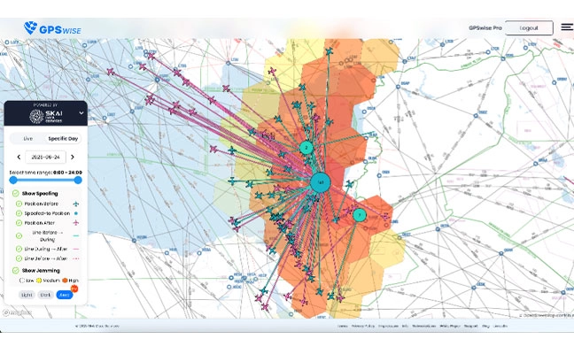
U.S. Department of Transportation (DOT) figures show incidences of GPS signal interference, such as jamming and spoofing, have increased significantly in both North America and much of Western Europe. Both commercial and military operations are affected, and ADS-B reports from Zurich University of Applied Sciences (ZHAW) cite up to 700 global GPS spoofing and jamming incidents taking place daily.
Events are particularly concentrated around war zones, with Lithuanian airspace alone recording more than 300 cases of GPS interference in March. The consequences have ranged from emergency diversions of civilian aircraft to, in at least one case, the downing of an aircraft. Other sectors reliant on precise timing and geolocation, such as communications and emergency services, also are being impacted.
Of course, it’s not just navigation; and a swath of industries rely on PNT signals. This includes secure and regulatory-compliant financial transactions, power grid synchronization, asset tracking, ensuring data integrity and coordinating workloads across global telecommunications and artificial intelligence (AI) servers.
How can PNT systems be made more resilient to this interference? What emerging technologies enable PNT systems to maintain operational capability in GPS/GNSS-denied, degraded or disrupted space operational environments (D3SOE)?
Interference Techniques
GPS interference comes in a wide variety of forms, and systems are susceptible because the signals from the satellites are faint by the time they reach the Earth.
Jamming is a brute force denial of service (DoS) attack, with a device transmitting a signal on the same L1 (1575 MHz), L2 (1227 MHz) or other relevant bands as the PNT satellites. Being nearer and stronger, these signals drown out the GPS information and prevent the ability to calculate a position, simply making GPS services unavailable.
Conversely, spoofing is a more sophisticated technique that mimics the structure of an authentic satellite signal but transmits falsified timing and positioning data. Similar to jamming, this relies on the spoofed signal being closer and more powerful than the legitimate PNT transmission and can either trick the navigation system into believing it is suddenly in a different position, or alter it slowly over time causing, for example, a ship or aircraft to deviate into an unsafe location.
These DoS and deception techniques are the major classes, but in addition to natural and accidental man-made sources, there also are multiple variations on spoofing techniques and methodologies:
Meaconing: Rebroadcasting of an authentic signal with a delay and shift in position to affect navigation systems.
Replay attacks: Like meaconing, but more targeted to financial transactions, fooling GPS-based time-stamping systems into accepting fraudulent transactions.
Data-level manipulation: Where false orbital data, clock corrections and GPS time is given in addition to the location data. These tend to be harder to detect and cause slow changes. They also can be applied to systems that rely on precise timing, such as financial networks and power grids.
PNT Resilience
PNT resilience standards are set out in the draft IEEE P1952 standard, which specifies technical requirements and expected behaviors for resilient PNT user equipment.
End users can test five behavior levels, which are defined within this standard to enable users to select a level that is appropriate based on their risk tolerance, budget and application criticality.
Photo: PNT Resilience Levels
Level 1 represents a basic ability to detect interference such as jamming, spoofing, or other disruptions, and alert users. Level 2 enables equipment to automatically recover to normal operation when the disruption is no longer present. In level 3, the equipment can maintain acceptable performance during the disruption. This capability is fortified in level 4 by leveraging multiple diverse sources or advanced mitigation techniques. Finally, level 5 enables the equipment to verify that the time or PNT information received is accurate.
Here in the U.S., the NIST 8323.1 Cybersecurity Framework for PNT also offers a comprehensive approach to assessing and mitigating PNT-specific cybersecurity risks. The DHS’ Resilient PNT Conformance Framework and CISA Federal PNT Services Acquisition Guidance are additionally important.
Countering Jamming
Traditional PNT systems are struggling to keep pace and meeting IEEE P1952 to tackle GPS interference requires a sophisticated, multi-source zero-trust architecture that never trusts, always verifies and authenticates, and goes beyond simple signal reception. For mission-critical systems, not only do threats need to be detected, but incoming data need to be validated and alternative sources for PNT incorporated, all within an intelligent sensor fusion system.
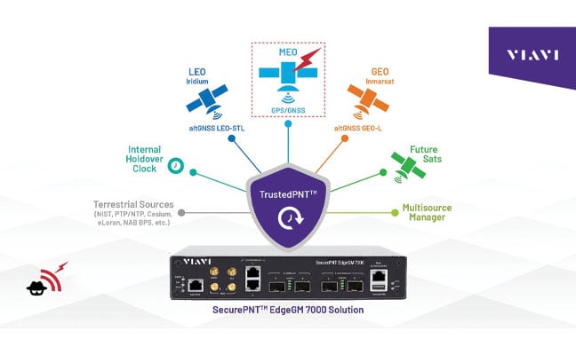
If we look first at the DoS jamming technique, here the issue is an inability to detect the medium-Earth orbit (MEO) GPS/GNSS signal in the presence of another more powerful signal.
It is possible, however, to reinforce L-band communications from GPS satellites, and look to stronger signals, notably from low-Earth orbit (LEO) satellites. While these have less accuracy for timing (GPS/GNSS: <15 ns vs 80 ns for LEO), they are significantly stronger (the Iridium LEO STL signal is 1000x stronger than GNSS) and are more resistant to jamming.
Countering Spoofing
In spoofing, the use of encrypted signals is vital.
GPS signals are open, unencrypted and should not be trusted blindly, and the use of alternative cryptographically secured alternatives is essential to ensure the signal’s origin is legitimate. For example, this is implemented on both the Inmarsat GEO and Iridium LEO satellites used in VIAVI’s SecurePNT and SecureTime services.
Sensor fusion also should be implemented to combine PNT data with information coming from onboard sensors such as inertial measurement units (IMUs) to identify inconsistencies — not just sudden large jumps but continual slight deviations.
Beyond these, navigation message authentication can be implemented, using a public key to verify the satellite-broadcast signature and prove the location, clock corrections and status being transmitted. This is already implemented by Europe’s Galileo Open Service Navigation Message Authentication (OSNMA) and makes it very difficult to data-level spoof these satellites.
While using receiver autonomous integrity monitoring (RAIM) techniques, calculate position with redundant satellites, excluding one satellite each time to check for consistency of results. ARAIM (advanced RAIM) uses the same technique, but applies it to multiple constellations, for example, GPS and Galileo.
Signal liveliness/consistency checks can be particularly effective against meaconing and replay attacks. These techniques examine the Doppler shift of the signal, with satellites having predictable and specific profiles that will differ significantly when compared to a ground-transmitted signal, which will have a near-zero Doppler shift.
Operating Under D3SOE
The above is a summary of the types of techniques that underpin VIAVI’s SecurePNT and SecureTime services.
SecureTime eGNSS GEO uses an encrypted L-band signal, transmitted from Inmarsat’s GEO satellites to create an enhanced timing service with GNSS authentication and anti-spoofing capabilities and provides sub-5 ns timing accuracy when installed on SecurePNT products.
Conversely, the SecurePNT systems implement multi-source receivers for GNSS backup and multi-band GNSS with GEO-L for outdoor antennas. The PTP grandmaster uses the latest sub-microsecond accuracy PTP protocol and the traditional millisecond range accuracy Network Time Protocol (NTP) to be compatible with virtually all standard IT equipment — also implementing high-speed 25G PTP Ethernet for connection to high-performance AI data center and AI-RAN networks and financial exchanges without creating bottlenecks.
Terrestrial sources, such as a network PTP feed and an optional atomic caesium clock, also can be used for synchronization to increase resilience in the event of a prolonged GPS outage. Nino De Falcis is an experienced business development leader with a strong background in the Global PNT market. Currently serving as the senior director of Global PNT Business Development at VIAVI Solutions since January 2024, he focuses on accelerating global business development and identifying growth opportunities.
Markus Irsigler, Sebastian Kehl-Waas, Carsten Stöber, Jürgen Dampf, Rohde & Schwarz GmbH & Co. KG
GNSS jamming and spoofing pose a significant threat to global security, as satellite-based navigation and timing systems are utilized in various application fields, including critical infrastructure, transportation, military operations and communication networks. These intentional interferences disrupt signals or deceive GNSS receivers, leading to navigation errors, loss of situational awareness and potential safety hazards.
Local, low-power jamming is often used to deliberately prevent GNSS-capable devices from recording their positions and being tracked. Such jamming devices, known as personal privacy devices (PPDs), are typically used to prevent fleet monitoring, concealing personal travel, or evading toll systems. Although mostly illegal, PPDs are fairly widespread and can pose a significant threat to GNSS availability, at least on a local scale.
On the other hand, larger-scale incidents are observed very frequently. Regional jamming often occurs in conflict zones to protect military assets or disrupt enemy operations. Jamming has also been reported near critical infrastructure. Spoofing is typically less frequent than jamming, but it poses a more concerning integrity threat when incorrect PVT data is used for navigation. Well-documented events include the (in)famous 2017 incident affecting ships in the Black Sea, where a spoofed GNSS signal led vessels to report incorrect positions. Jamming and spoofing also play an important role in the Ukraine conflict, where it is used to disrupt enemy drones, guided munitions, and navigation. Such events clearly highlight the vulnerability of GNSS-dependent systems and the need for robust mitigation techniques and strategies.
Against this background, testing how GNSS devices react to such threats has become more and more important, especially if they feature dedicated jamming detection and mitigation techniques. In such cases, the main test objective is to verify that these detection and mitigation techniques work as expected and that the GNSS receiver reacts properly and as expected in response to such attacks.
Categorization of GNSS Threats
Although jamming and spoofing can be considered the most critical threats, GNSS signals can be degraded in various other ways. Signal degradation effects can occur anywhere along the path from the GNSS satellite to the user. They can be caused by the transmitting satellite itself, usually in the form of hardware malfunctions, typically referred to as “evil waveforms.” They can also occur along the signal path in the form of ionospheric and tropospheric errors or scintillation effects, or they can be a result of the conditions in the vicinity of the GNSS user. This includes jamming, spoofing, RF interference caused by other signals, as well as signal obscuration and multipath caused by buildings or trees.
“Evil waveforms” can pose a significant threat to GNSS signal integrity, leading to large positioning errors. However, the occurrence of this effect is very rare and therefore not specifically considered in this article. There are also some atmospheric effects that have the potential to significantly degrade the quality of GNSS signals. Especially ionospheric and tropospheric scintillation due to temporal, fast-changing atmospheric conditions can cause rapid amplitude and phase variations, leading to reduced C/N0 or even loss of lock. Again, this does usually not happen every day and is therefore not discussed in detail below either.
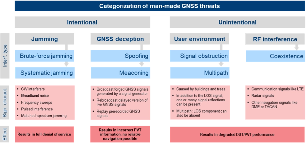
The most critical and common GNSS threats originate from interference signals that occur in the vicinity of a user receiver. Unlike system-inherent threats that originate from GNSS satellites or atmospheric conditions, these threats can be termed as “man-made” and categorized as shown in Figure 1.
Figure 1. Categorization of man-made GNSS threats. Credit: All figures provided by authors.
Jamming can be divided into two types of attacks. Brute-force jamming aims at completely blocking GNSS reception for a receiver by deliberately emitting interference signals like CW interferers, broadband noise or frequency sweeps with very high-power levels. As a result, the carrier-to-noise values will drop below the receiver’s acquisition and/or tracking threshold, and GNSS signals cannot be processed anymore. In contrast to such a simple jamming attack, where the attacker needs to have only basic knowledge about the GNSS signals (e.g. center frequencies and signal bandwidths), systematic jamming is a much more sophisticated attack, which can be further divided into
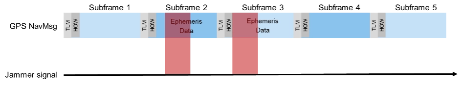
• Intelligent or smart jamming. The objective is to jam only a specific part of the navigation message (e.g. the ephemeris data section), so that the navigation message can never be fully decoded and the receiver will never be able to perform a position fix. All other parts of the navigation message remain unaffected, allowing signal tracking to continue for the receiver. Figure 2 illustrates this attack on the GPS L1 C/A signal.
Figure 2. An intelligent jamming attack performed on a GPS L1 C/A signal.
Smart jamming is much more complicated to implement for an attacker as the jammer must only be active during specific time intervals; this requires that the jammer is somehow synchronized with GNSS/Coordinated Universal Time. Moreover, the attack requires knowledge of the navigation message structure and what information the receiver needs to compute a position. Nevertheless, if done correctly, the attack is rather difficult to detect [1].
• Matched spectrum jamming. The objective is to generate a GNSS-like jammer signal with the same spectral characteristics as the real GNSS signals but without any valuable navigation information (i.e. the navigation message is missing). Matched-spectrum jamming is not straightforward, and to be effective, an attacker must replicate the GNSS signals for multiple visible satellites simultaneously, considering signal characteristics such as pseudo-random noise codes and, ideally, their correct Doppler shifts. In contrast to jamming, GNSS deception techniques aim to force the receiver to compute an incorrect PVT solution, compromising the integrity of GNSS-based navigation. The two basic methods are:
• Meaconing. This rather simple approach is based on rebroadcasting a delayed version of live GNSS signals. This can be realized by using a commercial GNSS repeater. Alternatively, previously recorded actual GNSS signals can be replayed.
• Spoofing. This includes generation and broadcast of forged GNSS signals. This is typically done using a GNSS simulator, but specialized, modified GNSS receivers combined with a transmitting unit can also be used. The simulated signals need to be self-consistent, i.e. a GNSS receiver must be able to compute a PVT solution based on the simulated constellation. Spoofing attacks can be rather simple, e.g. broadcasting high power signals that represent a different location than those of the receiver under attack. The aim is to force the receiver into a reacquisition process, tracking and processing only the fake GNSS signals. More sophisticated spoofing attacks are possible [2], but not discussed in this article.
Additionally, the PVT performance of a GNSS receiver can also be degraded by objects in the vicinity of a GNSS user, causing signal obstruction and reflections from buildings, trees, or the ground. Multipath can cause significant ranging and positioning errors. Multipath effects can hardly be avoided and must be seen as a permanent threat to GNSS signal quality.
Finally, other existing signals and services can interfere with GNSS, either because there is a frequency overlap (in-band interference) or harmonics from other signals fall into the GNSS bands (out-of-band interference). As an example, the upper part of the DME/TACAN band overlaps with a significant portion the GNSS L5 band. The effect of this type of interference on GNSS receiver performance can be analyzed by performing coexistence tests.
RX-Internal Detection and Mitigation Methods
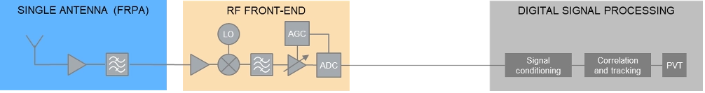
At least some of the threats discussed above can be detected and/or mitigated by the GNSS receiver. The capability of a GNSS receiver to detect and apply countermeasures to threats such as multipath, jamming or spoofing depends on the receiver’s availability of specific features and its basic architecture. Figure 3 shows the basic building blocks of a typical GNSS receiver with a single, fixed reception pattern antenna (FRPA).
Figure 3. Basic architecture of a FRPA receiver
The three basic building blocks are the antenna, the RF front-end and the digital signal processing section. The antenna is responsible for receiving the weak GNSS signals as well as for successive amplifying and band-limiting. It typically features a low noise amplifier (LNA) and a band-pass filter. The signals are then fed to the receiver front-end where the signals are amplified, down-converted to an intermediate frequency and converted to the digital domain. Part of this process is the automatic gain control (AGC) loop; the AGC acts as a variable amplifier, adjusting the power of the incoming signal and keep it constant over time. The sampled and quantized stream of IQ data is then fed to the digital signal processing section, where signal conditioning, acquisition and tracking, and PVT solution computations take place.
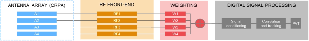
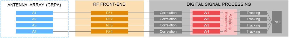
In contrast to using a single antenna with a fixed antenna pattern, some receivers use an adaptive antenna array, also referred to as controlled reception pattern antenna (CRPA). The idea is to weigh the signals received by each element according to dedicated optimization criteria. Typical optimization criteria are to minimize the signal’s output power towards a dedicated direction (“null-steering”), or to maximize the signal to interference or signal to noise ratio (“beamforming”). The underlying receiver architecture is more complex as signal weighting mechanisms must be added to the signal processing chain. These can be integrated before the digital processing block (“pre-correlation”) or implemented as an additional processing step between the correlation and tracking stages in the digital signal processing section (“post-correlation”). Both approaches are very effective in mitigating jamming and spoofing attacks, as they can either form a null in the direction of a strong jammer/spoofer or form beams towards the wanted signals from GNSS satellites, thereby de-weighting any unwanted signals coming from other directions.
Pre-correlation architecture of a 4-channel CRPA receiver
Post-correlation architecture of a 4-channel CRPA receiver
Within the processing chain of a GNSS receiver, there are different approaches and methods to detect and mitigate interfering signals, which are summarized in the following table:
AGC monitoring
●
●
Monitoring of the gain in the AGC loop. A sudden drop of the AGC gain can be an indication of an interfering signal; detection of high-power interferers; low-power spoofing attacks very difficult to detect
Spectrum monitoring
●
●
Detection of interferers and jammers above the noise floor; especially suited for detecting CW interferers. Not suited for the detection of matched-spectrum jammers, spoofers and meaconing attacks as their spectrum is typ. identical to the GNSS spectrum.
Frequency domain adaptive filtering
●
●
Dynamically identifies and suppresses unwanted frequency components (e.g., interference or multipath) by adjusting (notch) filter parameters.
Pulse blanking
●
●
Pulse blanking is a time-domain interference detection and mitigation technique used in GNSS receivers to detect and suppress short-duration, high-power pulses, typically caused by pulse jammers or Radar transmitters. Monitors the incoming signal power in short time windows and “ignores” this signal part in case certain power level thresholds are exceeded. Effective to mitigate pulsed jammers, not suited for multipath mitigation or anti-spoofing measures.
C/N0 monitoring
●
●
Monitoring over time and/or comparison against theoretical max. value; detection of all types of interferers; low-power spoofing attacks very difficult to detect
Time jump detection
●
●
Time jumps (backwards or forwards) are clear indications for meaconing or spoofing attacks.
PVT monitoring, incl. RAIM
●
●
Example: The computed position can be constantly compared against a known reference position. Not possible to distinguish between jamming/spoofing or other environmental effects like multipath. This also includes receiver-autonomous integrity monitoring (RAIM) schemes, that can be considered as a special form of PVT monitoring.
Doppler monitoring
●
●
Compare Doppler against theoretical/geometrical values; monitored Doppler profiles may show irregularities in case of an attack. Difficult to be separated from environmental or atmospheric effects.
CMC monitoring
●
●
„Code minus Carrier“ observable shows irregularities and increased noise in case of an attack. Difficult to be separated from environmental or atmospheric effects.
Signal Quality Monitoring (SQM)
●
●
Sampling of the correlation function using a few correlators; can detect distortions of the correlation function resulting from multipath, jamming or spoofing attacks.
Massive multi-correlator monitoring
●
●
Continuous, high resolution observation of the code/Doppler space. Can be done during signal acquisition and tracking. Can detect multipath, jamming, meaconing and spoofing attacks.
Derived Test Requirements
Based on the typical threat signal and attack characteristics, as well as the receiver-internal detection and mitigation methods discussed above, the test and simulation requirements listed in the table below can be derived. In addition to the requirements related to threat simulations (grey background), the table also contains “base requirements” for the simulation of realistic GNSS scenarios (blue background):
Testing: Methods, Setups and Challenges
The test methods, strategies and setups used depend on the architecture of the GNSS receiver being tested, the receiver features that need to be evaluated and the specific testing objectives.
A first categorization can be made by examining the origin of the GNSS signals being used for testing. The signals may come from real GNSS satellites and be used instantly and on-site (live GNSS testing) or recorded, stored, and played back in the lab (record/replay). Alternatively, testing can be done entirely in a lab environment using GNSS simulators. There are also hybrid test methods that will be discussed later in this article. In comparison to using real GNSS signals – either via live testing or the record/replay approach – using GNSS simulators in a lab environment offers significant benefits.
Simulation vs. Live GNSS Testing. One major drawback of using live signals is that the system conditions are often unknown at a given point in time, and – most importantly – they change over time. The locations of the satellites — and thus the geometric conditions — change as the satellites move along their orbits. Errors, such as atmospheric effects, are also time- and location-dependent. One of the most unpredictable error influences is multipath. The magnitude of multipath errors depends on a variety of different parameters, including the number of reflections, the distance between the reflection points and the antenna or the strength of the reflected signal. The latter is determined by the material properties of the reflecting surface. Both the geometric conditions and the material properties of the reflectors change or may change over time – the geometric conditions due to the permanent motion of the satellites and the reflector properties due to meteorological influences like rain, dew, or snow.
As a result, when using live signals, one must expect that the conditions change permanently and unpredictably and will never be the same for two distinct points in time. It is therefore very unlikely that two successive test runs can be performed under identical conditions. Repeatable testing, which is one of the most important test requirements, is impossible when using live GNSS signals.
Well-defined and controlled simulation conditions can only be ensured by using a GNSS simulator. A simulator typically offers fully customizable and repeatable scenarios (i.e., one and the same test scenario) that can be repeated as often as needed, producing the same signals with the same characteristics. Moreover, a simulator is often a more cost-effective and efficient solution, whereas using live signals would be time-consuming, complex, expensive or even impractical (e.g. test of airborne and spaceborne receivers).
The following discussion of typical test setups therefore focuses on the use of signal generators for GNSS testing. In terms of test scenarios, the focus will be on jamming, spoofing and coexistence testing. Testing against multipath influences is not specifically discussed below.
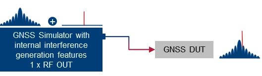
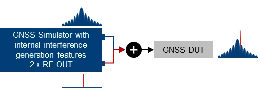
Basic simulator setups. The basic approach for testing against GNSS threats is to combine a “clean” reference GNSS simulation scenario with interfering signals and add the combined signals to the device under test (DUT). This basic concept can be implemented using two separate signal generators or an integrated solution that combines GNSS simulation and threat signal generation in a single instrument. Based on the architecture of the integrated solution (1 RF output vs. multiple RF outputs), GNSS and interfering signals are already combined internally, or GNSS and interfering signals can be fed to different RF outputs and combined with an external combiner before fed to the DUT.
Using two separate signal generators for GNSS threat testing. The interference generator (red) can either be a second GNSS simulator for generating spoofing signals or any other signal generator providing non-GNSS signals for jamming or coexistence tests.
Using a GNSS simulator with integrated interference generation capabilities. The signal generator features 1 RF outputs. GNSS and interfering signals are combined internally. An external combiner is not needed, but the dynamic range between GNSS and interferer (J/S) is usually limited.
Using a GNSS simulator with integrated interference generation capabilities. The signal generator features 2 RF outputs. GNSS and interfering signals fed to individual RF ports and combined externally. This requires an external combiner, but with the benefit that very high J/S ratios can be achieved.
Conducted testing vs. OTA testing. The basic setups introduced above only work if the receiver has dedicated and accessible input connectors to feed the antenna signal to the receiver’s front end. This is sometimes not the case, so that conducted testing is not possible and over-the-air (OTA) tests must be considered. A classic example of such DUTs is mobile phones, where no antenna connector is available, at least not without dismantling the device.
Testing such devices against interfering signals is still possible by using a shield box. The shield box has an RF input to feed in the combined GNSS and interfering signals. The signals are then retransmitted into the inside of the box and the DUT uses its integrated antenna to receive and process the signals coming from the GNSS simulator.
Using a GNSS simulator in combination with a shield box to test GNSS devices with integrated antennas.
OTA GNSS threat simulation using a shield box with 2 RF inputs and 2 transmit antennas. The GNSS signals and the interfering signals are fed separately (uncombined) into the shield box.
An alternative setup is to use a shield box with two RF inputs. In this case, the wanted signals and the interfering signals are not combined externally but are fed to the shield box via separate RF input connectors and transmitted to the GNSS DUT via separate transmit antennas.
Additional aspects and challenges must be considered when performing OTA tests using mobile phones as a GNSS DUT. This includes conducting a proper cold start, removing all preexisting navigation-related information from its memory, and disabling any other sensors that may contribute to computing the phone’s position, including any assisted GNSS services. This is typically not a concern for most standalone GNSS receivers that feature dedicated cold start procedures and usually have no other positioning sensors on board. On the other hand, initiating a real cold start for GNSS modules in mobile phones can be tricky. Just rebooting the phone does not necessarily work, and the availability of dedicated settings also depends on the phone’s operating system (e.g. iOS vs. Android).
Another challenge during OTA testing of mobile phones is how to assess and analyze the impact of any interfering signals on signal acquisition, tracking and positioning. This requires detailed analysis and monitoring features on the mobile phone, which are typically not a standard feature of the phone’s operating system. Specialized GNSS monitoring apps can be used instead. To get access to the data during the test, special screen mirroring apps can be installed on the mobile phone.
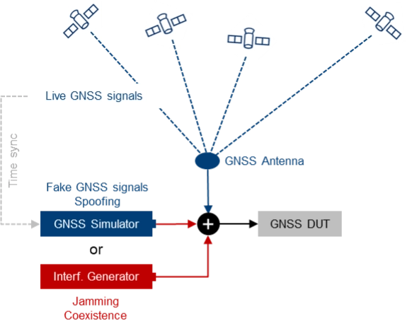
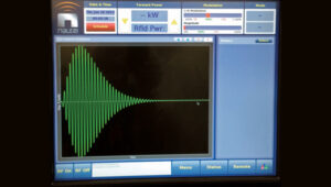
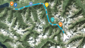
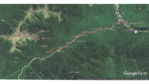
Testing with live signals. GNSS tests may also be performed in combination with live GNSS signals using already existing field infrastructure such as GNSS receivers installed at mobile base stations. A typical use case is to add one or several jamming/spoofing signals, or even an entire (stronger) “spoofing constellation” to an existing “live GNSS constellation” and test how the GNSS receiver reacts to such an attack. The typical test setup is illustrated in Figure 4.
Photo: Figure 4. The receiver’s response to interference is evaluated by introducing jamming or spoofing signals, alongside normal satellite signals using existing field infrastructure. This setup is often used to assess reactions to attacks.
This approach may be a good alternative to simulating everything with a GNSS simulator, as much more HW, i.e., more GNSS channels and more RF paths, are required with a simulator-internal approach. On the other hand, there are also some challenges associated with this test method, e.g., the signal generators, which need to be operated in a field environment. Moreover, for more sophisticated spoofing attacks, a prerequisite is the capability to time-synchronize the GNSS simulation with the live GNSS constellation.
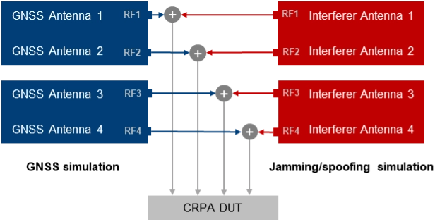
CRPA testing. For testing GNSS receivers with multiple antenna inputs, particularly CRPA systems, several RF sources/paths need to be combined and synchronized. The following illustration shows a possible setup for testing a 4-channel CRPA receiver against jamming or spoofing attacks. It is based on the 2-path architecture introduced above. It consists of two signal generators for generating GNSS signals for each antenna (left part of the setup) and two signal generators for generating the jammer/spoofer signals (right part of the setup). GNSS and interfering signals are combined per antenna element and fed to the RF inputs of the CRPA receiver under test.
For CRPA testing, generating phase-coherent signals is a must, i.e., it must be ensured that the phase relations between the GNSS signals and between the interfering signals represent the actual geometrical conditions and, above all, remain consistent throughout the simulation. To achieve this, a common LO signal needs to be used for generating the GNSS and interferer signals in all signal paths.
Another challenge is related to calibration. To correctly simulate the directions of the satellite signals and the interference signals, the test system must be calibrated at the RF interface to the DUT with respect to amplitude, phase and propagation time. This means that the amplitude, phase and propagation time differences between the individual RF paths, resulting for example from cables orRF components, must be compensated.
Rohde & Schwarz Solution
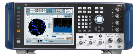
With GNSS test solutions from Rohde & Schwarz, all the relevant requirements for testing GNSS receivers against GNSS threats can be addressed. Available test solutions range from simple, single-channel, waveform-based signal generation with limited simulation time up to multi-frequency, multi-constellation GNSS simulators with 2 RF outputs, hundreds of GNSS channels and internal threat simulation capabilities, including non-GNSS signals for jamming and coexistence tests. For these advanced GNSS tests, the R&SSMW200A high-end vector signal generator is the ideal choice. It can be equipped with a multitude of GNSS options and feature sets.
Photo: Testing against GNSS threats with the R&S SMW200A
Jammer simulation. There are several ways to generate jamming and coexistence signals with Rohde & Schwarz signal generators in general and especially with the R&SSMW200A. Simple interference signals like noise or a CW interferer can be generated by using an optional integrated noise generator. For coexistence testing, the instrument can be equipped with signal generation capabilities for various standard-conforming communication signals, such as LTE. Customized interferer signals in the form of waveform files can be created by external software tools like MATLAB or Python and replayed by the instrument.
Customized jamming signal as well as entire jamming and coexistence scenarios can also be created using the R&SPulse Sequencer. The software allows to generate typical simple GNSS jamming signals like CW interferer, frequency sweeps, or pulsed interferers, but also complex jamming scenarios with consideration of moving interference sources and moving GNSS receivers, user-defined antenna patterns and scans. Depending on the signal characteristics, the jammer and receiver positions and the antenna arrangement, the software calculates the correct amplitude, phase angle and signal propagation times for the jamming signals.
Further reading
[1] Curran, James T. et. al. (2017): A look at the Threat of Systematic Jamming of GNSS, InsideGNSS, September/October 2017
[2] Dovis, Fabio et. al. (2015): GNSS Interference Threats and Countermeasures, GNSS Technology and Application Series, Artech House, 2015
The intriguing paradox about the information age is that it relies on semiconductor chips, which are fundamentally made from sand (silicon dioxide) — the most tangible and seemingly infinite resource on Earth. Yet, in 2023, the global digital storage capacity reached 110 zettabytes (110 followed by 21 zeros), which is a staggering figure; in fact, it is 15,000 times more than the number of grains of sand on Earth and it’s doubling every three years. The information age is suffering from excess information. Data is consuming the universe.
The velocity and quantity of information are overloading the ability to process it. This causes data-driven decision-making systems to fail. The limiting factor is human cognitive capacity to select, prepare and process the data, plus the ability to analyze it for meaningful insights. It is reminiscent of the early days of the Corona satellites of the TALENT KEYHOLE (KH) mission series that began in the 1950s during the height of the Cold War.
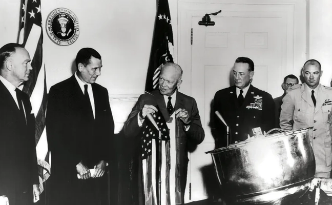
Understanding activities behind the Iron Curtain was critical for national security. The KH satellites were expensive to launch and had short life spans. They used rolls of wet film dropped from space and captured by specialized aircraft with hooks to catch the canisters in mid-air. The low-resolution images (3 m to 5 m per pixel) were processed manually in darkrooms. Teams of 100 specialists, using razor knives and scotch tape, meticulously pieced together image strips into massive mosaics spanning several square meters. Working around the clock, assembling the full image would take up to five days, with subsequent analysis requiring another week. In total, from catching the film canister to delivering a final intelligence report, it took 17 days — a testament to imagery intelligence in the industrial era, characterized by massive operations demanding significant time and manpower, but it was too expensive and unsustainable.
Photo: PRESIDENT EISENHOWER awards Capt. Mitchell, USAF, C-119 pilot, the Distinguished Flying Cross for the first ever capture of
a film cartridge dropped from space, in a photo circa 1960. cia.gov/resources/csi/static/corona.pdf
“We live in a world where there is more and more
information, and less and less meaning.”
— Jean Baudrillard,
“Simulacra and Simulation,” 1994
In 1976, the technological landscape shifted dramatically with the launch of the KH-11 satellite, which could transmit 15 cm resolution images digitally to ground stations and was capable of distinguishing objects as small as a dinner plate. The satellite dramatically compressed intelligence-gathering timelines. Processing and analysis time decreased from 17 days to mere hours. The first digital image was shown to President Carter. That first image is believed to be of ongoing tensions in the Middle East, but it symbolized more than the triumph of technology; it represented a fundamental shift marking the end of the industrial era and ushered in the information age.
Advancements in imagery were paralleled by developments in mapping, driven by the need for accurate spatial referencing. Various technologies throughout the 1970s offered partial solutions, but a solution did not happen until 1981 when Esri introduced Arc/INFO, a breakthrough geographic information systems (GIS) software that could operate on minicomputers instead of huge mainframes. That formed the basis of modern spatial analysis and visualization technologies; coming together with digital imagery is what allowed the information age to overtake the industrial era.
In 2025, a similar technological transformation currently is underway. As the amount of information overwhelms existing systems, artificial intelligence (AI) is emerging as the solution. The information age is transforming into the intelligence age, where big processing meets big data. Advanced algorithms, machine learning and large language models (LLM) can swiftly and efficiently handle vast amounts of information. So, with data being the new oil, AI is the refinery.
TheEsri Federal GIS Conferencein February could have been promoted as the “Dawn of GeoAI” conference. The term Geo AI is a subset of Spatial AI, and it is in its infancy. Esri is incorporating AI into many of its applications. Companies at the expo were teasing Spatial AI solutions in their products and services.
What is Spatial AI?
When the transformative power of AI is combined with spatial information systems, magic happens. Value is created that did not exist before.
Spatial intelligence is the ability to think, visualize and understand in three dimensions. It is one of the primary types of intelligence. Currently, Spatial AI is capable of interacting with analysts using natural language to build models and perform tasks. Similar to so much else happening with AI, its capabilities are increasing rapidly.
Photo: A CORONA SATELLITE image of Moscow captured May 28, 1970, as part of the TALE…
With iterative learning, the AI repeats a task millions of times on various training data to perfect its abilities, running through different scenarios multiple times with different datasets while completing multiple tasks. The AI quickly learns and can eventually surpass humans. This makes AI a super tool.
Combine that capability with AI’s ability to access and infer an entire compendium of knowledge on a subject. The AI is able to ingest text, images, audio and video in minutes, and then reason and understand them all within the context of the parameters provided. Through its own AI agents, it will automatically run functions to garner insights, and then communicate those results through data visualizations, text, audio and natural speech. Spatial AI is an evolved form of AI able to understand data in the context of space and time within the body of knowledge it can access. It will monitor everything in real time to identify anomalies and hidden patterns and provide deep insights. It doesn’t just solve the information overload dilemma for data-driven decision-making, but it enhances it far beyond expectations.
The Coming World of AI Assistants
The future is already here. Reality is approaching science fiction at warp speed. A person living 100 years ago would only be able to understand the world of today as magic; and likewise, the world 20 years from now will appear magic to us.
Interfacing with a Spatial AI system is similar to the multi-dimensional world we already exist within. Flat screens, keyboard and mouse will be secondary tools behind natural language and natural gestures and immersive experiential environments. The Spatial AI- enabled world will blur the lines between what is virtual and what is real. Jobs, businesses and the economy already are transitioning. The most well capitalized businesses are investing in this new technology.
One of the industries at the forefront is healthcare. Imagine you are a neurosurgeon. Your patient has a glioblastoma identified by the MRI/CT scans uploaded into the Spatial AI Medical Assistant called SAIMA (pronounced Sāmă; when speaking with the system, you call it “Sammi”). The MRI/CT scans show a 3D model of the patient’s brain, highlighting the glioblastoma in red. Placing the integrated augmented reality (AR) glasses on, you can zoom in on the glioblastoma to see the extent of the growth and view it from any angle. This helps formulate a surgery plan. The patient’s medical records are in SAIMA along with the corpus of knowledge about glioblastomas. SAIMA is regularly updated with the latest algorithms and models. After reviewing the preliminary data, you have SAIMA run the spatial analytics and all the applied functions on the data. It takes approximately 35 minutes to complete. During that time, you review the SAIMA updates and go to lunch. You receive a text message from SAIMA after it completes its processing, letting you know it is finished without encountering any issues. SAIMA works with a system called VisAR, which is a precision surgical navigation system. After returning to your office, you put on the VisAR glasses to begin the review. Sammi begins by showing you the glioblastoma and pointing out it is a large, heterogeneous mass located in the frontal lobe and appears to be 4 cm to 5 cm in diameter, in an irregular shape with nodular and cystic components. As it goes through the review, it zooms in and rotates the 3D image, highlighting the exact area being talked about. You interrupt Sammi during this review and ask if the patient has been experiencing motor function issues since the tumor is in the frontal lobe, and you continue to probe further in a natural conversational tone as you delve deeper into the analysis. The conversation between you and Sammi is recorded and added to the file.
The review with Sammi takes several hours, during which a high-confidence surgery plan is developed that you will present to the multidisciplinary tumor board, who will further query SAIMA. This thorough process ensures the best results and further trains SAIMA about glioblastomas, which will be used for a post-surgery debrief and for insurance purposes. Following a successful board meeting, SAIMA proceeds to reserve the operating room, schedule the patient, and create a detailed surgery plan with specific duties and exact times for each member of the surgical team. This plan is then disseminated to all members of the surgical team and preoperative staff. A detailed surgical procedure file is generated, which serves as a navigation file, similar to Waze or Google Maps, providing step-by-step instructions to guide the surgery. This file will be loaded into ROSA (Robotized Surgical Assistant), a high-precision robotic surgeon.
On the day of the surgery, you wear special Bluetooth gloves that are synced with the SAIMA/VisAR glasses and ROSA. In real-time, magnified between 15x and 40x, you observe ROSA surgically removing the cancerous tissue. Overseeing the process, you see a tumor that has spread beyond the original CT/MRI scan and zoom-in on the tumor, and you take control of ROSA to manually remove the tissue. The surgical system uses a “differential engine” concept to scale down the surgeon’s movements to match the magnification level of the procedure, allowing for precise and delicate tissue removal. This means that the surgeon’s natural movements are reduced to a smaller, more precise scale, enabling accurate and intricate procedures. For example, a 1 cm movement by the surgeon might be translated into a 0.1 mm movement of the robotic arm, allowing for high-precision work. The system is dependent upon a high-level of spatial intelligence to make those calculations in real-time.
Afterward, you return the surgery back to the automated control of ROSA to follow the surgical procedure file plan. Throughout the fully immersive procedure, you speak with Sammi in a calm, natural language and responsive manner.
The patient, a married middle-aged father of two, not only survives but thrives because of the accurate analysis of SAIMA and the precision of ROSA, with you overseeing the entire process. The Spatial AI-based surgical system allows you to do what you wanted to do as a neurosurgeon and save people’s lives.
Nothing is Permanent Except Change
Breakthrough innovations, such as the internet, have changed the world. Spatial AI is going to do the same. These technologically driven schisms are huge opportunities. One can only speculate how it will alter the future. Once a technology takes hold, and it becomes obvious there is no going back, its adoption will accelerate, and in those moments, careers make exponential leaps. Those in front of it will make substantial gains. Position yourself accordingly. Learn about Spatial AI and Geo AI. Carve out your own specialty, such as Spatial AI/AR (augmented reality), Spatial AI/VR (virtual reality), Spatial AI/XR (mixed reality), and Spatial AI/FMV (full motion video). The future is yours to imagine.
Photo: William Tewelow
WILLIAM TEWELOW is a designated Geographic Information Systems Professional. He has a master’s degree in Organizational Leadership with a focus on Performance Management, a bachelor’s degree in Intelligence Studies focused on geospatial intelligence, and an undergraduate degree in Geographic Information Technologies. William retired from the Federal Aviation Administration in 2025 after 16 years in various roles supporting geospatial information for aviation operations in the national airspace. He is a graduate of the management fellowship Program for Emerging Leaders where he served on special assignment to the Department of Transportation, leading a national strategic geospatial initiative under the authority of the White House Open Data Partnership.
Saying the government must focus on “delivering an operational resilient positioning, navigation and timing (PNT) system for the United Kingdom as soon as we can,” the British Science Minister, Lord Patrick Vallance, announced several initiatives in his opening remarks to the Royal Institute of Navigation’s UK PNT Leadership Seminar on Nov. 20, 2024.
Among them was a funding increase for the National Physical Laboratory’s National Time Centre (NTC) project from £30 million ($38 million) to £62.7 million ($79 million) and a plan to have NTC and the first of the nation’s new eLoran towers at initial operating capability (IOC) by January of 2027.
Plans for all efforts beyond next year were necessarily “subject to spending review.”
Still, seminar attendees were gratified to hear the minister’s endorsement of the 10-point PNT policy framework published by the previous administration in 2023 and his commitment to operationalizing it with implemented systems.
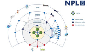
Shabana Haque, Ph.D., head of the United Kingdom’s National PNT Office, also addressed the seminar and elaborated on the government’s actions to date and plans moving forward. She also discussed efforts toward developing quantum technologies and how all the capabilities would be incorporated into a coherent architecture.
Photo: RNT Foundation
Clocks
The United Kingdom recognizes time and timing as the most fundamental component of the PNT utility. Its NTC R&D program, run by the National Physical Laboratory (NPL), has been up and running since 2019. Its primary objective is to create “…a resilient UK national time infrastructure through the building and linking of a new atomic clock network distributed geographically in secure locations.”
Five years later, that program is coming to an end. Plans are in the works for the next phase of the NTC program, which includes developing a national timing infrastructure and supporting a new timing ecosystem — one that includes two-way satellite-time transfer (TWSTT), eLoran and the country’s legacy MSF radio time service. The industry will have a valuable role in the architecture of time distribution and providing value-added services while accessing highly resilient and well-authenticated core government time infrastructure.
As a result of NTC work to date, traceable time and frequency signals can now be accessed by industry and academia from three NPL nodes dispersed across the United Kingdom. They are at the University of Strathclyde in Scotland, the University of Cranfield in the Midlands and the University of Surrey in the south.
eLoran
eLoran also features prominently in the United Kingdom’s PNT plans. Britain operated Loran-C as part of the Northern European network until the end of 2015. For the last year of that, differential stations were deployed along the United Kingdom’s eastern coast and maritime operations based on eLoran were authorized.
On Jan. 1, 2015, and despite British pleas to the contrary, other northern European nations terminated Loran broadcasts in favor of Galileo. The United Kingdom has continued to operate its single eLoran transmitter as a national time signal. Plans call for additional transmitters to enable eLoran navigation across the nation and its adjacent waters within the next two years.
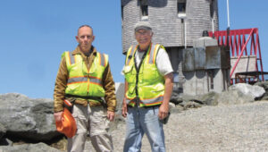
UrsaNav Loran monitor on Nautel equipment. (Photo: RNT Foundation)
The UK government has been working with several partners to advance its understanding and plan for the implementation of an eLoran capability. Haque highlighted work with the European Space Agency’s NAVISP program, resulting in the British company Roke developing an eLoran antenna for handheld devices.
She also discussed integrating the NTC’s clock and fiber network with eLoran signals and developing GNSS/eLoran receivers.
Many were particularly interested in an “eLoran Effectiveness Report” that the government commissioned and received from the General Lighthouse Authority’s Research and Development (GRAD) team. GRAD has extensive experience with the technology, having operated and evaluated the differential eLoran system along Great Britain’s east coast.
In a related move that helped signal the United Kingdom’s commitment to the technology, the Ministry of Defence issued a Request for Information (RFI) in September 2024 about a deployable eLoran capability. The RFI indicated that the document was a prelude to an acquisition.
Quantum research
The United Kingdom has invested more than £1 billion ($1.3 billion) into quantum research, which has the potential to contribute to PNT with better timekeeping and inertial and gravimetric sensing.
One aim of the quantum research program is to develop “…new navigation and timing systems to provide resilience and improved accuracy in the event of the denial of satellite systems.” A specific goal is to deploy quantum navigation systems, including clocks, on aircraft by 2030.
The program began in 2014 and has seen a significant increase in 2024 with the establishment of five quantum hubs nationwide. The hub at the University of Glasgow focuses on resilient PNT systems for national security and critical national infrastructure.
Policy and coordination
Minister Vallance and Haque also discussed two important non-technology themes.
The first was that the United Kingdom’s PNT office is fully funded, staffed, and very active. It was created last year as a cross-government effort and includes representation from the Ministry of Defence. In addition to pushing the nation’s PNT efforts forward, the office has been engaged with numerous other governments, including those of the United States, Canada, Australia, New Zealand, Europe, Japan and Korea.
USCG Loran tower circa 1995. (Photo: RNT Foundation)
Second, while the PNT initiatives are necessary for the nation’s resilience and security they will also be a source of economic benefits. This goes beyond enabling the British economy to function during local and potentially widespread GNSS disruption events. As the nation develops the technology stack to support its own resilient PNT architecture, along with enabling and supporting policies, resilient PNT devices and services will become marketable to others.
A sovereign PNT capability that can both stand on its own and cooperate with GNSS is becoming increasingly attractive to many nations. Being able to source such a capability from a respected and trusted ally such as Great Britain could make acquiring and implementing such a system much easier for many.
The UK Science Minister also praised the RIN’s work and publication of a series of tools to help explain PNT and the need for resilience to those outside the community. The tools also will help organizations evaluate their readiness for GNSS disruptions.
Available from the RIN’s Resilient PNT Portal, they are
A PNT explainer that outlines risks from over-dependence on GNSS and provides links to other informative resources.
A best practices “placemat” describing a “Prepare, Act, Recover” framework for PNT disruptions.
A PNT resilience checklist for organizations to use to self-evaluate their risk from GNSS disruptions.
The RIN recommends PNT experts use these tools working with customers, suppliers, and partners and act as a “guiding hand.”
The RIN sees these all as a “phase 1 release.” Feedback on the tools is encouraged and should be sent to [email protected]. The RIN team is eager to know what works and what could be improved, as well as to receive suggestions for other efforts.
As a “learned society,” the RIN has a significant influence on government policy and direction. This was recognized by Lord Vallance, saying, “The Royal Institute has played a really important role in recent years to highlight the PNT opportunity and risk, to provide expertise, and to work with government on solutions.”
The RIN’s director, John Pottle, and RIN Fellows Ramsey Faragher, Guy Buesnel and Andy Proctor were all recognized during the seminar for their contributions to the organization’s resilient PNT efforts.
UK leading the west
While China is in the final stages of establishing a nationwide clock system integrated with eLoran and signals from space, and South Korea is following suit, the United Kingdom seems to be the only Western nation in the process of establishing a coherent and resilient national PNT systems-of-systems architecture.
Some nations have substantial fiber timing networks, Europe seems to be on the path to a timing backbone, and the United States has three eLoran transmitters on air. However, none have announced the type of integrated plans the UK has published.
When asked about this, one UK PNT technology and policy expert opined that his nation is so far ahead of Europe and the United States because “we are unencumbered by having our own GNSS.”
His idea is that GNSS involves a lot of time, effort and money. The kind of financial and emotional commitments needed for these huge projects makes it hard for many to come to grips with the limitations and vulnerabilities of GNSS and the need to implement complementary systems. Both government officials and GNSS industry lobbyists may tend to resist such efforts, he said.
Concerning the UK government’s investment in OneNav, he said it is still possible that the United Kingdom might also pursue a space-based capability. Rather than establishing the capability on its own, in his opinion, the government will be much more likely to look for a commercial subscription service.
“We will access GNSS when we can trust it, and may pay for other signals from space,” he said. “But we want a sovereign capability for the United Kingdom, and the future of resilient PNT is terrestrial.”
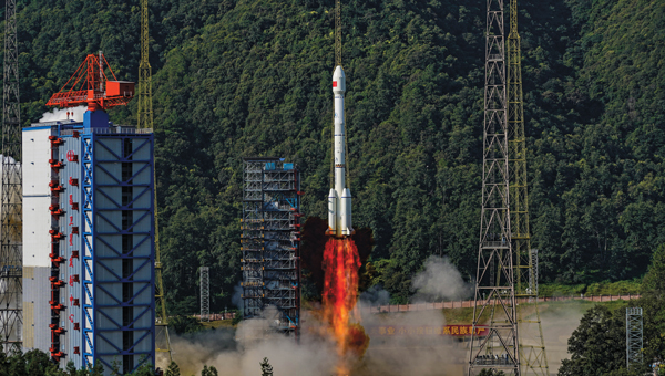
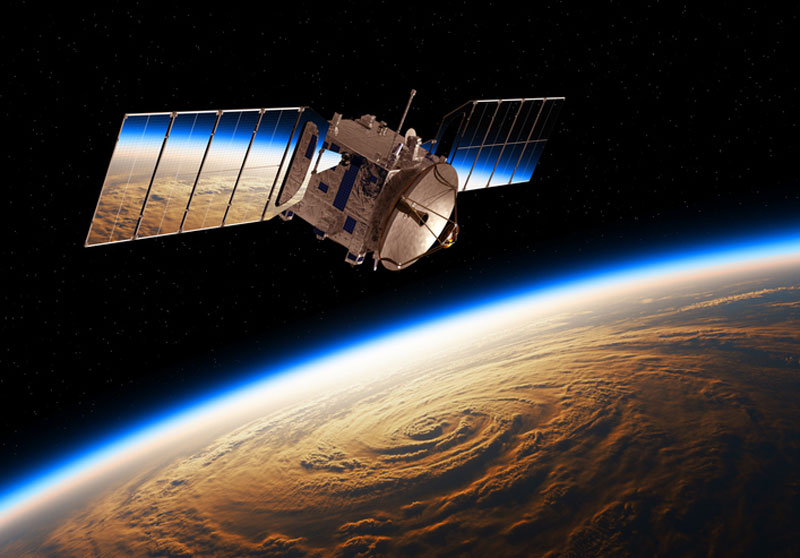
Successful launch of the 59th and 60th BDS satellites on Sept. 19, 2024. (Photo: International Cooperation Center of China Satellite Navigation Office)
Upholding the principles of “superior construction, excellent management, and substantial development,” the BeiDou Navigation Satellite System (BDS) implements multifaceted strategies to ensure uninterrupted and stable system operations and services, with its backup satellites launched into orbit as per the scheduled plan in 2024. Concurrently, research on next-generation BDS technology upgrades and related technological trials for integration with low-Earth orbit (LEO) positioning, navigation and timing (PNT) systems are vigorously promoted, further enhancing international collaboration and propelling the continuous advancement of BDS in the new era.
1. System operation and services
All figures provided by the author.
BDS currently consists of 45 operational satellites in orbit, delivering services through 15 BDS-2 and 30 BDS-3 satellites. Since May 2023, five BDS-3 backup satellites have been launched to bolster system resilience.
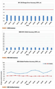
According to the monitoring data from the International GNSS Monitoring and Assessment System (iGMAS) and the International GNSS Service (IGS) in 2024, BDS achieves a service availability of 100% and exhibits a single satellite signal continuity of 99.991% per hour, with signal-in-space accuracy surpassing 0.9 meters (95%), broadcast ephemeris accuracy surpassing 0.2 m (95%), single frequency three-dimensional positioning accuracy of the B1C signal better than 6 m (95%, global average), and the B1C/B2a dual-frequency three-dimensional positioning accuracy superior to 3 m (95%). The timing accuracy is noted to be better than 10 ns (95%). The performance of the BDS PNT service has consistently met all performance requirements.
Figure 1 illustrates the spatial signal accuracy of the BDS B1C signal. Figure 2 presents the broadcast orbit accuracy of the BDS B1C signal. Figure 3 showcases BDS’ global positioning accuracy for both single-frequency and dual-frequency.
Through the BeiDou Satellite-Based Augmentation System B1C (BDSBAS-B1C) and the BeiDou Satellite-Based Augmentation System B2a (BDSBAS-B2a) signals, BDS offers single-frequency BDSBAS service that meets APV-I requirements and a dual-frequency multi-constellation service that meets CAT-I requirements for China and surrounding regions. The ionospheric grid model has been persistently refined to enhance the performance of the satellite-based augmentation services at the peripheries. Evaluation results reveal that the BDSBAS service attains a single-frequency positioning accuracy of 1.29 m (95%) horizontally and 1.99 m (95%) vertically, and a dual-frequency positioning accuracy of 0.77 meters (95%) horizontally and 1.41 m (95%) vertically.
BDS disseminates precise orbit and clock difference corrections and inter-code biases via the precise point positioning (PPP)-B2b signal, providing PPP services to China and surrounding areas. Evaluation results indicate that the BDS-only precise point positioning accuracy is 0.16 m (95%) horizontally and 0.22 m (95%) vertically, with a convergence time of less than 20 minutes.
In 2024, building upon its PNT services, BDS actively offers diversified specialized services, including regional short message communication, global short messaging, and international search and rescue. The number of user terminals for regional short message communications continues to grow. Based on inter-satellite links, global short messaging services can provide users with global random-access capabilities. These services have been applied in projects such as the Einstein Probe mission, the SVOM satellite in collaboration with France, and gravitational wave detection satellites, achieving instant return of global detection data. While six medium-Earth orbit (MEO) satellites are equipped with international maritime search and rescue payloads, the BDS return link enables transmission with a communication delay of less than 12 seconds, and a success rate of 96.82%, suitable for distress alert feedback, disaster information broadcasting and other multi-application scenarios.
The stable BDS operation ensures the consistent and rapid improvement of application industries and the expansion of application scenarios. In 2023, the total output value of China’s satellite navigation and location-based service industries reached more than RMB 530 billion, marking a growth of more than 7% compared to 2022.
2. System construction and development
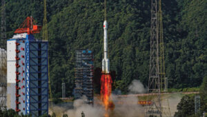
In May 2023, a backup geostationary orbit (GEO) satellite was launched, followed by two additional MEO backup satellites launched in December 2023, featuring upgraded global short message communication capacity and enhanced intelligent payload technologies. These backup satellites have successfully completed in-orbit testing and are now ready to provide services as needed. In September 2024, another pair of MEO backup satellites, equipped with innovative atomic clocks and a new type of inter-satellite links, were deployed. These backup satellites improve system reliability and service performance and facilitate experimental validation for next-generation satellite technology upgrades.
To continuously enhance system service performance, BDS has developed precision and stability enhancement plans for both the ground control system and the in-orbit satellite support system. Efforts include intensifying satellite-based and ground-based multi-source data fusion analysis, conducting regular assessments of constellation and ground system statuses, and improving fault automatic diagnosis, response efficiency, and intelligence capacity.
China is actively promoting the integrated development and experimental validation of BDS and LEO satellite navigation augmentation systems. Leveraging several test satellites within the under-construction LEO constellation, experiments including GNSS+LEO FPPP have been conducted. Results demonstrate that GNSS orbit determination accuracy is better than 5 cm (1σ), and clock error determination accuracy is superior to 0.15 nss (1σ). With signal enhancement from two to three LEO satellites, PPP positioning accuracy reaches 0.3 m with a convergence time at the minute level, thereby enhancing high-precision service performance and reducing PPP convergence time.
In May 2023, China successfully launched the first BDS-3 GEO backup satellite. (Photo: International Cooperation Center of China Satellite Navigation Office)
3. International coordination and cooperation
China has been deeply involved in international satellite navigation. Since 2023, China has actively participated in a series of events under the United Nations framework, including the ICG-17 and the United Nations Workshop on the Application of Global Navigation Satellite Systems, contributing to the global advancement of satellite navigation. China has engaged in deep collaboration with system providers from the United States, Russia and the European Union to facilitate compatibility and interoperability, covering navigation signal structures, time systems, coordinate frameworks, test and assessment. Meanwhile, discussions are held with regional navigation satellite systems and emerging systems on topics of mutual interest, such as high-precision services and emergency alert services. In 2024, the BDS timing service was officially included in the Time Bulletin by the Bureau International des Poids et Mesures (BIPM), signifying international recognition of the ability to provide precise and reliable standard time services globally.
China continues to expand its international partnership with BDS. In recent years, events including the BDS/GNSS Global Partner Forum, the China-Africa BDS Cooperation Forums, the China-Arab States BDS Cooperation Forums, the China-Central Asia BDS Cooperation Forums, the International Training Workshop on BDS Technologies and Applications in the Belt and Road Countries and Regions and the International Summit on BDS Applications have been held to share the benefits of BDS/GNSS applications globally.
BDS will continue to uphold the vision of “a first-class navigation satellite system developed by China and dedicated to the world.” It will make every effort to ensure the stable operation, steady upgrades, and advancements of the system, as well as in-depth research in technologies such as low-orbit PNT and lunar PNT, furthering the commercialization, industrialization, and internationalization of BDS applications
HERE Mapmaking allows users to create detailed interactive maps of private sites, outdoors and indoors. This includes sites not covered by public maps, such as warehouses, yards, farms, mines and ports. (Photo: HERE Technologies)
Location-based services (LBS) are software services that allow apps to function as intended by collecting geodata and providing users with pertinent information based on their location. Examples include search, navigation, transportation, entertainment, social networking, marketing, shopping, remote health monitoring, parental control and asset tracking. These services rely on mobile networks to transmit and receive data and connect to analytics software operating on a remote server to process and send relevant data to the user.
They have existed since the early 1990s but only gained traction after May 2000, when the U.S. government stopped degrading the civil GPS signal (a policy known as Selective Availability). This increased GPS accuracy by an order of magnitude overnight, making many more civilian applications possible. Since then, software engineers and developers have been designing LBS and building location-aware apps to deliver contextually relevant experiences to end users.
Adoption of LBS has been extensive because these services produce quality geodata with personal, spatial and temporal dimensions. Although most people think of GPS when they think of geolocation, LBS is the unsung hero powering location-based online activities.
LBS combines various positioning solutions — including GNSS, and trilateration from cell towers, Wi-Fi hotspots and other signals of opportunity — to collect the most accurate location data possible outdoors and indoors.
LBS capitalizes on cell tower signals and Wi-Fi networks to gather geolocation when satellite reception is poor or entirely blocked, such as in urban canyons and underground parking lots. Although these alternative positioning systems are not as accurate as GNSS, the approximate location information they provide is generally sufficient for the purpose of the services — such as to find a store in a mall or a grader on a construction site.
Monetizing LBS
The advent of Web 2.0 and the mobile revolution have empowered Internet users to interact with their immediate physical world digitally. Suddenly, finding the shortest route in a new city, choosing from numerous restaurants for lunch, searching for the nearest gas station, consuming relevant stories on social media and snagging limited-time coupons and discounts are all possible at the tap of a button.
Physical location has become instrumental in personalized online experiences, hence the need for location-aware apps. Software vendors have embedded seamless data collection capability into electronic devices, creating a business ecosystem surrounding people’s location details.
Geodata collection is effortless but permission-based. While laws governing LBS vary by jurisdiction, they generally require users to accept an LBS-supported app’s privacy policy, which spells out what it does with location data. Additional steps include running the app and activating the device’s location service in the settings or approving on-screen permission request prompts before tracking can begin. Such a process helps ensure that users are aware of geodata collection and understand its inherent risks.
In the early days of LBS, tech pundits argued that marketers would capitalize on the technology to bombard consumers with ads. Those were prophetic words — many heavily used apps today use LBS. The tech companies behind them leverage geodata to create valuable products and sell advertising space through their platforms.
Although it is challenging to count the number of ads populating sites and apps, rough estimates say that average Internet users see thousands daily. It does not feel this way because in-your-face ads are no longer the norm in cyberspace — the discrete ones are, and they work. Experts predict that the $96 billion location-based advertising market will expand at a compound annual growth rate of 15.1% from 2023 to 2030.
Unsurprisingly, tech titans enjoy the lion’s share of digital advertising revenue. In the United States, Google, Meta and Amazon collectively accounted for about 62% of the pie in 2023.
Other corporate models exist to monetize geodata. The LBS-based game Pokémon Go is free to play, so it can grow a massive user base quickly and earn profits through in-game purchases. In addition to living off ad revenue, Tinder uses freemium pricing for its geographic matchmaking business and simplifies socialization and dating for paying subscribers.
Moreover, Uber, Lyft and Airbnb swell their coffers through commissions, earning a cut for every transaction on their platforms. Big box store Target blends indoor mapping, beacon technology and geofencing to enable shoppers to pick up their orders at the nearest store’s entrance when they arrive. Aside from mostly Silicon Valley titans that have developed and gainfully used LBS for themselves to increase their valuations, others have decided to help non-tech enterprises innovate by integrating location-based technology into their operations.
Democratizing Mapmaking
Disrupting cartography is a low-hanging fruit. Humans have been drawing maps for millennia, yet many areas remain unmapped. Public maps usually exclude private locations. When they are part of the picture, these areas lack meaningful details to aid navigators.
Solutions such as HERE Mapmaking aim to address these challenges. By combining GNSS positioning with satellite imagery, location data from cellular networks and Wi-Fi hotspots, and signals from a variety of sensors, HERE enables automotive and mass-market devices to map areas and features with sub-meter accuracy. To deliver a faster time-to-first-fix and display the positions of navigation devices correctly, this provider of digital mapping and location data leverages a full positioning technology stack, including power-efficient sensors and map tiles.
Built on the HERE platform, this mapmaking solution primarily caters to automakers, transportation and logistics enterprises, e-commerce brands, public agencies and more. However, the company ensures its solution is powerful enough for developers by providing CLIs and APIs. At the same time, the platform remains intuitive for casual or less-technical users, such as students and data journalists, thanks to HERE XYZ — an interoperable, real-time, open location data management service.
“Various elements of HERE XYZ are now embedded within HERE Mapmaking,” said Alex Gevrenov, senior director of product management at HERE Technologies. “This is where users can create unique (owned / proprietary), routing-capable maps that can be used at scale using simply our developer tools and HERE location services and SDKs.”
The inclusion of HERE XYZ gives users live access to uploaded data and more flexibility in using rendering tools to pinpoint the precise whereabouts of devices and assets in indoor and outdoor settings. It also enables them to instantly share location data via the cloud. These capabilities are helpful when building offline and online interactive maps with spatial intelligence for location-aware apps with no or little code.
Customization and responsiveness are crucial in interactive cartography. HERE XYZ complements the platform’s routing, geocoding and search functionalities.
Furthermore, Gevrenov explains that with the rollout of UniMap — a new automated mapping system — interactive maps built on the HERE platform can now detect and reflect changes in the physical environment within 24 hours. “We are now externalizing these cutting-edge capabilities to make mapping at scale easy for our customers and partners.”
Question: What are currently the most promising approaches to non-GNSS PNT for applications that do not require high accuracy?
Answer: The DOD PNT strategy posits use of space-based, regional and local sources of information to ensure PNT resilience if GPS is disrupted. Resilience does not require GPS-quality accuracy but must enable service continuity for operations while GPS is unavailable. Local sources are viable for limited areas; however, regional sources are necessary for broader coverage. Enhanced Loran (eLoran) can be a viable and affordable backup to GPS. It broadcasts at a much higher power and at a different frequency than GPS, is virtually un-jammable over wide areas, is receivable underwater, and offers a communications channel. eLoran has been recommended as a critical infrastructure backup to GPS by the National PNT Advisory Board and directed by the U.S. Congress. Yet, lacking federal interest or resources, its infrastructure is heedlessly being dismantled — while Russia, China and Iran invest in their own Loran-based backups. What do they know that the United States does not?
Q: What reforms in GPS governance would help accelerate the modernization of the system?
A: Today, modernized GPS is not enough, though it remains the cornerstone of the national PNT Enterprise. Attention to the entire Enterprise is urgently needed. With GPS, the United States enjoyed a dominant GNSS position for nearly three decades. Absent PNT attacks or mishaps, a sense of ‘business-as-usual’ lethargy impedes GPS improvements and the adoption of complements. Leadership watches GPS modernization slide to the right while its complements and needed domestic critical infrastructure backups languish. Within DoD, GPS is no longer a discrete program, and there is no other joint program to command resources and bring urgency and coherence to resilient PNT efforts. Structural changes and experienced, competent acquisition managers are necessary to focus resources and deliver capabilities, and committed leadership is essential for continuity. They must acknowledge PNT as vital to our national security and economy — while our adversaries and competitors leverage its value and can exploit any unaddressed vulnerabilities.
Many of us mindlessly shop for food, fuel, clothing, home goods and more without thinking much about where it all comes from, forgetting that in most cases it all started on a farm. Most people are unaware that a key component of agriculture production, besides the soil beneath our feet, is the use of critical technologies such as GPS and other GNSS contstellations. When fully leveraged, technology can be a part of the solution to many of the challenges farmers face today and be a tool in feeding a growing global population.
With technology at their fingertips, farmers across the globe can enhance their productivity through precision agriculture — a practice that uses GNSS technology to maximize agricultural outputs, while reducing farmer inputs and improving sustainability. Precision agriculture is used to till, plant and harvest crops such as corn, soybeans, cotton, peanuts, wheat, tubers and alfalfa. For example, techniques including yield mapping for fertilizer application have been used on fields across the country for more than three decades.
Social and Economic Benefits of Precision Agriculture
According to the U.S. Department of Agriculture (USDA), total U.S. farm output tripled from 1948 to 2021 largely due to advancements in technology — even as farm labor, land and other inputs declined. Farmers needed 8 million fewer acres to produce the same wheat yields in 2018 as in 1990, according to an American Farm Bureau Federation report.
A closer look at four crops commonly tilled, planted and harvested using precision agriculture techniques highlight technology’s economic benefits:
Sweet Corn: The United States is the largest producer of sweet corn at roughly 315 million tons per year, accounting for 34% of global production. There are more than 316,000 U.S. corn farms, 95% of which are family-owned. In 2021, Florida was the largest producer of sweet corn, followed by California, Washington and Michigan. The United States exports 69 million tons of sweet corn annually, yielding a value totaling $9.2 billion. China is the largest buyer of U.S. sweet corn, purchasing 31% of all U.S. exports.
Peanuts: In 2023, the United States produced roughly $1.6 billion in peanuts, led by Georgia — with 55% of total U.S. peanut production — followed by Texas (10%), Alabama (10%), and Florida (9%). In 2023, the United States exported more than $889.5 million worth of peanuts, with Mexico and Canada as top destinations. With new techniques to adjust digger conveyor speeds, yield continues to improve.
Cotton: The United States produces roughly 15 million bales of cotton each year, contributing to a $21 billion industry. Texas boasts the highest number of planted acres with 40% of the U.S. supply (6 million bales), followed by Georgia at about 2.5 million bales. The United States is the world’s leading exporter of cotton, totaling 35% of the total global supply. Farmers are increasingly using autosteer technology to help grow and harvest cotton — with the adoption of precision agriculture equipment jumping from 46% in 2008 to 86% in 2023, according to a survey conducted by Cotton Grower.
Wheat: The United States produces roughly 7% of the global wheat supply — accounting for roughly $12.7 billion — with Kansas, North Dakota, Montana, Texas and Oklahoma producing the most wheat across the country.
Precision agriculture also helps farmers work toward important conservation goals. Auto guidance capabilities and seeding sensors increase tractor and seeding efficiencies, reducing herbicide use by 9% and fossil fuel use by 6%. These small but important changes contribute to a wider effort to employ more sustainable agriculture practices, with precision agriculture and GPS technology sitting front and center.
Through it all, GNSS remains at the forefront of a strong, efficient agriculture system. Whether it’s auto-steering tractor technology or strengthened hydrology practices, new precision agriculture technologies are released every year. If broader adoption of precision agriculture technologies continues, the United States can increase its national crop production by 6%, bolstering the agriculture economy even further.
GPS Innovation Alliance (GPSIA) members Deere & Company and Trimble are at the forefront of advancing precision agriculture techniques globally, creating more opportunities for farmers to boost their productivity and reduce crop loss with innovative GPS and GNSS technologies.
Deere & Company offers several receivers that use GNSS technology to plant crops with accuracy down to the centimeter and coupled with the sensors and computer vision, allow farmers to plant at quicker speeds without damaging crops — including its fully autonomous 8R tractor unveiled in 2022. While Deere & Company had been developing new GNSS receivers for years, a critical partnership with NASA’s Jet Propulsion Laboratory (JPL) in 2004 was groundbreaking. Deere & Company modified its GNSS receivers to tap into the agency’s network of ground stations and incorporated JPL’s software. The innovation allowed them to introduce autonomous tractors worldwide, revolutionizing precision agriculture and leading to a wider acceptance of autonomous tractor technology.
Trimble has brought innovative solutions to precision agriculture since the company first began producing its agricultural GPS receivers in 1997. Since then, the company has unveiled state-of-the-art technologies to support farmers, including RTX technology which uses precise point positioning (PPP) to allow farmers to plant seeds and farm with sub-inch GNSS accuracy. Trimble also has announced several partnerships that strengthen the company’s precision agriculture capabilities from CNH and CLAAS (2011) to Horsch (2021) to AGCO (2023).
In 2022, Trimble deepened its partnership with agricultural machinery manufacturer CLAAS to integrate Trimble’s GPS PILOT system and SAT 900 GNSS receiver with CLAAS’ CEMIS 1200 display, providing farmers greater accuracy when tilling, seeding, spraying, or harvesting their fields. In April 2024, Trimble created a joint venture with AGCO to accelerate the pace of innovation and increase farmer’s access to precision agriculture technology.
Critical Role of Broadband in Precision Agriculture
Reliable broadband connectivity goes hand-in-hand with GNSS technologies and allows full use of agriculture technology and its resulting benefits. According to the USDA, more than 20% of rural households and farms do not have reliable access to broadband, limiting access to new technologies that would enhance efficiency and help farmers grow their businesses.
Industry leaders are working to ensure that farms across the country can reliably access the Internet. For example, Deere & Company, in partnership with SpaceX, is working to close the connectivity gap among farmers with satellite communications (SATCOM) services. Later this year, Deere & Company will begin to offer Starlink satellite communications technology to farmers across the United States and Brazil.
Beyond industry investment, the USDA’s Rural Development Broadband ReConnect Program provides grants and loans to strengthen broadband infrastructure and equipment in eligible rural areas. In addition, the National Telecommunications and Information Administration is overseeing the $42.5 billion Broadband Equity, Access, and Deployment program, intended to expand high-speed Internet access for communities across the country with little to no Internet connectivity. Establishing tech-neutral policies within these and similar programs as well as focusing on delivering coverage to uncovered agriculture lands to the last acre is key to improving efficient agriculture production.
Precision Ag on the Hill
Precision agriculture is also making its way into policy conversations at all levels of government as awareness around agriculture technology and its benefits are realized.
The 2018 Farm Bill established the Task Force for Reviewing the Connectivity and Technology Needs of Precision Agriculture in the United States (“Precision Ag Connectivity Task Force”) within the Federal Communications Commission. The Task Force is currently completing its third and final term this year and will have produced three comprehensive reports with related recommendations for policymakers.
The 2018 Farm Bill expired on Sept. 30, 2023, but was extended for one year to allow the U.S. Congress additional time to come to agreement on the next five-year reauthorization bill. The Farm Bill presents a key bipartisan legislative opportunity to include incentives for agriculture technology adoption. Lawmakers should consider previously introduced standalone legislation, including the PRECISE Act and the PAL Act, to accomplish this goal. Together, these bills would expand existing USDA programs to include precision agriculture technologies and create a new loan program.
Small family farms account for roughly 88% of all farms in the United States but make up less than 20% of all U.S. agricultural products sold. To increase yields and better compete with large-scale farms, farmers are increasingly turning to precision agriculture technologies — though availability remains a challenge. Understanding these statistics, efforts to promote equal access to precision agriculture enjoy bipartisan support from both chambers of Congress.
Reflection
GNSS technology’s role in precision agriculture continues to save farmers time and money, while simultaneously providing conservation-oriented solutions for farmers, consumers and the planet. GPSIA members Deere & Company and Trimble have contributed innovative solutions to precision agriculture technology for decades, enhancing efficiencies through groundbreaking partnerships and expanding opportunities for farmers to use the technology. These innovations, coupled with recent rural broadband expansion efforts, ensure farmers can access the most cutting-edge technology and continue to innovate. The focus on precision agriculture on Capitol Hill is an important reminder of the wider implications of GNSS in our everyday lives and how GNSS systems fit into the U.S. agriculture industry. GPSIA is proud to support its members as they continue to promote the use of innovative GNSS technologies in agriculture.
This is the story of two surveyors who met after retirement to accomplish two geodetic leveling projects in Maine and New Hampshire. Independent of each other, we had vacationed in those states, skiing and hiking. The idea of doing some geodetic leveling in that area appealed to us.
We first re-leveled parts of a 1942 Coast & Geodetic Survey (C&GS) line between North Conway, New Hampshire, and Gilead, Maine, to honor the surveyors of World War II. During summer trips, we looked for the benchmarks along the line, NGS archive L9971, and figured out which ones were missing. We set new marks as needed. Leveling took place between September 9 and 22, 2013, archived by NGS as L28096, Second Order Class II.
We used K&E Lovar yard rods — nice light wood rods with rod level, such as the U.S. Geological Survey (USGS) is believed to have used leveling up Mount Washington in 1925 — and a Zeiss Ni-2 level with 1:33 stadia interval (to convert yards to feet distance). Leveling up and over Hurricane Mountain Road NE of North Conway was a precursor to leveling up Mount Washington in 2014. We used a handheld GPS receiver to obtain the coordinates for marks that did not already have good accuracy. We obtained Online Positioning User Service (OPUS) coordinates for the reference marks on top of the mountain.
Leveling through the Mount Washington “cow pasture.” In the inset, MAC 100, one of the USGS benchmarks along the Auto Road. (Photo: Mike Pelchat, NH DNCR)
After completing the 2013 releveling of the 1942 C&GS line, we wondered about releveling the 1925 USGS line up Mount Washington. We approached the general manager of the Mount Washington Auto Road, Howie “Weems” Wemyss, explained what we proposed to do, and asked for his buy-in. He approved the project enthusiastically, allowing us full access to the road for the project. On May 12, we began the level run from first-order benchmarks in Gorham, New Hampshire, and finished on June 8.
Until this 2014 project, the elevations of Mount Washington were referenced to the National Vertical Datum of 1929 (NGVD 29) and were only available on paper from USGS. The professional purposes of the project were to connect Mount Washington to the North American Vertical Datum of 1988 (NAVD 88) and make the benchmark data available online from the National Geodic Survey (NGS). Two personal purposes were to continue enjoying the natural area and meet the challenges of the topography and weather.
Deciding where to place each level setup on the steep terrain involved a compromise between time spent trying to read at the very top of the rod and a quicker setup decision that usually sacrificed 1.0-1.7 ft of the rod. The maximum vertical gain on the 10-ft rod was typically about 7.5 ft per setup, sighting high on the lower rod while sighting on the upper rod above the yard equivalent of 0.5 m — thereby reducing refraction errors per recommended procedures. Sight lengths on the Auto Road were as short as 10 ft, averaging 30 ft. Along the less steep terrain of Route 16 between Gorham and the Auto Road, leveling between marks set by NHDOT, sight lengths ranged around 150 ft. Temporary benchmarks on boulders were selected between the MAC marks on the Auto Road to keep the number of setups in a section below 30. That way, if the forward and backward runnings of a section misclosed, it was not a hopeless number of setups to rerun and isolate the error. The grade between MAC marks was 14% in two cases, otherwise around 10%. To eliminate 1-yd reading errors, 1-ft markings were painted on the side of the rod and read to x.1 ft before the 3-yd readings (top, middle and bottom wires), then the foot and yard readings were compared. The typical elevation difference between a MAC mark and a TBM or between TBMs was 150 ft. The typical time per setup was 4.5 minutes, depending on how far apart the turning points were.
Project Diagram, 2014 Mount Washington leveling. ~8 miles SW along NH 16 from Gorham, 7.6 miles up the Auto Road. (Photo: Google Earth)
One bit of unwanted excitement occurred while the road crew was doing the annual rebuild of the 1-mile gravel section above Mile Post 5. The road workers pulled out the flagging at MAC 102, which is a bit hidden by vegetation. Evidently, it conflicted with the orange flagging they were also using. Leveling continued right past the disk for five setups until Bob noticed green paint on a boulder used as a turning point in the prior run. We had to reverse back to the mark. Fortunately, the section closed even with the extra setups.
There are some beautiful small waterfalls along the road that are easier to admire when you are walking by, not trying to keep your vehicle on the road. One day, we spotted a momma bear and two cubs. One man stopped to reminisce about his time working with Brad Washburn while Brad was doing extensive surveying and mapping on the mountain.
The USGS benchmarks are designated MAC 97 to MAC 104, “MAC” being the initials of the USGS party chief followed by a sequential number as the party progressed along the level line. There are lower numbered ones away from the Auto Road, and there used to be some higher numbered ones, which have since been destroyed.
The project data was accepted, adjusted and published by NGS as archive L28128. The elevation of the highest and most visited summit mark, Mount Wash Reset (DP4904), by the cairn and the brown park sign, dropped 0.77 ft, referenced to NAVD 88 compared to its elevation referenced to NGVD 29. The NGVD 29 elevation published by USGS (solely in feet), based on the 1925 leveling, was 6,288.176 ft (divided by 3.2808333 ft/m to obtain 1,916.634 m). These values were rounded off to 6,288 ft and 1,917 m, respectively, for display on the summit sign.
Jeff Olsen (on the left) and Bob Kunes in front of the observatory.
The NAVD 88 elevation for Mount Wash Reset, published by NGS based on this 2014 leveling, is 6,287.41 ft or 1,916.406 m. These values would round down to the next lower whole unit, changing the elevations that could be displayed on the park sign and making the mountain’s elevation lower. Since re-determining the mountain’s elevation was not a priority of this project, and a different elevation than the 6,288 ft that had been used for years would mean changing all those mugs, T-shirts and other tourist paraphernalia, we are not suggesting changing the elevation with which the public is familiar.
All the differences of elevation observed between the various USGS benchmarks agreed within Second Order Class II limits with the previous 1925 work. At that level of precision (section closures less than or equal to 8 mm multiplied by the square root of the distance in km), the 2014 leveling did not reveal or detect vertical motion on the mountain, after an interval of 89 years. The project could always be re-run with first-order equipment and procedures, cutting the section closure error budget in half to 4 mm multiplied by the square root of the distance. Various marks could be observed in a regional high-precision geoid modeling campaign.
If not GNSS, then what? That is an interesting question.
To some, it means GNSS is so important and unique that without it, all is lost. They enthusiastically support only GNSS-centric research and development, believing that any issues that GNSS has today — such as lack of resilience — can be resolved given enough time and money. It includes pushing for the discontinuance of ground-based systems and the “re-purposing” of their resources to produce more satellites and more space-based signals. It demonstrates an admirable and true dedication to the belief that GNSS is the mission.
To others, these words have a different and darker meaning, warning of a clear and present danger. To them, it means “When (not if) GNSS is not available, what other source(s) of positioning, navigation and timing services (PNT) will be available to support GNSS users’ missions and goals?” For these purpose-driven individuals, GNSS is a means — not the mission, which is to provide the necessary positioning, navigation and/or timing performance, such as accuracy, availability, integrity, continuity and coverage, required to ensure the nation’s safety, security and economic well-being.
Unfortunately, some who have made GNSS their mission strive to convince others that it should be their mission, too!
GNSS is magic — but only when it works. It has played and will continue to play a crucial part in advancing our knowledge and abilities and supporting diverse use cases worldwide. It should and must be supported, but not to the exclusion of everything else. Recently, the magic has failed numerous times all around the world and, as a PNT community of suppliers and users, we must know we are capable of so much more.
We also know that the vast majority of civil PNT service needs are local, not global — based in part on the population density of users and their use cases. Over the years, GNSS’ accuracy and coverage have spoiled us. We even chose to see GNSS interference events as proverbial “black swans.” At the same time, the abandoning of well-engineered, resilient local solutions in favor of a global, one-size-fits-all mentality has been appealing to many. We know this approach is fraught with danger. Throwing away perfectly acceptable, resilient local means rather than enhancing them and bringing their technology into the 21st century may, as a PNT community, be our biggest regret. In many ways we have already gone too far.
I encourage our PNT community to commit to doing more, to open up our minds to design, develop, evolve, create, install, implement and operate more resilient PNT sources and more resilient user systems for which PNT services are critical inputs — especially by focusing on services that are not space-based, operate in different areas of the spectrum, are capable of higher power, and can be installed and evolved more quickly to mitigate emerging new threats. Most importantly, we all need to accept and support the true mission of our PNT community, the “why” that drives our innovative solutions: to ensure PNT services always will be available to support our safety, security and economic well-being.
The combination of advanced technologies for precise orbit determination and timing, as well as the scientific exploitation of GNSS signals, opens major new opportunities for relevant, innovative in-orbit scientific experiments. These opportunities come in the fields of Earth sciences, including geodesy, geophysics and GNSS remote sensing of the atmosphere, land, ocean and ice, fundamental physics, astronomy and time metrology. They could extend some current operational applications such as precise orbit determination for geodesy and altimetry and GNSS radio occultation for meteorology and space weather.
To further enhance the benefits of combining space-based geodetic techniques, the European Space Agency (ESA) has established the Genesis mission. The mission will collocate on board a single well-calibrated satellite, the four space-based geodetic techniques: GNSS, very long baseline interferometry (VLBI), satellite laser ranging (SLR) and Doppler Orbitography and Radio-positioning Integrated by Satellite (DORIS). This first-time-ever collocation in space will establish precise and stable ties among these key techniques. The Genesis satellite will be a unique, dynamic space geodetic observatory, whose observations, combined with the measurements using geodetic collocation techniques stations on Earth, will contribute to a significant improvement of the International Terrestrial Reference Frame (ITRF).
The ITRF is recognized as the foundation for all space- and ground-based observations in Earth science and navigation, and therefore this mission will potentially have a major impact on several GNSS and Earth observation applications. It is a particular realization of the terrestrial reference system, and its history goes back to 1984 when the former Bureau International de l’Heure, which was then in charge of maintaining an accessible reference frame, established a frame using space-based geodetic techniques. The tradition was continued by the International Earth Rotation and Reference Systems Service (IERS) when it was established in 1987. The IERS has periodically updated the ITRF incorporating new systems, data sets and analysis procedures. The Genesis mission will help identify any systematic errors in the ITRF and thereby improve the accuracy and stability of the frame, particularly the origin and scale of the frame, which are the most critical parameters for scientific applications.
The Genesis mission was endorsed by the ESA Ministerial Council in November 2022. The mission will be executed under the responsibility of ESA’s Navigation Directorate as an element of the Future Navigation Program in cooperation with ESA’s Operations Directorate.
ESA performed an internal mission feasibility study (a so-called concurrent design facility) in March and April 2022. A team of more than 40 experts reviewed the mission objectives and the possible implementation, derived high-level mission requirements, assessed the necessary mission instruments and their technology readiness level and concluded that the mission is feasible and compatible with the Genesis-defined program boundaries.
GENESIS MISSION OBJECTIVES
The overall mission goal, as defined by the Global Geodetic Observing System (GGOS) initiative of the International Association of Geodesy, is to help achieve an ITRF accuracy of 1 millimeter with long-term stability of 0.1 millimeters per year, to be able to detect the smallest variations in the Earth system solid, fluid and gaseous components.
Figure 1: Genesis mission concept.
The improvements of the ITRF will impact and improve multiple geodetic and geophysical observables, as well as precise navigation and positioning, and strengthen the geodetic infrastructure, including the Galileo constellation, by reducing the systematic biases between different observing techniques.
Furthermore, the Genesis mission will allow us to improve the link between the ITRF and the International Celestial Reference Frame (ICRF) due to improvement in determining the Earth orientation parameters (EOPs). The ICRF is a realization of a quasi-inertial reference system defined by extragalactic radio sources, mostly quasars, billions of light years away. The positions of a set of globally distributed VLBI radio telescopes are determined using the difference in the arrival times of the signals at the different telescopes. The ICRF was established and is maintained through a cooperation between the International Astronomical Union and the IERS.
The ITRF and the ICRF are related through the EOPs, which include pole coordinates, the Earth’s rotation angle typically referred to as Universal Time (and the related length of day), and nutation angles and their rates.
GENESIS MISSION OVERVIEW
Figure 2 Genesis project organization.
The baseline orbit of the Genesis satellite will be circular, will have an altitude of about 6,000 kilometers and an inclination of about 95 degrees. The mass of the satellite will be on the order of 250 kilograms to 300 kilogramsg, and it will have very precise on-board metrology, through a single ultra-stable oscillator. An artist’s conception of the satellite in space is shown in the opening image. The launch is foreseen for 2028, and the baseline duration for operations is two years with an option for extension.
The Genesis mission architecture will consist of the Genesis satellite, a ground control segment constituted by a mission control center and a (network of) ground station(s), a data processing center (including a global GNSS sensor station network), a data archiving and distribution center, and the required ground infrastructure for the VLBI, SLR and DORIS campaigns (See FIGURE 1). The scope of the procurement for this mission is the Genesis satellite, the ground control segment, the launch service and two years of operations with the option for extension.
As previously mentioned, the satellite will be launched as the first with all four space-based geodetic techniques on board — namely GNSS, VLBI, SLR and DORIS:
GNSS receiver. This will be a high-quality multi-constellation (Galileo and GPS) and multi-frequency space receiver. The GNSS observations will be of very high quality and will allow multi-GNSS integer ambiguity resolution for the carrier phase with a very high success rate. This instrument is crucial for the very precise orbit determination of the Genesis satellite.
VLBI. This instrument will transmit radio signals compatible with receivers at each observing VLBI station. To eliminate the ionospheric dispersive delay along the paths to each station, different frequency bands will be used. The signals will also comply with the evolving observation procedures at all VLBI stations. The signals will be observed by all geodetic VLBI antennas, including the new VLBI Global Observing System (VGOS) fast slewing stations, in their standard geodetic receiver setups. The transmitter currently under development is designed to transmit at different frequencies between 2 GHz and 14 GHz, but also higher frequency bands can be considered. The present setup for regular VGOS observations use four 1-GHz-wide bands within the S, C and X frequency bands. The unit is designed to transmit both pseudo-noise and random noise. The random noise signal mimics the broader-band noise emitted by quasar radio sources routinely observed by VLBI, and hence can be processed essentially by the usual station and correlator software. VLBI observations of Genesis will enable VLBI stations to be accurately located within the ITRF consistently with the other geodetic techniques, enable a frame tie between the celestial frame and the dynamic reference frames of satellite orbits as well as a frame tie between the ITRF and the extremely accurate and stable ICRF.
SLR. A passive SLR retro-reflector (LRR) will be attached to the satellite in such a way to ensure an adequate field of view when the satellite is in Earth-pointing mode. The SLR observable is the round-trip time of flight of a laser pulse between a ground station and the LLR. Currently, the ITRF long-term origin is defined by SLR, and this is the most accurate satellite technique in sensing the Earth’s center of mass.
DORIS. Genesis will include a DORIS receiver instrument. DORIS is based on the principle of the Doppler effect between a network of transmitting terrestrial beacons and the on-board instrument. DORIS was first featured on the SPOT-2 satellite launched in 1990. Since then, DORIS receivers have been featured on multiple satellites. The integration of the DORIS receiver on Genesis, given the high-precision knowledge of the Genesis orbit, will benefit other space geodetic techniques from the global DORIS network distribution.
All active instruments will rely on a single high-precision compact frequency standard payload, termed the ultra-stable oscillator.
GENESIS PROJECT ORGANIZATION
The Genesis mission is being procured in an end-to-end approach, meaning that the industry prime is responsible for the development of the satellite, including the payload instruments, the launch services and the satellite operations. For this reason, the following approach has been applied: contract signature was in March 2024. Design, development, validation and acceptance will take place between 2024 and 2027, leading up to a planned launch in 2028.
The contract for Genesis amounts to € 76.6 million. A consortium of 14 entities led by OHB Italia S.p.A. has been tasked with developing, manufacturing, qualifying, calibrating, launching and operating the Genesis satellite, including all its payloads. The mission is supported by Italy, Belgium, France, Switzerland, Hungary and the United Kingdom.
Figure 3 Processing, archiving and distribution of Genesis data and products.
The overall project organization is outlined in FIGURE 2. The ESA Genesis project team, led by the project manager, will manage and coordinate the work of all interfaces among i) the industrial consortium, ii) ESA in its role of handling data processing, archiving and operating the distribution center, iii) the scientific community for whatever the necessary interface is required for the preparation of scientific exploitation and coherency between the project development and the scientific mission objectives.
For the data processing, exploitation, archiving and dissemination of data to the scientific community, the PROcessing, Archiving, exploitation and Dissemination Centre (PROAD) has been set up, (See FIGURE 3), using the European Space Operations Centre (ESOC) Navigation Support Office facilities and the GNSS Science Support Centre (GSSC) of the European Space Astronomy Centre (ESAC).
For the data processing required in advance of scientific exploitation of the data, the ESOC Navigation Support Office facilities will be used. The data processing includes the precise orbit determination for the GENESIS satellite.
Figure 4 Genesis science team.
Furthermore, after the processing performed by ESOC, ESAC’s GSSC will be used for data archiving and data distribution for scientific exploitation. The PROAD will be set up and coordinated internally in ESA.
The setup and coordination of the required ground infrastructure, VLBI and SLR campaigns, the DORIS network and so on, will be managed by ESA’s Genesis project team together with a Genesis science team (See FIGURE 4).
The science team will also support ESA’s Genesis project team as required in the reviews and follow-up activities, especially with respect to compliance with the mission objectives.
SUMMARY
The Genesis mission is a very challenging one, which has been made possible by the combined effort from the scientific community, ESA member states, industry and ESA itself. The success of Genesis will strongly depend on the interaction, cooperation and support of the international scientific community. The mission objectives of Genesis address core scientific as well as societal aspects. Above all, the Genesis mission is at the foundation level of all positioning and navigation.
ACKNOWLEDGEMENTS
This article has drawn, in part, on the multi-author paper “GENESIS: co-location of geodetic techniques in space,” Earth, Planets and Space (2023), Vol. 75, No. 5, https://doi.org/10.1186/s40623-022-01752-w
In June, the Navigation Innovation and Support Program (NAVISP) Advisory Committee (NAVAC) of the European Space Agency (ESA) issued a paper titled PNT Vision 2035. It provides an interesting overview of the state of positioning, navigation and timing (PNT) and where it will be a decade from now.
According to ESA’s website, key findings in the paper include:
Increasing Dependence on PNT Services – particularly for consumer and autonomous solutions. Accurate timing remains a critical use case, especially in telecom and power distribution.
Geopolitical and Technological Challenges: Rising cyber-attacks, jamming and spoofing, advancements in AI, ML and quantum computing will have significant impacts. Anticipate new regulations.
Technological Trends Driving PNT Demand: The proliferation of connected devices (IoT), autonomous driving, advanced air mobility, smart grids and autonomous vehicles will drive the demand for resilient and robust PNT.
System Architecture Evolution: Future PNT systems will utilize a combination of data sources, including multiple GNSS constellations, cellular networks (5G/6G), terrestrial systems, augmentation systems, and autonomous sensors. This “system of systems” approach will enhance performance and ensure independence from single points of failure.
Emerging Technologies and Sensor Integration: Advances in space segment technologies, receiver designs and sensor integration, new signal designs, flexible payloads, advanced clocks, inter-satellite links, and higher power amplifiers are highlighted.
Luis Mayo
We spoke with Luis Mayo, NAVAC’s chair, to get his take on this seminal work.
Question: To set the stage, what is NAVAC?
Luis Mayo: NAVAC is a group of external PNT experts that ESA has assembled to provide independent advice on navigation issues, and especially for NAVISP.
Q: Where can NAVAC’s formal recommendations be found?
Mayo: We perform an assessment of the NAVISP status every two years. We provide our recommendations as a conclusion of this assessment. Beyond that, our formal recommendations are collected in documents like this white paper or in proposals for modifications or adjustments to the work plans of the programs.
Q: How does ESA leadership generally view and react to NAVAC conclusions and recommendations? Does it act upon every recommendation?
Mayo: They are generally receptive. However, we are just an advisory body, so it is up to them to take on our recommendations. They often do so and use our advice to add weight to their proposal to the Navigation Programme Board, but they do not necessarily have to.
Q: PNT Vision 2035 is a substantial document. Clearly it involved some time and effort. Why was it written? Is it something ESA requested?
Mayo: The paper was the initiative of NAVAC members to inform the ESA Ministerial Conference in 2025. These conferences take place every three years to define the roadmap for the next period. New European space programmes, extensions or redirections of existing ones, and budgets are approved at these meetings.
Q: We thought we might make a modest contribution to the definition of the future ESA navigation programmes. What, if anything, did NAVAC find surprising or unexpected about findings included in the Vision?
Mayo: I would say that we hardly found anything too unexpected or surprising. The findings are the conclusion of multiple discussions on the subject over the past few years. We have just expressed them in a more articulated way.
If anything, and from my personal perspective, I would like to highlight that this exercise helped me realize that the deployment of some of the most exciting or expected applications of PNT technologies — such as autonomous driving — depend on the development and deployment of multiple other technologies that might not be necessarily available in the mid-term.
AVAC’s first meeting in 2018. From left to right: Javier Benedicto, ESA Navigation Director, and NAVAC members Alessandra Fiumara, Peter Grognard, Giorgio Solari, Rafael Lucas Rodriguez, Pierluigi Mancini, Roger McKinlay, Stefano Debei, Nityaporn Sirikan, Bernd Eissfeller and Luis Mayo. (Photo: ESA)
Q: What are the three most important things policymakers should understand from the document?
Mayo: First is that many infrastructures or services critical to the daily lives of the citizens are dependent on PNT technology.
Second, they cannot take for granted that GPS or Galileo services will be always available, not to mention GLONASS or BeiDou. Satellite navigation systems are vulnerable and are continuously under threat. Enabling assured PNT service is a must.
And third, there is more to PNT than satellite navigation. Other complementary or alternative technologies should not be abandoned. In fact, some of those technologies might even change the way in which we have traditionally conceived satellite-based navigation.
Q: What are the most important things policymakers should do to enable the PNT needed by 2035?
Mayo: I think they have to sustain the existing satellite-based navigation systems and foster the development of new technologies and systems that improve the robustness of the services. We have done a lot so far to provide PNT services globally. When you come to think of that, it’s really wonderful what we have achieved this far. We cannot afford to lose what we have, but that has proven not to be enough. Therefore, policymakers should keep helping the development of new technologies and services that complement what we have, improve the quality of the services and ensure its continuous availability and integrity.
They should also look beyond the current service volume. Spacefaring nations should be aware of the fact that they will need this kind of technology to support future missions. Deploying systems able to provide PNT services beyond the coverage of the current GNSS is an absolute necessity to support such missions.
Q: The vision says the EU must consider no longer having access to GLONASS and BeiDou. There are a number of threats that are common to all GNSS. Why not consider loss of access to all either temporarily or permanently?
Mayo: We have not considered a completely catastrophic situation such as losing access to all GNSS in our vision. We understand that GPS, Galileo and eventually other constellations or augmentation systems will remain available and provide at least partial coverage for PNT services.
Q: The vision makes recommendations about mitigating interference, using AI and extending the GNSS service volume. What else should policy and technology decision-makers take from the document and act upon?
Mayo: We must not forget there is a clear case for investing in future PNT systems. ESA should keep up to pace with foreign competitors that seem ready to increase their expenditure in these types of problems.
They also have to be conscious that satellite-based navigation is not enough. We have to look for alternative and complementary systems to reach the level of confidence that we need on PNT solutions.
Q: Perhaps you are thinking of all the PNT systems China has deployed?
Mayo: I am really thinking about what we are not doing in Europe or in the United States. We need to build alternatives that might not have global coverage but would allow us to maintain essential PNT services running at home.
Q: Resilience seems to be an important theme in the document, but it was not the subject of a specific recommendation. Could you speak to that?
Mayo: Resilience is a pervasive theme throughout the whole document. This is a major concern. We have to find a way to build a system of systems that can deliver to the user a trustworthy PNT solution at any time.
Resilience is, today, a key consideration in PNT, and we cannot do anything but acknowledge this fact. We might not have insisted enough on the importance of this feature for future PNT systems, but policymakers must undertake any actions required to improve the resilience of the existing PNT systems and services, probably by promoting the development of alternative independent PNT systems.
Q: What else should GPS World readers know about the Vision?
Mayo: Read the document. It is not that long. Also, think that it has been written from an independent and experienced standpoint. We at NAVAC do not pretend to hold the full truth, but I believe that we have a quite comprehensive view of the matter and that this would be useful for the reader.