In the decades since the U.S. GPS became fully operational, GPS has become a highly innovative, successful and increasingly ubiquitous technology critical to applications and services touching the lives of almost every American today and for decades to come. As GPS-enabled technologies have become an irreplaceable part of our national infrastructure, growing more deeply ingrained each year, GPS is a success story of what can happen when government-backed R&D, paired with a light-touch regulatory approach, is turned loose in the private sector.
At the GPS Innovation Alliance (GPSIA), our member companies and affiliates are driving this innovation forward. While we use their products every day now, they’re also focused on inventing the future. Several key features are necessary to this continued success: a stable and predictable spectrum environment; a regulatory framework that fosters innovation and balances the fundamental technical needs of navigation systems; and appropriate, established interference protections where necessary.
Regulators must take care not to fundamentally depart from the longstanding approach to spectrum policy that has enabled the GPS technologies and services that underpin our economy. The prize on the other side of a well-calibrated policy is the next generation of GPS-enabled applications and products, which, as a GPS enthusiast first and foremost, I get a front row seat to our members building every day. These innovations span land, sea and space, unlocking opportunity for their U.S. government partners and consumers alike.
Innovations on Land, at Sea and in Space
On Earth, GPS-based products and services are getting even better at improving our everyday lives, helping farmers, builders, drivers and hobbyists work more efficiently and providing the critical inputs for everything from trucks to cell phones.
Take GPSIA member Trimble’s recently introduced R750 modular GNSS receiver, a connected base station used in both civil construction and agriculture that provides improved base-station performance and gives contractors, surveyors and farmers more reliable and precise positioning in the field. John Deere is likewise helping build next-generation precision agriculture technology with its new autonomous tractors, which will use GPS signals to ensure optimal plowing, planting and harvesting by adapting to real-time data analytics on soil conditions and other factors.
Garmin, a household name in GPS consumer products,continues to enhance satellite location and communication technologies for increased safety and user awareness, recently launching its inReach Mini 2 compact device that offers up to 30 days of battery life, integrated location and situational awareness technologies, and two-way texting and SOS capabilities.
Elsewhere, CalAmp recently celebrated two years of partnership between their LoJack Stolen Vehicle Recovery System and BMW Group Italy, the first step in a larger plan toward a GPS-based security solution for BMW’s full product range, while Apple continues to build revolutionary consumer tech, such as their GPS-enabled Apple Watch that can track workouts, activity, elevation and time, all without connection to an actual iPhone.
The ubiquity of GPS is particularly critical at sea. Collins Aerospace, for example, just launched Artemis Elite, the first–ever military underwater navigation system (MUNS) with M-code technology, that improves GPS signals’ precise positioning, navigation and timing (PNT) capabilities, making them more resistant to threats of jamming and spoofing. Garmin is also improving the consumer boating experience with its suite of OnDeck products, which pair onboard sensors and GPS to create a remote monitoring and management solution giving boaters 24/7 access to critical and timely information about their vessels.
Of course, GPSIA members are driving the effort to modernize the GPS satellite constellation itself. Lockheed Martin is building the next generation GPS III satellites and follow-on GPS IIIF satellites that will improve antijamming capabilities and geolocation accuracy for GPS-enabled devices, while L3Harris is building critical inputs on these satellites, such as their advanced navigation and timing payloads.
Our companies are also leading the way to help nations operate in space, providing critical GPS applications including guidance systems for crewed vehicles; the management, tracking, and control of communication satellite constellations; and monitoring the Earth from space.
Raytheon, for example, announced this month that it installed the first global aircrew strategic network terminal (ASNT) for the U.S. Air Force to enable protected communication capabilities for aircrews, while Lockheed Martinis the primary contractor in a cutting-edge project from the Space Development Agency to improve U.S. missile tracking and defense through a layer of multi-orbit satellites speaking to one another and sharing location data in real time.
Looking across GPSIA’s member companies, it’s clear that we live on a globe propelled by GPS. We should continue to give them the tools — and protect the regulatory framework — that has allowed them to do what they do best, which is bring us products that transform our daily lives for the better and innovate new technologies and services.
My April column addressed the vertical movement at the NOAA CORS Network (NCN). The values at the sites indicate the potential movement of marks in the area of the CORS. The rates are based on GNSS data and have an estimate of error associated with them.
As I mentioned in my previous column, I’m not sure how the National Geodetic Survey (NGS) will address the vertical movement effects in the new, modernized National Spatial Reference System (NSRS). That said, NGS will be monitoring the CORS and looking for trends to help describe the vertical movement at the CORS. These trends are an indication of what may be happening in that area.
As stated in previous columns, orthometric heights in NAPGD2022 will be defined through ellipsoid heights and a geoid model, for example GEOID2022. In addition to the movement of individual marks due to crustal movement, there are geophysical reasons for changes in the geoid that affect the orthometric height of a mark. Therefore, changes in the geoid model will be very important to users estimating orthometric heights using GNSS.
As stated in the NOS NGS 64 report, NGS has set a goal of maintaining geoid accuracy at 1 centimeter (1 standard deviation) in both absolute and differential geoid undulations. The box titled “Figure 13 from NOS NGS 64 Report” depicts an estimate of the secular change in the geoid. As indicated in the plot, the changes are very small, ranging from -1.25 mm/year to 1.5 mm/year.
What I find interesting is the small negative change in the southeastern United States. There are other drivers for geoid changes. This column will address some of these changes and what they mean to users.
Secular geoid change
Figure 13 from NOS NGS 64 Report (Image: NGS)
As mentioned in many of my articles, the new, modernized NSRS has a time-dependent component. This includes the geoid model. Table 5-1 from NOS NGS 64 report are examples of some of the physical processes being investigated by NGS to account for changes in the geoid. (See the box titled “Some of the geophysical drivers of geoid change.”)As mentioned in the NOS NGS 64 report, the magnitudes in red have already been determined to be too small for NGS to model. The examples highlighted in yellow have magnitudes that are significant and NGS will attempt to account for these changes to the geoid.
Table 5-1: Some of the geophysical drivers of geoid change
NGS classifies the changes in the geoid in three different groups: Shape Change, Size Change, and W0 Change. The box titled “The Groups of Geoid Change” provides NGS’s definition and explanation of the terms.
The groups of geoid change
NGS’s report on their Geoid Monitoring Service (GeMS) program provides figures that depict an estimate of the secular geoid rate trend based on the NASA GSFC mascon model. See the boxes titled “Estimate of Geoid Rate Over CONUS” and “Estimate of Geoid Rate Over Alaska.” For more details on GeMS, download the report NOAA Technical Report NOS NGS 69: A Preliminary Investigation of the NGS’s Geoid Monitoring Service (GeMS), and read my December 2019 Survey Scene column. The secular geoid rate trend is an example of the geoid changing its shape, but not the W0 value. What this means is that the local geoid undulations will change, but the overall size of the geoid will not.
Estimate of geoid rate over CONUS
Figure 32: Geoid rate over CONUS based on the GSFC mascon model [mm/yr] (Image: NOAA)Estimate of geoid rate over Alaska
Figure 33: Geoid rate over Alaska from GSFC mascon model [mm/yr] (Image: NOAA)These changes in the geoid are fairly small values (+/- 1.3 mm/year), but they will accumulate over a decade. As previously stated, NGS’s goal is to maintain geoid accuracy at the centimeter level (1 standard deviation) in both absolute and differential geoid undulations. In my February 2022 column, I discussed how coordinates change because Earth’s surface is moving due to the movement of major tectonic plates. It’s fairly obvious how the tectonic shift affects horizontal coordinates, but earthquakes and volcanic eruptions can also cause large shifts in vertical coordinates.
In recent history, on May 18, 1980, geologists watched in awe as Mount St. Helens erupted in a gigantic explosion. After the eruption, the volcanic cone of Mount St. Helens had been completely blasted away; the peak, which was at an elevation of 9,677 feet (2,950meters) was changed to a horseshoe-shaped crater with an elevation of 8,363 feet (2,549 meters). Extreme crustal movements such as the Mount St. Helens eruption can change the shape of the geoid. As explained in my April 2022 newsletter, NGS understands this and is attempting to manage the changing coordinates by providing a time-dependent component to a mark’s ellipsoid height, but there is also a time-dependent component to the geoid that affects the mark’s orthometric height.
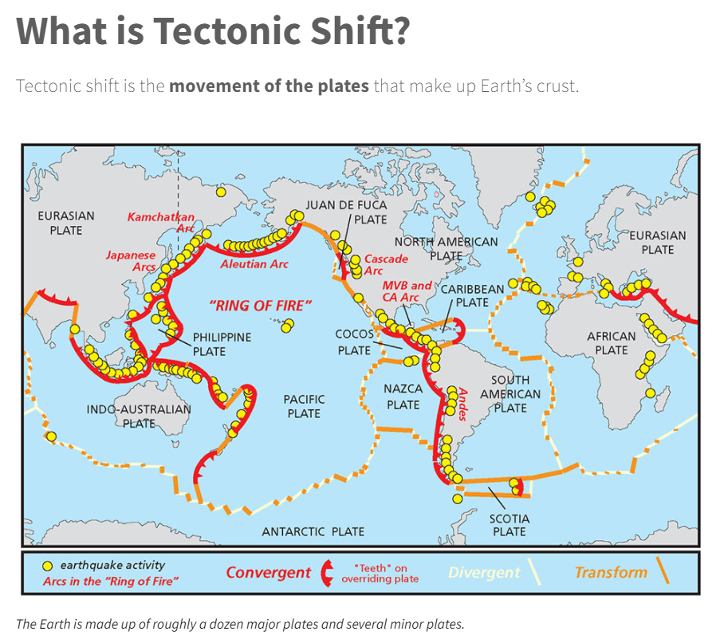
Ring of Fire
Image: National Ocean Service
The “Ring of Fire” map highlights earthquake activities around the world. As indicated in Table 5.1, earthquake or volcanic eruptions can change the shape of the geoid. Of course, they also can change the height of a mark due to crustal movement, which would typically be larger than the change in the geoid height. The amount of movement would be due to the size and magnitude of the event, but even small earthquakes could cause a change in the height of a mark located near the event. Earthquakes are occurring all over the world every day.
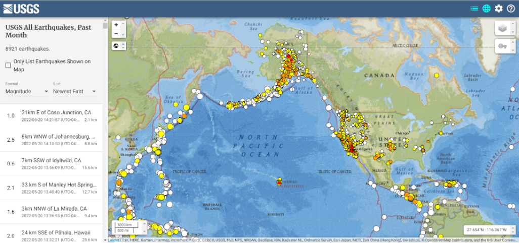
Earthquakes with large magnitudes are highlighted by news media outlets, but ones with smaller magnitude typically are not highlighted. The four figures below provide examples of earthquakes that have occurred over 30 days. This information can be obtained from the United States Geological Survey (USGS).
Earthquakes during the past 30 Days Date: May 20, 2022
Image: USGS
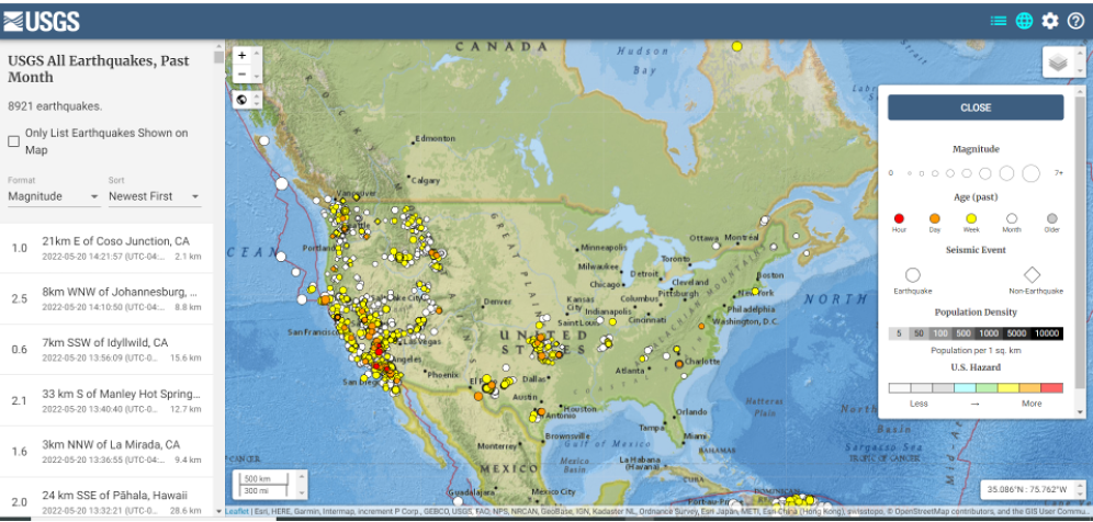
Earthquakes in the lower 48 during the past 30 days Date: May 20, 2022
Image: USGS
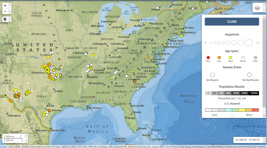
Earthquakes in eastern United States in the past 30 days Date: May 20, 2022
Image: USGS
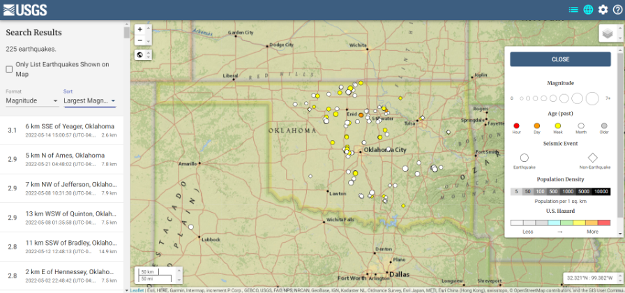
I found the large number of earthquakes that occurred in Oklahoma in just 30 days to be very interesting. This isn’t something that I thought occurred in the eastern region of the United States.
Earthquakes in Oklahoma during the past 30 days
Date: May 20, 2022
Image: USGS
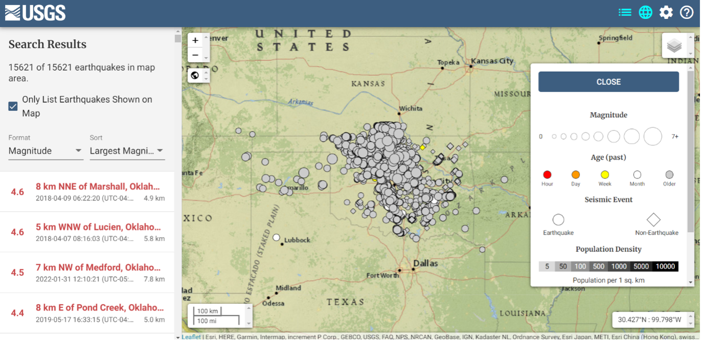
The image below depicts earthquakes that have occurred in Oklahoma in the past five years. They are fairly small in magnitude, but what is the cumulative effect on the geoid in the region, as well as changes to the orthometric heights of marks due to crustal moment in the region? This is why it is important for the new, modernized NSRS toimplement time-dependent coordinates.
Earthquakes in Oklahoma in the last 5 years Dates: 2017 to 2022
Image: USGS
To better understand the changes to the geoid, NGS performed a survey in Alaska to obtain geodetic data as part of its GeMS program. On May 12, 2022, Kevin Ahlgren, a geodesist at NGS, described in a webinar the observations collected and some of the results.
The presentation provided an overview of a field campaign performed in support of the GeMS program and a time-dependent geoid model. The campaign included static GNSS, relative gravity, and deflection of the vertical techniques on 50 stations in Alaska. The webinar was can be downloaded.
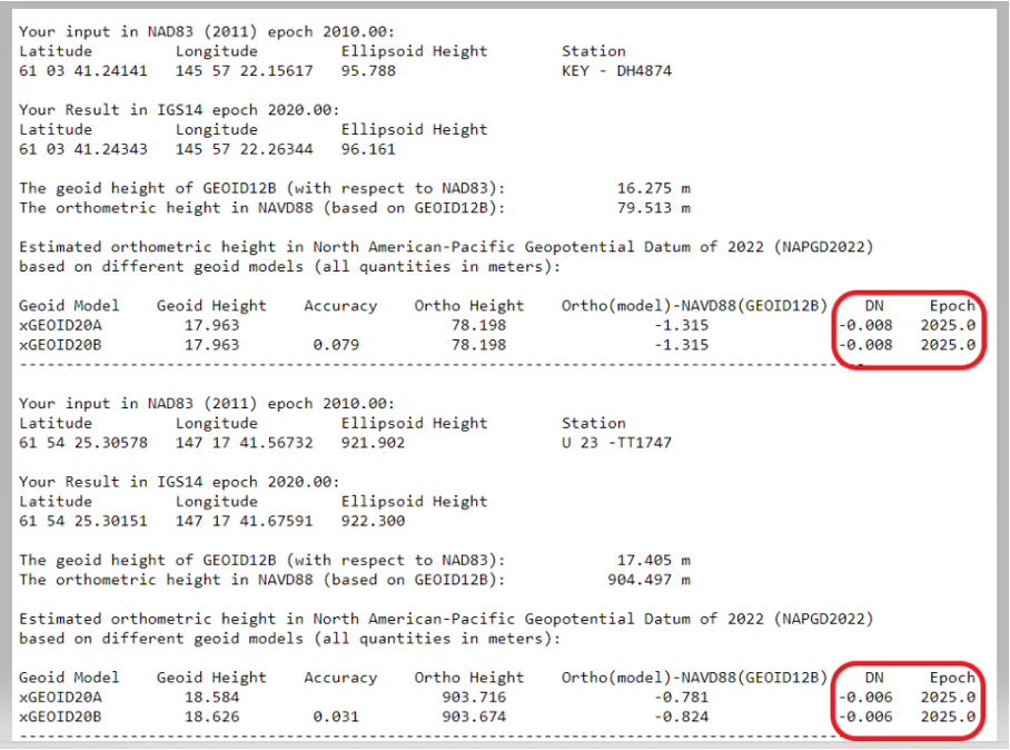
I encourage everyone to download the presentation. The change in the geoid due to geophysical drivers is small, but if the new, modernized NSRS is going to include time-dependent coordinates, then changes in the geoid must be accounted for. For demonstration purposes, NGS provides an example of the time-dependent geoid change in the xGEOID20 webtool. The box below, “xGEOID20 interactive computation output,” is an example of using this tool. The two stations are located in Alaska. As indicated in the output from the tool, the change in the geoid is 8 mm in five years. Again, NGS’s goal is to maintain geoid accuracy at the centimeter level (1 standard deviation) in both absolute and differential geoid undulations. These small changes can become significant over time.
xGEOID20 interactive computation output
Note: DN is the time-dependent geoid change computed between user inputted epoch (t) and t. (Image: NGS)
The last geoid change group that I’ll highlight has to do with the change in the gravity potential (W0) value that defines the model. The NOS NGS 64 Report states that the standing definition of the geoid, as adopted and used at NGS, is the following:
The geoid is the equipotential surface of the Earth’s gravity field which best fits, in a least squares sense, global mean sea level.
As stated in the NOS NGS 64 report, over a century of sea-level measurements imply that global mean sea level (GMSL) was rising at a rate of approximately 1.7 millimeters per year and was rising at a rate of 3.2 millimeters per year between 1993 and 2010 (IPCC, 2014). If NGS is going to define the geoid as theequipotential surface of the Earth’s gravity field that best fits, in a least squares sense, global mean sea level, then the geoid in the new, modernized NSRS must change when the GMSL exceeds a certain threshold.
Again, NGS’ goal is to maintain geoid accuracy at the centimeter level (1 standard deviation) in both absolute and differential geoid undulations. What this means is that as GMSL rises, the value of gravity potential which best fits to GMSL (called W0) will also change. In other words, the surface which was called “the geoid” and had W=W0in 2022 will no longer be the geoid. A new value of W0 (W0new) is chosen, and “the geoid” would now be the surface W=W0new.
So, what does this really mean to users? The NOS NGS 64 Report states on page 37:
“NGS and the Canadian Geodetic Survey have jointly adopted the value of 2.0 m^2/s^2 as the replacement threshold for a new geoid model (and new geopotential datum). This represents approximately 20 centimeters of GMSL (and thus geoid) rise. At the current rate of sea-level change of about +3 millimeters per year (IPCC, 2014), this means NGS expects to replace NAPGD2022 in approximately 60 to 70 years.”
Therefore, this should not be a major concern of users for a long time.
This column highlighted that orthometric heights in NAPGD2022 will be defined through ellipsoid heights and a geoid model, for instance GEOID2022; and therefore, changes in the geoid model will be very important to users estimating orthometric heights using GNSS. It briefly described the geophysical reasons for changes in the geoid that affect the orthometric height of a mark.
If NGS is going to meet the goal of maintaining geoid accuracy at 1 centimeter (1 standard deviation) in both absolute and differential geoid undulations, they will have to address changes in the geoid. The secular changes in the geoid, as indicated in Figure 13 in the NOS NGS 64 report, are very small, ranging from -1.25 mm/year to 1.5 mm/year. Once again, these are small changes to the geoid, but they will accumulate over time, and that is why NGS is including time-dependent coordinates in the new, modernized NSRS.
We all need to be careful that the numbers we are throwing around to support our case aren’t really undermining it.
Dana Goward, President, Resilient PNT Foundation
Over the last several weeks, I have repeatedly heard government officials and others talking about the value of GPS to the U.S. economy.
In each case they cited a 2019 report sponsored by the National Institute of Standards and Technology. It determined that, if GPS services were to go away, the U.S. economy would lose one billion dollars a day.
A billion dollars is a lot of money.
Yet the U.S. annual gross domestic product is more than $22 trillion a year. That’s more than $60B a day. One billion dollars is less than 1.7%.
That just doesn’t seem right.
A member of the White House’s National Security Council said “GPS is still a single point of failure” for America. That sounds like a pretty big hit to the economy. Not to mention our national security.
GPS signals are critical for networks, transportation, communications, power grid operations, first responders…virtually every critical infrastructure. If they go away, the U.S. GDP will certainly suffer much more loss than 1.7%. The economy would likely go from growing to shrinking and continue that way for quite a while.
I don’t know exactly how much the U.S. will suffer if GPS suddenly goes away, but I am sure it will be a lot. Texas alone lost an estimated $195 billion with at least 57 dead as a result of its February 2021 week-long power crisis. Although not caused by a GPS outage, the number gives us real-world benchmarks for the impacts of a major tech infrastructure failure.
If GPS fails, there will certainly be more accidents while people across the nation get used to it not being available. First responders will have a much harder time getting places and using land mobile radios. All kinds of essential services will be disrupted. More people will die than would have been the case otherwise.
In December 2021, a member of the White House’s National Security Council said “GPS is still a single point of failure” for America. That sounds like a pretty big hit to the economy. Not to mention our national security.
The authors of the NIST-sponsored study were undoubtedly diligent. But they were faced with an impossible task – to quantify the unquantifiable. And like any analysis, they were limited in what they could do by the available time, money, and hard data. They were asked for a number. They delivered one that could be easily supported.
A billion dollars is a lot of money. It might be a fairly impressive sound bite for general audiences.
Government budget analysts and policy makers, though, are accustomed to dealing with dollars in the hundreds of billions and trillions. A billion a day, while not chump change, is not a major issue.
Protecting GPS and ensuring the nation has resilient positioning, navigation and timing services are major issues.
We all need to be careful that the numbers we are throwing around to support our case aren’t really undermining it.
Dana A. Goward is president of the Resilient Navigation and Timing Foundation.
By Michael J. Dunn, Space Systems Command, Capability Area Integrator for Positioning, Navigation and Timing
The Global Positioning System is the premier positioning, navigation and timing (PNT) source for more than six billion users worldwide. It is vital to the function of all 16 of the United States’ essential critical infrastructure components. Life as we know it relies on the essential services that GPS provides.
The United States Space Force (USSF) is committed to maintaining a healthy GPS constellation that continues to deliver the “gold standard” of PNT availability and reliability throughout the world. Continuous improvements in equipment and performance have been a hallmark of the enterprise since its inception. 2021 was no exception, with a continued record-setting delivery of new capabilities.
Space Systems Command (SSC) at Los Angeles Air Force Base in El Segundo, California, is laser-focused on delivering the most important modernization in GPS history. The government and industry team are committed to bringing major upgrades to the space, control and user-equipment segments. It is an exhilarating time for the GPS enterprise. The specific updates within each segment cement the continued evolution in GPS and the USSF commitment to delivering advanced capabilities to the nation and the world.
Space Segment
Currently, 37 GPS satellites are on orbit, with 29 satellites set healthy. The baseline constellation requirement is 24 satellites. The system continues to perform in stellar fashion, providing an average 48-centimeter position accuracy throughout 2021.
Orbital systems modernization is focused on the GPS III satellite fleet, and the program continues to deliver peerless capabilities. GPS III space vehicles (SV) 1–4 were all operationally accepted in 2020. In 2021, the most notable event was the launch of GPS III SV05 in June. The satellite successfully achieved operational acceptance and mission-capable status for USSF in just under two weeks: a new record. SVs 6–8 are available for launch and are awaiting their launch windows. SV09 system-level testing is in progress. SV10 component deliveries continue. GPS III provides up to eight times better anti-jam and a new L1C signal to improve user connectivity.
For the GPS IIIF program, the long-range picture remains bright as the contract for GPS IIIF SVs 15–17 was awarded in October 2021. The delivery of the first GPS IIIF is expected early in 2026. GPS IIIF will build upon the tremendous increase in capability provided by GPS III with the addition of a search-and-rescue payload, a laser retroreflector array for precise ranging, a fully digital navigation payload, and a Regional Military Protect capability that will provide 60 times greater anti-jam for operations in electromagnetically hostile environments.
GPS III space vehicle 05 (GPS III-SV05) launched in June 2021 from Cape Canaveral Space Force Base, Florida, aboard a SpaceX Falcon 9 launch vehicle. (Photo: SpaceX)
Control Segment
The next-generation Operational Control System (OCX) continues to execute within its program baseline. OCX will provide enhanced command and control capabilities, modernized architecture, robust information assurance and cyber security.
OCX’s incremental development approach began with OCX Block 0, which is the launch and checkout system (LCS) for GPS III. The LCS successfully supported the launch and checkout of GPS III SV 01–05. OCX Blocks 1 and 2 will control all legacy GPS III satellites and both legacy and modernized signals.
Despite barriers presented by the global COVID-19 pandemic, all 17 global OCX monitoring station installations were completed in July 2021. Most of the remaining equipment was fielded throughout December 2021. System integration and verification continues with transition to operations scheduled for early 2023.
The Next Generation OCX 3F contract was awarded in April 2021. The program will modify OCX to launch and control GPS IIIF satellites with enhanced capabilities. Acquisition Milestone B is expected in 2022, and operational acceptance is planned for 2027.
MGUE: The future warfighter’s battlespace edge. (Image: Space Systems Command Production Corps)
User Equipment Segment
Millions of GPS receivers are fielded, but very few of them can use the military code (M-code) signal that is being broadcast by 24 GPS SVs. To keep our competitive advantage against the adversary, the GPS enterprise is focused on developing modernized GPS user equipment (MGUE) that takes advantage of these signals. The MGUE program is a joint service program developing modernized, M-code-capable military GPS receivers. The program is broken into two increments (Inc 1 and Inc 2). Both are designed to deliver secure PNT performance, allow navigation warfare operations, enhance anti-jam, anti-spoof and anti-tamper, and enable Blue Force Electronic Attack.
MGUE Inc 1 achieved a major milestone in September 2021 with successful testing on the Marine Corps Joint Light Tactical Vehicle (JLTV). The event took place in an electromagnetically degraded GPS environment at White Sands Missile Range, New Mexico. The JLTV is a pathfinder lead platform for the MGUE program. Lead platforms for the other services, the Army Stryker combat vehicle, Air Force B-2 bomber, and Navy Arleigh-Burke Class Guided Missile Destroyer, will commence integration testing in FY23 and FY24.
MGUE Inc 2 development continues to make progress in maturing the next generation ASIC technology required for all weapon-system platforms to provide functionality and backward compatibility. It will deliver a miniature serial interface card in CY26 to support handheld and ground applications. Eventually, MGUE receiver cards will be loaded onto hundreds of Department of Defense (DOD) weapon systems.
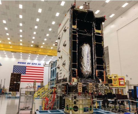
GPS III SV04 in Highbay (Photo: Lockheed Martin)
Partner Community
The GPS enterprise is committed to cooperation on a global basis. It works closely with the DOD, the armed services, the U.S. Coast Guard, other federal agencies, the International Civil Aviation Organization and all the other global and regional navigation satellite systems toward the development of PNT in the global commons.
A highlight of this cooperative work is GPS enterprise involvement in the National Executive Committee for Space-Based PNT (PNT EXCOM), which supports the interests of the various federal bodies, especially the Department of Transportation (DOT) and the Federal Aviation Administration (FAA). The PNT EXCOM is applying GPS technology to a broad variety of governmental activities, including the development of the Next Generation Air Transportation System and intelligent transportation systems.
The GPS enterprise commitment to international partners is unwavering. Our support to the North Atlantic Treaty Organization (NATO) is ongoing with support to the Capability Panel 2 for Navigation working toward the integration of MGUE and compatibility arrangements with Europe’s Galileo system. A highlight this year was the first delivery of MGUE loan equipment to the United Kingdom, Canada, Germany, and the Republic of Korea. Germany is the first country to purchase MGUE equipment.
Conclusion
GPS is the foundation of global PNT and a cornerstone of modern life. Improvements to the enterprise are continual. As the nation moves into the complex and dynamic world of the coming decades, the dedicated military, civilian and industry professionals that provide this world-changing capability will continue their challenging and rewarding work. Semper Supra!
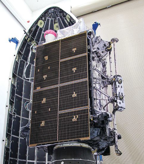
The “encapsulation” of a GPS satellite. (Photo: U.S. Department of Defense)
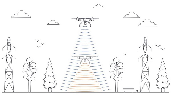
This image shows the effect of increased elevation on surface area and obstacle avoidance. (Image: Advanced Navigation)
By Simon Harris, Advanced Navigation
Lidar-based surveying is increasing in demand across a range of industries. Recent market analyses indicate that lidar surveying is a multi-billion dollar industry that is expected to deliver sustained growth for years to come. As lidar technology matures and performance increases, its range of use is broadening into surveying more complex and difficult terrain or at speeds and in environments previously unsuited to such technology. Naturally, increasing diversity and performance brings about demands for greater reliability, speed and accuracy whilst remaining within physical and regulatory limitations.
Keeping pace with market demands in UAV and rail sector lidar surveying is increasingly challenging and requires an evolving synthesis between the acquisition and processing of lidar and GNSS-INS georeferencing data. Companies such as Cordel and its subsidiary Nextcore are taking advantage of the latest technologies to develop systems that are setting new benchmarks in these sectors.
Benefits of Altitude, Faster Lidar and Precision INS
UAV lidar surveying is capable of high-resolution surveys of complex terrain, vegetated areas and in light conditions that may be unsuitable to photogrammetry. These qualities make it a preferred option in many applications. However, it must remain cost-competitive with alternative solutions to become widely adopted by the surveying industry.
Typical UAV lidar surveying is performed at ~40m AGL. This altitude commonly presents collision risks with terrain and vegetation and imposes limits where the topography changes dramatically, such as voids that increase AGL beyond acceptable limits. Higher altitude surveying, therefore, offers obvious advantages, but also deeply challenges lidar sensors and the INS. Any mismatch in operational performance and accuracy between these inevitably degrades survey quality and severely limits use of the system.
Nextcore accepted the challenge and set about developing a viable solution that could maintain a point cloud density of 200-500 points per m2 from a target altitude of 70 m. This equates to generating lidar point cloud data at millions of points per second. Achieving this required a GNSS-INS that provided suitably precise georeferencing data. Because survey data is derived from a source that is in constant motion in 3D space, the capability of the GNSS-INS is paramount in producing a digital twin of value and is critical to mission success.
After testing and evaluating various INSs from different manufacturers, Nextcore coupled its lidar with Advanced Navigation’s MEMs-based Certus Evo INS, which provides near-FOG performance and has a drift rate of 0.2 degrees/hour. This combination yielded exceptional results that allowed them to vastly extend the altitude ceiling to 120m while retaining consistent, accurate survey data.
“Operation at this altitude not only reduces the risk of collisions with trees, it enables surveyors to cover larger areas, greatly improving the solution’s efficiency,” said Ashley Cox, founder and COO of Nextcore.
Higher altitudes tend to increase the lidar swath width. The typical swath width at ~50m altitude is ~120m, depending on actual altitude and the resulting angle of incidence of lidar toward the edges of the swath. At 120m, a reliable swath width of 180m was achieved. This is a 50% increase over previous, equating to approximately 33% fewer flight-lines to survey a given area — a notable boost for productivity and efficiency to surveyors.
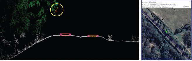
Example of rail track lidar showing encroaching vegetation, with associated map and location information. The yellow circle in the lidar data shows vegetation that is starting to intrude into the train’s path. (Images: Advanced Navigation)
Payload minimization also was a critical aspect in the search for an INS, as surveyors are always seeking longer flying time. This only can be achieved with a lighter technology stack payload. The team used an OEM version of the INS for a smaller form factor that could be integrated within a single ruggedized housing. This allows a design with greater strength, weather resistance and efficient payload setup.
“The industry is constantly seeking lighter payloads for longer flight times and to fit on smaller, safer UAVs,” Cox said. “Regulatory restrictions challenge the industry to meet certain specifications. The same is true for UAV lidar. We hit a ceiling. We need to be able to improve on that, although what we’re achieving now is a real game changer.”
The resulting survey material contains lidar point cloud data and the geo-referencing data from the INS. All data processing is performed post-flight to ensure the highest possible accuracy. PPK is used for correction of GNSS-INS position, roll, pitch and heading data. The processed INS data is then combined with the processed point cloud data to provide absolute position to the point cloud. This system realized consistent 30~40mm precision at 120m AGL. Nextcore has integrated the lidar and INS processing platforms to automate the synthesis of data sets, reducing the survey completion time. Depending on the survey’s size and complexity, this solution can process survey data into a 3D map within 30 minutes of mission completion.
Nextcore used a Certus Evo GNSS receiver, which internally uses the u-blox ZED-F9P chip. It logs GPS L1, L2, GLONASS L1, L2, Galileo GalE1, E5, and BeiDou B1, B2 frequencies at 8 Hz. It used the Kinematica correction service running a PPK filter.
Lidar sensors have become light enough to mount on UAVs (Photo: Advanced Navigation)
Scanning Rail Corridors Super Fast
Aerial surveying is not the only environment to present challenges to lidar and INS.
Train-mounted lidar for automated track and rail corridor surveying is another burgeoning market. This application typically uses lidar and position data to detect and identify areas of the railway that require maintenance and, perhaps more importantly, preventive maintenance. Rail surveying presents unique demands, including operating at speeds of 160km/h (100mp/h) or more, maintaining position accuracy during GNSS outages and variable environmental conditions.
Land-based surveying provides flexibility for selecting an INS compared to aerial applications, as size and weight are usually irrelevant. Rail surveying also requires an INS that provides the necessary performance while tolerating vibration and erratic movement from junctions, points and signals, and be absolutely dependable in GNSS-denied situations. Cox’s team found that the greater accuracy and better drift stability of FOG INS over MEMS provided an ideal platform for generating reliable and accurate paths of train trajectory.
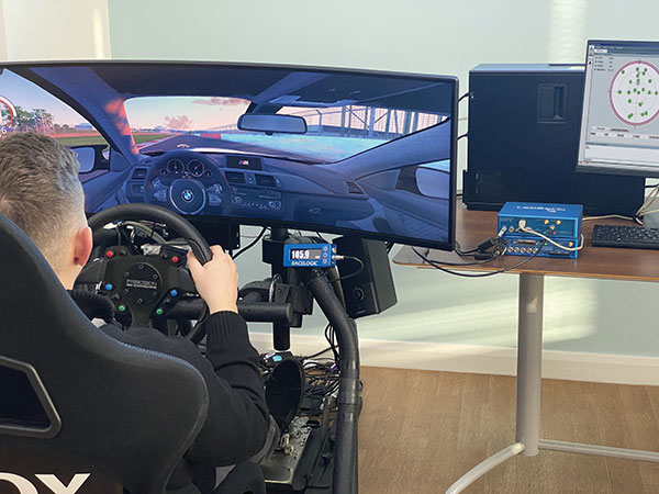
Cordel tested Advanced Navigation’s Boreas digital FOG INS as a potential solution. Testing was carried out using cars as a simulation, travelling complex routes in two directions then overlaying the lidar point clouds to check for discrepancies or unsynchronized areas. The results provided the confidence to put the Boreas into service.
Railways typically traverse deep cuttings, lengthy tunnels and other environments that disrupt GNSS. It is mission-critical that the INS can apply dead reckoning the instant GNSS is disrupted and maintain accurate position for the entirety of the outage. Reliable path and location data during GNSS disruptions is central to the viability of automated rail surveying. Blind spots or zones of unreliable route data cannot be tolerated by rail operators from safety, track availability and financial perspectives.
The Cordel AI lidar analysis system can be “tuned” to the required metrics and is capable of self-learning. The AI enables the system to pre-emptively identify and flag areas of concern before they become an actual problem or hazard. Examples include measuring track gauge and alignment, ballast distribution and coverage, and clearance between potential hazards to the train. The entire route is logged, creating a “Google map” of the railway that maintains a historical record of survey data each time the track is used.
Clients can then view a representation of the lidar data to get a clear understanding of any issues and how to respond before sending personnel or assets to a location. This enables intervention before safety is compromised or remedial works become large-scale and disruptive. As a result, rail service providers can maintain safer railways, deliver more reliable services, and minimize operating costs.
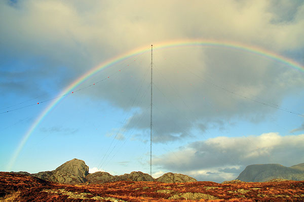
the former Loran-C transmission antenna at Værlandet, Norway. (Photo: UrsaNav)
By Alan Grant and Dana Goward
In my “First Fix” editorial in the January 2022 issue of this magazine, I listed 10 questions about eLoran I had received from a PNT expert in response to an article about eLoran I wrote for the November 2022 issue. I encouraged eLoran proponents to address these questions. Two well-known authorities, neither of whom have a financial interest in the technology, stepped forward to help. Below, again, are my 10 questions about eLoran and their answers.
Alan Grant is head of Research and Development for the General Lighthouse Authorities of the United Kingdom and Ireland (GLA). He is an expert in radionavigation systems and leads the team that established the U.K.’s eLoran system, which operated from 2007 to December 31, 2015 in support of maritime users.
Dana A. Goward is president of the Resilient Navigation and Timing Foundation and a retired U.S. Coast Guard Captain. He also served in the federal Senior Executive Service as the maritime navigation authority for the United States. He has decades of experience with navigation policy and leading government policy and programs.
— Matteo Luccio, Editor-in-Chief
Accuracy specifics. While my November article stated that eLoran would have a two-dimensional accuracy of “better than 20 meters, and in many cases, better than 10 meters,” is that RMS, 95%, or some other statistic?
AG: Like any radionavigation system, the achievable accuracy will depend on several aspects, including the user’s location with respect to the broadcast stations and how error sources are modelled. The GLA eLoran service, when in operation in 2015, provided positional accuracy in the order of 8-10m (95%) to seven ports on the east coast of the UK. These ports had local reference stations to help manage temporal errors and the ports had been mapped to correct for additional secondary factors (ASF).i
DG: Others have reported greater accuracies using differential corrections.
Performance standard. GPS provides a commitment to users in a published performance standard. What specific measures of positioning accuracy, integrity and continuity would you recommend the proposed eLoran system be committed to provide (using the architecture described in the answer to Question 6)?
AG: The target performance would need to be tied to the target use cases to ensure the appropriate requirements are met. IALA provides guidance in this area for maritime services with general maritime requirements provided by the IMO within resolutions A.1046 and A.915.
Coverage. Would you recommend this eLoran positioning performance hold for the entire United States (including Alaska, Hawaii, Puerto Rico and other territories), only for the “lower 48” states, or only parts of these 48 states?
DG: The primary goal of any effort to complement and back up GPS/GNSS would be to make the nation and its citizens safer in at least two ways. First, to provide an alternative PNT source or sources in the event that signals from space were not available for any reason. Second to make GPS satellites and signals (and therefore the nation) safer by “taking the bullseye off GPS.” Having one or more alternatives will greatly reduce incentives for malicious disruption. To achieve these two goals the alternatives must be widely available and easily accessed. How widely available and easily accessed the United States or any other country wants to make such systems is a policy decision.
Current users. By number of users, the predominant common current civil uses of GNSS for positioning are consumer devices (mostly cellphones). By contribution to the U.S. economy, the predominant uses are high-precision applications. For what fraction of these uses would eLoran positioning be adequate? Could an eLoran receiver and antenna fit in today’s consumer devices?
DG: Lots of presumptions and assumptions in this question. Several overall thoughts, though. First, determining users’ real requirements can sometimes be difficult. I have a nice new full-size sedan. So, I think that is my requirement even though I could get to work almost as quickly and much less expensively if I owned a used compact car or caught the bus at the corner.
Second, GPS/GNSS will, hopefully, always be the primary source. The questions then are 1) how accurate can eLoran positioning become with additional work, and 2) how accurate does a fallback system need to be?
Durk van Willigen of Reelelektronika b.v. displays a combined GPS, GLONASS and eLoran receiver at the 2017 Munich Satellite Navigation Summit. (Photo: Reelelektronika)
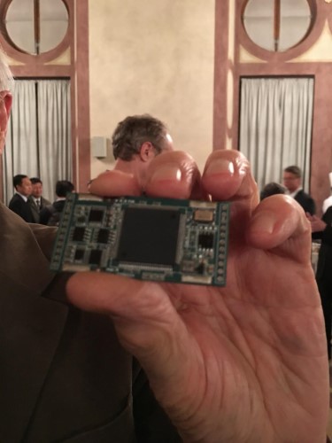
Finally, as to equipment size, I recall seeing a photo of the first GPS receiver sitting on a pallet with two chairs for operators. Today, receivers are made at chip scale. Huge reductions in C-SWAP have been the growth arc for all kinds of technologies as they are implemented more and more widely.
In 2017 the Dutch company Reelektronika showcased a combination eLoran, Chayka, GNSS receiver that was only 6 cm long. This was achieved without a whole lot of investment in research and development. Who knows how low C-SWAP for eLoran receivers will go?
Future uses. Emerging civil uses of GPS for positioning include autonomous ground and air vehicles, navigation to space and in space, and lane-accurate car navigation. Which of these could be served by eLoran?
AG: The overall concept of having a mix of dissimilar position sources remains sensible for all modes. GNSS is expected to remain the primary means of position determination, with different use cases selecting different complementary systems based on their needs. eLoran may support some use cases but may not be the answer for all.
DG: Many believe GPS alone is not sufficient to serve some of the applications cited. This is the basis for language in both the European Radionavigation Plan and a U.S. Presidential Executive Order cautioning against over-reliance on GNSS. Perhaps GPS and eLoran together might be deemed sufficient. Or, perhaps a more diverse and resilient PNT architecture will give rise to additional applications such as precise positioning from 5G that will be sufficient.
Architecture. To maintain accuracy during a prolonged GPS outage, eLoran would require reference stations to calibrate time-varying propagation errors, as well as a certain number of transmitters for good nationwide geometry and for redundancy, ensuring service even if a transmitter is attacked or is taken off-line for maintenance. What architecture would you recommend to achieve this?
AG: The MarRINav projectconsidered a similar question for the UK and the project’s approach could be employed to consider this question for the United States.iv
DG: A good starting point for the United States might be the sites used by the shuttered Loran-C system. The federal government still retains custody of most of them. Also, considerable thought has been given to the questions of eLoran reference stations and integrity in the United States. PNT expert Mitch Narins, formerly of the FAA and now Strategic Synergies, advises that much of this work has been done. The FAA and Coast Guard conducted a study to deploy eLoran in the United States to support aviation non-precision approach, maritime harbor entrance and approach, and precise time and frequency users. The proposed architecture supported aviation’s demanding integrity requirement (1×10⁻⁷), maritime’s demanding accuracy requirement (8-20m), and time and frequency users’ precision requirements (100 ns/Stratum 1).
7. Infrastructure cost. What would be the cost of installing the required transmitters, power supplies, reference stations, communication links and control system for the architecture described in the answer to Question 6? Can you reference a recent and independent estimate? To a ballpark figure, what cost fixed-price contract would you accept to implement it? Similarly, what would be the annual costs for operating and maintaining this infrastructure?
AG: The MarRINav project produced a cost-benefit analysis report that addresses some of these questions, albeit aligned to the approach proposed for the UK. The documents are open source and available on the MarRINav website.
DG: To quote President Kennedy, “There are costs and risks to a program of action, but they are far less than the long-range risks and costs of comfortable inaction.”I agree with Dr. Grant that the capital costs in MarRINav are roughly transferrable to the United States. As another data point, the 2010 operating cost for Loran-C in the United States was about $36M/year. That number included several hundred employees, though. Plans to automate the system projected reducing annual costs to $15M/year in 2010 dollars.
Impact. eLoran transmitters are large and high-power. Providing positioning across the United States could require building some of them from scratch or significantly reconstructing old Loran sites. What issues — such as environmental, aviation safety and security — would this raise, and how would you recommend they be addressed?
DG: These issues would be dealt with the same way they are for any construction project. eLoran transmission sites are essentially the same as commercial AM radio stations. Reusing sites still owned by the government could make the process even easier. Compared to the cost and difficulty of putting PNT assets in orbit, these challenges should be relatively easy to overcome.
Receivers. Assuming all the above were achieved, it would accomplish nothing unless eLoran receivers were widely purchased, installed and used. How much would that cost? Who would pay? Should we assume that “if we build it, they will come”?
AG: This is a valid concern and has different answers depending on the planned use case and the level of national/international standardization required. Within the maritime sector, the IMO has approved a multi-system receiver performance standard that supports the use of all GNSS and terrestrial systems within one device, rather than having a separate eLoran receiver.
DG: I completely agree — adoption and use are absolutely key. Fortunately, government leaders have a wide variety of levers to influence adoption and use. These range from education and encouragement to regulation, legislation, and subsidies.
Alternatives. Given the widespread development of other positioning technologies over the past decade, much has changed since the earlier recommendations for eLoran. How do we know that eLoran is the right investment — or even a needed part of the solution or needed system in a system of systems — for the future of U.S. PNT?
AG: The MarRINav project researched and compiled details of different positioning, navigation and timing technologies supporting maritime navigation, within Deliverable D4. The recommended system-of-systems approach recognized that there was no one-fit-all solution, rather it sought to allow for a scalable solution that reflects users moving from location to location and between systems. It considered global, regional and local solutions, recognizing the cost vs. usable coverage tradeoff for each. The proposed solution of GNSS, supported by eLoran in combination with VDES R-Mode and radar absolute positioning, was deemed as the most appropriate mix for the UK, given geographical and political constraints. The approach can be ported to investigate the appropriate options for the United States.
DG: The U.S. Department of Transportation’s January 2021 report to Congress has findings similar to those in MarRINav. It described a system of systems that included fiber, satellites and terrestrial broadcast. The department subsequently said that a critical factor for a terrestrial broadcast system would be the coverage area per unit of required infrastructure. Of the systems discussed, eLoran met this criterion best. This recent finding is consistent with numerous other government reports, two previous government announcements that it would build eLoran, two recommendations from the President’s National Space-based Positioning, Navigation, and Timing Advisory Board and the technology’s on-going use around the world. Likely someday there will be something to replace GPS and other legacy technologies. We must work with the combination of technologies we have now until that day arrives.
Common Threats
Common threats to GNSS and eLoran could include the following:
1. Cyber attacks. Given that GPS’s OCX is said to be the most cybersecure system built by the U.S. Department of Defense, how would eLoran’s control system be even more cybersecure than OCX, to avoid a common cyber-vulnerability?
AG: Cybersecurity is a key concern and one that any navigation and safety of life system must consider. I will leave manufacturers of each system to comment on how secure they are. However, if we consider signal interference and data manipulation within this category, then using a stronger signal at a different frequency to GNSS provides some protection against jamming. While any radio signal can be jammed, the perpetrator would need more power and physically larger equipment to jam at lower frequencies.
DG: Yes, the security of control systems is very important and must be included in the design up front. Authentication and security of signals, and the cybersecurity of receivers must be as well. This is especially true for complementary systems for GPS since GPS signals are so open and vulnerable, and so many receivers are largely unprotected. We will have the opportunity to do better with a new system and avoid the huge expenses of OCX, the new GPS control system.
Additionally, let us not forget that cybersecurity is needed for much more than control systems. Signals and receivers need to be much more secure than civil GPS is right now. A new system, be it eLoran or another technology, will be able to build cybersecurity in from the beginning.
Physical attacks. Given concerns about possible physical attacks on GPS satellites, which move at multiple km/sec 20,000 km from Earth, would it not be easier to physically attack eLoran transmitters, which are stationary, terrestrial, in remote locations, and hundreds of feet tall and require massive power sources?
AG: We should not lose sight that any ground infrastructure can be attacked, regardless of whether it is a satellite uplink station or part of a terrestrial communications or positioning system. Careful selection of the transmitter location, along with suitable site security options should help deter the attack and mitigate the impact where possible.
DG: Every physical asset and every signal is vulnerable to some degree to attack by a host of malicious actors, and damage by a variety of natural occurrences. The key to resilience and making PNT sources less attractive targets is to have diverse sources with the smallest number of common failure modes.
Space weather. GPS is potentially vulnerable to severe space weather that could damage satellites or temporarily hinder signal propagation from space to Earth. However, severe space weather could also damage the power grid upon which megawatt eLoran transmitters rely. How would eLoran service be protected from the effects of severe space weather, such as a Carrington Event?
AG: Space weather has the potential to affect all radio broadcasts. Depending on the type of event it can affect performance several different ways, including ionospheric scintillation, applying forces to satellites or disrupting power networks. The aim is to use systems where the underlying failure modes are as different as possible. Using a combination of satellite and terrestrial signals, at different frequencies, with local power generation where possible can help mitigate the impact. Whether it’s possible to mitigate all the implications of a Carrington type event is not clear and perhaps one for the experts.
DG: With the available warnings about solar events, it is conceivable that both GNSS and terrestrial systems could be powered off or otherwise secured for such an event to minimize damage. A new-build terrestrial system could also be constructed with surviving a Carrington Event in mind. And, of course, terrestrial systems will be easier to access, repair, and replace than those in space. As for other possible issues with the power grid, generators, uninterruptable power supplies, and other backup methods can easily be installed. Before 2010, several U.S. Loran-C transmitters were in such remote locations, they never had grid power and were always powered by generators.
On March 24, the U.S. Department of Energy (DOE) released information about a program designed to provide resilient timing to the electrical grid by fiber.
More than just an academic center for research, CAST is building a network of atomic master clocks and methods of time delivery by fiber that will ensure power grids always have failsafe and resilient time.
Timing is essential to a wide variety of equipment and network functions essential to electrical grids. Most of these use time signals that come directly from, or can be traced back to, signals from GPS.
Electrical-grid timing dependent equipment and networks
Transmission-line fault detection
Frequency measurement
Synchrophasors/phasor measurement units
Internet-based market transactions
Substation control/resynchronization
Disturbance monitoring event recorders
Protective relays
Bulk metering
SCADA networks
Synchrophasor networks
An industry expert once observed, “Electrical grids won’t fail without accurate time signals, but they are impossible to manage. And who wants an unmanageable grid?”
According to David Wells, program leader for CAST at DOE headquarters, “It has been no secret there are vulnerabilities within the timing and synchronizations platforms used by the energy sector.” Wells said that for grid timing “a secure, verifiable, and reliable solution is paramount.”
He sees CAST as a necessary part of tech evolution for electrical grids and service. “The sector has been going through a transition from analog to digital and then from digital to internet protocol (IP). Technologies have been bolted on, but with each bolt-on added, access vulnerabilities are added as well. Embedded stratum timing systems based through digital carriers allowed our networks to be closed-loop (zero-trust) for 50 years. During the age of IP conversion, the ability to provide timing via stratum was lost, so the sector moved to GPS and NTP, which provided precision at the locations, but lack security, validation and true wide-area synchronization.”
CAST’s goal is to establish “true closed-loop (zero-trust) with secure bi-direction timing validation and synchronization over IP networks,” with multiple clocking sources, according to Wells. The system, he said, will be able to reach all power substations and remote locations.
While Wells, his office and ORNL are the primary players, a whole cast of other organizations contributes to the effort. These include DOE’s Office of Electricity; its Office of Cybersecurity, Energy Security and Emergency Response; Savannah River National Laboratory; Sandia National Laboratory; and industry partners.
CAST will not be creating new infrastructure, but rather leveraging fiber already in place. “This is not a dedicated fiber network for timing,” said Wells. “CAST uses existing fiber in the form of dark fiber (underutilized fiber), commercial fiber and optical ground wire, and works with wireless technologies to extend secure timing and synchronization to users.”
While CAST is narrowly focused on electrical grids and fiber, some see a potential for it to be the basis of a wider national security effort.
Marc Weiss is a timing expert and consultant who served for more than 40 years as a theoretical physicist for the National Institute of Standards and Technology. “CAST could be part of the foundation of an architecture that benefits all sectors and citizens, not just power grids,” he said. “The Department of Transportation has identified the need for Americans to have access to timing signals from space, from terrestrial wireless transmitters, and via fiber to have the kind of resilience they need. So, CAST is certainly a big step in the right direction.”
DOE’s DarkNet initiative is a joint initiative by the Office of Electricity and the Office of Cybersecurity, Energy Security, and Emergency Response (CESER). Additional information on DarkNet and CAST can be found at https://darknet.ornl.gov
Lidar sensors that used to cost tens of thousands of dollars now cost only hundreds of dollars. With prices significantly decreasing, 3D sensors are more accessible than ever before. Now, what was once a niche technology exclusively for autonomous vehicles is being deployed globally to make places safer and smarter. Additionally, the industry is continuing to grow: market analysis firm Yolé estimates that the lidar industry will be worth nearly $4 billion by 2025, a 19% CAGR between 2020 and 2025.
While decreasing sensor prices are a critical factor in the proliferation of lidar, an arguably more significant development is the development of robust perception software that can track, identify and monitor with far greater accuracy and efficiency than ever before.
Effective 3D sensors, from lidar to radar and 3D cameras, require both hardware and software components. The hardware is critical to capturing data with high resolution and accuracy, while the software processes and comprehends the data, making them actionable. Essentially, software is the “brain” of sensors. Lidar, without equally strong perception software, is like an iPhone without iOS — inoperable and just a piece of machinery.
Today, at the confluence of these factors, we are beginning to see a proliferation of 3D perception applications beyond autonomous driving. Cities, security and retail are a few key sectors where I predict we will continue to see advancements over the next few years.
Making Cities Smarter
The steep drop in the cost of lidar sensors has made 3D sensors more accessible than ever. (Image: Seoul Robotics)
Today’s cities have a variety of challenges to address, from decreasing traffic collisions to reducing congestion, and we are witnessing municipalities leveraging lidar to collect critical insights into city safety and efficiency.
However, why are they turning to 3D solutions, specifically? Because they can capture the data necessary to make actionable changes. 3D sensors were developed to quickly track and analyze city surroundings for autonomous vehicles, so they are an effective way to ensure that vehicles are not veering into opposing lanes or traversing crosswalks already occupied by pedestrians.
Cities also adopt 3D applications because they can often address multiple challenges with one system. For example, a city may install a lidar system on an intersection to detect traffic violations, but the system can also capture data about pedestrian safety and traffic flow. These multi-benefit solutions are ultimately more cost-effective for cities because they eliminate the need to install multiple different solutions to solve these problems.
Creating Safer Spaces
Companies are turning to 3D data to create safer and more secure environments. (Image: Seoul Robotics)
From airports to museums, from stadiums to music venues, the market for 3D-based security solutions is vast. While each of these environments is unique in how it operates, they all rely on technology to ensure that areas are secure, visitors do not enter prohibited areas, and crowds are seamlessly moving through the space.
3D perception helps address these challenges by creating “zones” that can alert security systems if someone enters. Additionally, because 3D sensors can detect and track various objects, including humans, they are increasingly becoming a popular solution for crowd control. They can help venues monitor and address foot traffic, such as with security lines, and they can be valuable in the event of an emergency to ensure that an area is clear.
Beyond the tangible benefits 3D sensors bring to different venues, companies are turning to 3D data to create safer and more secure environments because they are more accurate and anonymous. Unlike traditional camera-based systems such as CCTV, which are often prone to false positives, 3D data are incredibly accurate and precise, so they are less likely to set off alarms unnecessarily. Additionally, 3D data do not include biometric information, so they address privacy concerns while still ensuring that areas are secure.
Building 3D Retail Environments
By implementing 3D-based solutions into a physical retail environment, companies can better understand how shoppers are moving through and spending their time in stores. They can glean insights into key metrics, such as:
How long are people in line?
What areas of the store are receiving the most traffic?
With what products are people engaging most frequently?
As one example, Mercedes-Benz has integrated 3D sensors into its showrooms in Korea, gaining fascinating insights into customer behavior. For example, they’ve discovered that nearly 60% of customers spend their time looking at the trunk space of SUVs, and that red is the most popular color.
As these solutions continue to become more sophisticated and accessible, we should expect to see them in more areas of our everyday lives. The future of 3D perception is exciting, and it will ensure safer, smarter and more efficient spaces — improving the quality of life.
HanBin Lee is CEO of Seoul Robotics, a 3D perception company specializing in lidar.
ByBradford W. Parkinson Aeronautics and Astronautics Professor Emeritus (recalled) Stanford University
Brad Parkinson
We, of the PNT universe, have been hearing a rather continual message of doom from the media regarding the fragility of the GPS (or GNSS) signals. In a way, they are right. The received GPS signal is 1/10th of 1 millionth of 1 billionth of a Watt. It can be susceptible to jamming and spoofing.
In response, the U.S. government has sponsored major studies and some competitive tests of techniques to augment or possibly replace GPS. I applaud such queries, but also would strongly advocate more balance in efforts to increase robustness of positioning, navigation and timing (PNT).
Specifically, I argue for increased emphasis on well-known techniques that can greatly toughen GNSS receivers to both jamming and spoofing. Some of these techniques are deliberately denied to civil users by government policy.
Background
The PNT Advisory Board (PNTAB) is a panel of national experts who report to the PNT ExCom. The ExCom is comprised of the deputy heads of the nine U.S. government departments with the largest stakes in PNT. The PNTAB has a starkly simple and well-stated goal:
To meet its overarching goal, the PNTAB has developed a three-legged strategic framework, known as “PTA”: “We must protect, toughen and augment GPS to ensure that it continues to provide economic and societal benefits to the nation.”
Most current U.S. government efforts have been focused on the third of the PNTAB strategic legs: augmenting the GPS system. These system augmentations include: modernized Loran (eLoran), fiber-optic distribution of time, and ranging to low-Earth-orbit (LEO) satellites (particularly the swarms of communications satellites). In general, these system augmentations offer no hope of being equivalent to GPS in terms of availability and accuracy.
However, augmentations have the advantage of either being less vulnerable to interference, or highly proliferated in case of satellite outages. As supplements, or in an emergency, they can perform a very valuable role, but with nowhere near the equivalent performance of normally operating GNSS, which can routinely provide worldwide, 24/7 precisions better than decimeters in the dynamic real-time kinematic (RTK) mode. In the United States, GPS also offers continuous, real-time integrity assessments courtesy of the FAA1. Europe has a similar, compatible integrity system called EGNOS, and there are other regional system augmentations.
In summary, the current PNTAB assessment regarding these substitutes is:
“No current or foreseeable alternative to GNSS (primarily GPS) can deliver the equivalent accuracy (static down to millimeters) and worldwide, 24/7 availability.”
Toughening User Equipment
Toughening, the second leg of our assurance strategy, includes all aspects of GPS enterprise vulnerability — satellites, ground control and user equipment. For this article, I am focused on toughening the user equipment. I would argue that we have largely under-emphasized, or been prohibited by national policy from using, well-known and widely available user equipment toughening technology.
The main vulnerabilities of GPS receivers are jamming and spoofing of the received signals. Familiar anti-jam (A/J) methods can substantially overcome the inherent weakness of GPS signals to defeat deliberate jamming and spoofing. As I outline here, such measures can reduce a jammer’s effective radius by a factor of more than 100 and reduce the effective jammer area by a factor of 10,000 compared to the unprotected receiver.2
Thus, these methods are also deterrents, because they can render ineffective such hostile (or possibly inadvertent) acts. Further, the technology that provides this significant toughening is available now or will be within a few years, rather than the many years required by some alternative, system-level augmentations.
Toughening techniques (A/J improvements) are traditionally calibrated as the improvement in the amount of jamming that can be tolerated, measured by the jamming-to-signal power ratio (J/S) expressed as decibels (dB). However, for this discussion, I will also use a different, more intuitive, measure. This metric is the Denial Radius Reduction Ratio (DRRR):
DRRR = (radius of jammer denial after J/S measure applied)/(jammer radius without improvements)
For example, a 15-dB improvement in J/S would lead to a DRRR of 0.178.3 In other words, the 15-dB improvement has reduced the denial radius to about 18% of the line-of-sight radius that would be denied to an untoughened receiver. Note that the simultaneous use of techniques is generally multiplicative. For example, simultaneously applying technique #1 with a DRRR1 of 0.5 and technique #2 with a DRRR2 of 0.3, would result in a DRRR1&2 of 0.3 *0.5, or an overall DRRR of 0.15. This is the advantage of using this metric to describe the A/J improvements. 4
Baseline Case
For our basis for comparison, we will consider the L1 C/A signal in full accuracy (State 5) tracking mode and a 1-kW noise jammer.5,6 For this situation, the line-of-sight jammer could deny GPS to a radius of about 560 kilometers. A discussion of the lower accuracy State 3 tracking is included below.
It is useful to consider toughening techniques in four major categories.
Toughening Category 1: Signal Processing. With L1 C/A, GPS receivers can improve jamming resistance, albeit with loss of ranging (tracking) accuracy, by using code tracking mode – State 3. This reduces a line-of-sight jammer’s denial radius (DRRR) to about 0.29 (a 10.7 dB improvement).
Toughening Category 2: Inertial Components and Very Stable User Clocks. This includes miniature micro-electromechanical (MEMS) components up to high-grade inertial measurement units (IMUs) and quartz to chip-scale atomic clocks (CSACs). These techniques enable narrower tracking filters and longer averaging, as well as allowing navigation through regions when GPS is denied. The range of DRRRs is 0.40 down to 0.10. We will use a nominal value of 0.18 (a 15-dB improvement).
Toughening Category 3: CRPAs. Controlled reception pattern antennas (CRPAS) are digital, multi-element, phase-steered antennas. They represent well-understood and available technology; they have been used in large surface-search radar systems for many decades.7 They can be used in null-steering or beam-steering modes.8 The number of antenna elements could range up to dozens. Potentially, they could produce DRRRs down to .01 — that is, a 99% reduction of jammer radius to 1% of the unprotected GPS receiver value.
Unfortunately, the U.S. government does not allow more than three-element CRPAs to be manufactured or sold for civil use. 9 This is due to some very old International Traffic in Arms Regulations (ITAR). For our nominal example, we will assume the restriction has been relaxed and use a CRPA of about 20 elements, which should produce a DRRR of 0.06 (a 25-dB improvement).
Toughening Category 4: Signal Alternatives. This category includes alternative modulations at 1575 MHz (L1C, Galileo or other GNSS) and alternative frequencies (L5, L2, Galileo). Note that the modern signals generally offer significantly improved signal-processing toughening as well as increased power.
Using L1C in State 3 compared to L1 C/A in State 5 would yield a DRRR of 0.10. (a 20.3-dB improvement). The L1C international signal should be operational on GPS by mid-decade. The L5 signal, at 1176 MHz, is clearly the most capable of the civil GPS signals in terms of jam resistance. L5 also should be declared operational by mid-decade. As the use of LEO communication satellites matures, their use may also fit this category.
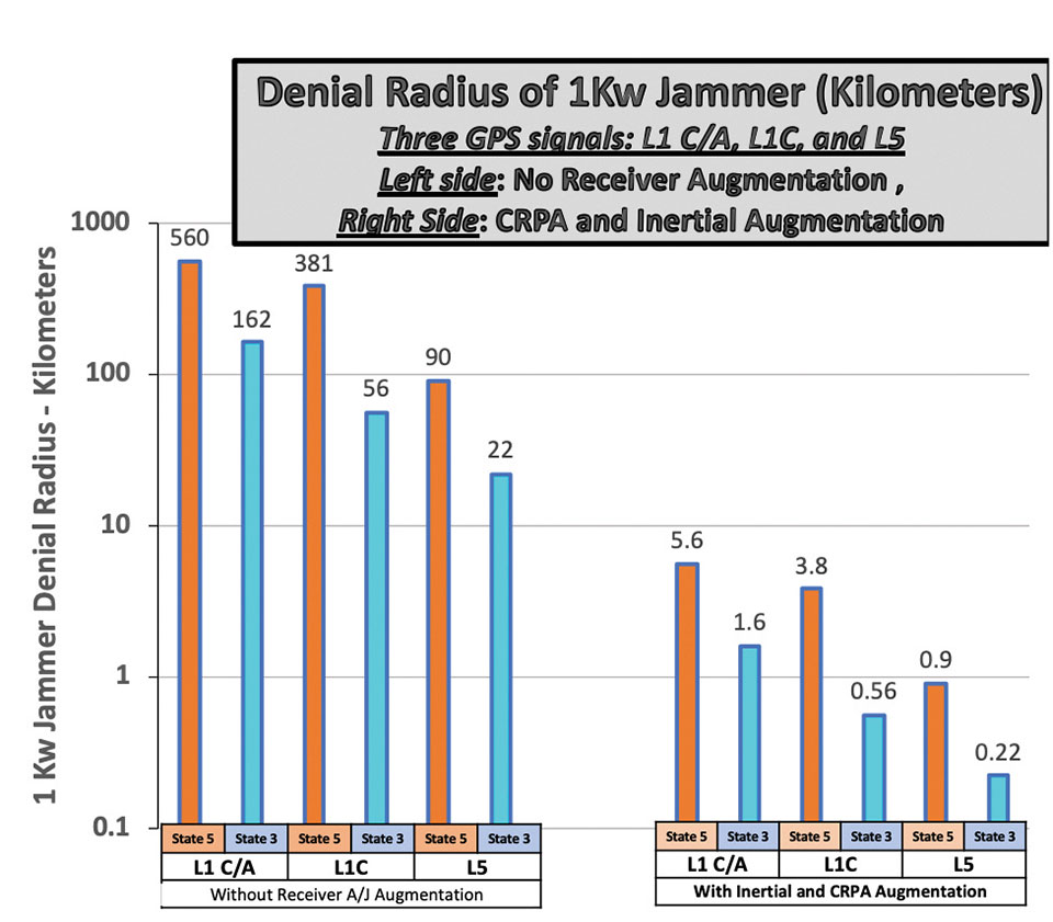
Summary of Receiver Toughening Options. Quantification of the selected, nominal receiver augmentations are summarized in FIGURE 1 for both full accuracy (State 5, centimeter-level accuracy in RTK) and for less accurate code tracking (State 3, meter-level accuracy). These results are shown with a logarithmic scale to accommodate the wide range of denial radii.
Figure 1. Effect of receiver augmentations on accuracy for both State 5 and State 3. (Image: Brad Parkinson)
The example shows that a 1-kW hostile jammer’s denial radius10 can be reduced by a factor of about 100, using the conservative example augmentations of inertial and CRPAs. Because area is proportional to radius squared, the effective denial area of an augmented receiver would be 1/10,000th of the unaugmented receiver, using the example values.
Reverting to code-only (State 3) tracking, it enables operating through higher levels of jamming, albeit with less ranging precision. All these receiver augmentations and tracking techniques would also offer a significant defense against any attempt to spoof (deceive) the position measurement. Again, none of these techniques are new; we demonstrated the capabilities at the original GPS Joint Program Office in 1978, more than 40 years ago. Today, many competent manufacturers are offering toughened GPS receivers with combinations and variations of these techniques.
GPS jamming tests at White Sands have caused aircraft interference, which could be largely avoided with toughened receivers. Here, M-code is tested on Joint Light Tactical Vehicle platforms in 2020. (Photo: Joe Bullinger/U.S. Navy)
Meeting Increasing Threats
Threats of both jamming and spoofing seem to have accelerated. Devices to perform these illegal acts are freely advertised on the internet. In fact, we read of incidents both in the United States and abroad.11 Near White Sands Missile Range in New Mexico, there have been GPS air traffic control outages due to authorized military operational jamming exercises. Such interruptions could be largely avoided if more robust (toughened) GPS receivers, with the enhanced jam resistance techniques outlined here, were in use.
News reports also highlight the spoofing issue. Hardening against this threat is also a task for toughening. A serious spoofing sequence usually starts with a strong jamming signal to cause the user’s receiver to break lock, followed by a strong false GNSS signal that causes false lock by the receiver. Using the false signal leads to a false position, of course. The first line of defense is to avoid the break-lock threat. Failing this, numerous self-check and authentication schemes can be used to avoid false positions.
A conclusion is that avoiding the break-lock jamming is a first line of defense against a spoofing attack. Of course, the toughening techniques to avoid this are the main subject of this paper. One well-known expert has stated that, for a well-designed receiver, a spoofing attack might deny the measurement of position, but should never cause false PNT. I will leave further discussion of spoofing to other authors.
Returning to disruptions of service in general, some have suggested many interference occurrences have gone unreported, because the typical user would not know where to make such a report. To remind the reader, the official reporting center is online at www.navcen.uscg.gov/?pageName=gpsUserInput.
In addition, the U.S. Federal Communications Commission (FCC) has repurposed a portion of the spectrum adjacent to the main GNSS L1 frequency (1575 MHz). The agency is converting the license holder’s original authorization to transmit a weak space-transmitted signal into a much stronger terrestrial system, potentially with thousands of transmitters. Extensive testing of civil GPS receivers by the U.S. Department of Transportation demonstrated that the planned repurposing will interfere with many existing receivers. Some observers call this disruption “legal jamming.”
Such a new spectrum use could have grave impacts on those existing receivers, notably aviation (especially helicopters and UAVs) and first providers. On the other hand, installing toughened replacement receivers would make the users virtually immune to this threat.
So, this begs the question: If the receiver toughening techniques are so effective, why are they not more prevalent?
Barriers to Adoption
Let’s examine the potential resistance to more extensive use of receiver augmentations.
Knowledge. This involves underestimating the threat to PNT and not understanding that toughening techniques are available. As mentioned above, threats to the fragile GNSS signals are growing.
There seems to be little interest in the U.S. government to monitor and suppress interference in the United States. Internationally, the reported incidents continue to increase.12 It is also reported that certain European aircraft manufacturers have installed advanced, deeply integrated inertial systems with civil GNSS receivers to defeat or “flywheel” through radio-frequency threats (particularly in the Middle East).
As this threat trend continues, GPS manufacturers and users must realize that many of these solutions will take time to authorize, implement and install. It appears that the media are not aware that not only are the toughening techniques outlined here feasible, but many manufacturers have product offerings that address these threats. Having off-the-shelf solutions will give the PNT user the opportunity to retrofit and defeat such threats.
Cost. The cost for a receiver to revert from State 5 to State 3 is zero, and all receivers that use Code 5 (for example, RTK) would naturally have this built in. Regarding use of other frequencies (such as L5) and modulations (L1C) rather than the original L1 C/A, there is some small cost associated, including the additional antenna for L5. Note that all modern cellphone chips, such as Qualcomm’s, have this capability — including integrated carrier-phase measurements — in a chip that is estimated to cost about $5. A potential barrier is that the L5 and L1C signals are not yet declared operational, but these newer GPS signals should be operational within about five years.
The costs of many inertial components (accelerometers and gyros) have plummeted in the last few decades with the proliferation of MEMS devices, particularly into cellphones and automobiles. Their power consumption has also decreased while their performance has steadily improved. Full IMUs are much more expensive, but are already installed on many commercial aircraft. Robust toughening with inertial sensors can be achieved, but requires deep integration and careful engineering.
Depending on their complexity, CRPA antennas can be a costly receiver augmentation. Very high-speed (330 MHz is available), 16-bit, A-to-D converters are at the heart of most of these phased-array devices. Some are priced at about $150 each. Applications with a high premium for PNT availability in the face of interference — such as commercial aircraft and cargo ships — should find them affordable. Aircraft manufacturers have resisted retrofitting existing aircraft with larger diameter CRPA antennas because of costs. For some of these applications, integration costs can be more than the costs of the receiver itself, particularly if not included in the original manufacture.
As the yearly sales of fully toughened receivers increase, the economies of scale should significantly reduce unit costs. Each application will make its own determination of affordability, based on risk.
Government restrictions. Civil use of CRPAs with four or more elements is restricted by ITAR. These are well-meaning restrictions on technologies that could be used against the United States by hostile military forces. Unfortunately, the phased-array antenna techniques are not only well understood and tested, but relatively inexpensive components are widely available on the open world market. In particular, the restriction on the number of CRPA elements for civil use should be completely removed. All potential enemies are well aware of the beam-steering method and have ready access to the parts to build them. Thus, the restriction is only harming civil users without affording any apparent improvement in general military posture.
Certified aviation receivers need approval for deep integration of inertial systems and multi-element CRPAs. (Photo: JasonDoiy/iStock/Getty Images Plus/Getty Images)
Gaining permission: FAA flight certifications. To be used in commercial aircraft operations, navigation equipment must be certified by the U.S. Federal Aviation Administration (FAA). Current, certified GPS aviation receivers have rudimentary toughening techniques, but gaining approval for deep integration of inertial systems and multi-element CRPAs must be completed. It is gratifying to hear that work is underway to do this.
Any civil solution for the United States must expand integrity monitoring beyond GPS to include all GNSS, and must be operationally included in the FAA’s integrity monitoring with WAAS.
Recommendation
In describing resistance to interference, I have introduced the idea of DRRR – Denial Radius Reduction Ratio. Also, I have used a 1-kW white-noise jammer as a standard threat for calculating the denial radius of various GPS receiver configurations. My recommendation is that equipment manufacturers specify their receiver offerings by stating their equipment’s denial radius against a “standardized” 1-kW EIRP white-noise jammer.
Summary
Media reports of interference to GPS may be accurate, but they generally do not recognize that available toughening techniques can largely defeat those interference threats. While exploring systems-level replacements or augmentations (such as LEO ranging or Loran) is worthwhile, GPS (or GNSS) still offers the greatest capability in combined terms of accuracy, integrity and coverage.
The goal of all PNT providers — GPS operators, certifiers and manufacturers — should be assured PNT, with the expected accuracy and availability. The described toughening techniques to do that have been known for decades, but have not been generally adopted by many critical civil users. Many manufacturers do offer civil products under existing government constraints.
The purpose of this article was to describe and advocate the solutions available to increase the robustness and toughening of civil GPS receivers. For example, readily available toughening augmentations for civil receivers can reduce the denial radius of interference by 99% or more. This implies that any denied area would be squeezed down to 1/10,000th of that experienced by an unaugmented receiver.
The payoff is high, and should be affordable to many high-end, safety-of-life users. Therefore, a renewed focus on toughening of GPS receivers is overdue. We discussed barriers to rapid adoption but, more than the specifics, it is crucial to fully and urgently embrace the goal of toughening receivers, particularly removing the ITAR restriction on antennas.
Opinions expressed in this article are those of the writer and should not be construed as the official position of the PNTAB or any U.S. government organization.
Notes
1. While not a part of the U.S. Department of Defense’s GPS operation, the FAA’s integrity signal (WAAS) is a GPS-type signal directly available and being used by almost all modern GPS receivers, including cellphones.
2. This is the ration of Denial Radius between, for example, unaugmented L1 C/A in State 5 and augmented L1C in State 3. Please see later footnote and graph.
3. Calculated as 10 (–15/20)
4. Of course, the more traditional dB measure of jammer resistance can (in most cases) be simply summed to estimate the total effectiveness. The use of DRRR gives a more intuitive calibration, particularly for non-technical persons who may not be at all familiar with dBs.
5. State 5 is the tracking mode that provides full accuracy; it requires tracking both the PRN code and the reconstructed carrier. It is required for RTK positioning, which is usually used for automatic control of machines or vehicles. It is most vulnerable to interference. Less vulnerable is State 3 tracking, which only provides code tracking, with precisions of perhaps a few meters.
6. Deliberate jamming using “matched spectrum” GPS-like modulations have also been employed in the Middle East. The toughening techniques described are also generally applicable, with appropriate rescaling. The matched spectrum is fundamentally used to improve the jammer spectrum efficiency.
7. See Michael Jones, “Anti-jam systems: Which one works for you?”, posted on gpsworld.com on June 14, 2017, for a survey of manufacturer offerings at that time. Named companies generally continue to offer improved, jam-resistant products.
8. Phased-array antennas, by their nature, distort phase and would probably have to be calibrated for precise operations such as RTK. Fortunately, we understand that this problem has been reportedly addressed and largely solved by the U.S. Navy’s JPALs program.
10. The denial radius results shown can be easily scaled for weaker or more powerful jammers. The scaling goes as simply the square root of the power ratio of a different size jammer to the 1-kW example. A 10-watt jammer is 1/100th the power of the example. The denial radius would then be one tenth of the example, which is the square root of 1/100.
11. “Ships have reported an increasing number of cases of significant GPS interference and jamming in recent months. The geographic areas with more than one reported incident include the eastern and central Mediterranean Sea, the Persian Gulf, and multiple Chinese ports.” (Source: www.gard.no/web/updates/content/30454065/gps-interference-and-jamming-on-the-increase).
“North Korea is using radio waves to jam GPS navigation systems near the border regions, South Korean officials said. The broadcasts have reportedly affected 110 planes and ships and can cause mobile phones to malfunction.” (Source: www.bbc.com/news/world-asia-35940542).
12. “Reports of GPS outages submitted by pilots from the cockpits of commercial flights show that disruptions to the navigation system, which was created and is maintained by the U.S. government, are now standard occurrence on the flight routes between North America and Europe and the Middle East, according to data from the European Organization for the Safety of Air Navigation, known as Eurocontrol.” Fortune Magazine, Nov. 1, 2020.
Innovation is the watchword in Washington this year. Amidst an ongoing supply-chain crisis and rising global trade tensions, policymakers have put renewed emphasis on U.S. leadership in such industries as semiconductors, wireless broadband and artificial intelligence — areas rightly seen as the “enabling technologies” of the 21st century.
Alongside chips and supercomputers is another innovation underpinning everything from our communications networks to financial transactions and air transportation: GPS technology. 2022 will see a flurry of activity to accelerate U.S. competitiveness for the modern economy and accelerating the modernization of our GPS constellation must place high on this list.
It’s no surprise that allies and adversaries alike have taken notice of GPS. While for decades U.S.-led GPS was the “only game in town” for global navigation satellite systems (GNSS) services, the current global picture is much changed. Russia, China, the European Union, Japan, India and other nations have explored, tested and deployed satellites to build out their own global or regional positioning, navigation and timing (PNT) networks and capabilities. The more recently deployed GNSS — including China’s BeiDou, which was completed in 2020 — represent a competitive threat by our international adversaries in spite of U.S. GPS technology advancements in performance and resilience. The potential loss of global leadership poses a dramatic challenge for U.S. interests.
Although our current GPS constellation continues to enable critical services that touch nearly every aspect of daily life, the oldest satellites were launched in the late 1990s. As new, more advanced GPS satellites go up in the sky, we can take several policy steps here on the ground to ensure that GPS remains the global standard — undermining attempts to create an information ecosystem independent of the United States and reliant on our international competitors.
Enter the United States’ GPS modernization program. Allocating the resources necessary to accelerate the launch of new GPS satellites will pave the way to keeping GPS globally competitive — both in defense and civil applications. Take accuracy, for starters. New GPS satellites will bring three times better accuracy than existing systems and up to eight times improved anti-jamming capabilities, both of which will keep us competitive and add critical security against domestic spoofers and foreign adversaries.
While U.S. firms should continue to create multi-constellation receivers that are interoperable with global PNT signals, U.S. policy should promote American technological leadership by accelerating modernization of the GPS space and control segments. Importantly, a necessary element of this technological leadership is development of a systematic roadmap to spur adoption of these new modernized features in civil applications. Establishing this clear pathway for civilian applications of a modernized GPS constellation is critical to ensuring that the potentially more than $1 billion of economic benefits added every day by the U.S. civil GPS sector are fully realized.
As Congress continues to focus on innovation and global competition, the GPS Innovation Alliance is committed to working with policymakers to promote the critical security, economic and diplomatic benefits to the United States of investing in next-generation GPS infrastructure.
Originally a product of the Sputnik era, GPS has demonstrated the very best features of competitive U.S. government investment. As the United States prepares for a renewed era of global competition, the promise today of invigorated support for GPS remains the same.
The United States must continue to lead by modernizing GPS and establishing a clear pathway for civilian applications of the improved constellation. (Image: matejmo/iStock/Getty Images Plus/Getty Images)
An off-the-shelf PC provides the computing power for complex GNSS driving simulations. (Photo: Racelogic)
By Julian Thomas Managing Director, Racelogic
Driving simulators are commonly used by vehicle manufacturers to expedite the test and development process of their many electronic systems. This not only saves the considerable time and expense of using a real car on a test track, but it is, of course, significantly more environmentally friendly.
LabSat simulators are used by many leading technology companies and car manufacturers to develop and verify the performance of their new products containing GNSS receivers. These tests are performed using either a pre-recorded or an artificially generated RF signal. This RF signal contains the combination of multiple satellite signals, which are decoded by the GNSS engine, tracking the artificial satellites as though they were real. Static or moving scenarios can be generated, and the user can select parameters to suit their own application, such as time, date and available constellations.
Julian Thomas Managing Director Racelogic
Recently, an automotive LabSat customer had a specific requirement to synchronize a GNSS receiver with the real-time trajectory data generated by one of their driving simulators. This was for a hardware-in-the-loop test rig where a human driver would navigate a route around a virtual test track, while the normal electronic systems reacted as if the vehicle were being driven around a real environment.
The challenge in this customer’s application was that the time delay between the trajectory coming from the simulator and the generation of the corresponding GNSS signals had to be less than 100 ms. This low latency was necessary to achieve realistic synchronization between the driver’s inputs and the resulting output from the GNSS-based device under test.
Traditionally, low-latency real-time simulators use bulky expensive hardware that relies on power-hungry field programmable gate arrays (FPGAs) to create the necessary satellite signals. However, due to the inevitable tick of Moore’s Law, and with some clever optimizations, your entry-level desktop PC now packs more than enough punch to simulate multiple constellations and signals with very low latency.
Using a standard PC to do the heavy lifting means that the hardware required to output the simulated signal is much easier to obtain, can be a lot simpler, and is considerably more cost effective. For example, an 8-core, 3-Ghz Intel i7 processor can generate the signals from 20 satellites in real-time, which normally is sufficient to simulate all but the most complex scenarios.
Our LabSat SatGen software has been continuously developed and optimized during the past 15 years, so it did not take us long to enable the reception of an NMEA trajectory stream with a latency of less than 100 ms. We then streamed this simulated data via USB to our LabSat Real-Time, which generated a corresponding RF signal that can be connected directly to the RF input of any modern GNSS engine.
Using a PC to generate the signals does not mean a loss of fidelity, with the resulting output achieving a repeatable position of less than 10 cm, while the trajectory data can be received at up to 100 Hz.
The resulting solution can take trajectory data from any kind of simulator that has an API to obtain real-time data, such as many popular off-the-shelf driving and flight software simulators, and use this to provide a real-time signal that can be utilized by the GNSS device under test.
Our future development roadmap includes synthesizing external signals, such as CAN-based sensors or inertial measurement units, and then synchronizing these signals with the incoming trajectory. With the amazing power of a modern PC, we are finding that this kind of complex simulation is now much more cost effective and easier to achieve.
Surveyors used ComNav equipment to construct a hospital in Burkina Faso. (Photo: ComNav)
Line of sight to GNSS satellites is sometimes obscured by buildings and trees, which also cause multipath, as does nearby water. These conditions require an RTK receiver with multipath mitigation. Often, surveying must occur on property corners or on uneven ground, where it is hard to place surveying equipment. For these reasons, reliability and accuracy are essential, especially in harsh environments. Ground control points require 1-2mm accuracy and topo surveys 1-2cm accuracy. Surveying for AEC also requires software that processes digital files.
ComNav has focused on GNSS core technology innovation and applications for 10 years. The Quantum III technology includes algorithms to suppress multipath and supports all GNSS constellations, allowing the users to acquire and keep RTK centimeter accuracy even in harsh environments. The built-in tilt IMU will help where the exact location to be surveyed is hard to reach. For example, the T300 Plus and N Series GNSS receivers support a maximum pole tilt of 60° and keep the compensation accuracy within 2.5cm, making the field work more efficient, convenient and reliable.
With the Survey Master software’s stake-out points, users can import DXF or DWG files directly and the software can stake out the point, line and surface in CAD.
In April 2021, the government of Burkina Faso used ComNav GNSS T300Plus to provide ground control points survey for the construction of a hospital.
The land security and topographic surveying were completed within only six days, less than half the time that had been scheduled for those tasks. This greatly expedited the construction of the hospital and helped with the fight against infectious diseases, including COVID-19.

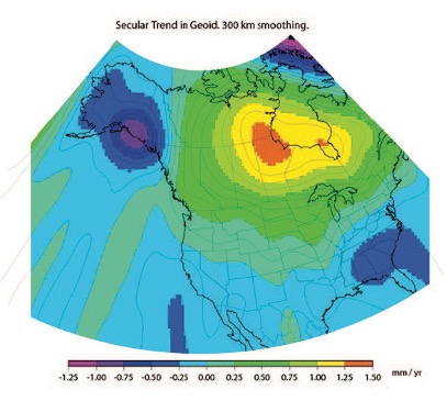
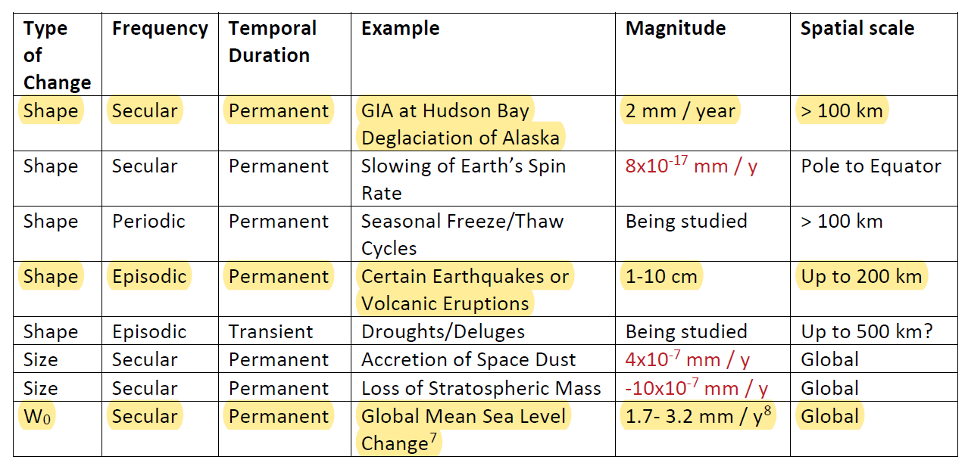
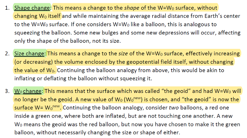
![Figure 32: Geoid rate over CONUS based on the GSFC mascon model [mm/yr] (Image: NOAA)](https://stage.globalpositioningnews.com/wp-content/uploads/2022/05/Geoid-rate-CONUS.jpg)
![Figure 33: Geoid rate over Alaska from GSFC mascon model [mm/yr] (Image: NOAA)](https://stage.globalpositioningnews.com/wp-content/uploads/2022/05/geoid-rate-alaska.jpg)