Blue Marble Geographics has released version 22.1 of Global Mapper, a GIS application that provides both novice and experienced geospatial professionals with a comprehensive array of spatial data processing tools.
Globe Mapper provides access to a variety of data formats and includes numerous spatial analysis tools at a genuinely affordable price.
The version 22.1 release includes enhancements to the software’s 3D Viewer including, a new Save 3D Views function and 3D View navigation tools to target the camera on specific features and lock the pivot axis around a feature of interest.
The data graphing and charting feature has been updated with support for creating graphs from multiple layers, and several new spatial operations functions have been added, including Union and Difference. As with previous releases, numerous new data formats are now supported including, support for exporting to COG (Cloud-Optimized GeoTiff) format and importing of IFC (Buildings) and GeoSLAM files.
“Every release of Global Mapper demonstrates Blue Marble’s commitment to continually expanding our software,” said Patrick Cunningham, Blue Marble President and CEO. “Version 22.1 includes countless improvements throughout the software but especially in 3D visualization and analysis, reflecting the rapidly increasing importance of 3D mapping.”
Blue Marble Application Specialists will be conducting a live webinar on Global Mapper v22.1 on March 3. During the hour-long presentation, scheduled to begin at 10 a.m. (U.S. Eastern Time), attendees will see the latest tools in action and will have the opportunity to ask questions about the new functionality. Registration is required.
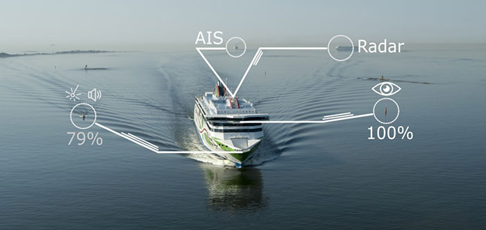
A day of ferry trips between Finland and Estonia became some of the best documented voyages in maritime history. Cameras, sensors, radio and satellite navigation receivers and even microphones recorded every instant of the crossings over the Baltic, gathering raw data for a new ESA-led project applying artificial intelligence (AI) to the situational awareness of shipping — as an important step to full autonomy.
The Tallink shipping company’s new 212.2 meter-long Megastar passenger and car ferry was fitted with data-gathering devices for its sailings on the busy stretch of sea between Helsinki and Tallinn.
The testing was overseen by a team from the Finnish Geospatial Research Institute (FGI) for an ESA project called Artificial Intelligence/Machine Learning Sensor Fusion for Autonomous Vessel Navigation, or Maritime AI-NAV.
“Our aim is to show how AI can be applied to achieve autonomous situational awareness, so that a ship can reliably sense its own environment,” said FGI’s Sarang Thombre.
Photo: European Space Agency
“Such autonomous systems would initially be deployed in support of human crews, for enhanced safety and efficiency – with crewless ships a much longer-term goal.
“The most experienced human ship captains will have the least trust in any single navigational device but will rather continuously cross reference between them. Similarly, our autonomous functionality will not be overly reliant on a single data source but combine and verify data from multiple sensors.
“Having gathered many gigabytes of data during our initial August field campaign, then again in October with more days planned in December, we are applying the results to train and test our data-fusing algorithms. A follow-up seagoing test will then verify their performance in practice.”
The Maritime AI-NAV team plans to employ a variety of sensor types, including satellite navigation receivers – also utilizing of Europe’s Galileo system — monocular and stereo cameras, standard radar, “laser radar” lidar and an array of microphones, along with “Automatic Identification System” radio signals. These AIS signals transmit position, size and routing information of all vessels above a certain class, as well as fixed infrastructure such as oil rigs or wind turbines.
“Satellite navigation lets the ship know where it is in the sea, while the other sensors let it know what is around it, which is essential for identifying and avoiding any obstacles,” Thombre said. “The different data sources operate across a variety of ranges — so radar and AIS provide longer range detection out to the horizon, while cameras and lidars come into their own at shorter distances. Plus we had a trio of microphones aboard the Megastar, determining the angle of arrival of sound from other ships. The challenge now is to fully integrate all these sources using machine learning, to build up a holistic picture.”
Maritime AI-NAV is supported through ESA’s Navigation Innovation and Support Programme, working with European industry and academia to develop innovative navigation technology.
FGI is joined in the Maritime AI-NAV consortium by Aalto University’s Sensor Informatics and Medical Technology group and maritime IT startup Fleetrange.
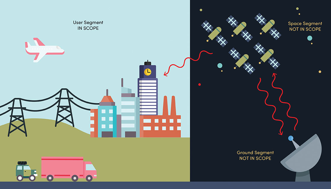
NIST’s new cybersecurity profile is designed to help mitigate risks to systems that use PNT data, including finance, transportation, energy and other critical infrastructure. While its scope does not include ground- or space-based PNT source signal generators and providers (such as satellites), the profile still covers a wide swath of technologies. (Image: B. Hayes/NIST)
The National Institute of Standards and Technology (NIST) has drafted guidelines for applying its Cybersecurity Framework to critical technologies such as GPS that use positioning, navigation and timing (PNT) data. Part of a larger NIST effort to safeguard systems that rely on PNT data, these cybersecurity guidelines accompany NIST efforts to provide and test a resilient timekeeping signal that is independent of GPS.
Formally titled the “Cybersecurity Profile for the Responsible Use of Positioning, Navigation and Timing (PNT) Services (NISTIR 8323),” the new guidelines are designed to help mitigate cybersecurity risks that endanger systems important to national and economic security, including those that underpin modern finance, transportation, energy and additional economic sectors.
The draft profile is part of NIST’s response to the Feb. 12, 2020, Executive Order on PNT. In early 2020, NIST sought public input regarding the general use of PNT data. The PNT profile will join the growing list of profiles created to help apply the NIST Cybersecurity Framework to particular economic sectors, such as manufacturing, the power grid and the maritime industry. The scope of the profile includes any system, network or other asset that uses PNT services, including systems that receive and rebroadcast PNT data.
While its scope does not include ground- or space-based source PNT signal generators and providers (such as satellites), the profile still covers a wide swath of technologies. Partly for this reason, NIST’s Jim McCarthy said that it is intended to be a foundational set of guidelines that PNT users can customize.
“The profile is meant to help a broad set of users address their cybersecurity needs,” said McCarthy, one of the draft’s authors. “Rather than focus on a single economic sector, we designed it to apply to all users of PNT. Agencies and companies can tailor it to their needs based on their particular cybersecurity risk and other sector-specific factors.”
As directed by the Executive Order, the profile can help organizations accomplish four tasks:
identify systems that use PNT data, and/or that propagate this data based on a source signal
identify PNT data sources, such as a GPS signal
detect disturbance to and manipulation of systems that use PNT services
manage the risks that come with responsible use of these PNT services
“Our premise is that there are organizations that may not realize they are using PNT data, or know how they are using it,” McCarthy said. “Part of our goal is to help them make these connections so they can protect their operations more effectively.”
The Executive Order also delegates to the Department of Commerce the critical task of providing a source of Coordinated Universal Time (UTC) that is independent of GPS. To this end, NIST also recently conducted initial tests of a special calibration service for companies, utilities or other organizations that wish to receive NIST’s version of the global time standard, UTC(NIST), through commercial fiber-optic cable.
The service aims to provide a time reference directly traceable to UTC(NIST) with an accuracy of 1 microsecond — good enough for telecom networks, the power grid and financial markets, and thereby boosting the resilience of accurate time distribution and the infrastructure sectors and subsectors that use timing services.
The initial link is a collaboration between NIST and OPNT, a commercial time-service provider based in Amsterdam, the Netherlands. While the work was led by researchers at NIST’s Boulder, Colorado, campus, the dedicated optical fiber connects the reference time scale at NIST headquarters in Gaithersburg, Maryland, to a facility in McLean, Virginia, that will ultimately serve as the hub for East Coast distribution of timing data.
OPNT has extended the initial fiber link to Atlanta, Georgia, about 800 kilometers from McLean. Preliminary data suggest that this link will be able to support the requirements of the Executive Order.
Fusing Automotive Radar and OBD-II Speed Measurements with Fuzzy Logic
SYN·ER·GY/ˈsinərjē/ noun: the interaction or cooperation of two or more organizations, substances, or other agents to produce a combined effect greater than the sum of their separate effects; from the Greek, “working together.” That is how the Oxford Dictionary defines this useful property that we often apply to business activities and other human interactions. But it can just as well describe the basis of an apparatus such as a navigation system that consists of several devices working together to produce a safer and more accurate result.
We all know that GPS or any GNSS for that matter doesn’t work everywhere all the time. For example, in built-up areas, signals can be blocked and reflected by buildings leading to positioning errors or complete outages. That is why it is quite common nowadays to combine a GNSS receiver together with an inertial measurement unit or IMU (often in the same package) to produce a more reliable solution for continuous navigation. But IMUs drift and so during an extended GNSS outage, the fidelity of the position reported by the GNSS plus IMU system will degrade with time. And so additional sensors must be added to the mix to improve the reliability of the navigation system. LiDAR, cameras, altimeters and so on have all been used severally or individually to augment the basic GNSS plus IMU combination. Self-driving cars, for example, use multiple sensors to provide safe navigation under specific conditions. Such specialized systems are quite expensive and so we might ask: Can the basic combination of GNSS and an IMU (or some of its components) be augmented by measurements already available in most vehicles or provided easily and inexpensively by equipment add-ons?
Yes. One measurement that helps is the forward speed of the vehicle. This is available from the vehicle’s on-board diagnostics computer system that tracks and regulates a car’s performance. Car manufacturers have adopted a standard for reporting data, the latest version of which is OBD-II. It is easy to interface to the OBD-II connector in a vehicle and extract the speed measurements – the same measurements displayed by the vehicle’s speedometer. Another potential source of speed measurements is the radar in most modern vehicles used for adaptive cruise control. That measurement is hard to acquire and has other limitations. But the idea to use radar as an input to a navigation system is a good one and easily obtained and installed radar units can be used instead.
But how do you optimally combine all of these sensor readings to produce reliable navigation? In the Innovation article this month, we take a look at how fuzzy logic can be used to get a reliable speed estimate, how that can be combined with accelerometer and gyroscope measurements to get position, velocity and attitude of a vehicle and, lastly, how that can be combined with GPS-derived position and velocity in an extended Kalman filter to produce an integrated navigation solution. Now that’s synergy.
Abosekeen
Standard land vehicles and self-driving cars have acquired precise navigation solutions to improve safety and assist drivers. GNSS is used as the primary source of the navigation solution for such applications. However, when driving in environments such as urban canyons, tunnels, or under bridges, GNSS signal reception deteriorates. Worse, it may suffer from a full outage. Because of this, we need a supplemental or backup system, such as an inertial navigation system (INS). The INS provides a complete navigation solution, and it is not affected by signal deterioration or jamming. GNSS/INS integration can achieve better accuracy than GNSS alone. However, such efficiency cannot be maintained during extended GNSS outages, especially with low-cost and commercial-grade inertial sensors for the INS. This drawback principally occurs because the INS solution suffers from accumulated error growth over time. This error causes path or trajectory drift, which becomes significant in the long term.
The fusion between an INS and a GNSS-based system provides a more robust solution than each system alone. In particular, INS/GNSS integration requires both systems to provide the vehicle with an accurate solution. However, when the vehicle is in challenging environments, the GNSS receiver cannot successfully update the integration filter, leaving the INS as the only source for the solution. When a GNSS outage is prolonged in some extreme situations, the solution quality deteriorates rapidly from INS drift. In particular, when using a micro-electromechanical system (MEMS) based inertial measurement unit (IMU), the drift rate significantly increases.
Several approaches have been introduced to overcome such drawbacks. Our reduced inertial sensor system (RISS) concept can be a replacement for the INS in land vehicle and ground robot applications. RISS can provide a complete navigation solution with fewer sensors than a standard INS. It is easily implemented for common land or self-driving vehicle navigation because it uses the vehicle’s on-board diagnostics standard II (OBD-II) device to determine the vehicle’s forward speed. INS requires two integration steps for positioning, but using the OBD-II speed measurements in the RISS mechanization requires only one.This reduction reduces the drift rate because it limits error accumulation from the integration process.
RISS depends mainly on OBD-II speed measurements to provide the land vehicle forward velocity. Unfortunately, these speed measurements are vehicle-specification dependent. Furthermore, these speed measurements are vulnerable to several types of error sources that can be categorized as deterministic (systematic) and non-deterministic (non-systematic). Deterministic errors come from wheel-diameter changes due to variations in temperature, pressure, tread wear, speed, unequal wheel diameters between the different wheels, inefficient wheelbase (track width), limited resolution and sample rate of the wheel encoders. Non-deterministic error sources include wheel slips, uneven road surfaces and skidding. Both groups of error sources negatively affect the velocity, traveled distance and heading estimations using the speed measurements from the OBD-II device.
Accordingly, we have made several RISS modifications to enhance performance, such as integration with a GPS receiver by enhancing the system design matrix for the integration filter. Moreover, an azimuth measurement update from magnetometers was added to the RISS/GPS integrated navigation system to provide azimuth updates during GPS outage periods, so the system can ensure more reliable positioning accuracy in challenging GNSS environments. Furthermore, we introduced a radar-based RISS to overcome OBD-II speed measurement errors. With this system, we demonstrated the superiority of using a frequency modulated continuous wave (FMCW) radar as a speed source instead of the one based on the OBD-II device. Automotive adaptive cruise control (ACC) mainly uses the Doppler measuring technique to measure the target’s (the vehicle ahead’s) relative distance and velocity. The primary radar unit’s radiation pattern is supposed to be a narrow beam to avoid other moving objects. Unfortunately, clutter affects forward-looking radar-collected data. Besides, extracting the onboard vehicle’s speed is difficult primarily because of the radar installation position.
We improved the use of ACC by modeling the linear and non-linear error components with Fast Orthogonal Search as a non-linear system identifier. This provided a more precise solution during outages extending from 60 seconds to 10 minutes. Furthermore, vehicle positioning using ACC was enhanced by extracting the primary and target vehicles’ relative distances under specific rules in urban canyons. These results encouraged us to introduce a fusion between the RISS and ACC, developing a more robust navigation system that relies on more than one sensor type.
In this article, we propose a smart fusion technique to produce more accurate velocity information from both the Doppler radar and the OBD-II speed measurements. Our new RISS mechanization for land vehicle navigation uses the fused speed from the radar and the OBD-II device with a vertical gyroscope and two transversal accelerometers.
3D-RISS MECHANIZATION
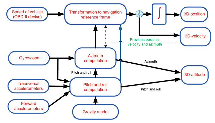
Our approach relies on a RISS incorporating a single-axis gyroscope, accelerometers, and speed measurements. Two accelerometers are used to estimate the pitch and roll angles instead of using two additional gyroscopes. Speed from the OBD-II device and heading information from the gyroscope aligned with the vehicle’s vertical axis enables the calculation of velocity, as shown in FIGURE 1. Calculating pitch and roll from accelerometers rather than gyroscopes retains RISS’s low cost while avoiding the gyroscope’s underpinning integration of velocity and position errors. When pitch and roll are calculated from accelerometers, the first integration of the gyroscope to obtain pitch and roll is eliminated, and thus the error in pitch and roll is not proportional to time integration.
FIGURE 1. Block diagram of speed measurements from the OBD-II device and RISS mechanization. (Image: Authors)
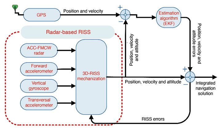
ACC-RADAR-BASED RISS
The radar-based RISS mechanization can provide a complete navigation solution (including 3D position, velocity and attitude) using a reduced number of sensors compared to the classic INS. It consists of longitudinal and transversal accelerometers, one vertical gyroscope and one radar unit (see FIGURE 2). In this mechanization, the OBD-II-device-related measurements are replaced by those extracted from the FMCW radar.
Data fusion is the process of combining data from multiple sensors and related information to achieve more specific inferences than can be achieved by using a single, independent sensor. Fusion processes are often categorized into three modes — low, intermediate and high-level fusion:
Data level combines several sources of the same type of raw preprocessed data to produce a new data set expected to be more informative and useful than the inputs.
Feature level combines features such as edges, lines, corners, textures or positions into a feature map used for the segmentation of images, detection of objects, and so on.
Decision level combines decisions from several expert modes. Methods of decision fusion are voting, fuzzy logic and statistical methods.
Various approaches for multi-sensor data fusion including weighted average, Bayesian estimators, adaptive observers, algebraic functions, fuzzy logic, neural network, soft computing, non-linear system fusion, and Kalman. Drawbacks of these methods include:
the necessity of adding new sensors to the system.
use of linear estimation models that need previous knowledge of signal statistics.
the presence of more than one faulty signal — an essential limitation of the performance.
the need to understand the behavior of the system to generate governing rules.
We used a data-clustering approach, which divides the data from a particular set into subsets (clusters) based on similarity. It could be defined as a reorganizing process for the dataset.
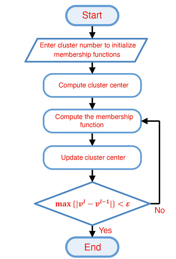
Fuzzy C-means (FCM) Algorithm. The FCM clustering algorithm represents the “fuzzify” step in the fuzzy system and is based on the minimization of an objective function called the C-means functional. The FCM algorithm (FIGURE 3) computes the standard Euclidean distance norm, which induces hyperspherical clusters. Hence it can only detect clusters with the same shape and orientation because the common choice of the norm-inducing matrix is the identity matrix. Three parameters in this algorithm have to be determined at the beginning: the number of clusters, the weighting parameter representing the system’s fuzziness, and the ending threshold, respectively.
FIGURE 3. FCM flowchart. (Image: Authors)
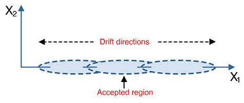
Cluster Number Selection. The FCM algorithm required predefining the number of clusters (Figure 3). This number can be entered randomly, taking iterations and time to converge to the best number, or be calculated. Many methods could be used, such as the validation parameters but only in an offline mode, or by using the data distribution itself and calculating the probability density function (PDF) by first calculating the data’s kernel and then calculating the PDF. This process can be done using the smooth kernel density estimator (SKDE), which is a powerful real-time approach. The main idea is that the measurements values drift in two directions around the acceptable region of measurements (see FIGURE 4). The number of clusters has to be determined in every instance of measurement. From the same figure, the partitions may be three if the drift was in two directions from the accepted region or may be two partitions if the drift at any instance were to the left or to the right direction (one direction drift).
FIGURE 4. Measured data partioning. (Image: Authors)
Subsequently, the number of clusters is determined according to the following two rules, based on the kernel estimator’s maximum peak location: If the maximum peak of the SKDE is left- or right-skewed, then the number of partitions is two; if the maximum peak of the SKDE is centered, then there are three.
METHODOLOGY
The methodology of the implementation of our approach is divided into two parts. The first part utilizes the FCM explained in the previous sections to produce a fused vehicle forward speed from the radar and the OBD-II device. The second part uses the fused speed in the INS mechanization instead of using one sensor only. Further, the mechanization output is integrated with the GPS receiver to establish a more accurate navigation system.
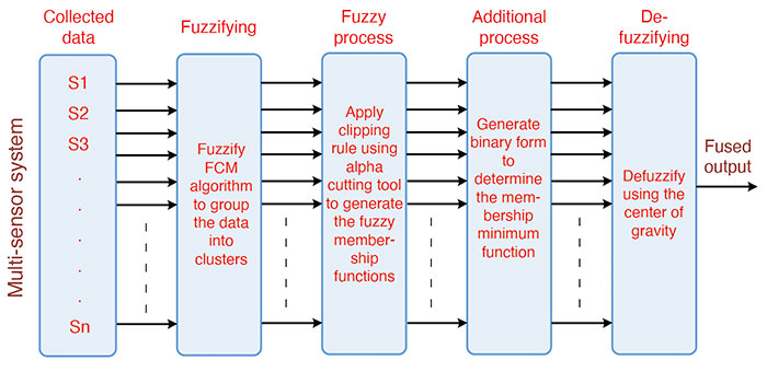
Sensor Fusion using Fuzzy Clustering. The data-fusion technique using the fuzzy clustering algorithm (FIGURE 5) consists of five main parts:
collecting data from the environment by using multiple sensors.
grouping the collected data by using the FCM algorithm in cluster form (“fuzzification”).
applying the fuzzy clipping rule using a cutting tool (fuzzy process).
making use of the clipping-rule properties to perform the fusion mechanism (additional process).
using the mean of the minimum to estimate the fusion output (“de-fuzzification”).
FIGURE 5. Sensor data fusion mechanization. (Image: Authors)
The first part is concerned with setting the sensors for measuring a particular phenomenon from the environment. The second part is to “fuzzify” these measured data, using the FCM to separate the sensors’ data to a certain number of clusters with membership matrix and cluster centers. The fuzzy process deals with the output clusters and membership functions through a fuzzy process called the fuzzy clipping rule. This rule divides the membership function into two regions: the upper region of the cutting threshold, which is clipped and is useless in the fuzzy environment, and the lower region from the cutting threshold, which is the useful region in the fuzzy environment.
Additional processes are applied to benefit from the previous stage — the existence of two regions, one useful, and the other not. This process aims to distinguish between the membership’s functions of the clusters. This could be achieved by generating a binary code that represents the membership function of the clusters. This binary code is generated by comparing the membership function with the threshold value. After the clustering process, each cluster membership function is represented as a binary code. The creation of this code depends upon the membership functions for the clusters and a variable threshold level.
The defuzzification part aims to extract the suitable value and in the same units as those of the measurements. This part produces the fusion output. This output comes from the minimum binary code, which denotes the selected suitable cluster membership function. This cluster contains the optimum solution. This solution or the fusion process output is determined by the centroid of the selected membership function.
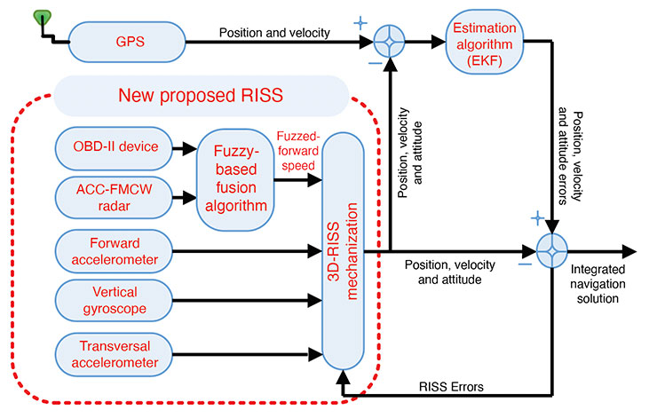
Fusion-Radar-RISS/GNSS Integrated Navigation System. In this part of our technique, the fusion algorithm’s output is used in producing a full navigation solution as a control input of the RISS mechanization. This solution is subsequently integrated with the GPS receiver in a loosely coupled scheme using an extended Kalman filter (EKF). The overall proposed integrated navigation system is shown in FIGURE 6.
We carried out the experimental work to verify the proposed navigation system’s effectiveness by traveling real road trajectories. The testbed equipment was mounted inside and outside the test van.
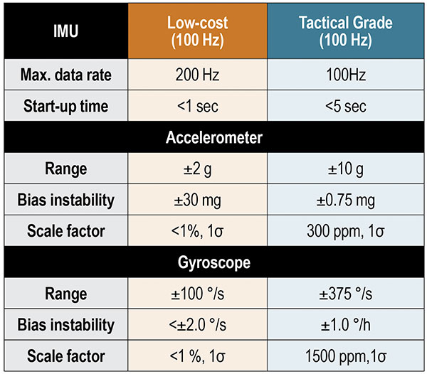
The interior testbed coincides with the van axes. It was rigidly and firmly fixed in the rear seat location using a standard seat chassis. For inertial sensors, we used both a low-cost MEMS IMU and a tactical-grade IMU. The specifications of these units are shown in TABLE 1.
TABLE 1. Performance characteristics of IMUs.
We used a dual-frequency GPS receiver with an output rate of 1 Hz. The tactical-grade IMU includes three fiber-optic gyroscopes and three MEMS accelerometers. The tactical-grade IMU and the GPS receiver were integrated using an off-the-shelf assembly developed by the manufacturer to provide a fully integrated, tightly coupled GNSS/IMU system that delivers a highly accurate 3D navigation solution. This tightly coupled integrated system from the manufacturer is used as a reference to compare the performance and the effectiveness of our proposed methods.
The FMCW radar development kit from the manufacturer was mounted on the front bumper. The unit’s working frequency is 24.5 GHz with a maximum frequency span of 1.5 GHz, a maximum update rate of 10 Hz, a maximum detectable speed of 215 kilometers/hour, and a 3 dB-beamwidth angle of 8.5°. The chirp frequency spans were adjusted to be 0.125 GHz. The maximum coverage range was 30 meters, and the minimum was 0.5 meters.
RESULTS AND DISCUSSION
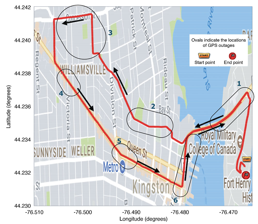
We conducted a road test with the proposed approach in the downtown area of Kingston, Ontario, Canada, in August 2017.
The trajectory followed is shown in FIGURE 7 projected on a Google map with the approximate locations of the outages. The reference is plotted in red, and the black arrows mark the direction of motion.
FIGURE 7. Road test trajectory with ovals indicating the approximate locations of GPS outages. (Image: Author)
Performance Evaluation. The proposed system performance was tested over six simulated outages. The outages have been selected to contain several dynamics such as turns, consecutive turns, stopping, crossing intersections, and straight driving. Furthermore, the outages occurred at different speed levels. The proposed system performance was compared to the traditional RISS/GPS and Radar/RISS/GPS integrated navigation system. The comparison criteria are 2D-position root-mean-square error (RMSE) and the maximum errors.
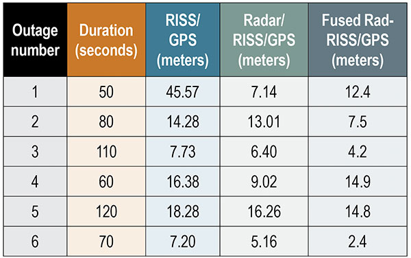
We compared our results using the radar-only versus OBD-II device test. TABLE 2 shows the RMSE of the 2D-position from the three systems in meters. Notice that the proposed system’s performance is better than the other two systems during four of the six outages. This result was achieved using the smart fusion technique to fuse the FMCW radar and the OBD-II speed measurements. Accordingly, the obtained speed is positively affecting the overall system performance.
TABLE 2. 2D-Position RMS-error for the low-cost INS unit during outages.
The average 2D-position RMSE reached 18.24 meters when using the OBD-II speed measurements only and 9.5 meters when using the radar only. On the other hand, the RMSE reached 9.4 meters when using the fusion between the two systems. The improvement percentage was 48.4% when applying the proposed integrated navigation system and 47.8% when using the radar-based system. The results show that the proposed system outperformed the other systems in outages 2, 3, 5 and 6 but did not do better than the radar-based system in outages 1 and 4. We highlight three outages.
The first outage had two left turns after a stop sign over a slippery road. This outage lasted for only 50 seconds, but the system’s behavior was due to wrong measurements combined with a complicated driving scenario when using the traditional RISS/GPS. On the other hand, the radar-based RISS/GPS produces a better solution because of having better velocity measurements in the mechanization, which provides the navigation filter with a better navigation solution. The proposed system limits the drift to around 16.7 meters, while the traditional system had a 68.7-meter drift in its solution.
The proposed system based on the fusion between both speed sensors — OBD-II and radar — could not compete with the radar because of the enormous gap between the two sensors and the lack of extra sensors. Despite that, the system produced a solution with 2D-RMSE of 22 meters, which is also better than the traditional RISS based on the OBD-II device and close to the results from fusing the radar. This problem can be solved by using an extra radar unit, typically installed with an ACC system. The system usually uses six radar units, two in the front and four at the vehicle’s corners.
The second outage duration was 80 seconds and contained two consecutive turns, right then left. The radar-based system reduced the solution drift from 28.13 to 23.58 meters. In contrast to the previous outage, the proposed system reduced the 2D-position maximum error to 14.2 meters. The proposed system’s result is superior to the radar-based system, which performed better in the previous outage because the OBD-II and radar measurements gap is not as large as the previous outage. The dynamics, the average speed and the road surface differ from the first outage.
The third outage was chosen to be a slight turn and mostly straight driving with an average speed of 60 kilometers/hour. This outage lasted for 110 seconds, and the proposed system holds the solution error growth down to 8.9 meters. The traditional system had a higher error growth rate and held it to 20.6 meters, and the radar-based system error reached 14.92 meters. This outage contained fewer dynamics when compared to other outages. Moreover, the slippage and false counting by the OBD-II device was not as considerable as in the first outage.
CONCLUSIONS AND FUTURE WORK
The performance of using a multi-sensor data-fusion technique based on fuzzy clustering successfully fuses the data measured by both the radar and the OBD-II device to produce a more robust forward speed of a moving land vehicle. The proposed system performance tested during six simulated GPS outages containing various dynamics significantly improved the overall navigation system, especially when the GPS signals were blocked. Finally, the fusion between multiple sensors leads to better performance if there are enough sensors or a fault-detection system to prevent the faulty sensor from biasing the fusion results. Moreover, the results demonstrate the superiority of the proposed fused radar RISS/GPS over each system alone.
As an extension to work reported here, we plan to apply our approach with an extra number of sensors to avoid the kind of drift that happened in outage number one. In addition, we suggest that a sensor fault-detection smart algorithm be added to the system to detect and control faulty sensors.
ACKNOWLEDGMENT
This article is based on the paper “Enhanced Land Vehicle Navigation by Fusing Automotive Radar and Speedometer Data” presented at ION GNSS+ 2020 Virtual, the 33rd International Technical Meeting of the Satellite Division of The Institute of Navigation, Sept. 21–25, 2020.
MANUFACTURERS
Our testbed used a Crossbow (now Moog Crossbow, www.moog.com) MEMS-grade XBOW IMU300CC IMU and a NovAtel/Hexagon (www.novatel.com) IMU-CPT tactical-grade IMU. We also used a SPAN-OEM4 or SPAN-SE NovAtel/Hexagon dual-frequency GNSS receiver. The radar development kit used is a Sivers IMA (now Sivers Semiconductors, sivers-semiconductors.com) RK1001K/00.
ASHRAF ABOSEKEEN is a lecturer in the Department of Avionics Engineering, Military Technical College, Cairo, Egypt. He received a B.Sc. and M.Sc. in electrical engineering from the Military Technical College in 2004 and 2012, respectively. He received his Ph.D. from the Department of Electrical and Computer Engineering, Queen’s University, Kingston, Ontario, Canada, in 2018.
UMAR IQBAL is an assistant clinical professor in the Department of Electrical and Computer Engineering, Mississippi State University. He completed his Ph.D. in electrical and computer engineering at Queen’s University in 2012.
ABOELMAGB NORELDIN is a professor in the Department of Electrical and Computer Engineering, Royal Military College of Canada, Kingston, Ontario with a cross-appointment at both the School of Computing and the Department of Electrical and Computer Engineering, Queen’s University.
“Seen & Heard” is a monthly feature of GPS World magazine, traveling the world to capture interesting and unusual news stories involving the GNSS/PNT industry.
Lost and found
Taking video from an airplane window 300 feet up carries its share of risks, discovered Brazilian documentary filmmaker Ernesto Galiotto. The bad news: A strong wind snatched his iPhone 6 from his hand. The good news: GPS enabled him to recover the phone, which suffered only a minor crack in its protective cover. The best news: The phone captured the entire 15-second drop on video. The incident happened over Peró beach 75 miles east of Rio de Janeiro, reported Brazilian news outlet G1.
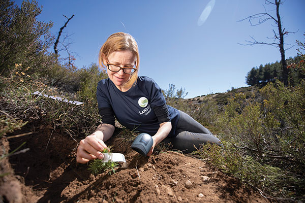
Photo: Land Life Company via Trimble
Finding particular trees in the forest
Locating and documenting a single tree in a forest planting can be difficult. Technicians at Land Life, an Amsterdam-based land restoration company, have switched from using QR codes and readers for tree identification to GNSS. By replacing the QR codes with accurate GNSS positioning, Land Life produced a four-fold increase in monitoring productivity. The company measures sapling height and health and combines that data with tree species, location, soils and environmental conditions to support planning and care. Field teams now use a Trimble R1 GNSS receiver to stream positioning data via Bluetooth to their smartphones.
Screenshot from video of Escoffier’s rescue/VendéeGlobe
Answering an SOS
Yacht skipper Kevin Escoffier faced disaster during the Vendée Globe solo round-the-world sailing race. His yacht was pounded apart in raging seas 840 nautical miles southwest of Cape Town, South Africa. Once his raft hit the water, its rescue beacon activated. Through the Cospas-Sarsat service, the signal moved from Galileo satellites to ground stations in Toulouse, France, to Canberra, Australia, then to race directors, who sent the closest competitor to assist.
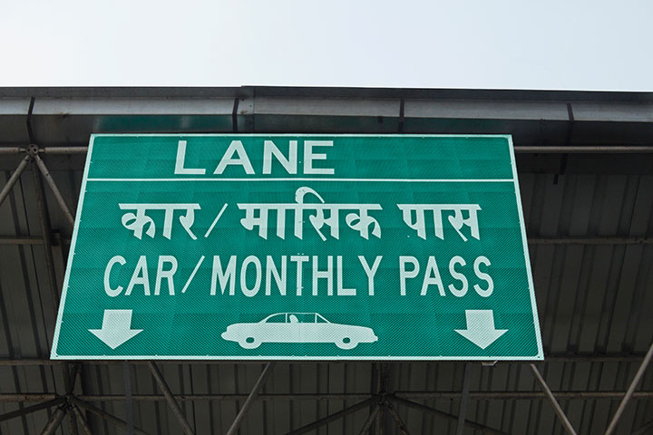
India will be free of toll booths in two years, said Nitin Gadkar, the country’s transportation minister. According to the Times of India, the government will roll out GPS-based tolling across its national highway sytem. Tolls will be deducted directly from drivers’ bank accounts based on distance traveled. While commercial vehicles registered after January 2019 have tracking systems, the government has yet to outline plans to install GPS receivers in older private vehicles.
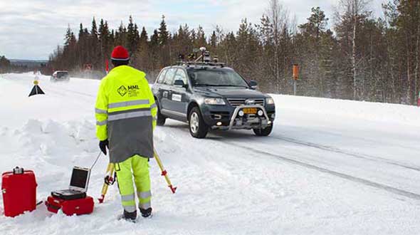
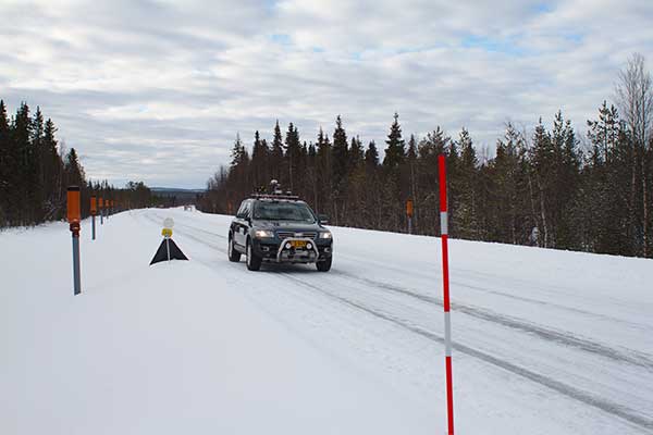
An ESA-supported project is testing autonomous vehicles on an intelligent road in Lapland, Finland.
Known as Snowbox, this 10-km stretch of forest-lined roadway on Finland’s E8 highway has been specially equipped for autonomous driving tests, ESA said. Containing cameras, “laser radar” lidar, ultra-wideband antennas and reflective panels, the road itself is underpinned by power and fibre optic lines, and embedded with pressure sensors to record road surface conditions and the speed and type of vehicles driving along it.
Known as Snowbox, this 10-km stretch of forest-lined roadway on Finland’s E8 highway has been specially equipped for autonomous driving tests, including FinnRef GNSS reference stations, as seen here. (Photo: ESA)
“If autonomous vehicles can drive well here, they can drive almost anywhere,” said Sarang Thombre of the Finnish Geospatial Research Institute, who’s managing the Arctic-PNT project. “Our project aimed at ensuring in particular that the precise positioning required by autonomous systems was available here, to establish this test site is indeed somewhere that driverless vehicle manufacturers should employ for testing. We carried out experiments with a robotic car over two successive seasons to show that the necessary precise positioning, down to 20 cm, is indeed accessible.”
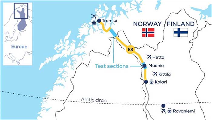
Snowbox is also linked to the FinnRef network of satellite navigation reference stations, to deliver corrections for precise satnav positioning. By performing positioning measurements continuously at fixed locations, these reference stations serve as a standard, allowing the identification of measurement errors to boost positioning accuracy on a localized basis, ESA added.
Snowbox map. (Photo: ESA)
“The Arctic is a difficult environment for autonomous driving in general,” Thombre said. “Signal disturbance due to the ionosphere, the electrically charged layer of the atmosphere, degrade satellite navigation performance. This effect is more pronounced in the Arctic region. And satnav augmentation systems also face challenges.
“Because their signals are broadcast from geostationary satellites, they are only viewable here at an elevation of up to 10 degrees above the horizon. And mobile coverage — useful for providing correction data from reference networks — is also inconsistent.
“In addition, possibility of mists and fog, snowstorms and rainfall make it difficult for cameras and lidar, while ice and snow on the road means wheel speed sensors may slip. And temperatures that can plunge down to below -30°C can impede the performance of electronics.”
The Arctic-PNT team’s testing was based around a robotic car crammed with sensors and recording equipment. Called Martti, the vehicle was supplied by Finland’s VTT Technical Research Centre.
Snowbox test roadway. (Photo: ESA)
“While Martti is capable of autonomous driving, we drove it manually,” Thombre said. “We were using it to capture all the data we needed. We started off using solely satellite navigation – including Europe’s Galileo and EGNOS – progressively adding more and more augmentation data, including in-car sensors, and corrections from the FinnRef stations, to reach the all-important precise positioning threshold of 20 cm.
“To access the FinnRef corrections from the car systems we tested out various mobile sim cards. Adding to the challenge, we crossed an international border, because part of the E8 highway is instrumented on the Norwegian side as well — called Borealis.”
The Snowbox infrastructure was established along the E8 because, while it is a remote roadway it is also economically important, with trucks heading south from Arctic fisheries.
The Arctic-PNT test campaigns, starting from 2018, gave a positive bill of health to the Snowbox, which is available for experiment campaigns. The campaigns were supported through ESA’s strategic initiatives for the Arctic region.
Feature image: The Arctic-PNT team’s testing was based around a robotic car crammed with sensors and recording equipment. Called Martti, the vehicle was supplied by Finland’s VTT Technical Research Centre. (Photo: ESA)
By Danny Baird NASA’s Space Communications and Navigation program office
The Artemis generation of lunar explorers will establish a sustained human presence on the Moon, prospecting for resources, making revolutionary discoveries and proving technologies key to future deep space exploration.
To support these ambitions, NASA navigation engineers from the Space Communications and Navigation (SCaN) program are developing a navigation architecture that will provide accurate and robust position, navigation and timing (PNT) services for the Artemis missions. GNSS signals will be one component of that architecture. GNSS use in high-Earth orbit and in lunar space will improve timing, enable precise and responsive maneuvers, reduce costs, and even allow for autonomous, onboard orbit and trajectory determination.
On Earth, GNSS signals enable navigation and provide precise timing in critical applications like banking, financial transactions, power grids, cellular networks, telecommunications and more. In space, spacecraft can use these signals to determine their location, velocity and time, which is critical to mission operations.
“We’re expanding the ways we use GNSS signals in space,” said SCaN Deputy Director for Policy and Strategic Communications J.J. Miller, who coordinates PNT activities across the agency. “This will empower NASA as the agency plans human exploration of the Moon as part of the Artemis program.”
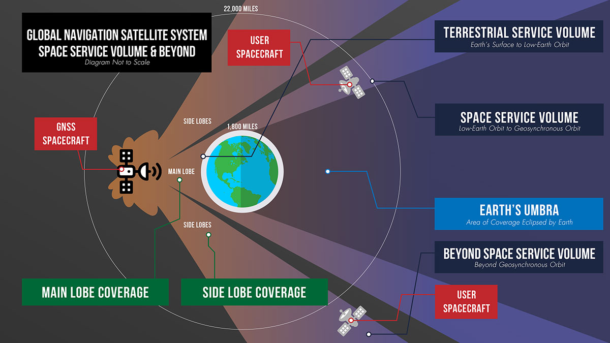
Spacecraft near Earth have long relied on GNSS signals for PNT data. Spacecraft in low-Earth orbit below about 1,800 miles (3,000 km) in altitude can calculate their location using GNSS signals just as users on the ground might use their phones to navigate.
This provides enormous benefits to these missions, allowing many satellites the autonomy to react and respond to unforeseen events in real time, ensuring the safety of the mission. GNSS receivers can also negate the need for an expensive onboard clock and simplifies ground operations, both of which can save missions money. Additionally, GNSS accuracy can help missions take precise measurements from space.
Expanding the Space Service Volume
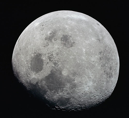
This photograph of a nearly full Moon was taken from the Apollo 8 spacecraft at a point above 70 degrees east longitude. Mare Crisium, the circular, dark-colored area near the center, is near the eastern edge of the Moon as viewed from Earth. (Image: NASA)
Beyond 1,800 miles in altitude, navigation with GNSS becomes more challenging. This expanse of space is called the Space Service Volume, which extends from 1,800 miles up to about 22,000 miles (36,000 km), or geosynchronous orbit. At altitudes beyond the GNSS constellations themselves users must begin to rely on signals received from the opposite side of the Earth.
From the opposite side of the globe, Earth blocks much of the GNSS signals, so spacecraft in the Space Service Volume must instead “listen” for signals that extend out over the Earth. These signals extend out at an angle from GNSS antennas.
Formally, GNSS reception in the Space Service Volume relies on signals received within about 26 degrees from the antennas’ strongest signal. However, NASA has had marked success using weaker GNSS side lobe signals — which extend out at an even greater angle from the antennas — for navigation in and beyond the Space Service Volume.
Since the 1990s, NASA engineers have worked to understand the capabilities of these side lobes. In preparation for launch of the first Geostationary Operational Environmental Satellite-R weather satellite in 2016, NASA endeavored to better document side lobes’ strength and nature to determine if the satellite could meet its PNT requirements.
“Through early on-orbit measurement and documentation of the GNSS side lobe capabilities, future missions could rest assured that their PNT needs would be met,” said Frank Bauer, who began the GNSS PNT effort at NASA’s Goddard Space Flight Center in Greenbelt, Maryland. “Our understanding of these signal patterns revealed a host of potential new GNSS applications.”
Navigation experts at Goddard reverse-engineered the characteristics of the antennas on GPS satellites by observing the signals from space. By studying the signals satellites received from GPS side lobes, engineers pieced together their structure and strength. Using this data, they developed detailed models of the radiation patterns of GPS satellites in an effort called the GPS Antenna Characterization Experiment.
While documenting these characteristics, NASA explored the feasibility of using side lobe signals for navigation well outside what had been considered the Space Service Volume and in lunar space. In recent years, the Magnetospheric Multiscale Mission (MMS) has even successfully determined its position using GPS signals at distances nearly halfway to the Moon.
A graphic detailing the different areas of GNSS coverage. (Image: NASA)
GNSS at the Moon
To build on the success of MMS, NASA navigation engineers have been simulating GNSS signal availability near the Moon. Their research indicates that these GNSS signals can play a critical role in NASA’s ambitious lunar exploration initiatives, providing unprecedented accuracy and precision.
“Our simulations show that GPS can be extended to lunar distances by simply augmenting existing high-altitude GPS navigation systems with higher-gain antennas on user spacecraft,” said NASA navigation engineer Ben Ashman. “GPS and GNSS could play an important role in the upcoming Artemis missions from launch through lunar surface operations.”
While MMS relied solely on GPS, NASA is working toward an interoperable approach that would allow lunar missions to take advantage of multiple constellations at once. Spacecraft near Earth receive enough signals from a single PNT constellation to calculate their location. However, at lunar distances GNSS signals are less numerous. Simulations show that using signals from multiple constellations would improve missions’ ability to calculate their location consistently.
To prove and test this capability at the Moon, NASA is planning the Lunar GNSS Receiver Experiment (LuGRE), developed in partnership with the Italian Space Agency. LuGRE will fly on one of NASA’s Commercial Lunar Payload Services missions. These missions rely on U.S. companies to deliver lunar payloads that advance science and exploration technologies.
NASA plans to land LuGRE on the Moon’s Mare Crisium basin in 2023. There, LuGRE is expected to obtain the first GNSS fix on the lunar surface. LuGRE will receive signals from both GPS and Galileo, the GNSS operated by the European Union. The data gathered will be used to develop operational lunar GNSS systems for future missions to the Moon.
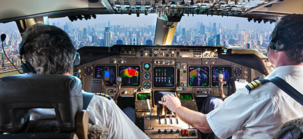
GNSS is a critical single point of failure for navigation in the aviation industry. A new white paper published by Egis says it’s time for the industry to get rid of legacy navigation aids (NavAids) and catch up technologically with the rest of the communications industry.
Current navigation backups are ground-based navigation aids such as distance measuring equipment (DME). These use post-World War II technologies, with very low spectrum efficiency. Some might find it surprising to learn that they are still using Morse code.
While difficult to jam due to their strong signal, current navigation aids are not cyber secure. Due to their spatial distribution, they can be limited in their support to PBN (performance-based navigation) or any new concept of operations.
The horizontal positioning error was measured under 10 m, so the LDACS-NAV would easily meet RNP 0.3 requirements.
Legacy NavAids — NDB (non-directional beacon), ILS (instrument landing system), VOR (VHF omnidirectional range) and DME — all require a specific frequency band, various equipment, and airborne and ground antennas.
As a result, the average commercial airliner can carry around seven specialized navigation antennas, and as many as 20 when accounting for all the other communication, navigation and surveillance (CNS)functions. Having different radio systems is adding redundancy but makes the aircraft and the ground equipment very costly, as well as difficult to engineer and to maintain.
Two major problems could affect the aircraft industry. First, software-defined radio, and powerful low-cost radio systems are available to the public and any ill-intended person could interfere, deactivate or worse, divert these vulnerable systems from their purposes. Second, spectrum is a finite and fixed asset (aviation uses 14% of the total available spectrum).
Why hasn’t this problem been solved already?
There are no market incentives for air navigation service providers (ANSPs) and airlines to make expensive investments in ground infrastructures and aircraft retrofits. With an average lifetime of 25 years per plane, commercial fleets take a long time to be renewed.
Also, the aviation spectrum is protected, which has led to complacency and a lack of pressure to use the latest technologies to improve spectrum efficiency.
Stakeholder Coordination. States, ANSPs, airlines, airports, aircraft manufacturers, communications providers and system providers all have their own interests and perspectives, which increases the difficulty in developing and maintaining a global CNS roadmap.
Deployment. Once a roadmap is agreed on, the deployment challenge remains. For instance, the retrofit compliance date for ADS-B was pushed back from June 2020 to to June 2023 due to the pandemic. The capacity of aviation to evolve depends on when the operational and commercial benefits are clear, such as when GNSS was implemented for navigation.
The Human Factor. Human factors have to be considered for any critical change in aviation. Pilots are trained on navigation aids and GPS, and used to communicating by VHF voice with air traffic control officers. This is the reason why the evolution of navigation and communication systems must be seamless with current systems or require an in-depth human-factor risk assessment.
Potential Solutions
To future-proof aviation and performance-based operating procedures, aircraft need both a broadband, IP-based datalink capable of VoIP and a secure, cost-effective alternative positioning, navigation and timing (A-PNT) system as a back-up to GNSS. Today, GNSS backup is the 70-year-old DME — using the signals from multiple DMEs, aircraft can locate themselves with reasonable accuracy.
The main choices to replace the DME are either an enhancement of DME systems (Multi-DME RAIM, eDME, Mosaic DME) or an A-PNT solution (LDACS-NAV, WAM-TISb, SSR mode N, eLoran).
If we look at the most mature solutions, the DME/eDME and the LDACS-NAV are the main options, and they represent a real dilemma.
DME/DME. This solution represents the best GNSS backup currently available. One possibility is to improve the signal to improve accuracy. Other improvements would allow the detection of more than two ground stations, or even receiver autonomous integrity monitoring (RAIM) capability. Only small improvements need to be made to the signal and to the FMS (Flight Management System), making it the option requiring the least effort and expense.
However, to reach a reliable Required Navigation Performance (RNP) standard of RNP 0.3, additional distance measurements are required, especially at low altitudes, and more DME facilities might be needed. Plus, this solution does not provide a secure, integrated communication and navigation solution and does not improve spectrum efficiency.
LDACS-NAV. The L-band digital aeronautical communication system (LDACS) for continental ground communication is an IP-based data-link solution with a built-in navigation capability. It uses orthogonal frequency-division multiplexing, organized as a cellular network and sharing features with 3G and 4G. It works by detecting signals of opportunity within the communication exchange, and then multi-laterating the signals from at least four ground transmitters to calculate an airborne position. The frequency is ingeniously placed in the L-band between each DME frequency. It is built with interference mitigation algorithms and minimizes out-of-band radiation to protect DME.
This solution is spectrum efficient, cybersecure, doesn’t require additional frequency assignment, and is scalable and adaptable to local needs. Given LDACS is almost certain to be implemented in communications to replace VDLM2, using this capability would be an easy choice for navigation.
Features like air-to-air ranging, surveillance or enhancements to DFMC GBAS are possible. Also, additional navigation information can be transmitted, such as trajectory-based operations and 4D trajectories.
Both Frequentis AG and Leonardo SpA have built fully functional and interoperable prototypes. In March 2019, the German Aerospace Centre (DLR) tested LDACS. The flight campaign showed its capabilities in practical scenarios with industrial demonstration equipment. The horizontal positioning error was measured under 10 m, so the LDACS-NAV would easily meet RNP 0.3 requirements.
ICAO Recognition. An International Civil Aviation Organization (ICAO) standardization group has started work on LDACS for both communication and navigation. The LDACS-NAV will first be used to augment the DME system.
More Study Needed
To fully validate the LDACS-NAV concept, further studies and large-scale demonstrations must be conducted, and a cell-planning study needs to determine the number of necessary ground stations.
Also, a detailed cost/benefit analysis must be undertaken to evaluate the cost of an EU-wide LDACS-NAV network. It would take into account the manufacturing and deployment costs of ground stations as well as equipment costs of multi-mode LDACS/VDL avionics, identifying whether it can support navigation functions.
Also studied should be the benefits of having a GNSS back-up system, equipage costs of a dedicated avionic system and the direct operational benefits of providing a reliable, low latency and cost-efficient communication and navigation network for all aviation stakeholders, including secured proprietary information for airlines and aircraft manufacturers, and including full 4D trajectory-based operations and flight-centric air traffic management for ANSPs.
If both the cell-planning study and the cost/benefit analysis suggest a positive economic advantage to implement the LDACS system compared to the current system or the other potential A-PNT solutions, then European institutions could select LDACS as the official long-term A-PNT solution in the CNS Roadmap & Strategy and enable the SESAR Operational Concept high-level goals. This would help accelerate the standardization and industrialization activities to resolve the current lack of redundancy in our CNS systems.
Ligado application will bring harmful interference to critical technologies
U.S. Representatives Glenn “GT” Thompson (R-PA), Collin Peterson (D-MN) and James Comer (R-KY) sent a letter Nov. 24 to House Leadership and the Appropriations Committee requesting language delaying implementation of the April 2020 Federal Communications Commission (FCC) order granting Ligado’s application to deploy a terrestrial nationwide network to provide 5G services.
In July, the Congressmen expressed serious concerns surrounding the FCC’s decision, questioning the reliability of GPS for millions of Americans, especially the farmers and ranchers who rely on this technology each and every day for precision agriculture.
“Investments in 5G and GPS are critically important to the American economy, especially the agriculture industry,” said Rep. Thompson. “However, the Ligado decision will have negative impacts on GPS and satellite communications, hindering reliability and slowing progress on current and future innovation of this technology. I urge my colleagues in leadership and on the Appropriations Committee to delay this harmful implementation.”
“There is no room for error when discussing safety and reliability of service for GPS signals. Aviation, agriculture, and other vital industries rely on consistent signal quality,” said Rep. Peterson. “Safety and national security issues remain unresolved under the current order, which is why it is vital that we delay Ligado’s 5G deployment.”
“Our farmers are vitally important to providing the food supply for America and the world, and a reliable GPS network is critical to precision agriculture,” said Rep. Comer. “I understand the importance of improving telecommunications operations, especially for advancing rural economies. But critical tools like GPS technology must not be disrupted, as our farmers are essential workers who must have the tools they need to do their jobs. It is our responsibility as policymakers to fight to ensure that federal agency decisions do not negatively impact Americans’ livelihoods. It is my hope that this language to delay implementation of the Ligado order will be addressed in a year-end appropriations package.”
“The FCC’s ill-advised decision on the Ligado matter risks serious negative impacts to the communication of real-time environmental data from satellites that are a primary tool by the American Weather Enterprise in the creation and timely dissemination of accurate weather forecasts and severe weather warnings,” said Jonathan Porter, vice president and general manager, AccuWeather. “Any degradation in these communications will endanger critical economic and societal benefits for weather-sensitive businesses from family farms to large corporations and reduce the ability for people to stay safe during severe weather.”
“GPS is critical to precision agriculture applications that deliver centimeter level accuracy that enables farmers to maximize crop yields while lowering costs and environmental impact,” said Dale Leibach, spokesperson for the Keep GPS Working Coalition. “The FCC’s decision represents a sweeping governmental and regulatory assault on farmers who are already facing unprecedented challenges including severe weather, low commodity prices, and supply chain vulnerability as a result of COVID-19. The order must be stopped, and Congressman Thompson and Chairman Peterson have been relentless champions for farmers in the effort to reverse the FCC’s decision.”
“GPS technology is a key component to precision agriculture, a sustainable practice that benefits both farmers and the environment,” said Dennis Slater, president of the Association of Equipment Manufacturers. “The recent Ligado decision will hinder these hard-working Americans from being able to properly utilize the tractors, combines, harvesters, and other modernized equipment we manufacture. We urge House leadership to include language to delay Ligado implementation. Farmers are already struggling due to the pandemic, natural disasters, and other factors. Let’s not add to their economic pain.”
“Protecting the public interest and our economic security requires defending and protecting critical GPS, satellite communications services, aviation navigation equipment and essential weather apparatus. But Ligado’s reckless venture puts that at risk,” said Jordan Hassin, director, Corporate Communications, Public Relations, and Industry Affairs for Iridium Communications. “As more users of services in the L-band discover the threat Ligado presents to their livelihoods, more of our policymakers are recognizing that they need to demand this threat be addressed either in the NDAA or in an end of year spending package. This is not just a defense issue. We are grateful to the leaders of the Agriculture Committee for adding their voices to the call for a change to the FCC’s misguided and destructive decision.”
Funding from SPRINT will enable Route Masters to collaborate with the University of Leicester on building a full suite of technology tools and algorithmic data models. This will help the company to achieve its aim of becoming the largest integrated public-transport platform for emerging African megacities.
Route Masters is developing an algorithm based on single-band GNSS positioning within cities. The solution will deliver transport flow models superimposed on satellite-based city maps. The technology utilizes applied mathematics to build digital route maps that will accurately deliver journey times and modes for city planning tools and mobile navigation applications for consumers.
This data fusion project will combine dual-band GNSS with single-band GNSS and satellite derived city maps. The solution will be leveraged to deliver planning and control intelligence services and consumer services and, after University of Leicester validation, it will be tested and deployed as an active prototype in Lagos, Nigeria.
The University of Leicester will provide Route Masters with expertise in algorithms and software development for data driven space projects as well as high-performance computational (HPC) facilities.
The project will be funded by a grant from the £4.8 million SPRINT programme that provides unprecedented access to university space expertise and facilities. SPRINT helps businesses through the commercial exploitation of space data and technologies.
“We’re a highly ambitious sustainable business with the goal of creating the largest technology-enabled data platform for transport on the African continent,” Meir Wachs, CEO of Route Masters, said. “The support of SPRINT will enable us to develop our technology in specific areas, working with the Leicester mathematics school to accelerate our development in certain key areas and to build a robust and rigorous solution that can make an actual impact on the world.”
“Projects such as this SPRINT one with Route Masters are of great benefit to the university as they enable us to engage with vibrant companies and transfer our knowledge into commercial innovative applications,” added Alberto Paganini, Lecturer in Applied Mathematics at the University of Leicester.
“We’re bringing advanced mathematical methods, data analysis and software development to the project, not only supporting the commercial development of Route Masters’ technology but also allowing us to integrate the insight gained into our curriculum to further enhance the employability skills of our students.”
Muyiwa Omopariola, Lead Transport Analyst at the Lagos Metropolitan Area Transport Authority (LAMATA) also expressed his support for the project, noting, “I greatly support technology innovation in the transport sector, especially in Lagos and across the emerging world. We look forward to seeing their continued progress.”
Drivers will now be able to enter what3words addresses directly into their in-car systems, allowing them to navigate to any destination
Image: HERE
HERE and what3words have partnered up to offer the next generation of precision in-car navigation. OEMs using HERE Technologies can now include what3words as an in-car navigation feature, with drivers of enabled vehicles able to navigate to any precise 3-meter square using a what3words address.
HERE is the world’s leading navigation platform with its map data services found in 150 million vehicles worldwide. The platform offers products designed to use the latest location content, such as road networks, buildings and traffic systems. The addition of what3words address entry means that drivers can experience the smartest mapping systems, alongside the break-through address system.
what3words is an innovative addressing system which has divided the world into a grid of 3-meter squares and given each square a unique combination of three words: a what3words address. For example, HERE’s Chicago office can be found at ///memory.traps.lease. what3words enables people to easily convey locations as specific as building entrances or parking spots and it provides easy location references in places with no street addresses, such as beaches, parks and remote hiking trails.
Drivers can input a what3words address directly into their car head unit or connected car app, just as they would a street address or point of interest. Millions of what3words addresses are being used over the world, with drivers finding them in booking confirmations, guidebooks, website contact pages or in messages sent by friends.
Drivers can also discover what3words addresses on the free what3words app or the online map. what3words’ technology has been adopted by global car companies, logistics providers and mobility apps, including Mercedes-Benz, Tata Motors, DB Schenker, Hermes and Cabify.
“HERE is the richest, most accurate and freshest mapping system on the market and it now comes with the easiest way to communicate a location,” Chris Sheldrick, CEO and co-founder of what3words said. “Using a traditional address in a vehicle can be a bad experience. They are clunky and lengthy to type, and even a voice assistant will often mishear you. Once the address is accepted, it won’t take you to a precise location, such as the specific entrance you need, it’ll route you to where the pin drops — which is often the centre of the building.
By using what3words, drivers need simply to enter three words and know they will arrive at that precise 3-metre square. We are seeing increasing demand from automakers and mobility services. Now that we are embedded in HERE, we can enable our address system simply and easily in both new and legacy vehicles.”
“Our partnership with what3words is a solid example of how HERE continues to innovate in the area of navigation,” said Jørgen Behrens, senior vice president and chief product officer at HERE Technologies. “Automotive OEMs and Tier 1 suppliers can now provide the what3words service to their customers with the help of HERE Professional Services instead of having to integrate it themselves. This will allow drivers to navigate easily in dense, urban environments with non-standard addressing schemes or seamlessly get to any location, be it a local pub or a trailhead.”
Incorporating this new feature is easily done for both new and existing clients, with what3words available as an add-on to HERE’s core navigation products.
At ION GNSS+ 2019, Spirent Federal Systems’ Jeff Martin and Spirent Communications’ Adam Price discuss the company’s latest product: the GSS9000 GNSS simulator series. According to the company, the simulator boasts up to 320 channels and 10 independent RF outputs.