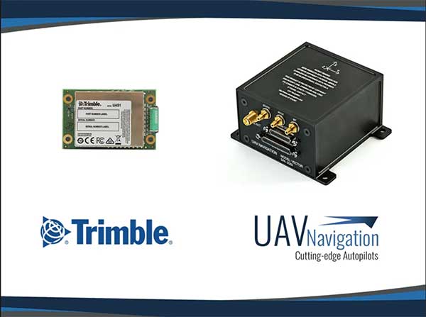
UAV Navigation’s flight control solutions for remotely piloted air systems/unmanned aerial vehicles (RPAS/UAVs) are compatible with the Trimble UAS1 high-precision GNSS receiver. The core benefits of Trimble’s GNSS solution include centimeter-level precision and easy integration.
Image: UAV Navigation and Trimble
The light, small Trimble UAS1 receiver is less vulnerable to vibrations or temperature fluctuations, making it suitable for UAVs and RPAS. In addition, the receiver can provide real-time kinematic (RTK) positioning using a base station, enabling users to achieve higher precision for their projects.
Most UAV missions demand precision in its subsystems. The Trimble UAS1 receiver meets these requirements and includes a 336-channel high-precision GNSS engine. It tracks L1/L2 frequencies from the GPS, GLONASS, Galileo and BeiDou constellations.
The Trimble UAS1 supports OmniSTAR and Trimble CenterPoint RTX GNSS corrections, which enable precise and robust positioning without the use of a base station via a subscription service. The receiver also offers an industry-standard camera hot-shoe interface and a wide DC voltage range to work in a broad range of UAVs.
While Trimble is highly specialized in providing advanced GNSS solutions, UAV Navigation’s focus is on innovations in flight control systems. With this combined technology, current UAV/RPAS systems can now operate in more demanding environments and deliver higher precision through better navigation, UAV Navigation stated in a press release.
Septentrio’s new web shop offers direct access to mosaic multi-frequency GNSS receiver module. Customers can purchase the mosaic development kit quickly and easily to evaluate this unique module.
Septentrio has opened an online store shop.septentrio.com, selling high-performance GPS/GNSS module receivers. The web shop is accessible via the Septentrio website, offering customers multi-constellation multi-frequency GNSS technology, which provides reliable centimeter level positions suitable for demanding applications.
The first product available for sale online is mosaic, Septentrio’s most compact GNSS receiver module. This light-weight, low-power receiver brings robust high-accuracy positioning to the mass market. With its security-centered anti-jamming and anti-spoofing technology, mosaic provides positioning to numerous demanding applications such as automotive ADAS, logistics automation, and robotics.
“We see a growing demand for reliable high-accuracy positioning across various industries. As GNSS receivers move towards becoming a commodity, we are providing our customers with easier and faster access to GNSS technology,” said Francois Freulon, senior product manager, Septentrio. “We are happy to offer the mosaic development kit as the first product in the shop, which makes it easy for people to purchase and evaluate the mosaic module and discover its capabilities for delivering robust, highly-accurate positions. “
True multi-frequency multi-constellation technology of mosaic ensures access to every possible signal from all available GNSS constellations including the U.S. GPS, European Galileo, Russian GLONASS, Chinese BeiDou and Japanese QZSS satellites. Septentrio’s advanced field-proven algorithms exploit this signal diversity to deliver maximum positioning availability even in the most difficult environments such as under foliage or in urban areas.
GNSS signals can become jammed by nearby electronics or illegal jammers that emit radio signals interfering with GNSS. Mosaic uses jamming-resistant signal processing making it robust against interference. Its design focuses on continuous, reliable high-accuracy positioning making mosaic suitable for demanding applications such as ADAS, UAVs and industrial automation.
Drone service slated to begin February 2020, with goals of enhancing efficacy, reliability and predictability of delivering medical products between hospitals and laboratories.
In February, the University of California (UC) San Diego Health will launch a pilot project to test the use of unmanned aerial vehicles to transport medical samples, supplies and documents between Jacobs Medical Center, Moores Cancer Center and the Center for Advanced Laboratory Medicine (CALM), speeding delivery of services and patient care currently managed through ground transport.
Trained professionals will load and operate the drones, which will follow predetermined, low-risk flight paths and will carry no cameras. (Photo: UC San Diego Health)
The program is a collaboration with UPS, which received in September 2019 the Federal Aviation Administration’s (FAA) Part 135 Standard certification and authorization to use unmanned aircraft systems for a drone delivery program, and Matternet, a Mountain View, California-based drone systems developer for health care institutions. This latest effort builds upon the UPS and Matternet drone project already taking place at WakeMed Health and Hospitals, a private, non-profit health care system based in Raleigh, N.C.
“Currently, medical samples that must be transported between health care sites are carried by courier cars, which are naturally subject to the variabilities of traffic and other ground issues,” said Matthew Jenusaitis, chief administrative officer for innovation and transformation at UC San Diego Health. “With drones, we want to demonstrate proof-of-concept for getting vital samples where they need to be for testing or assessment more quickly and simply. It’s another way to leverage emerging technologies in a way that can tangibly benefit our patients.”
The project calls for medical professionals at Jacobs Medical Center, located on the east health campus of UC San Diego in La Jolla, to pack payloads, such as blood samples or documents, into a secure container that attaches to one of Matternet’s M2 rechargeable battery-powered drones.
The drones will follow predetermined, low-risk flight paths, initially between Jacobs Medical Center and special landing sites at Moores Cancer Center, located less than a mile away and within visual line of sight under the FAA’s Part 107 rules, and then subsequently at CALM, which is near the Jacobs Medical Center. The flights will take only minutes to complete and will be monitored by remote operators. The drones will carry no cameras.
In May 2018, the FAA designated the city of San Diego as one of nine lead participants in the regulators’ Integration Pilot Program. UC San Diego was also approved by the FAA to test the use of drones in transporting lab specimens and pharmaceuticals throughout its health system.
“Right now, most biological samples must travel between sites by courier car, within designated hours,” said James Killeen, MD, clinical professor of emergency medicine and director of information technology services at UC San Diego School of Medicine. “That leaves the system vulnerable to the vagaries of road congestion, accidents, construction and more. Travel time can be slow and unpredictable. A drone can fly over such obstacles in a much more direct way, and take just a few minutes to cover the same distance.”
Vexcel Imaging, a provider of aerial imagery data, large-format aerial cameras and photogrammetry software, has signed a definitive agreement to acquire the imagery sourcing group from Verisk’s Geomni business.
The acquisition will combine Geomni’s imagery surveying and content-related teams and assets into Vexcel. Verisk, a data analytics provider, will be a minority owner in Vexcel with full access to all aerial imagery libraries.
The combination of Geomni’s fleet of fixed-wing aircraft and aerial operations, mapping business and oblique aerial image library together with Vexcel’s sensor business and data program will create a world-leading geospatial data library.
Geomni’s analytics team and assets will remain part of Verisk and continue to focus on world-class advanced analytics. The team will work closely with Vexcel on a strategic road map and joint projects.
“The strategic alliance between Vexcel and Verisk demonstrates both companies’ resolve to drive rapid innovation across imagery and analytics — to enter new markets, create new categories, and better serve commercial and insurance customers,” said Jeffrey C. Taylor, president of Geomni. “Partnering with Vexcel is a huge leap forward in the services we can provide customers.”
Vexcel Imaging was founded in 1992. The company’s successful line of UltraCam systems was launched with the first UltraCam in 2003. Vexcel is headquartered in Boulder, Colorado; operates an office in Graz, Austria; and will now have teams and operational hubs strategically located throughout the United States and in Spain.
“Our alliance with Vexcel benefits our customers through a unified, robust, and rapidly expanding global aerial imagery library that will deepen their understanding of ground truth,” said Mark Anquillare, chief operating officer of Verisk. “The combination of Verisk’s and Vexcel’s data will provide tremendous coverage for customers and help drive Verisk’s proven ability to innovate advanced analytic solutions.”
“By combining forces with Verisk, we’re making a progressive move to accelerate innovation within the geospatial data industry,” said Erik Jorgensen, chairman and CEO of Vexcel Imaging. “Vexcel and Verisk share tremendous synergies, and we look forward to bringing the definitive imagery and geospatial data library to the market — unmatched in its size, quality and breadth.”
Vexcel maintains a strong partnership with the Geospatial Intelligence Center (GIC), an insurance industry consortium spearheaded by the National Insurance Crime Bureau (NICB), a nonprofit organization dedicated to fighting insurance fraud and crime, and powered by Vexcel’s data program. The GIC empowers its member insurers to improve their decision making and risk management by leveraging aerial imagery and data in visual tools and automated processes. The partnership will provide enhanced support to GIC member insurers in the form of additional flying and processing capabilities as well as access to the newly scaled and unified geospatial library and enhanced analytics.
The transaction is expected to close the first quarter of this year, subject to the completion of customary closing conditions.
Phase One Industrial, a provider of medium-format metric cameras and imaging solutions for aerial applications, has signed an agreement with AI-Survey GmbH, a developer of UAS survey packages, services and tailor-made solutions.
Together, the companies’ high-end products are opening up opportunities in drone-based high-accuracy mapping and inspection markets, the companies said.
Under this agreement, AI-Survey will support Phase One Industrial’s iXM range of cameras in the UAV market for high-accuracy mapping and inspection. AI-Survey offers fast and efficient, simple and reliable UAS solutions tailored for geodesists with millimetre imaging results.
“Our cameras exemplify AI-Survey’s mission to optimize, increase efficiency and inspire UAV mapping and inspection missions,”said Dov Kalinski, CEO, Phase One Industrial. “As an industry leader, we are confident that they will help our strategic efforts to evolve the industry through innovative solutions using Phase One Industrial technology.”
“We have developed long-term relationships and collaborations with many global technology partners, like Phase One Industrial,” said Carsten Rudolph, managing director, AI-Survey explains. “As an independent solutions provider, with such a large international network at our disposal, we are free to offer the best possible solutions to meet our customer needs and achieve their required accuracies. With Phase One iXM cameras, we now have the best global sensor for UAV mapping available, we believe.”
URISA’s GIS Hall of Fame honors persons and organizations that have made significant and original contributions to the development and application of GIS concepts, tools or resources, or to the GIS profession.
URISA is inviting nominations for 2020 inductees.
Anyone may nominate a person or organization for induction to URISA’s GIS Hall of Fame. To make a nomination, submit a written statement to URISA describing:
The nominee’s achievements, emphasizing significant and original contributions to the development or application of GIS concepts, tools, or resources, or to the GIS profession; and
The significance of the nominee’s contributions, in terms of their enduring impact on the GIS field or profession, and their social benefit.
Hall of Fame laureates are expected to exemplify vision, leadership, perseverance, community-mindedness, professional involvement, and ethical behavior.
Nominations are due on or before May 11. The 2020 URISA GIS Hall of Fame celebration will take place during GIS-Pro 2020 in Baltimore, Maryland.
Visit the URISA website for details about the nominations criteria and process, and to review the path-breaking accomplishments of previous inductees.
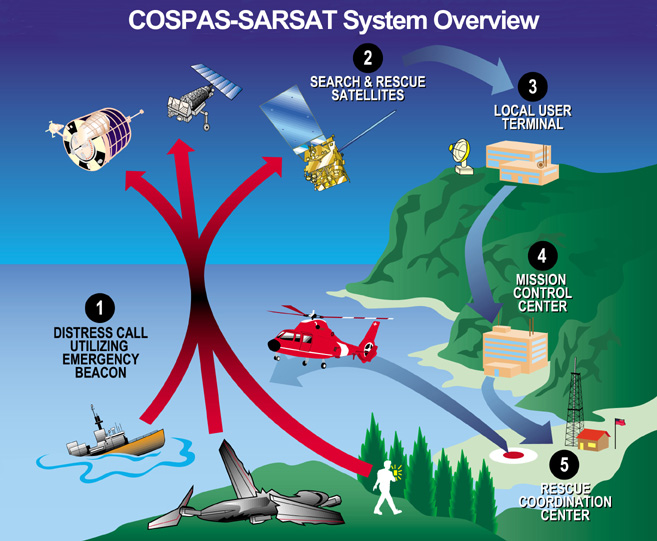
As well as providing global navigation services, Europe’s Galileo satellite constellation is contributing to saving more than 2,000 lives annually by relaying SOS messages to first responders. And from now on the satellites will reply to these messages, assuring people in danger that help is on the way.
This ESA-design return link system, unique to Galileo, was declared operational this week, during the 12th European Space Conference in Belgium. The delivery time for the return link acknowledgement messages from initial emergency beacon activation is expected to be a couple of minutes in the majority of cases, up to 30 minutes maximum, depending primarily on the time it takes to detect and locate the alert.
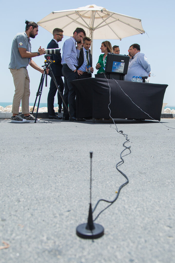
Cospas-Sarsat rescue beacon activated. Its signals are picked up by satellites in orbit, including Galileo. (Photo: GSA)
“Anyone in trouble will now receive solid confirmation, through an indication on their activated beacon, informing them that search and rescue services have been informed of their alert and location,” explains ESA’s Galileo principal search and rescue engineer Igor Stojkovic. “For anyone in a tough situation, such knowledge could make a big difference.”
All but the first two out of 26 Galileo satellites carry a Cospas-Sarsat search and rescue package. At only 8 kg in mass, these life-saving payloads consume just 3 percent of onboard power, with their receive-transmit repeater housed next to the main navigation antenna.
Image: ESA
Founded by Canada, France, Russia and the US in 1979, Cospas-Sarsat began with payloads on low-orbiting satellites, whose rapid orbital motion allows Doppler ranging of distress signals, to pinpoint their location. The drawback is these fly so close to Earth that their field of view is comparatively small.
Geostationary satellites went on to host Cospas-Sarsat payloads. These see much more of the planet, but because they are motionless relative to Earth’s surface, Doppler ranging is not possible.
Medium-orbiting satellites such as Galileo – orbiting at 23 222 km altitude – offer the best of both worlds, providing a wide ground view by multiple satellites combined with time-of-arrival and Doppler ranging techniques to localise SOS signals. This improves the maximum signal detection time from four hours to less than five minutes, down to one or two kilometres (within a formal specification of 5 km within 10 minutes).
Galileo’s Search and Rescue service is Europe’s contribution to Cospas-Sarsat, operated by the European Global Navigation Satellite System Agency, GSA, and designed and developed at ESA. As the overall Galileo system architect and design authority, ESA has been responsible for the interface between the core Galileo infrastructure to the Return Link Service Provider facility, procured by the European Commission and operated by French space agency CNES.
The Cospas-Sarsat satellite repeaters are supplemented by a trio of ground stations at the corners of Europe, known as Medium-Earth Orbit Local User Terminals (MEOLUTs), based in Norway’s Spitsbergen Islands, Cyprus and Spain’s Canary Islands and coordinated from a control centre in Toulouse, France. This trio is soon to become a quartet, with a fourth station on France’s La Reunion Island in the Indian Ocean under development.
The satellites relay distress messages to these MEOLUTs, which then relay them to local search and rescue authorities.
A public demonstration of Galileo’s return link service was performed at the Cospas-Sarsat Joint Committee Meeting in Doha in Qatar in summer 2019. ()Photo: ESA)
The service’s return link message capability was developed as an inherent part of the Galileo system. The messages are relayed to the individual beacons that sent the original distress call by being embedded within Galileo signals broadcast from satellites in their view.
“The switching on of the return link service was enabled by a thorough test campaign carried out by ESA, with the support of the GSA and CNES,” adds Igor. “We needed to be sure the service remains reliable even with multiple distress calls being replied to at once.”
A key milestone was a public demonstration of the return link service, performed at the Cospas-Sarsat Joint Committee Meeting in Doha in Qatar last summer.
“The return link is a joint service of Cospas-Sarsat and Galileo and therefore agreement by Cospas-Sarsat was crucial,” adds Igor.
“This acceptance was achieved through long discussions led by the European Commission at the Cospas-Sarsat Council last November, supported by plentiful documentation of simulations and test results provided by ESA and CNES.”
The development of augmented reality as a tool to manage and visualize hidden infrastructure assets has taken a major step forward following the announcement of a partnership between two technology companies.
MGISS, a U.K. geospatial specialist, has partnered with Canada-based vGIS to transform traditional GIS, BIM and CAD data into stunning augmented-reality visualizations.
Augmented reality provides an interactive experience of an environment where objects that reside in the real world, such as underground pipes, are displayed and enhanced with additional intelligence such as attribute information and maintenance records.
A specialist in the use of geospatial technology in the utility, infrastructure and environment sectors, MGISS said it understands the demands for improved spatial data quality and the requirement to communicate complex, asset dense, 3D environments in an easy-to-consume way.
Photo: MGISS
By combining authoritative survey-grade positions and associated data with consumer-grade hardware MGISS enables users of vGIS to access augmented reality visualizations from any suitable smart device.
vGIS is the leading augmented and mixed reality visualization technology for GIS data. Using the vGIS system, field personnel can see an augmented view that includes holographic infrastructure objects, improving environmental assessments and increasing situational awareness.
“Initiatives such as digital twinning and the expectation of ‘business as usual’ operations require the capture and representation of increasing complex real-world environments. Asset owners and operators face a number of challenges and opportunities including the need to improve safety, reduce risk and ensure what lies beneath our feet meets future infrastructure needs,” said Mike Darracott, managing director and founder of MGISS.
“vGIS truly understand the needs and the challenges facing these sectors. In fact, vGIS goes further than any other Augmented Reality solution by providing a full range of 3D spatial data capabilities; all within a platform that works with existing enterprise systems and data structures,” added Darracott.
“Value is often hidden deep within the structure of data. By helping people ‘see’ data in more intuitive ways, they gain new insights and can subsequently do more with that information. That’s been the core operating philosophy of vGIS,” said Alec Pestov, founder and CEO of Canada based vGIS. “To achieve this we are building an ecosystem bringing together top experts to work jointly towards a common goal. MGISS possesses deep expertise in the spatial services and solutions sector and we are looking forward to joining forces to deliver augmented and mixed reality visualizations in the UK.”
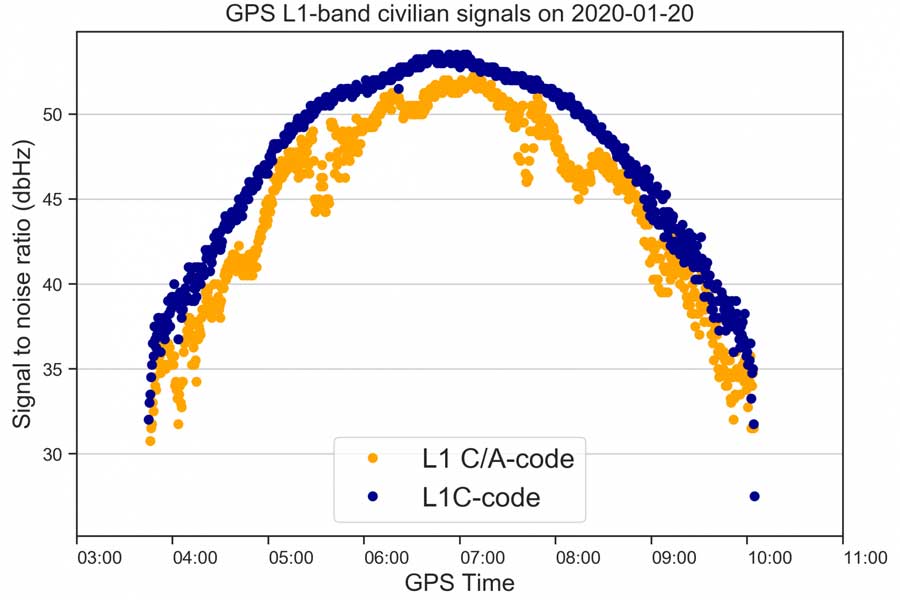
A new GPS civilian signal is now available for use. The new signal is stronger, more accurate, more resilient to interference events, and interoperable with European Galileo system.
On Jan. 13 at 21:29 Finnish time, the first GPS III satellite (SVN74) was marked healthy after extensive operational testing in orbit. The satellite broadcasts PRN04 identification codes. It also transmits a new GPS civilian signal, known as L1C, different than the legacy L1 C/A signal used nowadays.
10 times longer
The two signals are transmitted at the same frequency, but L1C codes are 10 times longer than L1 C/A. This makes the signal more robust to interference when multiple satellites are tracked on the same frequency band.
“Marking a satellite health means receivers can use this satellite in their positioning, navigation and timing applications,” said Octavian Andrei, senior research scientist at the Finnish Geospatial Research Institute (FGI). “L1C is the 4th GPS signal for the civilian use.” The Finnish Geospatial Research Institute is a part of the National Land Survey of Finland.
The other three civilian signals of GPS are L2C, L5 and L1 C/A.
Interoperable with the European GNSS signalL1C signal is transmitted on L1-band at 1575.42 MHz. It is meant to replace the legacy C/A signal in the future. L1C allows for the first time GPS compatibility and full interoperability with signals from other satellite systems, such as E1 signal from the European Galileo.
The interoperability with Galileo is further enhanced by transmission of the inter-system timing biases; that is, the GPS-Galileo Time Offset. All these improvements will bring further benefits and developments to the GNSS market and civilian users in general.
Ionosphere no problem with dual-frequency
Andrei said the new signals means “Exciting times ahead for the civilian users and applications that demand precise satellite positioning and navigation. Most of the effects due to the ionosphere layers of the atmosphere are removed by combining signals from two frequency bands sufficiently apart from each other. This is the case with L1 and L2 or L1 and L5. All these civilian signals are stronger and more robust than ever before,” he explained.
The satellite signals are affected by errors while travelling through the atmosphere. The main errors are due to the ionosphere, which is a dispersive medium and frequency dependent. The latter proves to be actually a significant benefit for the precise applications.
The new signal (L1C, marked with blue) is 3-5 dBHz stronger and more robust than the legacy L1 C/A signal (marked with orange). (Image: Octavian Andrei)
More than 99 % of the ionosphere effect is removed by forming special linear combination of signals observed on two different frequencies. This is the main reason why high-precision is achieved with dual-frequency receivers.
FinnRef network ready for new satellites and signals
“Two GPS III satellites have been launched until now and two more are expected to be launched during 2020. With signals from four satellites, we will also be able to estimate L1C-only positions,” Andrei said.
The first GPS III satellite SVN74, nicknamed Vespucci, was launched on Dec. 23, 2018. The second satellite SVN75, nicknamed Magellan, was launched on Aug.22, 2019. The third and the fourth satellite are planned to be launched in March and July during 2020. The first L1C testing signals were recorded at the FinnRef station in Metsähovi on April 5, 2019.
FinnRef national network includes state-of-the-art multi-constellation tracking stations distributed around Finland. These stations are capable of tracking multiple satellite signals on multiple L-band frequencies from almost 120 GNSS satellites, including the European Union’s Galileo, US GPS, Russian GLONASS, and Chinese BeiDou constellation.
Using new signals often requires updates to station equipment, usually meaning firmware updates on the receiver software. After the new firmware enabling L1C tracking is properly tested, the receivers will be updated and then whole FinnRef will start tracking GPS L1C.
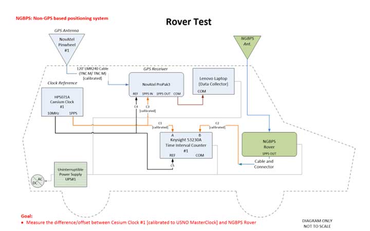
An accuracy test of the Locata Network — a non-GPS-based positioning system installed at the U.S. Air Force White Sands Missile Range in New Mexico — focused on timing down to the nanosecond, with impressive results.
In 2018, the 746th Test Squadron (746 TS) tested its Non-GPS-Based Positioning System (NGBPS) at White Sands Missile Range as an alternative to GNSS for precise time transfer and synchronization. This was the first independently measured and characterized testing program for the NGBPS, which leverages Locata’s radio-based position, navigation and timing (PNT) technology to achieve high accuracy independent of GPS.
Using specific parameters and equipment configurations, independent experts proved Locata’s absolute and relative time synchronization and frequency stability performance. Under testing, the NGBPS provided exceptional time transfer and frequency stability across large areas.
With these successful results in hand, the U.S. Department of Defense will be able to leverage this capability for programs requiring high-precision time and frequency distribution, without relying on GPS alone. Plus, the system is flexible — Locata’s area of transmission can be increased to cover substantially larger areas than at White Sands for safety-of-life, military or government-mandated systems.
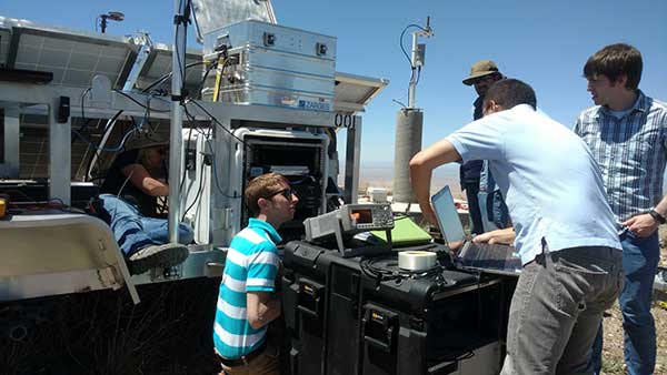
With USNO personnel, members of the 746 TS reconfigure the Master LocataLite site for the test. (Photo: 746 TS/USAF)
Background
Over the past two decades, the free availability of GPS time has enabled a plethora of time-dependent applications. Time and frequency synchronization between remote locations is crucial for digital communication systems, electrical power grids and financial networks, to name a few. Military operations also require accurate and reliable time information. Typically, these applications require accurate time synchronization ranging from 10 microseconds (μs) down to 100 nanoseconds (ns). Yet, while our critical reliance on GPS for time transfer continues to escalate, GPS remains susceptible to interference, disruption or denial.
A technician with the 746 TS re-aims a LocataLite antenna for an alternative TimeLoc configuration. (Photo: 746 TS/USAF)
Locata. Locata Corp., a privately owned Australian company with a U.S. subsidiary, invented a radio-location technology that provides precise PNT for environments where GPS coverage is unavailable. Locata ground-based PNT technology delivers positioning that, in many scenarios, far exceeds the performance and reliability of GPS. LocataNets, the company’s terrestrial networks, function as local ground-based replicas of traditional GPS position and timing services. They can be designed to reliably deliver a powerful, controllable, tailored signal as user applications require.
A LocataNet consists of synchronized LocataLite transceivers, all-in-one units that transmit and receive out of the same 10 x 5 x 1-inch box. Cables are connected to antennas for signal reception and transmission. Locata Rovers are mobile receivers within the network that use these synchronized LocataLite signals to calculate an accurate PNT solution.
The 746 TS employs the basic LocataNet laydown — multiple Slave LocataLites receive signals from a single Master LocataLite transceiver. The patented process by which slaves are synchronized to the master (or other slaves) is known as TimeLoc.
Until these new tests were run, the squadron’s attention had primarily been focused on the high-accuracy use of Locata’s position and navigation solution as an alternative to GPS when it is jammed, deceived or unreliable. But because all LocataLites are precisely synchronized via TimeLoc, network synchronization is a natural extension of Locata technology’s core capabilities.
In October 2015, GPS World reported that the United States Naval Observatory (USNO) showed LocataLites are a viable option for a stable 1 pulse per second (1 pps) distribution setup within an urban environment, where it can support applications such as cell-tower synchronization in GPS-challenged environments. The USNO tests demonstrated synchronization of less than 200 picoseconds — significantly better than any other known wireless network synchronization methodology, including GPS. If clear line-of-sight is available between a master and Slave LocataLite, precision is 50 picoseconds with frequency stability to 1×10-15 —better than a Stratum One atomic clock.
Because of the USNO’s timing expertise and familiarity with Locata TimeLoc testing, the 746 TS tasked the USNO to conduct independent synchronization experiments at White Sands, with the following objectives:
Evaluate the Locata master, slaves and non-Locata timing receiver at the master site in reference to USNO master atomic clock time.
Determine the Locata network’s internal, independent synchronization stability and accuracy.
Determine the Locata Rover’s 1 pulse per second (PPS) time stability and accuracy, for use in time transfer applications.
The primary purpose of the tests was to show that nanosecond-level time transfer is possible over significantly wide areas by using Locata, and that TimeLoc technology offers a relatively easy means of supporting exceptionally high-precision time and frequency distribution over large broadcast areas.
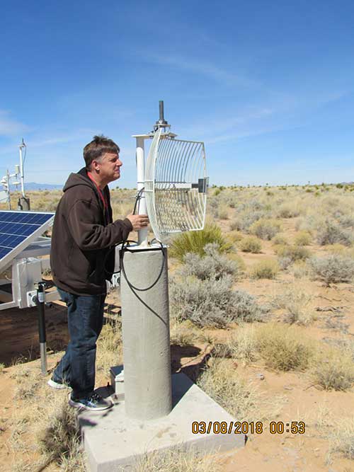
Slave LocataLite site layout. (Photo: 746 TS/USAF)
Synchronization Method
Since Locata technology was originally developed as an RF-based high-precision non-GPS-based positioning and navigation system, the time synchronization accuracy requirements for a LocataLite transceiver are very high. If centimeter positioning precision is desired for a Locata receiver, every small fraction of a second is significant; for instance, a 1-ns error in time equates to an error of approximately 30 centimeters (because of the speed of light).
TimeLoc is a patented high-accuracy wireless synchronization method developed by Locata Corp. It allows LocataLites to achieve high levels of synchronization without atomic clocks, external control cables, differential corrections or a master reference receiver.
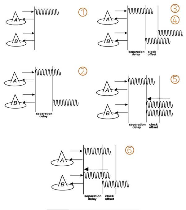
The TimeLoc procedure is described in the following steps for synchronizing two LocataLites (see Figure 1).
LocataLite A transmits a unique signal (code and carrier).
The receiver section of LocataLite B acquires, tracks and measures the signal generated by LocataLite A.
LocataLite B generates its own unique signal (code and carrier) which is transmitted, but, importantly, it is also received by the receiver section of LocataLite B.
LocataLite B calculates the difference between the signal received from LocataLite A and its own locally generated and received unique signal. Ignoring propagation errors, the differences between the two signals are due to the clock difference between the two devices and the geometric separation between them.
LocataLite B adjusts its local oscillator to bring the differences between its own signal and LocataLite A to zero. The signal differences are continually monitored and adjusted so that they remain zero. In other words, the local oscillator of B follows precisely that of A.
The final stage is to correct for the geometrical offset (range) between LocataLite A and B, using the known coordinates of the LocataLites. When this step is accomplished, TimeLoc has been achieved.
Figure 1. The TimeLoc process. (Image: Author)
The only requirement for establishing a LocataNet using TimeLoc is that LocataLites must receive signals from one other LocataLite. However, received signals do not have to come from the same central or Master LocataLite, because this may not be possible in difficult environments or when propagating the LocataNet over large areas. Instead, a LocataNet can “cascade” TimeLoc through intermediate LocataLites. For example, if a third LocataLite C can only receive the signals from B and not Master LocataLite A, it can use B’s signals for time synchronization instead of A’s, provided that B has already TimeLoc’d to the network. Therefore, by using “cascaded TimeLoc,” there is theoretically no limit to the number of LocataLites that can be synchronized.
Test item description
The NGBPS at White Sands consists of an operational LocataNet, where each node (a site instrumented with a LocataLite) is synchronized via Locata’s patented TimeLoc technique. The LocataNet, combined with a mobile Rover, is a subsystem of the 746 TS Ultra-High-Accuracy Reference System (UHARS), which provides PNT information in GPS-denied environments. The NGBPS operates in the 2.4-GHz industrial, scientific and medical band, which is far enough away from GPS frequencies to be unaffected by GPS jamming. Although it is currently used as a source of position truth during GPS jamming, the 746 TS understands that the NGBPS is potentially a source of high-accuracy timing data as well.
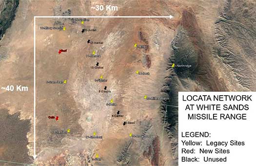
The UHARS is in the northern portion of White Sands Missile Range. It typically consists of 16 LocataLite sites. The master site is at North Oscura Peak, or NOP (labeled Northridge in Figure 2); all other sites are time synchronized to that master site.
Figure 2. Locata network at White Sands Missile Range. (Image: Author)
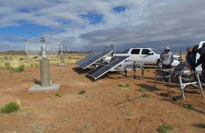
Each LocataLite site consists of:
one LocaLite
two monuments—pillars for antenna placement (Note: The two new sites lack the permanent monuments for antenna placement)
two transmit antennas
one receive antenna
one meteorological station—for meteorological data
one communication antenna
one trailer for power and transport
The communications antenna at each site is attached to a UHF modem that is used for 746 TS remote control of the LocataNet. This allows remote data logging, reconfiguration or monitoring of the network without having to drive to each site. However, it should be noted that no communications system whatsoever is required for the Locata NGBPS TimeLoc capability to run.
To support the timing tests, the LocataNet was reconfigured several times to meet requirements of specific test objectives. These configurations are described below.
Static ground tests
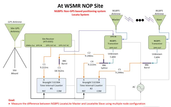
Static ground tests involved multiple configurations. The first (Figure 3) consisted of two LocataLites (master and terminal slave) collocated at NOP close enough that their respective PPS outputs could be compared in a single time interval counter. A terminal Slave LocataLite was installed at NOP specifically for this test.
Figure 3. LocataLite Configuration 1: North Oscura Peak (NOP) site test instrumentation. (Image: Author)
This setup also facilitated simple network reconfiguration to change the number of LocataLite sites being tested. By programming LocataLites to TimeLoc to specific sites at White Sands and redirecting their respective antennas accordingly, the TimeLoc chain under test could be expanded to have multiple sites between the LocataLite master and the collocated terminal slave without changing measuring equipment instrumentation at NOP. This means that the time transfer could hop, or cascade, between one or more sites and be measured with the same test instrumentation.
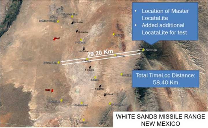
Configuration 2 consisted of three LocataLites: The master at NOP, a slave at Gran-Jean and the terminal slave at NOP. Again, the master and terminal slave were collocated close enough to each other that their respective PPS outputs could be compared in a single time interval counter, but this time the network was configured to cascade the TimeLoc signal through the slave at Gran-Jean, 29.20 km away. Since the TimeLoc signal now had to cascade through two sites and travel from the master at NOP to Gran-Jean and back to the terminal slave at NOP, the effective TimeLoc travel distance was 58.40 km (Figure 4).
Figure 4. LocataLite Configuration 2: Total TimeLoc distance is 58.40 km. (Image: Author)
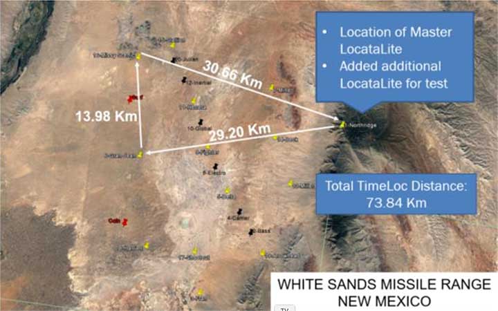
Configuration 3 consisted of four LocataLites: The master at NOP, a slave at Gran-Jean, a slave at Missy-Scenic and the terminal slave at NOP. This configuration forced the TimeLoc signal to cascade through three sites and travel a total distance of 73.84 km (Figure 5).
Figure 5. LocataLite Configuration 3: Total TimeLoc distance is 73.84 km. (Image: Author)
Ground vehicle test
For Configuration 4, a Locata Rover was instrumented on the squadron’s Small Test Vehicle (STV), which drove all accessible roads within the LocataNet’s coverage (Figure 6). During this mobile test, the LocataNet was configured with 10 active LocataLites. The Locata Rover in the vehicle used Locata signals from available nodes to calculate Locata network time, which was synchronized to the GPS timing receiver at NOP. The data collected determined how well network time is synchronized while in a moving vehicle.
Figure 6. Rover test installation on Small Test Vehicle. (Image: Author)
Test results
To collect the required data, USNO first had to characterize the performance of the master site’s GPS timing receiver at NOP, and then synchronize it to two separate USNO atomic clocks that could be used as remote timing references for the tests. The GPS timing receiver is equipped with a rubidium oscillator, which produces a GPS-disciplined 1 pps output signal. Its internal rubidium clock is a stable source of time with an advertised UTC (USNO) offset of a best case 15-ns root mean square (RMS) and a worst case 100-ns RMS.
The cesium clocks output 5- or 10-MHz sinusoids and a 1 pps signal. The cesium clocks output 5- or 10-MHz sinusoids and a 1 pps signal and were characterized relative to the USNO correction receiver, which USNO personnel had characterized relative to UTC. Correction data available from a time interval counter could then be applied to tie the timing receiver back to USNO time. The measurements at NOP recorded the difference between the timing receiver and the cesium clocks. Using the relationship between the cesium clocks and UTC (USNO), one could characterize the timing receiver’s time relative to USNO time.
The USNO calibrated measurements at the nanosecond level using two methodologies. The most common approach was simply to compare two 1 pps signals, a method known as “tick-tick.” Another important methodology is referred to as a “tick-phase,” which is a measurement of a sinusoidal signal compared to a 1 pps reference. Some timing equipment will have discrete time jumps with certain tick-phase measurements, because of how narrow the distance between the rising edges of a sine wave is compared to a 1 pps signal.
There’s a chance that the 1 pps signal is close to two rising edges of a sine wave, causing the signal to jump back and forth in its timing measurement, depending on which rising edge of the sine wave it uses.
Measurements were further complicated by the delicate nature of cesium clocks, which perform best under finely controlled laboratory conditions. Each cesium reference exhibits its own characteristics that must be observed, measured, and accounted for. Moreover, transporting them to White Sands Missile Range for this test where temperature fluctuations, moving vehicle vibrations, and altitude variations among devices were introduced made synchronization of these clocks particularly challenging. For example, USNO discovered that the Cesium Clock #1 had its internal batteries disconnected — possibly through the original shipment to White Sands, the constant vehicle vibrations while driving on the range, a faulty wiring in the battery terminals, or possibly a combination of all. This problem induced a random offset in the clock, and calibration had to be re-accomplished to reestablish traceability back to UTC (USNO).
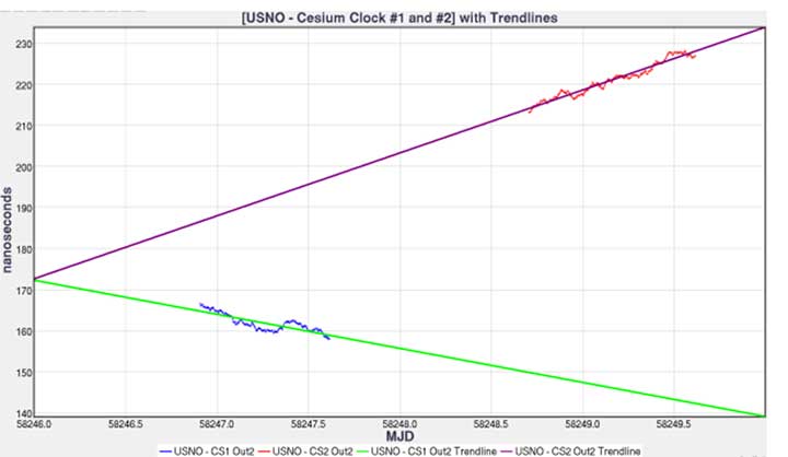
Figure 7 shows each cesium clock’s measured drift rate in nanoseconds/second and its corresponding linear fit. This trendline can then be used to project cesium clock #2 to the past and compare it to the measurements of cesium clock #1.
Figure 7. USNO cesium clocks with trendlines. (Image: Author)
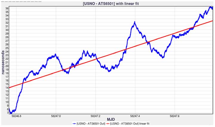
Figure 8 shows the relationship between the timing receiver and USNO master clock and its linear fit. Performing linear fit approximations of the cesium clocks likely introduced unknown errors, potentially increasing the variance of the 1 pps differences.
Figure 8. USNO versus timing receiver with linear fit. (Image: Author)
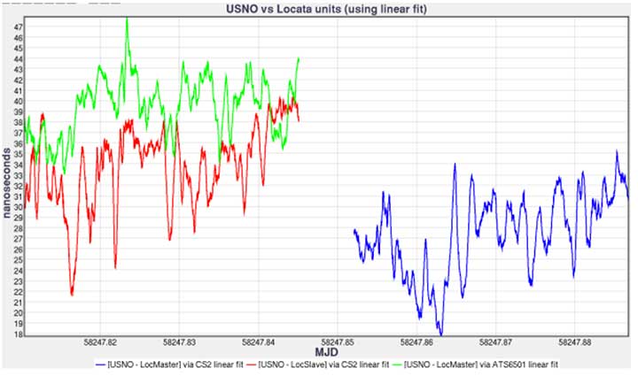
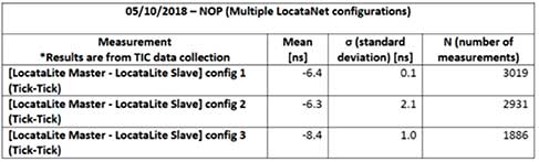
Comparing the 1 pps outputs of the LocataLite master and collocated LocataLite slave to the master site reference clocks (CS2 or timing receiver 1 pps out), the data is traceable back to USNO using the linear fits found for both the USNO timing receiver and cesium clock #2 (Figure 9).
Figure 9. USNO compared to Locata system for May 9, 2018, time interval counter measurements. (Image: Author)
LocataLite timing measurement bias was within 40 ns, and the stability was within 3.7 ns of the reference clocks (see Table 1). The stability of the system is encouraging, as the mean offset can be driven down by more precise measurements and more precise calibrations such as using a two-way satellite time-transfer calibration method (TWSTT).
Table 1. USNO compared to Locata system tabulated values and statistics. (Image: Author)
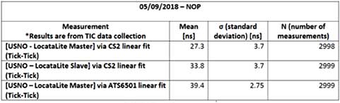
In Table 2, we compare measured data of the 1 pps outputs of the LocataLite master to the collocated LocataLite slave and compute the Locata network internal synchronization in each of the network configurations tested. The data reveals that the network synchronization accuracy is ≤ 2.1 ns. Unfortunately, during Configuration 2 testing, which propagated the TimeLoc signal from NOP to Gran-Jean and back (a total distance of 58.40 km), a technician inadvertently obstructed line-of-site between Locata antennas and consequently temporarily disturbed TimeLoc. Those data points were not removed before this analysis, which is why the reported standard deviation in that configuration, although quite good at 2.1 ns, is nevertheless uncharacteristically high.
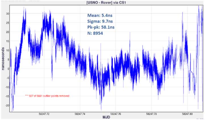
Finally, Figure 10 shows the timing measurements between the USNO master clock and the mobile Locata Rover, via the cesium clock #1 linear fit. Unlike in the LocataLite tests, the Rover is not TimeLoc’d to the network. Instead, it simply calculates its time from LocataLite signals within its line of sight, similar to how a GPS device will calculate its time from satellite signals. During this test, the Rover’s calculated timing accuracy showed a mean of 5.4 ns and stability within 9.7 ns of the USNO master clock, while driving all over the northern portion of the range. To produce the plot, 927 outliers were removed (3 sigma). The outliers occurred at the beginning and ending of the test, when the vehicle was moving from its parking location at Stallion Range Center (outside the operational LocataNet) to the test route and back. The buildings in the area obstructed line of sight and induced significant multipath, which degraded the Rover’s calculations.
Figure 10. USNO LocataLite Rover via CS1 linear fit. (Image: Author)
Conclusion
This endeavor for USNO to characterize the 746 TS NGBPS was met with many challenges, which emphasize the real-world difficulty of measuring time at these extremely fine levels in the field using atomic clocks. The USNO found that some non-linearity started occurring in the USNO – Cesium Clock #2 measurements because of the container of Cesium Clock #2 not being ideal for temperature stability. They also discovered that Cesium Clock #1 had its internal batteries disconnected due to an unknown cause. However, because of deliberate measurements between Cesium Clock #1 and Cesium Clock #2, the USNO was still able to provide calibration measurements but with degradation in the measurement clarity.
From the data collected, USNO personnel found:
The GPS timing receiver at NOP produced 1 pps timing accuracy consistent with its 15-ns RMS specification. Therefore, the reference time delivered to the Master LocataLite was synchronized to UTC within 15 ns.
A standard deviation measurement from Master LocataLite to UTC of under 4 ns.
Locata’s master-to-slave internal time synchronization (independent of GPS) was measured to be between 100 ps and 2.1 ns in 3 different Locata network configurations spanning distances up to 73.84 km (45.88 miles).
The timing measurements in the mobile Rover test show its ability to provide accurate time with a standard deviation of around 10 ns.
Many lessons learned throughout this experiment could be implemented to get more accurate measurements, especially when looking at the accuracies of the GPS time transfer throughout the NGBPS. Looking ahead, more accurate calibration values for both the GPS timing receiver and the Master LocataLite could be made by using a TWSTT method. This would simplify the number of measurements and provide a 1 pps signal of USNO’s master clock, resulting in up to 1 ns of accuracy in the reference time delivered to the Master LocataLite. Depending on the requirements of customers needing NGBPS time at White Sands, the 746 TS and USNO can potentially recharacterize the NGBPS timing accuracy and stability using this methodology.
Manufacturers
The LocataLites and Rovers that create much of the 746 TS NGBPS are manufactured by Locata Corp. The NGBPS synchronized to GPS time via a Microsemi ATS6501 timing receiver. The cesium clocks were Hewlett-Packard 5071A cesium primary frequency standard devices. The USNO used a Novatel ProPak3 for correction data, measured using a Keysight 53230A time interval counter.
Christopher Black earned a B.S. and M.S. in electrical and computer engineering from New Mexico State University. In November 2017 he joined the 746th Test Squadron, Holloman Air Force Base, as a navigation warfare analyst. Now, as lead reference engineer, he heads up research, development and maintenance of the squadron’s reference systems, including UHARS.
This article has been approved by the USAF for public release, #AEDC2019-205.
Carlson Software has released its Scan2K Laser Scanner, a versatile, fast, easy-to-use solution for the creation of accurate 3D survey data up to a range of 2K (2,000) meters. Carlson introduced the product at the Pennsylvania Society of Land Surveyors’ 2020 Conference.
Carlson’s Bradley Husack, Special Projects Engineer, and Michael Hyman, Regional Director with the Scan2K at the Pennsylvania Society of Land Surveyors’ conference. (Photo: Carlson)
Built with surveyors in mind, the Scan2K is at home in the field with its weather-proof housing, user-friendly sunlight-visible touch screen interface with simple, menu-driven operations for quickly collecting and georeferencing point cloud data. With an integrated high-resolution camera, inclinometers, a compass, and an L1 GNSS receiver, the Scan2K can be deployed in many environments and orientations, including mobile operations.
Carlson’s partner on the Scan2K project is Teledyne Optech, a world leader in 3D survey systems. Carlson will be the exclusive global distributor of the OEM Scan2K solution.
“The Scan2K addresses the diverse range of applications for a laser scanner in the surveying and mining industries,” said Bradley Husack, a Special Projects Engineer at Carlson. “Carlson is bringing to market an all-in-one solution that now leads the market in versatility, speed, and value.”
The Carlson Scan2K has a simple, sunlight-visible touchscreen interface. (Photo: Carlson)
Beyond its impressive 2,000 meter range, the Scan2K also has short- and medium-range modes, as well as the capability to record over 500,000 points per second, all within the chosen scanning target window.
Additionally, each laser pulse from the Scan2K records up to four returns, providing the capability to record the first return for a blocking object (such as a leaf) as well as the last return for an object behind it (such as a wall), and the versatility to exclude one or the other.
The Carlson Scan2K comes bundled with ATLAScan software, a powerful yet simple solution for registering the point cloud, as well as Carlson Point Cloud Advanced for feature extraction into Carlson’s suite of CAD office products.
The Scan2K comes ready to be equipped with an additional external camera, an external GNSS receiver, or for mobile operation.
Whether on a tripod, a vehicle, or another moving platform, the performance offered by the Scan2K easily makes it a versatile terrestrial laser scanner for the market.
Verified photomontages for UNESCO World Heritage sites achieves accuracy with Spectra Geospatial SP80
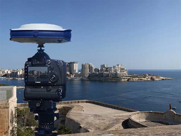
Verified photomontage is an important planning tool to envision how proposed surrounding development plans would affect UNESCO World Heritage sites. Verified photomontage demands the best accuracy for the best visualization to determine what a development may look like to a person standing at the photographic viewpoint.
For MS Environmental (MSE), selected to provide verified photomontage for multiple UNESCO World Heritage sites, including in the UK Royal Botanical Gardens at Kew and the City of Bath, the Spectra Geospatial SP80 GNSS receiver enabled the highest quality visualization.
“The one-centimeter accuracy delivered by the SP80 is essential,” said Mike Spence, a verified photomontage specialist and founder of MSE. “The highest level of accuracy in the relationship between the actual camera location and the 3D model camera gives confidence in the visualization. In addition, The SP80 offers both simplicity and a robust design though it’s taken a few knocks over the years, it gives us the confidence we can use the equipment anywhere in the world and get the best results.”
At Kew Gardens, MSE was commissioned to produce accurate visualizations of views from within the UNESCO World Heritage Site. There was concern about development proposals for tall tower blocks in west London and how these might affect historic views from Kew Gardens.
The work culminated in a public inquiry, where evidence was presented that showed how views would change as a result of the proposed development. “Without the level of accuracy provided by the SP80 together with a transparent technical methodology it would have been unclear precisely how these historic views would change,” Mike Spence said.
At the UNESCO World Heritage City of Bath, the Bath and North East Somerset Council commissioned MSE to produce technical photography from strategic views around the World Heritage City to show how development proposals would affect strategic views across the city.