Author: GPS World Staff

  • A Scintillating Project

    A Scintillating Project

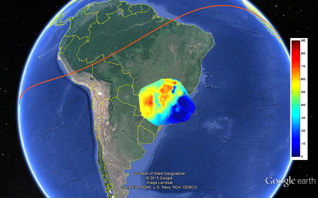
    FIGURE 2. TEC map over São Paulo state as forecast by the CALIBRA model on Sept. 26, 2012, at 2:00 UT. The range of the TEC in the image is from 0 to 90 TEC units (blue to red). The red line is the geomagnetic equator.
    FIGURE 2. TEC map over São Paulo state as forecast by the CALIBRA model on Sept. 26, 2012,
    at 2:00 UT. The range of the TEC in the image is from 0 to 90 TEC units (blue to red). The red
    line is the geomagnetic equator.

    Countering Ionospheric Disturbances Affecting GNSS in Brazil

    By Marcio Aquino

    After 27 months of intense research, the CALIBRA project ended successfully in February 2015, with the project team devising solutions to tackle the effects of perturbations typical of the Brazilian ionosphere on high-accuracy GNSS positioning. CALIBRA was funded by the European Union and the European GNSS Agency.

    Kicked off in 2012, CALIBRA first confirmed the vulnerability of GNSS high-accuracy techniques to ionospheric disturbances through a thorough user performance review, where degradation in GNSS Precise Point Positioning (PPP) and real-time kinematic (RTK) positioning was seen to correlate with the occurrence of ionospheric scintillation and high Total Electron Content (TEC) variability. This is especially so in Brazil, because of its geographical location extending across the magnetic equator in one of the most troublesome ionospheric regions of the Earth, qualifying the country as a test-bed for worst-case scenarios.

    The team established a suitable metric to characterize these disturbances, which was used in developing the new models and algorithms to counter their effects. The short-term empirical CALIBRA Forecasting Model (CFM) for TEC and scintillation was developed and tested.

    To counter scintillation, a number of approaches were proposed and their benefits demonstrated. Building on the project’s success, CALIBRA partner INGV (Istituto Nazionale di Geofisica e Vulcanologia) filed a patent for the CFM and a new spin-off company — SpacEarth Technology — was set up. SpacEarth aims to secure the software’s commercialization for potential applications and services, while also improving and adapting it to evolving market needs.

    Another outcome of commercial interest is that project partner Septentrio developed several rover-level mitigation approaches, notably a new model for ionospheric delay estimation.

    Monitoring Network. To support the research and operational activities of the project, a dedicated network of ionospheric scintillation monitor receivers (ISMRs) was deployed, forming the CIGALA-CALIBRA network of 12 monitoring stations equipped with PolaRxS receivers. A web interface for data analysis — the ISMR Query Tool  — was developed by project partner UNESP (São Paulo State University) and is available for public use, collecting and treating more than 10 million observations of GPS, GLONASS, Galileo, BeiDou and other augmentation systems on a daily basis. Data visualization and data mining techniques support users in data analysis and knowledge extraction.

    Finally, two important field trials aiming to validate the new algorithms were carried out in Brazil, involving actual precision agriculture and offshore operations. For the precision agriculture trial, the Brazilian company Agro Pastoril Campanelli provided expert operational environment and support.

     The tractor used in the precision agriculture trial at Agro Pastoril Campanelli’s premises.
    The tractor used in the precision agriculture trial at Agro Pastoril Campanelli’s premises.

    For the offshore trial, the project counted on the collaboration of the DOF Brasil Group representing Norskan Offshore, a provider of high-end offshore services to the Brazilian oil and gas industry. Detailed results of both trials are in the project’s final report, which can be accessed through the GSA.

    The Geograph vessel is operated by DOF Brasil.
    The Geograph vessel is operated by DOF Brasil.
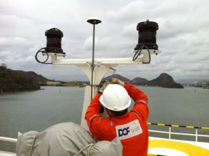
    Setting up the receiver antenna for the offshore trial on board the Geograph vessel.
    Setting up the receiver antenna for the offshore trial on board the Geograph vessel.

    To provide a glimpse of the performance of the CALIBRA algorithms during the offshore trial, in FIGURE 1 we selected a period when strong scintillation conditions were encountered. In the top plot, two height component time series for kinematic PPP processing are shown, respectively, for the case where no mitigation is applied (black time series) and the case where the CALIBRA algorithm is applied (red time series).
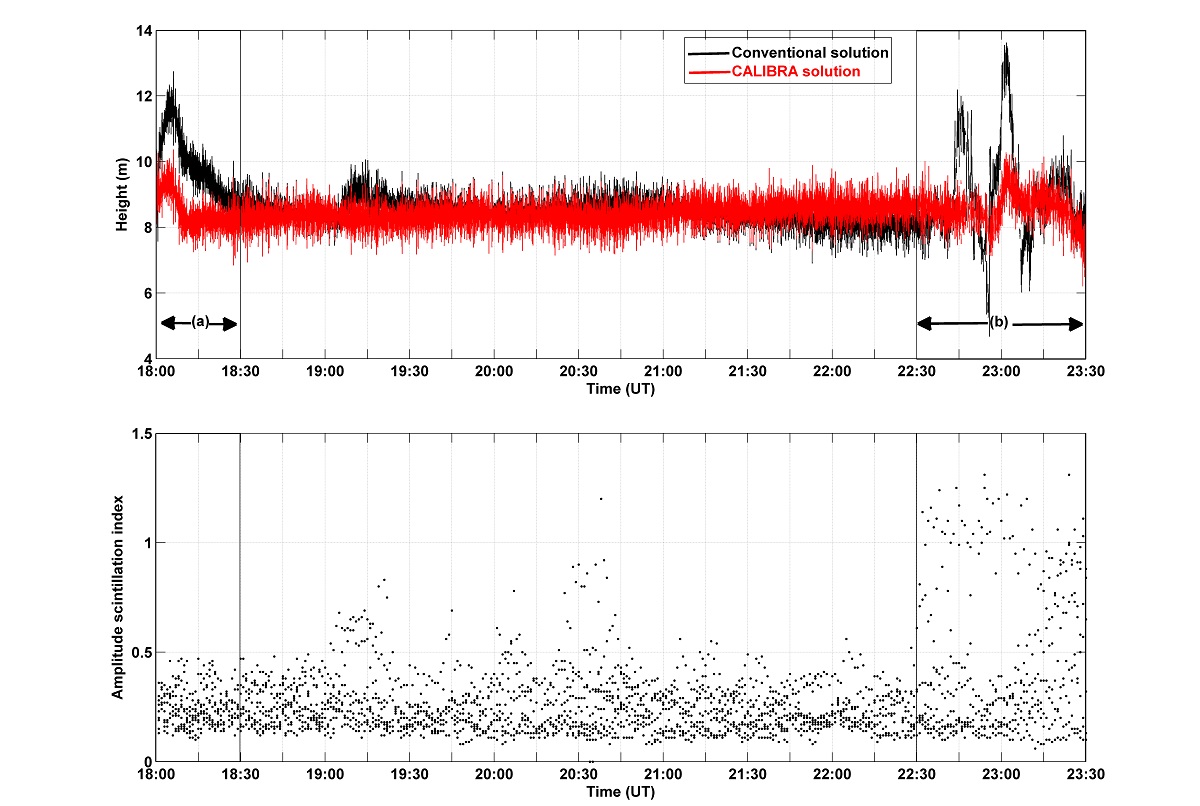
    FIGURE 1. Performance of CALIBRA algorithms in the offshore trial.
    FIGURE 1. Performance of CALIBRA algorithms in the offshore trial.

    The bottom plot shows the level of amplitude scintillation (S4 index) affecting the GPS satellites over a 10-degree elevation angle.

    The improvement obtained with the CALIBRA solution can be seen in particular during the PPP convergence period (18:00 to 18:30 UT) and during the period of strong scintillation (22:30 to 23:30 UT). As there was no accurate ground truth available, the RMS values with respect to the mean height, taken from the quiet period (between 19:00 and 22:00 UTC), along with the percentage of improvement when applying the CALIBRA mitigation approach are summarized in TABLE 1.

    TABLE 1. RMS values with respect to mean height, 19:00–22:00 UTC.
    TABLE 1. RMS values with respect to mean height, 19:00–22:00 UTC.

    Despite all the successful work carried out by CALIBRA, the team notes that research must be continued to accomplish further improvement in models and algorithms to finally develop processes for real-time operation. The challenge would be to counter these ionospheric threats in the scope of an operational service aimed to provide robust high-accuracy positioning to support user applications.

    Furthermore, there were strong indications that the addition of Galileo will assist in mitigating the problems addressed in the project when more signals are available in space.


    Marcio Aquino is a Principal Research Fellow at the Nottingham Geospatial Institute of Nottingham University and leader of CALIBRA.

  • Antenova Launches Sinica Embedded Antenna for GNSS Devices

    Antenova Launches Sinica Embedded Antenna for GNSS Devices

    Antenova logoAntenova Ltd., manufacturer of antennas and RF antenna modules for M2M and the Internet of Things, has announced a new embedded GNSS antenna named Sinica, which operates on the 1559-1609 MHz satellite bands. The Sinica antenna uses a novel design approach and new materials to achieve high performance from an ultra low-profile antenna, Antenova said.

    Sinica is suitable for all positioning applications on the 1559-1609 MHz bands. It operates with all of the public satellite constellations — GPS, GLONASS, Baidou and Gallileo — which means it can provide accurate positioning combined with global coverage.

    The Sinica antenna is created from FR4 materials and new dielectric constant laminate substrates. It uses a new approach to antenna design, which has enabled the company to create an antenna with the high performance of a ceramic patch antenna, in a low profile part that can be placed neatly within a small printed circuit board, Antenova said.

    Sinica is designed for devices that need accurate positioning or tracking globally, which means it is suitable to use in drones, network devices and wearable electronics, or any other portable device or tracking application.

    Antenova’s product designers recently introduced the concept of “Design For Integration” (DFI), which considers how the antenna will operate when it is embedded with a manufacturer’s product. Antenova’s antennas are used within a customer’s design, so they are designed to provide superior RF performance from within the device, and to make the integration of the RF elements easier for the designer, the company said. In addition to this, Antenova provides its customers with technical support during the design, integration and testing phases.

    Earlier this year, Antenova announced three new families of antennas for the fast growing M2M, wireless and IoT sectors. Sinica belongs to the lamiiANT family of new antennas for these market sectors.

    The antennas are supplied on tape and reel and are available through distributors worldwide. Go to www.antenova-m2m.com for more details, or to request an evaluation board for the Sinica antenna.

  • Sentry Stands on Jammer Alert

    Sentry Stands on Jammer Alert

    By Jeffrey Coffed and Joseph Rolli, Harris

    The first and best step to combat the growing worldwide problem of GPS jamming is to pursue technologies that can detect and locate the jammers. Signal Sentry 1000 uses arrayed sensors to do just that: look out for jamming and track down its source once sensed.

    An array of sensors can be deployed for sensitive and high value entities such as infrastructure installations, including airports, railroads, chemical plants, electric power plants and grids, cargo ports, wireless communication systems and financial transfer centers. The sensors will connect to servers that assimilate the sensor data and provide operator interfaces.

    Signal Sentry 1000 is based on a server/client model. The user accesses Signal Sentry using a URL and secure log-in specific to the user’s system. The user’s particular home screen displays a map with each installed sensor displayed with an icon reflecting status. Interferers are displayed as red stars or as error ellipses.

    The Signal Sentry web page lists all the interferers stored in the database with their start and end times. The user can manipulate the list by changing the minimum duration of the event to be displayed as well as if the interferer had been geolocated or not, or both. If an interference event was less than a minute long, it may not have a geolocation entry.

    Geolocation Methodology. Geolocation of jammers is accomplished through proprietary algorithms running at the network server that utilize digitized, timestamped I and Q samples of received interference waveforms, GPS observables, and other parameters captured by each sensor. This data is processed in a Kalman-filter based location algorithm to determine an initial jammer position and track the position of the jammer throughout the jamming event. This improves performance with moving jammers (that is, vehicle-based) and enables continued jammer location with a limited sensor set (potentially due to signal blockage, erroneous data due to multipath, or out-of-range conditions). Upon detection of an interference event by any sensor, the server polls the entire sensor network for data and determines if the information is sufficient to perform geolocation.

    The user receives near-real-time status of event detections and geo-location of the interferer (if possible). Sensor data polling, geolocation processing and GUI updates continue until the interference stops or the emitter goes out of sensor range. Sensor data from each event is stored for later replay and processing using Signal Sentry event analysis tools.

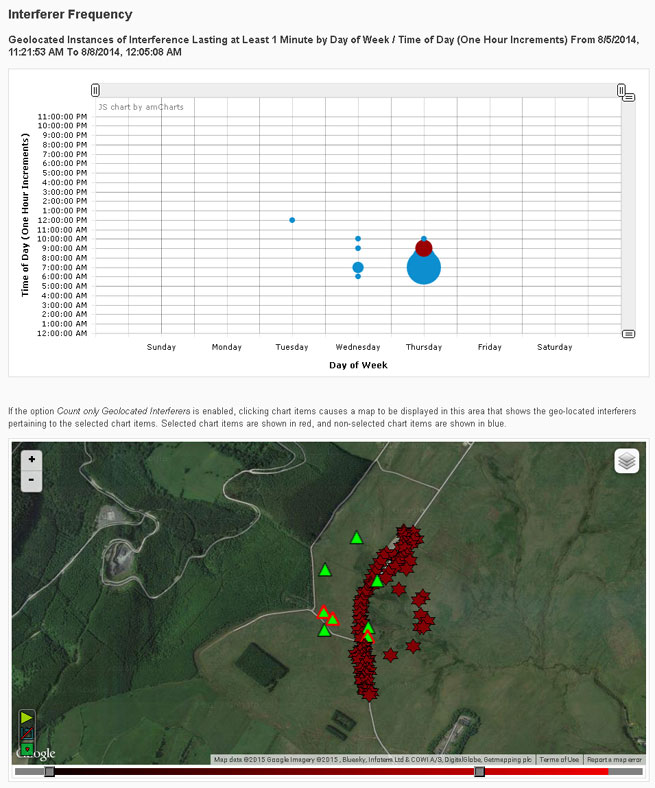
    An interference event frequency chart (Figure 1) provides a tool for forensically evaluating the occurrence of interferers. It displays interference events as circles; the size of the circle represents the number of events that occurred at that day of the week and time. When dots are selected on the chart, a map below the chart shows the location of the interference events. More than one dot can be selected at a time. This allows a user to find correlations in time and space, to determine if events occur at specific locations at certain times of the day and/or days of the week.

    FIGURE 1. Interference event frequency chart.
    FIGURE 1. Interference event frequency chart.

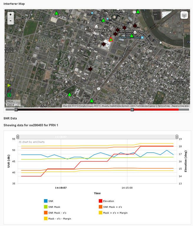
    Selecting the interferer on the map and then the details button on the popup brings up the interferer details page (Figure 2). Users can sign up for interferer alerts to be sent to their email or phone by text.

    FIGURE 2. Interferer details.
    FIGURE 2. Interferer details.

    Testing

    Signal Sentry 1000 was deployed and tested in GPS jamming trials at Sennybridge, United Kingdom, in August 2014. Testing included stationary jammers and mobile jammers moving at up to 50 mph, in open fields and built-up areas.

    Sentry Arrayed. The sensors used in these trials were custom units designed and built to Harris specifications by Chronos Technology Ltd. Each consisted of an embedded GPS receiver, an interference signal receiver and a local processor with a network communications interface.

    An array of eight sensors was geographically distributed around the test facility. Each sensor and a centralized Signal Sentry processing server were equipped with a mesh data networking capable radio for wireless data communications of commands, status and event data. In other Signal Sentry deployments, the server software is typically hosted on a cloud server, and sensors communicate with the server either via hard-wired internet connections or wirelessly through cellphone network-compatible data adapters.

    Jammer Profile. Two jammers performed during the trials, a 150mW and a .5W jammer, used to disrupt the GPS L1 C/A code at 1575.42 MHz.

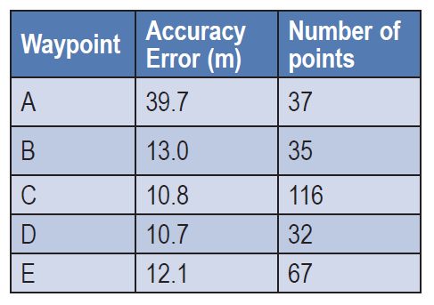
    Open Field. Atest in an area with no obstructions included static jammers and dynamic jammers. Five waypoints along the road, in an area measuring 320 by 444 meters, were surveyed prior to the test using a handheld GPS receiver, to evaluate location accuracy.

    Table 1 shows static test results. The accuracy error is the average delta between the Signal Sentry-reported jammer positions versus the actual surveyed jammer positions. The number of points column contains the number of measurements reported by Signal Sentry during the test scenario for each waypoint. The overall average accuracy error for the static jammer test was 17.25 meters.

    TABLE 1. Open field static accuracy.
    TABLE 1. Open field static accuracy.

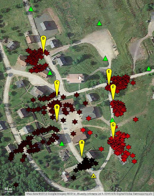
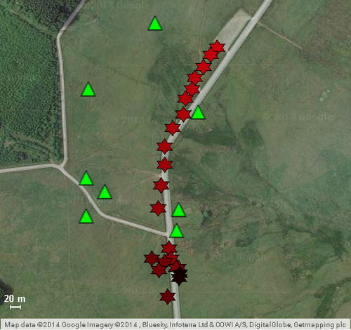
    Open Field, Mobile Jammer. In these tests, the jammer was driven in a car on the road through the sensor field. The car was driven at 25 mph north to south, then 50 mph south to north (Figure 3). Cars in the north parking lot caused multipath errors when the jammer came in contact with that area.The overall average accuracy error for the dynamic tracking was 10 meters.

    FIGURE 3. Jammer locations detected by Signal Sentry, when jammer was driven at 50 miles per hour, north to south. Green triangles denote sensor locations.
    FIGURE 3. Jammer locations detected by
    Signal Sentry, when jammer was driven at
    50 miles per hour, north to south. Green
    triangles denote sensor locations.

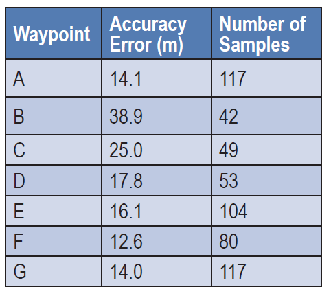
    Obstructed Area Test. This test evaluated performance in an urban environment called a FIBUA (Fighting in Built-up Areas), using stationary and dynamic jammers. Seven waypoints in an area 176m x 253m were surveyed for the purpose of evaluating location accuracy. Table 2 shows the results with the 150mW jammer held stationary at the waypoints. Figure 4 provides a graphical view of the jammer position in relation to the waypoints. The overall average accuracy error is 21.40 meters.

    TABLE 2. Urban static accuracy.
    TABLE 2. Urban static accuracy.

    Obstructed Area, Mobile Jammer. In these tests, the jammer was driven in a car at approximately 20 mph on the road through the sensor field, using a .5W jammer. The overall average accuracy error for this dynamic tracking was 50 meters.

    FIGURE 4. Urban area test; jammer locations in yellow, locations delivered by Signal Sentry in red, sensor locations in green.
    FIGURE 4. Urban area test; jammer locations
    in yellow, locations delivered by Signal
    Sentry in red, sensor locations in green.


    All figures provided by  Jeffrey Coffed and Joseph Rolli.

  • TomTom Selected by University of Minnesota’s Accessibility Observatory

    TomTom’s map and traffic information have been chosen by the University of Minnesota’s Accessibility Observatory as part of a new national accessibility data set.

    TomTom will provide map and historical speed data to help analyze accessibility to jobs for driving and transit for metropolitan areas across the United States. For transit data, the Observatory is relying on open, public sources using a method developed at the University with support from the Center for Transportation Studies.

    Study partners will be able to use this data for policy development, local transportation system evaluation, performance management, planning and research efforts. Each partner will have direct digital access to the accessibility datasets for the jurisdictions of all partners and will receive detailed reports of local accessibility trends and patterns. The Minnesota Department of Transportation is the lead agency and coordinator for the national pooled-fund study. Other participating agencies are the Federal Highway Administration (FHWA) and the DOTs of California, Florida, Iowa, North Carolina, Virginia and Wisconsin.

    “Today’s transportation user wants more than mobility — they want accessibility and they want MnDOT to invest in the appropriate solution, at the right place, at the right time, and at the appropriate cost,” said Tim Henkel, division director of modal planning and program management at MnDOT. “The Accessibility Observatory offers solutions to these decision-making challenges.”

    The Transportation Pooled Fund Program, part of the National Cooperative Highway Research Program, allows state DOTs, FHWA program offices, and other organizations to combine resources and achieve common research goals. Additional partners are welcome to join the study.

    “We’re excited that the UMN Accessibility Observatory has selected TomTom to help provide geospatial and transportation information for this project,” said Ralf-Peter Schäfer, head of traffic at TomTom. “We are confident that the TomTom map and traffic content will contribute to a better understanding of job accessibility nationwide.”

  • A WINS for Warfighters

    A WINS for Warfighters

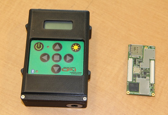
    The current WINS form factor (left) sits beside a prototype for the future incarnation.
    The current WINS form factor (left) sits beside a prototype for the future incarnation.

    The Evolution of the Warfighter Integrated Navigation System

    A new device is being developed to enable foot soldiers to find their exact location in GPS-denied situations. If satellite signals are blocked by heavy jungle canopy, or because of enemy interference, soldiers — and Headquarters — will still know where they are with the Warfighter Integrated Navigation System (WINS).

    WINS will be a compact, wearable navigation device capable of operating either as a standalone system or networked to distribute position location information to other soldier platforms. WINS will extend positioning capability for soldiers in environments where GPS is not available, reducing the effect of GPS interference and enabling integrity monitoring for trusted position reporting.

    The technology behind WINS is being developed at the U.S. Army’s Communications Electronics Research Development and Engineering Center (CERDEC) labs. “WINS will be not just one technology; it’s a soldier-worn multi-sensor source incorporating information from GPS, inertials, vision-aided navigation, RF ranging, etc.,” explained John DelColliano, chief for CERDEC’s PNT Branch, which falls under CERDEC’s Command, Power and Integration Directorate (CP&I).

    “All these will tie in to making a more robust navigation system, so if you’re in a situation where GPS fails, you can have other things to back you up.” For instance, inertial sensors will calculate an offset from the last-known GPS location using footsteps taken, speed, acceleration and time.

    “The bottom line is that the soldier, without having to do any extra work on his own, will have a navigation system on his person that will provide him with a solution that he can count on when he needs it,” DelColliano said.

    WINS is expected to help eliminate dependence on vulnerable commercial receivers. It will improve positioning in GPS-degraded environments, enduring some jamming and providing positioning indoors and in urban areas. It will enable soldier-based cooperative engagements and provide trusted dismounted soldier position through integration with Selective Availability Anti-Spoofing Module (SAASM) GPS receivers and redundant navigation sensors.

    “CP&I’s PNT branch has worked on these individual technologies for many years, but we’ve always had the vision of an integrated solution,” DelColliano said. “That’s where we are today. It makes the most sense for what the soldier is going to need in the battlefield.” With a WINS-equipped solder, DelColliano said, “We’ll be able to know where he is and at what time, and we’ll be able to track if something happened to him. This capability will also enable our forces to be more mobile and maneuverable. It allows the commander and HQ to see where each squad is.”

    As part of a technology demonstration program at Fort Dix, N.J., WINS is being developed under an incremental build process as researchers consider what functionality should be incorporated. The engineering specifications for WINS are expected to be transferred to Program Executive Office, Intelligence and Electronic Warfare & Sensors by 2017, and from there eventually be made available to soldiers.

    Future WINS capabilities

    The final version of the WINS will have the following capabilities:

    • Military GPS for a protected signal and anti-jam capability on the soldier.
    • Inertial measurement unit for soldiers to track their location.
    • RF ranging using a radio or radio-like device to communicate between soldier-worn nodes and determine the range between soldiers, computing positions through triangulation relative to GPS.
    • Vision-aided navigation using the same kind of camera as in a cell phone, which is ideal for SWaP-C (size, weight and power compliance), to help navigate by tracking the soldier’s motion through an environment.
    • Network-assisted navigation and GPS.
    • Chip-scale atomic clock.
  • TomTom Expands Map Footprint Globally

    TomTom has added navigable maps for 13 new countries. TomTom’s global map database now covers more than 45.6 million kilometers and 4.3 billion people worldwide, and features full navigable coverage for 134 countries.

    “The addition of nearly 3 million kilometers of roads in one year demonstrates TomTom’s commitment to geo-expansion,” said Charles Cautley, managing director of TomTom Maps. “We rely on intelligent mapmaking and our transactional mapmaking engine to continuously deliver map updates around the globe, increasing coverage and improving map features for all business customers.”

    Global map enhancements include:

    • The launch of navigable, turn-by-turn maps for Macedonia, Bosnia & Herzegovina, Peru, Guatemala, Nicarágua, Panamá, Costa Rica, Honduras, El Salvador, Iraq, Ghana, Rwanda and Burundi.
    • Introduction of Address Points to enable better geocoding and navigation in Austria, Luxemburg, Turkey and South Africa; significant growth in Address Point coverage for South East Asia reaching 3.6 million.
    • Significant Points of Interest growth in Mexico, bringing count to more than 3 million.
    • Launch of 3D Map for Singapore and the debut of visualization products for the Middle East, with an Advanced City Model of Riyadh and 2D City Maps for 15 cities.
  • Drones Meet Guns — Now What?

    A Kentucky man shot down a drone when it crossed into “his airspace” over his backyard, and was subsequently arrested and charged with criminal mischief and wanton endangerment.

    William Merideth told Ars Technia that he never would have shot the drone with Number 8 birdshot if it had only been flying past. But since it hovered, he felt it was an invasion of privacy. He claims the drone was flying 10 feet above his property and had been spying on his neighbor’s sunbathing daughter.

    “It was just right there,” he told Ars. “It was hovering, I would never have shot it if it was flying. When he came down with a video camera right over my back deck, that’s not going to work. I know they’re neat little vehicles, but one of those uses shouldn’t be flying into people’s yards and videotaping.”

    Merideth’s claims are disputed by the drone’s owner, who has evidence that rebuts Merideth. David Boggs, who was flying the drone, showed WDRB-TV a video of the flight path of the altitude of the drone, showing that the drone did not drop as low as 10 feet. Boggs, one of four owners of $1,800 drone, confronted Merideth and called police. Boggs told WDRB that he bought the drone just a few days before it was shot down and planned on using it to shoot video of his children riding motocross.

    “I would just like [the drone owner] to get some education on his toy and learn to respect the rights of the people,” Merideth said. “It’s fine and dandy, and I think it’s cool there’s a camera on it, but just take it to a park or something — he’s not a responsible drone owner.”

    In another incident involving drones and guns, an 18-year-old mechanical engineering student attached a semi-automatic gun to a quadcopter drone, and posted the result on YouTube in early July.

    The video has been viewed more than 3 million times and was covered by the national media. The Federal Aviation Administration is investigating.

    Peter Sachs, an attorney and drone advocate, welcomes the FAA investigation into the armed drone. “Drones should be used for good, not for evil,” Sachs said. “There are countless ways that drones can be useful. Using one as a remote-controlled weapon is not one of them, and I question the judgment of anyone who would attempt to do so.”

  • Raytheon Installs First GPS OCX Hardware

    Raytheon has installed the first operational hardware for the GPS Next Generation Operational Control System, known as GPS OCX. The new ground command and control system will significantly modernize U.S. GPS capabilities and manage the next generation of GPS satellites. Installation of the Launch and Checkout System (LCS) hardware was completed in early July at Schriever Air Force Base in Colorado, the eventual home for the new GPS OCX Master Control Station.

    “Installation of the initial OCX hardware at Schriever AFB represents a key milestone for the program, demonstrating further progress toward next year’s acceptance of the OCX Launch and Checkout System for the GPS III satellites,” said Matt Gilligan, vice president of Navigation and Environmental Solutions at Raytheon Intelligence, Information and Services.  “Raytheon is committed to delivering a modernized, secure GPS ground system to support the millions of U.S. military, civil and commercial users of GPS worldwide,” added Gilligan.

    GPS OCX will deliver a host of new capabilities, including automation for operational efficiencies, improved accuracy, interoperability with geo-positioning and navigation systems of other nations for better global coverage, and a cybersecurity architecture that provides unprecedented levels of protection. The Launch and Checkout System delivers a large subset of the full OCX ground system capabilities, and establishes the OCX cyber-hardened infrastructure for additional mission applications that will be added to complete the Block 1 capability.

    U.S. warfighters use GPS services to support air, land, sea and space missions. GPS is also used by millions of people to enhance daily life activities, including personal navigation. It’s also required for industry and businesses and is essential to support safety-of-life missions for air traffic controllers and emergency responders. The modernized ground system will bring new capabilities and precision to the GPS enterprise.

  • CSR Acquisition by Qualcomm Finalized with Name Change

    Qualcomm_CSR_acquisition_logos-TCSR is becoming Qualcomm Technologies International.

    Qualcomm started the acquisition process for CSR in October 2014. With the expected close of the acquisition in two weeks on Aug. 13, the name of the company — Cambridge Silicon Radio Limited, or CSR — will be changed to Qualcomm Technologies International Ltd. (QTIL).

    Here is the renamed company’s contact information:

    Qualcomm Technologies International, Ltd.
    Churchill House, Cambridge Business Park, Cowley Road
    Cambridge, CB4 0WZ, UK

    Emails will retain an @csr.com address until a QTIL address is created.

    CSR is known to the GPS/GNSS industry as the maker of the SiRFstar series of chips, which are used in many consumer devices. Qualcomm is a leading maker of chips used in smartphones.

    CSR issued a letter to its customers explaining the change, sent by Chris Dale, senior manager, CSR Global Procurement. Dale asked that customers make the appropriate change in their purchase order systems before Aug. 13.  “As part of an ongoing program of review and improvement to trading arrangements and business processes, we will be updating our standard terms of purchase. You will be able to review the revised terms at qualcomm.com/procurement.”

    The revised terms of purchase will apply to purchase orders issued by QTIL on and after Aug. 13.” Finally, please note that for the near term there will be no changes to the Accounts Payable or purchasing process or contacts,” Dale wrote.

  • Form Factor and Portability of Triumph LS: As High as Your Pole Can Reach

    By  Matt Sibole

    I follow the surveyor connect message board and have seen some general discussion of the form factor of the Javad Triumph LS. I wanted to go into a little more detail on the form factor and portability of a couple of the receivers in the Javad GNSS lineup.

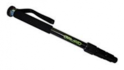
    Most surveyors that have been using RTK GPS equipment have been trained to keep their rod height at 2 meters to reduce error in rod height adjustment and to be able to get above general multipath hardships. This is not required with the Javad Triumph LS. The advanced multipath reduction of the Triumph LS gives the surveyor the flexibility to have the receiver anywhere from just over 1-foot high to as high as your pole may reach. The Triumph LS comes standard with a collapsible monopod pictured here.

    Photo: Triumph LS

    With the Triumph LS being an advanced GNSS receiver and data-collection system all in one, you may ask. “But what if I have to raise the pole above an obstruction to get a shot?” The Triumph LS is equipped with an audible tone and time-delayed shot setting, an internal level, an internal compass and a flashing LED light on the bottom of the receiver that all work together to allow the surveyor to collect points on objects with the receiver high above the surveyor’s head (out of sight). The LS is also equipped with a proximity sensor that will allow you to take a shot even if you cannot reach the receiver’s screen. For instance, you are out in a swamp and you can reach out and get the pole generally level (with internal tilt compensation turned on), but you cannot reach up and start collecting the shot. Wave your hand or a lath in front of the LS, and it will start recording your shot. So no matter your height or the height of the obstructions, you can still get the shot that you need.

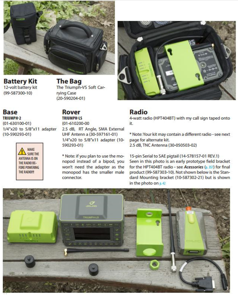
    The form factor of the LS, while it is much different than what we are used to using, works extremely well. The LS rover paired with a Triumph 2 base is one of the most portable systems on the market as well. The Triumph LS, Triumph 2, 4-watt external UHF radio and UHF power cable all fit into a small camera bag.

    Photo: Javad

    This is the system that I personally use on a regular basis. I find that the ability to collapse the monopod allows me to easily use both hands while riding on a four-wheeler along with the ability to easily pack up the system on the four-wheeler to set up the base in more remote locations. With nearly two years of using this system, the form factor has not once been an issue. Quite the contrary — the form factor makes it much easier to navigate dense brush and have more control over the equipment.

    For more information on Javad’s J-Field software, the Triumph LS or other Javad GNSS solutions, please feel free to visit www.javad.com, email [email protected] or call 1-888-550-5301 or 1-408-770-1770.


  • Steep Questions: How Tall is K2?

    A Mountaineering Survey Team Determines K2’s Actual Height

    Surveying the world’s highest peaks is a daunting task. One international survey team set out to measure the Himalaya’s K2 peak, the second highest in the world after Mount Everest.

    In 2004, 50 years after an Italian team led by Ardito Desio first summited, a team tried to measure K2 with GNSS surveying equipment, but the attempt to bring the GNSS receiver to the top failed when a climber fell.

    For the most recent attempt, a Pakasti-Italian team took along a rugged industrial survey system 60 years after the first summiting, in June–August 2014.

    The team performed measurements at five different climbing campsites and on the K2 summit, using GNSS technology to collect the most accurate measurements ever made of K2.

    The measurements were accomplished by Pakistan’s Rehmat Ullah Baigh and Italy’s Michele Cucchi, who set up the receiver at each stop and allowed it to remain for approximately 20 minutes to collect the latitude, longitude and altitude of each point from the available satellites.

    Setting up camp also meant setting up a GNSS receiver to gather data.
    Setting up camp also meant setting up a GNSS receiver to gather
    data.

    One reference receiver was permanently positioned by team technical leader Maurizio Gallo close to the K2 Base Camp at the Gilkey Puchot Memorial, which is dedicated to climbers who died on K2. A second reference receiver was placed in Skardu, a final stop before heading up the mountains. At Skardu, computer expert Fida Hassain from Central Karakorum National Park helped install and process the transmitted data along with researcher Aamir Asghar and Giorgio Poretti, professor at the University of Trieste. The coordinated network of two permanent GNSS stations allowed data from the summit to be processed with excellent precision and is still in operation today.

    After the climb, the data was downloaded from the receivers and analyzed. The GNSS survey results lowered K2’s height from its previous altitude of 8,610.34 meters (28,248.03 feet) to 8,609.02 meters (28,244.75 feet) — 1.5 meters (3.3 feet) shorter than previously believed.

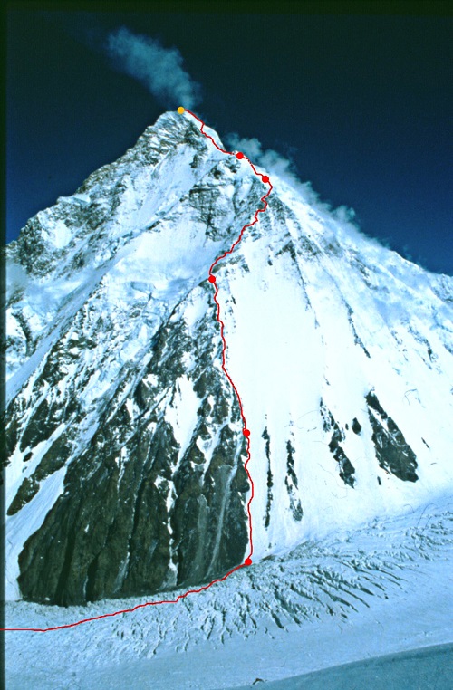
    The route to K2’s summit.
    The route to K2’s summit.

    Yet the biggest surprise was at K2’s Camp Four on the Abruzzi Spur, where expeditions on this route begin their final ascent to the summit. Previous measurements stated that the route began at 7,900 meters (25,920 feet). The new data collected proves that the route starts at 7,747.029 meters (25,416.667 feet), making the climb 150 meters (492 feet) longer than previously recorded. This is a challenging difference for K2 climbers, who at this point are struggling for weeks with the weakening effects of altitude sickness
    and the stress of staying focused.

    The team also plans to climb Mount Everest, where a reference station is located very close to the EVK2CNR’s Pyramid International Laboratory on the Nepali side of Mount Everest.

    Manufacturer

    The survey team used the Leica Viva GS14 GNSS receiver and two GX1230+ reference receivers and antennae provided by Leica Geosystems. Leica Geosystems used the opportunity to test its equipment’s portability, resistance to very low temperatures and rugged use on rough tracks.

    Adapted from an article by Katherine Lehmuller and Marco Mozzon in the Reporter (#72), the Leica Geosystems customer magazine, and other sources.
  • Amazon Delivery Drone Plans Include Tiered Flight Zones

    Amazon has announced a plan for its package-delivery drones, according to NBC News.

    The proposal includes tiered flight zones that would limit small unmanned aircraft systems (sUAS) to slow speeds in airspace below 200 feet and allow them to fly faster for long-distance travel between 200 and 400 feet.


    Commercial aircraft are governed by the Federal Aviation Administration’s (FAA’s) Air Traffic Control, and in Amazon’s vision, there would be a similar central command and control network that takes in data about the position of each drone and shares it with every other vehicle connected to the network. The command and control network would also have vehicle-to-vehicle communication, similar to networks proposed for autonomous automobiles.

    Amazon’s plan would be to use the space below 500 feet — minus a 100-foot buffer — for small drones such as its Prime Air vehicles.

    Access to the various layers of the airspace would be governed by how well a drone can communicate with its pilot, the command and control network and other drone, according to The Verge website. “Everyone can have access to the airspace,” said Gur Kimchi, who heads up Amazon’s Prime Air program. “It doesn’t matter if you’re a hobbyist or a corporation. If you’ve got the right equipment, you can fly.”

    Someone operating a radio-controlled quadcopter with no Internet connection would be relegated to the area below 200 feet.