Author: GPS World Staff

  • Street Smart: 3D City Mapping and Modeling for Positioning with Multi-GNSS

    Street Smart: 3D City Mapping and Modeling for Positioning with Multi-GNSS

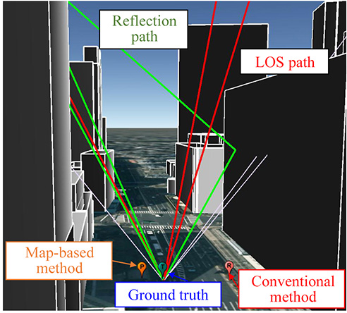
    Figure 1. Example of the GNSS signal propagation using ray-tracing and a 3D building map.
    Figure 1. Example of the GNSS signal propagation using ray-tracing and a 3D building map.

    A particle-filter-based positioning method using a 3D map to rectify the errors created by multipath and non-line-of-sight signals on the positioning result delivered by a low-cost single-frequency GPS receiver takes a multi-GNSS approach, using the combined signals of GPS, GLONASS and QZSS. The method outperforms conventional positioning in availability and positioning accuracy. It will likely be fused with other sensors in a future pedestrian navigation application.

    By Li-Ta Hsu, Shunsuke Miura and Shunsuke Kamijo

    GPS provides an accurate and reliable positioning/timing service for pedestrian application in open field environments. Unfortunately, its positioning performance in urban areas still has a lot of room for  improvement, due to signal blockages and reflections caused by tall buildings. The signal reflections can be divided into multipath and non-line-of-sight (NLOS) effects. Recently, use of 3D building models as aiding information to mitigate or exclude multipath and NLOS effects has become a promising area of study.

    At first, researchers used the 3D map model to simulate multipath effects to assess the single-reflection environment of a city. Subsequently, the metric of NLOS signal exclusion using an elevation-enhanced map, extracted from a 3D map, was developed and tested using real vehicular data. An extended idea of identifying NLOS signals using an infrared camera onboard a vehicle has been suggested. The potential of using a dynamic 3D map to design a multipath-exclusion filter for a vehicle-based tightly coupled GPS/INS integration system has also been studied. A forecast satellite visibility based on a 3D urban model to exclude NLOS signals in urban areas was developed.

    The research approaches outlined above seek to exclude the NLOS signal; however, the exclusion is very likely to cause a horizontal dilution of precision distortion scenario, due to the blockage of buildings along the two sides of streets. In other words, the lateral (cross direction) positioning error would be much larger than that of the along-track direction.

    Therefore, approaches applying multipath and NLOS signals as measurements become essential. One of the most common methods, the shadow-matching method, uses 3D building models to predict satellite visibility and compare it with measured satellite visibility to improve the cross street positioning accuracy. A multipath and NLOS delay estimation based on software-defined radio and a 3D surface model based on a particle filter was proposed and tested in a static experiment in the Shinjuku area of Tokyo.The research team of The University of Tokyo developed a particle-filter-based positioning method using a 3D map to rectify the positioning result of commercial GPS single-frequency receiver for pedestrian applications.

    An evaluation of the QZSS L1-submeter-class augmentation with integrity function (L1-SAIF) correction to the proposed pedestrian positioning method was also discussed in an earlier paper by the authors of this article. However, satellite visibility in the urban canyon using only GPS and QZSS would not be enough for this proposed method. The use of emerging multi-GNSS, encompassing GLONASS, Galileo and BeiDou, could furnish a potential solution to the lack of visible satellites for this method. This article assess the performance of the proposed pedestrian positioning method using GPS, GLONASS and QZSS.

    Building Models Construction

    Our work established a 3D building model by a 2D map that contained building location and height information of buildings from 3D point-clouds data. The Fundamental Geospatial Data (FGD) of Japan, which provided by Japan geospatial information authority, is open to the Japanese public. This FGD data is employed as 2D geographic information system (GIS) data. Thus, the layouts and positions of every building on the map could be obtained from the 2D GIS data. In this article, the 3D digital surface model (DSM) data is provided by Aero Asahi Corporation. Figure 2 shows the process of constructing the 3D building model used here. This process first extracts the coordinates of every building corner from FGD as shown in the left of Figure 2. Then, the 2D map is integrated with the height data from DSM. The right of Figure 2 illustrates an example of a 3D building model established in this way. The 3D building map contains a  very small amount of data for each building in comparison to that of the 3D graphic application. For our purposes, the file only contains the frame data of each building instead of the detail polygons data. This basic 3D building map is utilized in the simulation of ray-tracing.
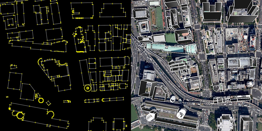
    Figure 2. The construction of the 3D building map from a 2D map and DSM.
    Figure 2. The construction of the 3D building map from a 2D map and DSM.

    Our version of the ray-tracing method does not consider diffractions or multiple reflections because these signals occurred under unfavorable conditions. Here, we utilize only the direct path and a single reflected path. The developed ray-tracing simulation can be used to distinguish reflected rays and to estimate the reflection delay distance. Our research work assumes that the surfaces of buildings are reflective smooth planes, that is, mirrors. Therefore, the rays in the simulation obey the laws of reflection. In the real world, the roughness and the absorption of the reflective surface might create a mismatch between the ray-tracing simulation and the real propagation. Here we ignore this effect, as the roughness of the building surface is much smaller than the propagation distance.

    The opening figure (Figure 1) shows an example of the GNSS signal propagation using ray-tracing and a 3D building map. Red, green and white lines denote the LOS path, reflected paths and the NLOS paths, respectively. In this environment, a conventional positioning method such as weighted least squares (WLS) usually estimates the position on the wrong side of street as shown in the red balloon. With the aid of 3D building model and ray-tracing, the map-based positioning method is able to provide a result close to the ground truth.

    Map-Based Pedestrian Positioning

    The flowchart of the 3D city building model-based particle filter is shown in Figure 3. This method first implements a particle filter to distribute position candidates (particles) around the ground-truth position. In Step 2, when a candidate position is given, the method can evaluate whether each satellite is in LOS, multipath or NLOS by applying the ray-tracing procedure with a 3D building model. According to the signal strength, namely carrier-to-noise ratio (C/N0), the satellite could be roughly classified into LOS, NLOS and multipath scenarios. If the type of signal is consistent between C/N0 and ray-tracing classification, the simulated pseudorange of the satellite for the candidate will be calculated. In the LOS case, simulated pseudoranges can be estimated as the distance of the direct path between the satellite and the assumed position. In the multipath and NLOS cases, simulated pseudoranges can be estimated as the distance of the reflected path between the satellite and the candidate position via the building surface.
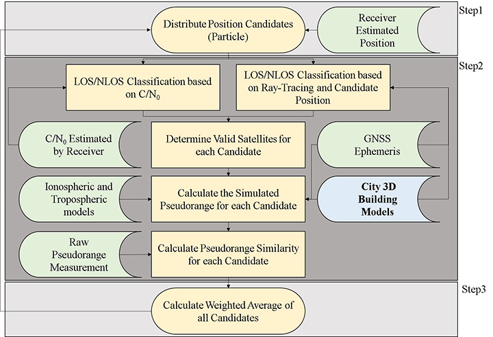
    Figure 3. Flowchart of the particle filter using 3D city building models.
    Figure 3. Flowchart of the particle filter using 3D city building models.

    Ideally, if the position of a candidate is located at the true position, the difference between the simulated and measured pseudoranges should be zero. In other words, the simulated and measured pseudoranges should be identical. Therefore, the likelihood of each valid candidate is evaluated based on the pseudorange difference between the pseudorange measurement and simulated pseudorange of the candidate, which is simulated by 3D building models and ray-tracing.

    Finally, the expectation of all the candidates is the rectified positioning of the proposed map method. This method can therefore find the optimum position through a dedicated optimization algorithm of these assumptions and evaluations. The positioning principle of the proposed method is very different from the conventional GPS positioning method, that is, WLS. As a result, the calculation of the positioning accuracy of the 3D map method should be also different.

    We define two positioning performance measures for the 3D map method: user range accuracy of the 3D map method (URA3Dmap) and positioning accuracy.

    The value of URA3Dmap is to indicate its level of positioning service, which is similar to the user range accuracy (URA) of conventional GPS. The URA3Dmap is defined based on the percentage of the valid candidates from all candidates outside the building. The higher percentage of the valid candidate implies a higher confidence of the estimated position. Ideally, if the center of the candidate distribution is not far from the ground truth, the simulated pseudorange of the candidates located at the center of distribution would be very similar to the measurement pseudorange. We define the URA3Dmap as shown in Table 1.
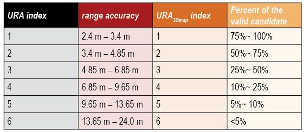
    Table 1. The definition of URA and URA3Dmap used in this article.
    Table 1. The definition of URA and URA3Dmap used in this article.

    Experiments and Discussion

    We selected the Hitotsubashi and Shinjuku areas in Tokyo to construct a 3D building model because of the density of the tall buildings. In this area, multipath and NLOS effect are frequently observed. We tested pedestrian navigation in a typical path that included walking both sides of street and passing through/waiting at a road intersection. The cut-off angle is 20 degrees. The data were collected in November and December 2014.

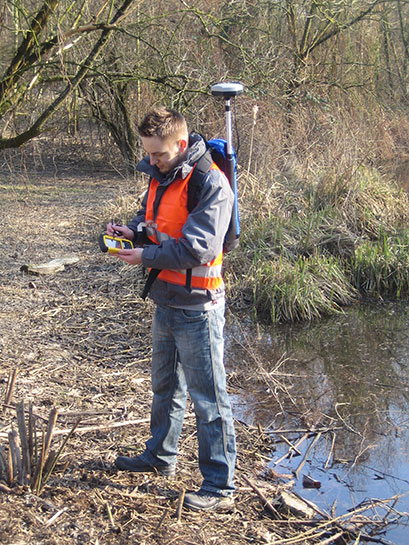
    We compare here two single point positioning methods: single-point positioning solutions provided by open source RTKLIB software (RTKLIB SPP), and the proposed 3D map method. RAIM FDE of the RTKLIB SPP is used here as a conventional NLOS detection algorithm. The test used a geodetic-grade GNSS receiver and a commercial grade receiver. The geodetic receiver was only used to collect the QZSS L1-SAIF correction signal. The antenna of the commercial receiver was attached in the strap of the backpack as shown in Figure 4. The receiver is connected to a tablet to record the GNSS measurements and is set to output pseudorange measurements and positioning results every second.
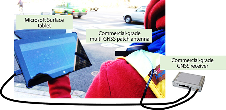
    Figure 4. Equipment set-up.
    Figure 4. Equipment set-up.

    We generated a quasi-ground truth using a topographical method.Video cameras were set in the ninth and18th floors of a building near the Hitotsubashi and Shinjuku areas, respectively, to record the traveled path. The video data output by the cameras are used in combination with one purchased high-resolution aerial photo to get the ground truth data. The aerial photo is 25 cm/pixel and therefore the error distance for each estimate can be calculated. The synchronization between video camera and commercial GNSS receiver is difficult to get as accurate as in the topographical method. As a result, we used point to “points” positioning error to evaluate the performance of the dynamic experiment. The synchronization error is limited to 1 second. Hence, for each estimated position x(t), the ground truth points used to calculate the positioning error is xGT (t-1), xGT (t) and xGT (t+1). The point to “points” positioning error is calculated as:

    Streetsmart-Eq1

    Three performance metrics are used here: mean, standard deviation of the point to points error, and the availability of positioning solution. The availability defined here means the percentage of given solutions in a fixed period. For example, if a method outputs 80 epochs in 100 seconds, the availability of the method is 80 percent.

    This research demonstrates two dynamic data. The skyplot of the data are shown in Figure 5. The satellites are tracked by the commercial receiver. The grey areas indicate the obstruction of the surrounding buildings. The two dynamic data are typical signal receptions at Hitotsubashi (middle urban canyon) and Shinjuku (deep urban canyon) areas.

    Hitotsubashi Mid-Canyon. To study the benefit of using different GNSS constellations in the 3D map method, Figure 6 shows the trajectory estimated by the proposed method under different satellite constellations. The different colors indicate different values of URA3Dmap of each point. This walking trajectory is divided into five sections (identified as A, B, C, D and E in the right-most of the three plots). In the GPS-only case (left), results in A and B sections have much better performance than sections D and E, because more than half of the GPS satellites are blocked at D and E, as shown in the left of Figure 5.
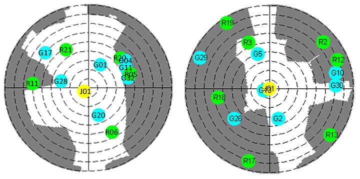
    Figure 5. The left and right are the skyplot of the dynamic experiment at the Hitotsubashi and Shinjuku areas, respectively, in Tokyo.
    Figure 5. The left and right are the skyplot of the dynamic experiment at the Hitotsubashi and Shinjuku areas, respectively, in Tokyo.

    The middle plot in Figure 6 shows the trajectory using GLONASS. It is obvious that the positioning results located at the right side of street are greatly increased, derived from the greater number of satellites in view. However, the quality of the GLONASS signal is not as good as GPS because multipath has a double effect on GLONASS.
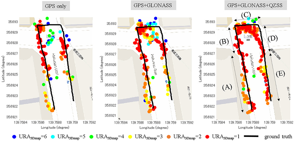
    Figure 6. Positioning results of the proposed 3D map method using different combinations of satellite constellations in a middle urban canyon.
    Figure 6. Positioning results of the proposed 3D map method using different combinations of satellite constellations in a middle urban canyon.

    In summary, the positioning error of applying GLONASS maintains a similar level, and availability increases about 12 percent compared to using GPS only. The right plot of Figure 6 shows the result after adding QZSS L1 C/A and L1-SAIF. This increases the results of C, D and E sections, because QZSS provides a high-elevation-angle satellite to the 3D map method. As a result, the number of valid candidate points in C, D and E sections increases dramatically. The reliability in C, D and E sections is also much higher than that of GPS+GLONASS. In addition, the trajectory became smoother than before.

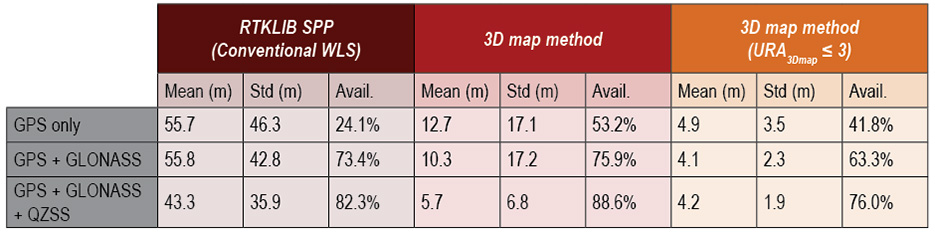
    Table 2 compares the positioning results of both RTKLIB SPP and the 3D map method, showing the 3D map method using GPS, GLONASS and QZSS to have the best performance among three scenarios. The positioning error mean and availability are 3.89 meters and 96.72 percent, respectively. The positioning error mean could be further improved to 3.23 meters if selecting the position point with URA3Dmap ≤ 3 (yellow, orange and red points in Figure 6). This selection will lose about 17 percent of availability.
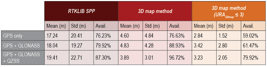
    Table 2. Positioning results of the 3D map method using different combinations of satellite constellations in a middle urban canyon.
    Table 2. Positioning results of the 3D map method using different combinations of satellite constellations in a middle urban canyon.

    Shinjuku Deep Canyon. We conducted a similar experiment in the Shinjuku area of Tokyo, the most urbanized area in Japan (Figure 7). The positioning results and skyplot are shown in Figure 8 and the right of Figure 5, respectively. Table 3 compares the results of the two methods using the three constellation configurations.

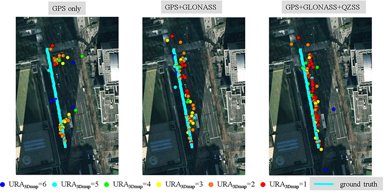
    Figure 7. Deep urban canyon environment, Shinjuku, Tokyo.  (Courtesy Google Earth)
    Figure 7. Deep urban canyon environment, Shinjuku, Tokyo. (Courtesy Google Earth)
    Figure 8. Positioning results of the proposed 3D map method using different combinations of satellite constellations in a deep urban canyon.
    Figure 8. Positioning results of the proposed 3D map method using different combinations of satellite constellations in a deep urban canyon.
    Table 3. Performance comparison of RTKLIB SPP and the proposed 3D map method using different combinations of satellite constellations in a deep urban canyon.
    Table 3. Performance comparison of RTKLIB SPP and the proposed 3D map method using different combinations of satellite constellations in a deep urban canyon.

    As shown in the left of Figure 8, only half of the GPS-only solutions are on the correct side of the street. A few points are incorrect due to the insufficient number of satellites. Adding GLONASS measurements greatly increases the availability, and most of the GPS-only outliers are corrected. The positioning error mean improves from 12.7 to 10.3 meters, and the availability improves from 53.2 to 75.9 percent. GLONASS measurements provide such a significant improvement because the distribution of GPS and GLONASS satellites are complementary.

    After adding the QZSS measurements, availability further increases to 88.6 percent, and positioning error mean is reduced to 5.7 meters. The positioning error mean could be further improved to 4.2 meters if selecting the position points with URA3Dmap ≤ 3: the red, orange and yellow points in Figure 8. Although this selection will lose about 12 percent of availability, it could be easily compensated by a simple filtering technique.

    Comparing Table 2 and Table 3, we find the positioning error of the proposed method in the middle urban canyon is about 1 meter worse than that in the deep urban canyon. This is because of the increase of multiple reflected signals.

    The target application of this 3D map method is consumer-based pedestrian navigation. Most of these applications benefit from an integrated system of multiple sensors. The 3D map method could serve as one sensor for such an integrated system. The calculation of positioning accuracy is required to indicate the quality of the point solution estimated by this method. Figure 9 shows the relationship between the calculated accuracy and positioning error. We can find that the calculated accuracy is able to describe the performance of the proposed method.
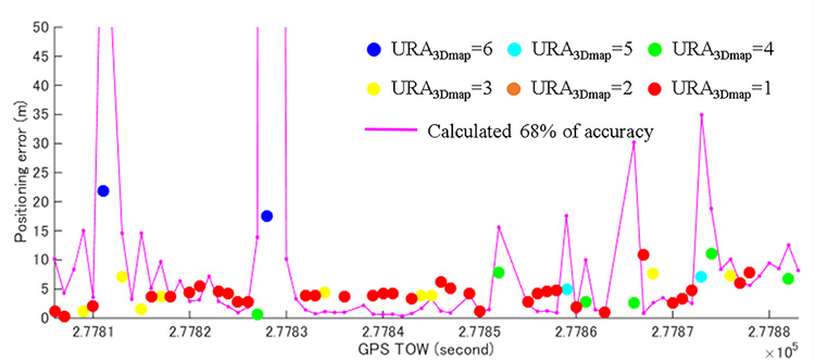
    Figure 9. Positioning error of the 3D map method using GPS+GLONASS+QZSS. The purple line denotes the calculated 68 percent accuracy of the proposed method.
    Figure 9. Positioning error of the 3D map method using GPS+GLONASS+QZSS. The purple line denotes the calculated 68 percent accuracy of the proposed method.

    The performance of the conventional method is very inaccurate in this deep urban canyon. Its positioning error is larger than 40 meters. Figure 10 shows the number of satellites in this data. Note the number of LOS satellites is determined by the ray-tracing simulation according to the ground truth trajectory.
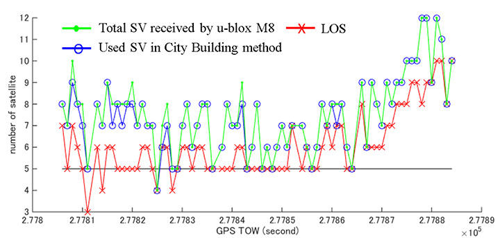
    Figure 10. Number of LOS satellites, the number of satellites used in the 3D map method, and the total number of satellites tracked by the commercial-grade receiver.
    Figure 10. Number of LOS satellites, the number of satellites used in the 3D map method, and the total number of satellites tracked by the commercial-grade receiver.

    The number of LOS satellites means the light-of-sight path of satellite is not blocked by buildings. Note that the LOS signal also contains the multipath effect. In this deep urban canyon, the number of LOS signals is much less than that of all received satellites. This implies a lot of NLOS is received, which deteriorates the performance of the conventional method. The map-based method is able to correct most of the NLOS signals.

    The number of satellites used in the map-based method is close to the number of all the satellites received. Therefore the map-based method can achieve better performance than the conventional method. Figure 11 demonstrates the comparison between the map-based method and the commercial GNSS receiver. The map-based method is simply smoothed by a moving average filter with 3 seconds data. It is difficult to understand the pedestrian trajectory by the commercial-grade receiver result. In some cases, the commercial receiver will estimate the pedestrian to be on the wrong side of the streets. The proposed method, instead, is capable of estimating the result at the correct side of the street.
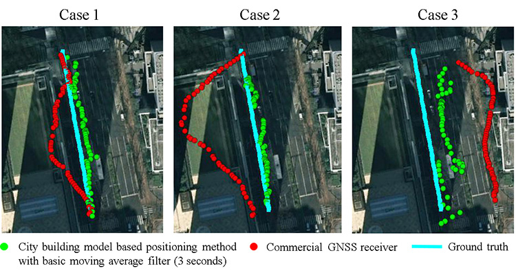
    Figure 11. Positioning results of the proposed 3D map method and commercial-grade receiver using GPS+GLONASS+QZSS in the deep urban canyon.
    Figure 11. Positioning results of the proposed 3D map method and commercial-grade receiver using GPS+GLONASS+QZSS in the deep urban canyon.

    Li-Ta Hsu is a post-doctoral researcher at the Institute of Industrial Science of the University of Tokyo. He received his Ph.D. degree in aeronautics and astronautics from National Cheng Kung University, Taiwan.

    Shunsuke Miura received an M.S. degree in information science from the University of Tokyo in 2013.

    Shunsuke Kamijo received a Ph.D. in information engineering from the University of Tokyo, where he is now an associate professor.

  • Thad Allen Discusses eLoran at GEOINT 2015

    In this exclusive interview, Admiral Thad Allen, former commandant of the U.S. Coast Guard, discusses PNT alternatives to GPS for navigation, including eLoran and the activation June 19 of a signal on an eLoran tower in preparation for a timing signal trial.

    Art Kalinksi interviewed Adm. Allen during GEOINT 2015, held June 22-25 in Washington, D.C. Kalinski is the monthly columnist for Geointelligence Insider, part of the Geospatial Solutions website, a sister site to GPS World magazine.

    Allan is an executive vice president at Booz Allen Hamilton, and a leader in the firm’s Departments of Justice and Homeland Security business in the civil market. In 2010, President Obama selected him to serve as the National Incident Commander for the unified response to the Deepwater Horizon oil spill in the Gulf of Mexico.

  • IS-GNSS 2015 Extends Scholarship Paper Deadline

    Organizers of the International Symposium on GNSS (IS-GNSS 2015) have extended the deadline for submission of the abstracts for scholarship applied papers for one week. The new deadline is July 7 23:59:59 JST (UTC+9).

    The one-week extension was added because organizers are presenting a paper in the Korean Institute on July 1.

    The deadline for submitting abstracts for regular papers remains August 15.

    The IS-GNSS 2015 will be held Nov. 16-19 in Kyoto, Japan. It will bring together experts engaged in PNT and GNSS technologies — including industry professionals, practitioners, academics and researchers — to share their latest research results and allow cross-disciplinary exchange of knowledge to advance the fields.

    The student scholarship will be offered to a student with the most promising paper. “If you have students, please encourage them to apply,” said Akio Yasuda, president of Institute of Positioning, Navigation and Timing of Japan.

    The program will include keynote addresses, oral presentations, interactive poster sessions, panel sessions, open interactive forums and an informative trade exhibition.

    The Asia and Pacific Rim meeting of the CGIC (Civil GPS Service Interface Committee) will be co-located with ISGNSS 2015 to help improve understanding of world trends in developing and deploying GNSS.

    For more information on the conference, including sponsorships and exhibits, email [email protected].

  • Mobile Computing Product Showcase

    Mobile Computing Product Showcase

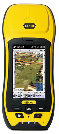
    LT500-CHCNav-landscape-W
    Photo courtesy of CHC Navigation.

    From our July issue comes this showcase featuring products for surveyors, geographic information systems (GIS) professionals, field workers, and anyone who is looking to expand the capabilities of their smartphone or tablet.

    Dedicated Survey/Geospatial

    LT500-with-DigiTerra-WThree-Accuracy Series

    The LT500 series of handheld GPS receivers, LT500H/T/N, covers three accuracy ranges from sub-meter to centimeter. It is a cost-effective full GNSS positioning solution for survey, construction and GIS professionals.

    Powered by the Windows Embedded Handheld 6.5 operating system, the LT500 is accurate, rugged and versatile. User productivity is enhanced with the built-in gyroscope, an innovative laser plummet for positioning the accurate handheld receiver over a point, an E-compass for showing the direction and G-sensors for leveling. The LT500 series comes bundled with software including SurvCE, DigiTerra and MapCloud. The LT500H has120 channels (GPS L1/L2/L2C, GLONASS G1, G2, BeiDou B1 and Galileo E1), the LT500T has 220 channels (L1, G1, B1), and the LT500N has 12 channels (L1).

    CHC Navigation, www.chcnav.com


    GNSS Survey Receiver

    TR-LS-JAVAD-Triumph-WThe all-in-one TRIUMPH-LS by JAVAD GNSS combines a high-performance 864-channel GNSS receiver, all-frequency GNSS antenna, and a modern featured handheld. The 864 all-in-view channels include Galileo E1/E5A/E5B, GPS L1/L2/L5, GLONASS L1/L2/L3, QZSS L1/L2/L5, BeiDou B1/B2 and SBAS L1/L5.

    More than 100 channels are dedicated to continuous interference monitoring, allowing safe GNSS operation in a city, airport and military environment.

    JAVAD GNSS, www.javad.com


    Custom GIS Data Recording

    Geosat-GEOmeter-MX-WThe GEOmeter MX system is designed to gather GIS information in heavily wooded areas, with object description, area coordinates and measurement time grasped automatically. The system consists of the GEOsat MXbox receiver, a combination antenna, a PDA such as the Trimble Recon or the Handheld Nautiz X8, and GEOfield software for mobile GIS.

    The Mxbox receiver is a Hemisphere multi-constellation GNSS OEM board with GPS, GLONASS, BeiDou, Galileo and QZSS, plus code- and carrier-phase tracking for increased positioning accuracy and availability. The GEOfield software offers reliabe recording, representation and processing of geodata. Measurement quality is indicated in the field with statistics and graphics, in either German or English.

    GEOsat GmbH, www.geosat.de


    Software-Defined Radio Platform

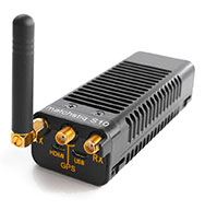
    Epiq-MatchstiqS10-WThe Matchstiq S10 is a software-defined radio (SDR) platform. It provides increased RF flexibility, RF performance and signal processing capacity in a small package. The Matchstiq S10 platform combines the Epiq Solutions’ Sidekiq SDR with a quad-core processor system running Linux. The Sidekiq MiniPCIe SDR card provides an independently tunable RF transmitter and receiver covering 70 Mhz to 6 Ghz with an RF bandwidth up to 50 Mhz, plus FPGA. The Matchstiq S10 platform also integrates GPS, Gigabit ethernet (with PoE), USB 2.0 OTG, HDMI and real-time clock in a very small form factor package.

    Epiq Solutions, www.epiqsolutions.com


    CS35_FRONT_300DPI_RGB-W

    3D Field Capture for GNSS

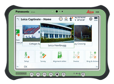
    CS20_FULL_FRONT_300DPI_RGB-WLeica Captivate software provides a 3D view for the Leica Viva GNSS, merging the overlay of measured points, 3D models and point clouds into a single view.

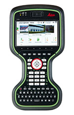
    Using Leica Captivate, users can capture and manage complex data with the touchscreen on both the Leica CS20 handheld controller and the CS35 tablet.

    The CS20 runs on Windows EC7 and is IP68 and MIL-STD-810F rated. It has a 5-inch WVGA color touchscreen that allows for comfortable and quick data processing and a fully integrated radio and antenna for long range robotic total station control. The CS35’s 10.1-inch screen is visible in all conditions. It runs on Windows 8.1 Pro, enabling workers to take their office into the field. It is IP65 and MIL-STD-810G rated.

    Leica Geosystems, www.leica-geosystems.com


    GIS Field Controller

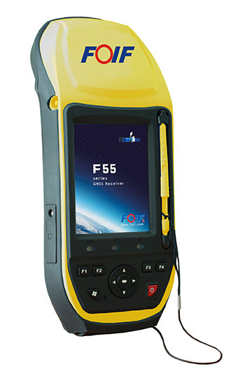
    Foif-F55-WThe FOIF F55 series GIS handheld comes in two models: F55-A and F55-B. The onboard software FOIF SuperGiS allows users to conduct field mapping with powerful functions for data collecting, data editing and data querying.

    The F55 measures 234 x 99 x 56 mm and weighs 895 grams. It has an IP65 rating for water and dust protection. The F55-A supports four GNSS (GPS, GLONASS, Galileo and Beidou) as well as SBAS, and can search for up to 120 channels. The F55-B supports GPS and SBAS and provides 12 channels.

    With Differential GPS, the F55-A has an accuracy of 0.4 meters, and the F55-B has an accuracy of 0.5 meters. RTK surveying on the F55-A obtains high precision of 1 cm + 1 ppm. Real-time correction service and post-processing are available.

    FOIF, www.foif.com


    LVEA-P_Powerline-W

    High-Definition GPS Digital Video Recorder

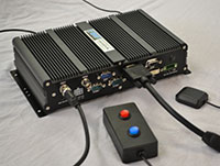
    geoDVR2_2HD2SD-WThe geoDVR Gen2 is an advanced multi-channel high-definition/standard-definition geospatial digital video recorder designed for aerial and mobile environments.

    Unlike a DVR, the rugged geoDVR permanently embeds videos with important GPS location, time and other data — the GPS metadata remains intact even when a video is edited. Most video cameras and gyro-stabilized gimbals can be connected to the geoDVR for recording of HD or geospatial video files.

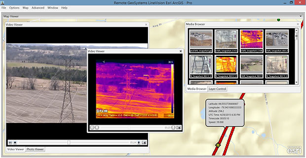
    Video files created by the geoDVR can be analyzed in the RemoteGeo LineVision suite of mapping applications, including tools for Google Earth, Esri ArcGIS, PLS-CADD and the LineVision Cloud. The administrative dashboard allows for monitoring up to four video streams in real-time.

    RemoteGeo, www.remotegeo.com


    Portable Surveying System

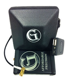
    G1-m1-geomatics-WThe G1-m1 receiver is part of the G1 family of products from Geomatics USA. The G1 system is scalable from a single-frequency semi-mobile receiver — for control networks and some semi-kinematic mapping applications — to a dual-frequency network RTK solution. It was designed to be lightweight, accurate and portable, especially suited to building a system for travel; for example, all the G1-m1 components, including tripod, will easily pack into a baseball-style bag for transport. The G1-m1 offers centimeter and sub-foot accuracy (centimeter-level accuracy is possible for OPUS-compliant static sessions).

    Geomatics USA, www.navtechgps.com


    Mobile Workforce

    Windows Tablet with GPS

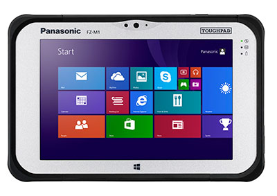
    Panasonic-FZ-M1-WThe Panasonic Toughpad FZ-M1 is a thin, light and rugged 7-inch Windows tablet with dedicated GPS — the u-blox Neo M8 series — as an option. The FZ-M1 is built to enable mission-critical mobile worker productivity. Powered by Windows 8.1 Pro and a choice of two Intel processors, it features a long life, user-replaceable battery and a daylight-readable, high-sensitivity multi touchscreen for use with heavy gloves. With a broad range of configuration options, the customizable Toughpad FZ-M1 is rated MIL-STD-810G and IP65, resistant to five-foot drops, weather, dust and water.

    Panasonic, panasonic.com


    Handheld with Correction Service

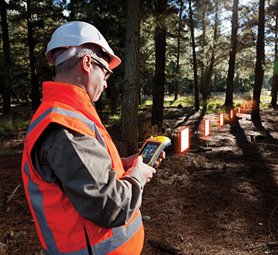
    Trimble-Geo-7X-Forestry-WTrimble’s RTX technology-based correction services — Trimble CenterPoint RTX, Trimble RangePoint RTX and the new Trimble ViewPoint RTX — are now available on Trimble Geo 7X handhelds.

    Trimble RTX technology provides compatible GNSS receivers with correction services that significantly improve accuracy and reliability in obtaining positions worldwide. Operational efficiency and productivity in the field is improved by delivering real-time DGNSS corrections directly to the Trimble Geo 7X handheld.

    The handheld solution is designed for industries such as utility companies, municipalities and environmental management agencies, in which workers are highly mobile and require a reliable, flexible data-collection and asset management solution.

    A choice of RTX correction services ranging from 4 centimeters to submeter-level horizontal accuracies is available.

    Trimble, www.trimble.com


    Smartphone and Tablet Products

    Laser Measurements with Smartphones

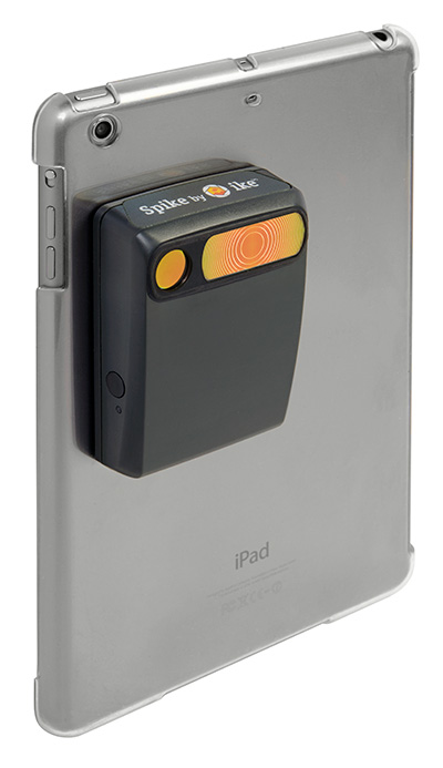
    Spike-with-iPad-Mini-WThe Spike device and Spike mobile app allow users to measure an object by capturing a photo from a smartphone or tablet. From the photo, users can capture real-time measurements, including height, width, area, length and target location. Location data includes latitude, longitude and altitude. Spike is useful for construction, inspection, safety, advertising, real estate, insurance and government applications.

    Measurements and location data are saved with the picture and can be shared via email as a PDF, XML and KMZ. KMZ files can be imported into GIS tools such as ArcGIS and Google Earth. The photo can be referenced via the Spike app to take new measurements or view original measurements.

    The Spike device pairs with an Android or Apple iOS smartphone or tablet via Bluetooth. Its laser rangefinder works with a smartphone’s camera, GPS, compass and Internet connection.

    ikeGPS, www.ikegps.com


    High-Accuracy GNSS Receiver for iPad or iPhone

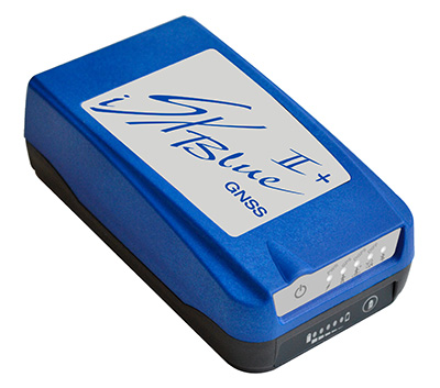
    iSXBII+GNSS-WThe iSXBlue II+ GNSS is a palm-sized receiver that delivers real-time, high-accuracy performance using GPS+GLONASS satellites and free SBAS corrections for an iPad or iPhone. Its battery-powered lightweight design is for a variety of mapping applications including GIS, forestry, mining, utilities, agriculture, surveying and environmental. It delivers high accuracy in real time without the need for post-processing or another correction source when SBAS (WAAS, EGNOS, MSAS or GAGAN) are available. Using both GPS and GLONASS satellites, the iSXBlue II+ GNSS will work where GPS receivers struggle, such as in the forest, around buildings and in other difficult mapping environments. The L1/G1, GPS+GLONASS receiver has 372 channels.

    Geneq, www.sxbluegps.com


    Software for Data Collection

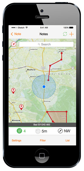
    IPhone_notes_map-TerraGo-WTerraGo Edge allows organizations to collect data and share field information on their smartphones and tablets. TerraGo Edge replaces traditional GPS handheld devices with a mobile cloud-based solution. Users can collect GPS data points at any accuracy level, either by using the onboard GPS on a smartphone or by attaching a centimeter-level GPS receiver to a mobile device.

    TerraGo Edge 3.6 features enhanced support for high-accuracy GPS receivers such as EOS and SXBlue on both iOS and Android, as well as better mapping features, basemap sources and integration with Google Earth.

    For managers, TerraGo Edge provides a real-time dashboard for monitoring field users and data collection.

    TerraGo, terragotech.com


    Smartphone Precision Farming

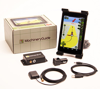
    MachineryGuide-WMachineryGuide enables a tablet or smartphone to be used as a precision tractor GPS system. The MachineryGuide Android guidance program functions as a precision farming application using an antenna capable of receiving and processing EGNOS and WAAS corrections. It can be used for any farming activity that is done by tractor or other agricultural machinery, including fertilization, manure application and spraying. It even can be used for land measurements.

    MachineryGuide sells the software separately; a GNSS receiver + antenna separately; and a package bundle that includes software, GNSS receiver and antenna. The receiver uses GPS, GLONASS, SBAS and QZSS signals for a position accuracy of 2.5 meters CEP.

    MachineryGuide, machineryguideapp.com


    Action Camera and App

    tomtom-bandit-action-camera-WThe TomTom Bandit Action Camera allows creation of videos within moments of the action. It comes with a built-in media server, eliminating the need to download footage before editing. The camera works with a companion app, making it possible to create and share videos in a matter of minutes — by shaking a smartphone.

    The TomTom Bandit Action Camera is equipped with in-camera motion and GPS sensors to automatically find and tag footage based on speed, altitude, G-force, acceleration and heart rate. Highlights can also be tagged manually with a tagging button on the camera or the remote control.

    TomTomwww.tomtom.com


    GPS Running Watch

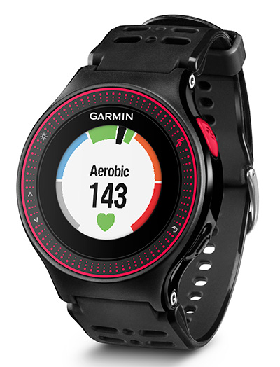
    Forerunner_Garmin-225-WThe Forerunner 225 integrates optical heart-rate technology by Mio and features a colorful graphic interface showing runners their zone and beats per minute at a glance. A built-in accelerometer provides distance and pace data for indoor running with no need for a separate foot pod. To keep runners active between workouts, it doubles as an activity tracker, counting steps, calories and distance.

    When paired with a compatible smartphone, the Forerunner 225 will automatically upload a completed run to the Garmin Connect Mobile app for post-run analysis and sharing on social media sites. Runners can also use live tracking to allow friends and family to follow along during training or on race day to see stats in real time.

    Garmin, www.garmin.com

  • Satel Launches Tiny Radio Data Transceiver

    Satel Launches Tiny Radio Data Transceiver

    Satel presents the tiny UHF radio data transceiver module Satelline TR4.
    Satel presents the tiny UHF radio data transceiver module Satelline TR4.

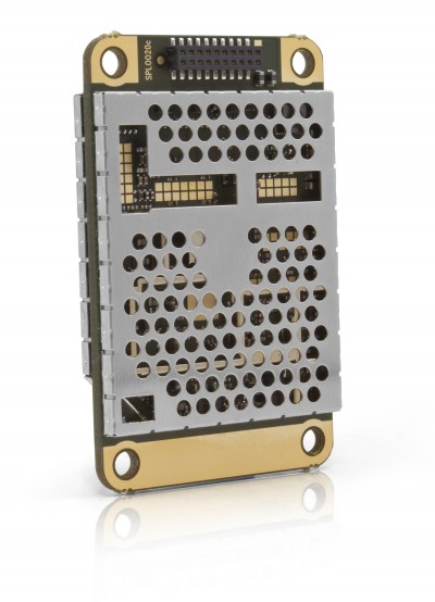
    The new Satelline TR4 from Satel, a Finnish manufacturer of radio data transmission systems, is a compact UHF transceiver with transmitting power of 1,000 mW. The transceiver is compatible with the protocols of Pacific Crest, Trimble and Satel.

    The type certifications in important regions of the world make the TR4 ideal for integration in end devices intended for international use. With a weight of only 18 g, transmitting power of 1,000 mW and an “over the air” data transmission rate of 38,400 bps, it fulfills all present-day standards, Satel said.

    The tiny UHF transceiver is designed for easy integration, with dimensions of 56 x 36 x 6 millimeters, Satel said. Robust UHF frequencies (400-470 MHz) are a reliable basis for the communication of self-sufficient stations even in the event of unknown topology. In addition, the new TR4 features the advantages of the Satelline EASy and 3AS modems, including channel scanning, error correction and compatibility with protocols of Pacific Crest, Trimble and, of course, Satel.

    Since license-free frequencies are becoming more popular, such as 869 MHz in Europe and 915 MHz for the American market, transceiver modules of identical design will follow. The identical footprint and the standardized communication commands will minimize integration costs. Later it will only be necessary to insert the corresponding radio module for the destination and the end device will be ready to use.

    In Germany, radio data transmission solutions from Satel are distributed exclusively by the full-range and systems provider Welotec. At INTERGEO in Stuttgart,  September 15 – 17, the partners will present their products at adjacent stands: Satel and Welotec will be in Hall 4 – Booth G4.020.

  • Garmin Offers Trucking Navigator with Built-in Dash Cam

    Garmin Offers Trucking Navigator with Built-in Dash Cam

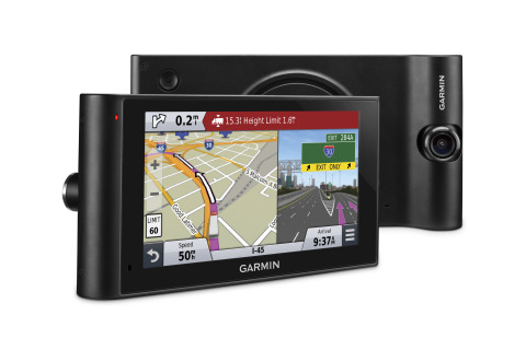
    The Garmin dezlCam trucking navigator has a built-in dash cam.
    The Garmin dezlCam trucking navigator has a built-in dash cam.

    Garmin International Inc. is offering dēzlCam, an all-in-one trucking navigator with a built-in dash cam that serves as an onboard eyewitness. Truckers can rely on firsthand video footage that continually records the drive and automatically saves video footage on impact.

    The dēzlCam provides custom truck routing for the size and weight of a driver’s truck as well as route warnings for bridge heights, weight limits, sharp curves, steep grades and more.

    “The dēzlCam is an innovative navigation solution for truckers,” said Dan Bartel, Garmin vice president of worldwide sales. “As technology evolves, so do the needs of truck drivers who spend their lives on the road. Truckers will like dēzlCam especially because of its premium trucking features combined with an integrated dash cam that records proof of road incidents and protects their driving reputation. The combination of these features adds significant value to our trucking community.”

    This premium truck navigator features a six-inch pinch-to-zoom display, a built-in dash cam with an adjustable swivel lens, and a magnetic mount to quickly secure or remove the dēzlCam from a driver’s truck. The built-in dash cam starts recording as soon as the dēzlCam is powered on, while the Incident Detection (G-sensor) automatically saves footage of collisions upon impact.

    Location, speed, date and time data can be optionally recorded allowing drivers to know precisely when and where an incident occurred. The Snapshot feature captures still images and provides truckers the freedom to remove the dēzlCam from their truck to take close-up pictures. Users can also play back driving footage directly on the device, or review on a computer using garmin.com/dashcamplayer.

    A comprehensive directory of preloaded TruckDown Locations and Services make it easy to find places highly rated by truckers. Drivers can filter trucking points of interest to find locations with their preferred brands or amenities.

    The dēzlCam is also bundled with Foursquare data that adds millions of new and popular points of interest to the navigator’s searchable database. Easy Route Shaping lets drivers modify a route to include preferred cities or roads by touching the screen. The Up Ahead feature displays a constant stream of nearby services, such as upcoming rest areas, fuel stations and restaurants.

    The dēzlCam also provides a history log to record fuel usage, IFTA mileage and hours of service, and displays mile-marker information, automatic time zone changes and alerts drivers of upcoming state and country borders.

    Created with safety in mind, the dēzlCam offers advanced navigation features that aid truckers in reaching their desired destination. Voice-activated navigation lets truckers control the dēzlCam with their voice, while Bluetooth technology allows for hands-free calling and pairing with a Bluetooth-enabled headset (sold separately). The dēzlCam is also compatible with the Garmin BC 30 Wireless Backup Camera (sold separately) to easily see behind a truck when in reverse. Spoken Garmin Real Directions can help drivers locate hard-to-find addresses with spoken directions that use recognizable landmarks, buildings and traffic lights. Active Lane Guidance with helpful voice prompts indicates the proper lane needed for a trucker’s route, while realistic Junction View imagery helps navigate complex interchanges with ease.

    The dēzlCam comes equipped with preloaded maps of North America with free lifetime map updates, as well as free HD Digital traffic that provides updates as often as every 30 seconds. Drivers can also download the free Smartphone Link app to access live weather radar on the dēzlCam and other real-time data services from a compatible iPhone or Android™ smartphone.

    The Garmin dēzlCam is expected to be available this month with a suggested retail price of $499.99.


  • EGNOS Dream Now a Reality

    EGNOS demonstration equipment aboard a new Airbus A350 WXB.
    EGNOS demonstration equipment aboard an Airbus ATR-42. (Photo by Tim Reynolds)

    Toulouse, France, an aerospace city and the center of the French aerospace industry, was the birthplace of EGNOS, Europe’s satellite-based augmentation system (SBAS), in 1994. So it was appropriate that the first-ever EGNOS Flight Event was organized there in May by the European GNSS Agency (GSA) and the European Commission.

    EGNOS is the acronym for European Geostationary Navigation Overlay Service. It is also songe — the French word for “dream’”— spelled backwards and, according to Jean-Luc Moudenc, mayor of Toulouse, that is how the name originated.

    The dream is now very much a reality. Since its certification for civil aviation in 2011, EGNOS has made steady progress in implementation. Today, 111 airports in 15 countries across Europe benefit from EGNOS, and many more are preparing for implementation — 171 LPV (localizer performance with vertical guidance) and 86 BARO approaches are already certified for use.

    The EGNOS Flight Event was organized in collaboration with Airbus and brought together aviation media and other sector stakeholders for a briefing and demonstration of EGNOS, how it works, its benefits for aviation and a glimpse at its future.

    The state-of-the-art Airbus A350 WXB is the first wide-body airliner equipped with the SLS.
    The state-of-the-art Airbus A350 WXB is the first wide-body airliner equipped with the SLS. (Photo by Tim Reynolds)

    EGNOS for Airbus

    It was clear that Airbus sees integration of EGNOS, and SBAS generally, into the avionics of its product offerings, from helicopters to the giant Beluga transport plane, as very much part of the future.

    A highlight of the event was a “show and tell” with the Airbus A350 WXB — a real beauty of an airplane. Participants were given a tour of this new state-of-the-art wide-bodied airliner, including a simulation of an EGNOS-enabled LPV landing in the cockpit. Airbus test pilot Jean-Christophe Lair described the A350’s new Satellite-based Landing System (SLS) that works with SBAS such as EGNOS. This is the first time such a system has been installed on a wide-body airliner and will be supplied as a standard feature to all customers.

    EGNOS is fully integrated into a common harmonised landing system interface on the A350 — the SLS — that allows the pilot to fly precision approaches like an ILS with geometrical vertical guidance down to 200 feet. This new navigation system will allow Airbus users a wider range of solutions to optimise operations and increase accessibility without any compromise on safety.

    “All the systems look the same to the pilot — it is a seamless integration of EGNOS — so no human-factor issues,” said Jean-Christophe. Pilot feedback had been excellent with some 3,000 hours flown on LPV approaches using both EGNOS in Europe and WAAS in North America. “We have experienced no technical or operational issues with SBAS operations,” he claimed. “The SLS shows value every day that it is used.”

    SLS/LPV is operationally equivalent to CAT 1 ILS, but brings significant additional assets above the LPV minimum such as the secure coding of the final approach segment and the fact that the SBAS/ LPV vertical profile is geometric and fixed in space. The system can also be useful for creating en-route diversions and allows creation of instrumented approaches. Overall the SLS development on the A350 XWB had been a very positive experience he stated.

    Earlier Philippe Rollet, senior expert Air Traffic Management at Airbus, had said that “EGNOS was more important for helicopters than aircraft.” The enhanced EGNOS guidance enabling access to helipads in urban environments. “With EGNOS you can have a helipads everywhere and the system increases operational safety in bad weather,” he claimed. “For Airbus all new helicopter models will be EGNOS capable – it is the baseline for Airbus.”

    This enhanced access facility was demonstrated via the GSA-funded GARDEN project that is using EGNOS to enable increased safety and better access for helicopters, for example, enabling air ambulances to more easily access city centre hospitals. EGNOS implementation was demonstrated in the cockpit of an Airbus H175 multi-mission helicopter used as a test-bed for GARDEN.

    Technology at Work In Flight. EGNOS was also in action during a series of flights for the media using EGNOS for landing procedures on an ATR turboprop development craft. The plane was equipped with additional avionic displays in the main cabin, and this allowed the press to watch the technology at work without crowding out the pilots on the flight deck! The flight demonstration took off from Blagnac for a 15-minute circuit around the beautiful “pink” city of Toulouse before demonstrating an immaculate EGNOS LPV approach and landing.

    Earlier the “press pack” had also been taken on a tour of the massive assembly plant for the Airbus A380 double-decker airliner next to the airport. Well worth a visit if you are ever in the area! In fact, Toulouse is blessed with aerospace tourism attractions such as the City of Space.

    Expanding EGNOS?

    The media was welcomed to the event by GSA executive director Carlo des Dorides. He emphasised that EGNOS for aviation delivers high precision at low cost. “EGNOS is Europe’s first satellite navigation system — and already has a good success story to tell,” he said. “It helps aviation to be safer, greener and more efficient.” He highlighted EGNOS’s ability to deliver continuous integrity protection in compliance with ICAO standards allowing CAT 1 approaches with more than 99 percent availability.

    “Today 142 airports across Europe are benefitting from EGNOS, and the number is growing steadily,” he said. EGNOS’s success in aviation was also helping to spread the word for applications in other transport sectors such as maritime.

    With a near-term target of 500 runways to be EGNOS enabled in Europe, the support available for airports and operators wanting to benefit from EGNOS was emphasised by Gian Gherardo Calini, the head of market development at GSA. During 2015 the agency has allotted €6 million to co-fund projects to implement EGNOS in aviation. A similar amount had also been allocated in 2014. GSA provided technical and educational support for implementation as well as financial assistance.

    He saw the benefits being increased safety, operational enhancements, plus reduced cost and environmental impact. Widespread implementation would enable new point-to-point commercial airline opportunities.

    Key to Significant Growth. EGNOS could be the key to a significant growth in general aviation in Europe. “The need to install ILS made the business case for most general aviation airfield out of the question,” claimed Martin Robinson, senior vice president of the International Council of Aircraft Owner and Pilot Association (IAOPA). There are 4,649 aerodromes in Europe and some 50,000 general aviation aircraft operating from them. In comparison to the situation in the U.S., only a small percentage the aerodromes had been. Of course, the widespread uptake of WAAS in the U.S. is a clear result of a deliberate federal strategy.

    “There is definitely room for growth,” said Robinson. “EGNOS will help to provide greater access to aerodromes throughout Europe and to improve safety, but we need to be much quicker if we are to realise these benefits sooner.” He felt every general aviation airfield needed a clear business plan working towards EGNOS ability.

    There was some dispute about the exact cost of implementing an EGNOS approach as it varies from location to location, but in broad terms the one-off cost of implementation seems to be equivalent to the annual maintenance cost of on-the-ground ILS equipment. With these economics, wider uptake by regional airports in Europe should be a no-brainer; however, the go or no decision often came down to individuals, said Robinson. He believes European countries need to be more willing to support the European Commission in introducing the technology. Perhaps a more region-led approach is required?

    The French government line on EGNOS was given by David Comby of the French Ministry for Ecology, Sustainable Development and Energy, who said France sees EGNOS as essential part of the modernisation process for European airspace making flying safer, more efficient, greener and more cost effective. France was working hard on EGNOS implementation, and it was possible that all French runway ends (~200) would be equipped for EGNOS by 2018.

    EGNOS over Africa?

    The potential for expansion of EGNOS / SBAS across the globe is huge. Despite having to battle against a barrage of taxiing aircraft noise, Jean-Marc Piéplu Head of EGNOS Exploitation at GSA described the upgrade path for EGNOS from the current Version 2 to EGNOS V3. “Version three will feature new capabilities,” he said. “Dual-frequency and dual-constellation with both GPS and Galileo signals available.”

    In theory EGNOS V3 could provide EGNOS / SBAS coverage for aviation to more than 90 percent of the global land surface. Piéplu indicated that if the political will was there to implement, then this extension of coverage could be accomplished in 10 years. There were no outstanding technical issues. He also said that there were no current plans to use GLONASS signals with EGNOS.

    A key market could be Africa. Establishment of transport infrastructure is seen as a key enabler for sustainable development in the less-developed world, and SBAS-based infrastructure could provide a cost-effective solution to boost connectivity safely without having to invest in vulnerable ground-based equipment.

    Julien Lapie from the Agency for Air Navigation Safety in Africa and Madagascar (ASECNA) highlighted that over 40% of citizens in Africa were more than 250 miles from an ILS-equipped airport. Negotiations on use of EGNOS over Africa are ongoing, but could be completed as soon as 2016.

    As the not-so-subtle EGNOS advertising tag goes: It’s there. Use it.

  • PlanetiQ Selects Blue Canyon to Build Weather Satellites

    PlanetiQ has selected Blue Canyon Technologies to build its weather satellite constellation, set to launch in 2016 and 2017. PlanetiQ chose BCT as a partner in developing the world’s first commercial constellation dedicated to weather, climate and space weather based on BCT’s development track record and its cutting-edge, low-cost design approach that has delivered hundreds of components and systems for numerous space missions, PlanetiQ said.

    PlanetiQ-O“Weather is the next commercial space frontier, as demand grows not only for better forecasts of day-to-day weather, severe storms and hurricanes, but also for weather and climate data solutions that enhance weather readiness, support risk management and increase business intelligence,” said Anne Hale Miglarese, president and CEO of PlanetiQ. “Together, PlanetiQ and BCT bring the innovation, technical expertise and experience to cost-effectively produce the high-quality data needed to transform the weather satellite industry and deliver unprecedented economic value.”

    PlanetiQ has co-located its aerospace engineering team at BCT’s Boulder facilities, where both the satellites and sensors will be manufactured and integrated, and is already working side-by-side with BCT on the initial set of 12 microsatellites. Working together with the PlanetiQ team, BCT has dramatically reduced the satellite size and weight without sacrificing any instrument capabilities.

    “We are certainly pleased to be chosen by PlanetiQ. Weather is emerging as a major growth sector for aerospace, and our partnership with PlanetiQ positions BCT and the state of Colorado to play a leading role,” said George Stafford, president and CEO of BCT. “Our systems and components match well with PlanetiQ’s instrument requirements, and we are glad to be working on this spacecraft and mission.”

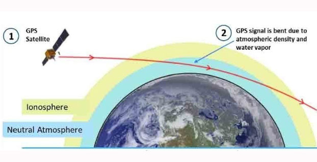
    In early June, PlanetiQ announced the successful testing of its first “Pyxis” weather sensor and is setting up for production with BCT. Pyxis collects dense, precise measurements of global temperature, pressure and water vapor — similar to data collected by weather balloons but on a global scale — using a technique called GPS Radio Occultation (GPS-RO). Among the satellite data sources currently ingested into computer weather models, GPS-RO has shown the most cost-effective, highest impact per observation on forecast accuracy. But only a sparse amount of GPS-RO data exists today.

    Pyxis is the only GPS-RO sensor in such a small package that is powerful enough to provide more than 10 times the amount of data available from GPS-RO sensors currently on orbit, and to routinely probe down into the lowest layers of the atmosphere where severe weather occurs.

    “The small size and weight of the Pyxis sensor — combined with BCT’s high-performance mission experience — will allow us to quickly field a constellation to provide the highest quality, most cost-effective weather data ever available,” said PlanetiQ FounderChris McCormick, who leads PlanetiQ’s instrument team and developed the sensors for the only GPS-RO constellation that has provided operational weather forecast data. “With 12 satellites providing 8 million data points per day, GPS-RO will easily become the most important contributor to weather forecast accuracy at a fraction of the cost of traditional weather satellites.”


  • SPAN GNSS/INS Now Available on NovAtel’s SAASM Receivers

    SPAN GNSS/INS Now Available on NovAtel’s SAASM Receivers

    OEM625S with Logo
    NovAtel’s OEM625S GNSS board.

    NovAtel’s SPAN GNSS/INS technology is now available on the company’s OEM625S dual-frequency SAASM GPS plus civil RTK receiver. The addition of SPAN offers system developers with SAASM requirements the benefit of continuously available 3D positioning, velocity and attitude (roll, pitch, yaw) for their U.S. Department of Defense (DOD) applications.

    Authorized defense customers need access to the Precise Positioning Service (PPS) for DOD applications. When keyed, the existing OEM625S board level receiver provides an RTK PPS solution by taking the raw measurements from an L-3 XFACTOR SAASM and applying them to NovAtel’s industry leading RTK algorithm. SPAN technology couples NovAtel’s precision GNSS receivers with robust IMUs to provide a more reliable, stable solution, even during short periods of time when satellite signals are blocked or unavailable. The company offers a range of IMU options to meet the accuracy and size requirements for nearly any defense application.

    NovAtel’s FlexPak-S enclosure.
    NovAtel’s FlexPak-S enclosure.

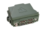
    SPAN technology is also available on NovAtel’s FlexPak-S enclosure, with multiple RS-232/RS422 serial ports for ease of integration.

  • Jedi Soliders: Army Working on Drone Hoverbike

    Jedi Soliders: Army Working on Drone Hoverbike

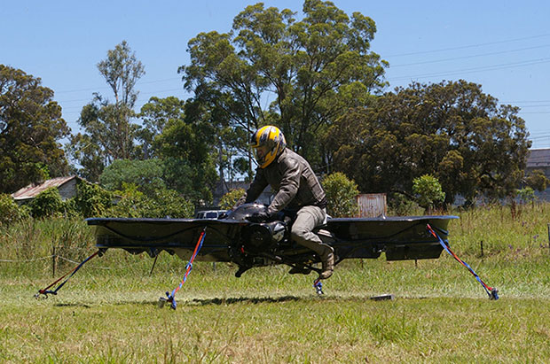
    The hoverbike, shown tethered for safety reasons, supports nearly 600 pounds, enough for soldiers and their heavy gear. (Photo: Malloy Aeronautics)
    The hoverbike, shown tethered for safety reasons, supports nearly 600 pounds, enough for soldiers and their heavy gear. (Photo: Malloy Aeronautics)

    Hover technology has long been depicted in movies like Star Wars and Back to the Future. Now the U.S. Army is teaming up with two companies to develop hoverbike technology — a cross between a motorcycle and a drone.

    SURVICE Engineering Co., a Belcamp, Md.-based defense firm, and U.K.-based Malloy Aeronautics, an aeronautical engineering firm, are developing the Hoverbike technology for the U.S. Department of Defense as part of an ongoing research and development contract with the U.S. Army Research Laboratory. The Hoverbike is being developed to operate as a new class of Tactical Reconnaissance Vehicle (TRV).

    The makers, Malloy Aeronautics, have a vision for the hoverbike beyond defense. “Its low cost and practical size lends itself to search and rescue, precision farming and cattle mustering, first-responder emergency services and cargo insertion of up to 120 kg (265 lbs) into confined spaces. We believe it would be ideal for ski and mountain rescue, airborne logistics and time-sensitive personnel insertion/extraction during major disasters,” the website says.

    As part of this strategic alliance, UK-based Malloy Aeronautics has established a U.S. office in Belcamp adjacent to Aberdeen Proving Ground to complete work on the Hoverbike. A model of the Hoverbike is on display at the Paris Air Show, which runs through June 21.

    Malloy's Drone3, a prototype of the hoverbike, was funded through a kickstarter campaign and is now being sold. According to Malloy's website, "A Californian customer of ours (Steve Mandel) received his Kickstarter Drone3 in February this year and emailed us yesterday with a photo of his new Drone3 in flight — with a new test pilot."
    Malloy’s Drone3, a prototype of the hoverbike, was funded through a kickstarter campaign and is now being sold. According to Malloy’s website, “A Californian customer of ours (Steve Mandel) received his Kickstarter Drone3 in February this year and emailed us yesterday with a photo of his new Drone3 in flight — with a new test pilot.” (Photo courtesy of Steve Mandel)

    With about 400 employees, SURVICE is a specialty engineering firm that has been providing R&D support for the U.S. Department of Defense and other industry sectors for more than 30 years.

    Formed in 2012, Malloy Aeronautics is an entrepreneurial aerospace company that develops, markets, and sells drones and Hoverbike technology to commercial and military markets.

    The video below shows the second-generation Hoverbike in a unmanned static hover. While makers say it’s capable of lifting a person of at least 100 kg, for safety and legal reasons the vehicle is being tested as a drone.

    “Establishing an office in Maryland was a clear business decision,” said Chris Malloy, managing director of Malloy Aeronautics. “The proximity to the Army Research Laboratory and U.S. defense decision makers, access to the world-class facilities through the laboratory’s Open Campus initiative, and the co-location with our strategic business partner, SURVICE Engineering, were all factors in favor of Maryland as the best choice for Malloy Aeronautics.”

    “Maryland companies do a tremendous amount of research and development (R&D) for the U.S. military,” said Jeff Foulk, SURVICE chief executive officer. “If there is a new military technology being developed, there’s a good chance that some aspect was designed, built or tested in Maryland.”

    The U.S. Army Research Laboratory is the nation’s premier laboratory for land forces and is part of the U.S. Army Research, Development and Engineering Command, which has the mission to develop technology and engineering solutions for America’s Soldiers.  RDECOM is a major subordinate command of the U.S. Army Materiel Command.

  • Sierra Wireless Offers Internet of Things Platform with GNSS

    Sierra Wireless Offers Internet of Things Platform with GNSS

    The Sierra Wireless AirPrime WP Series.
    The Sierra Wireless AirPrime WP Series.

    Sierra Wireless has introduced its next generation of the AirPrime WP Series of smart wireless modules for the development of connected products and applications for the Internet of Things. The WP Series provides an integrated device-to-cloud architecture enabling IoT developers to build a Linux-based product using a single module that sends valuable user and product data to the cloud.

    AirPrime WP is part of Sierra’s new AirPrime smart portfolio, which includes:

    • AirPrime WP Series offering an application processor, GNSS receiver, and cellular modem with an optional ultra-low power mode that reduces power consumption by 200 times, opening up new use-case possibilities for cellular connectivity.
    • Legato Linux-based platform integrated directly into the application processor of the WP modules providing an open-source application framework and  professionally maintained Linux distribution.
    • Project mangOH open hardware reference design for the WP modules offering wireless, sensor, and cloud connectivity out-of-the-box to rapidly build prototypes.
    • AirVantage cloud and connectivity services providing device, application, and connectivity management as well as an IoT data platform securely integrated into the WP.

    “With the introduction of the new AirPrime WP Series modules, we have launched a powerfully integrated device-to-cloud architecture to make it easier for our customers to innovate,” said Dan Schieler, senior vice president, Embedded Solutions for Sierra Wireless. “With an application processor running the open source Legato platform, along with the AirVantage cloud for device and application management, and a new open hardware reference design, the latest WP Series modules enable developers to quickly build connected products using a single module to run all their applications.”

    The WP Series is interchangeable and completely footprint-compatible with the AirPrime HL Series, and is available in 3G and 4G LTE variants with 2G fallback on certain modules. Like the HL Series, the new WP Series modules can be soldered down or used with a socket, for flexibility in manufacturing and inventory management. The form factor, called CF3 (common flexible form factor), will be supported by Sierra Wireless through multiple generations of both WP and HL Series product lines, providing a secure migration path for customers through multi-year deployments.

    The next-generation AirPrime WP Series offers industry-leading ultra-low power mode for applications that need to prioritize power management over constant connectivity. This deep-sleep mode is designed for industrial solar- or battery-powered applications where constant connectivity is not required, opening up new use-cases for cellular connectivity where it was previously impractical.

    For OEMs and developers, the integration of processors and device software with wireless functionality can be complex and time-consuming, even more so when modifications are required for each region and each generation of the product. If location-based services are required, a GNSS receiver must be integrated as well. Furthermore, the data from the wireless connection, the connected asset, and its location must be aggregated and delivered to enterprise applications.

    The next-generation AirPrime WP Series is designed to address all of these issues. It offers an integrated processor and a GNSS receiver, reducing the number of components, integration time, and cost for developers. The Linux-based Legato platform running on the module’s processor provides the modem services needed to get the module communicating on a cellular network, plus an application framework and secured processing space to run third-party applications. Through Legato, AirPrime WP modules are pre-integrated with the AirVantage cloud for simple, secure configuration and management of the device and its data once deployed.

  • Aspen Avionics Acquires GPS OEM Company Accord Technology

    Aspen Avionics has acquired Accord Technology LLC from Accord India. Accord Technology will operate as an Aspen Avionics company continuing to supply Federal Aviation Administration (FAA) -approved OEM GPS solutions to the aerospace industry. Support of its current client base will carry on as usual with licensed production.

    “Accord’s expertise to design and develop solutions that meet NextGen and other performance-based navigation requirements, coupled with Aspen’s display offering, create the opportunity to provide unique solutions for all aerospace segments,” said John Uczekaj, president and chief executive officer, Aspen Avionics.

    “This is a perfect blending of two companies known for their innovative culture. Aspen and Accord share the same passion to develop aviation solutions that improve situational awareness and promote flight safety at an affordable price,” said Shenoy Raghavendra, Accord Technology chief executive officer.

    The transaction, announced today, was completed on June 19 using a combination of cash and securities. NEXA Capital Partners provided merger and acquisition financial advisory services to Aspen Avionics. Also acquired was AvValues LLC, also based in Phoenix. Accord Technology LLC is a joint venture of Accord Software & Systems Pvt. Ltd., Bangalore, India, and AvValues.

    Hal Adams, founder of AvValues, has been named executive vice president of business development for the combined companies. He will be driving new business to include growing the successful NexNav product line.

    “Our combination of innovation and capabilities is unmatched in the aviation industry with the potential to deliver even more affordable, intuitive fight deck and avionics solutions. This translates into meaningful benefits to owner/operators in all areas of manned and unmanned aviation,” said Adams, executive vice president of business development.

    Aspen Avionics is a leader in manufacturing glass cockpit displays for general aviation. Founded 10 years ago, more than 9,000 Aspen cockpit systems have been installed worldwide. Aspen Avionics is globally recognized for providing the general aviation marketplace with innovative and affordable products including its Evolution Flight Display System and Connected Panel  — the first certified wireless technology that communicates with onboard avionics systems.

    Founded in 2008, Accord Technology’s expertise lies in design, manufacture and support of GPS, with Satellite Based Augmentation Systems (SBAS) such as the USA’s Wide Area Augmentation System (WAAS), receivers and sensors for OEMs for all aerospace segments, on manned and unmanned platforms. Its NexNav GPS SBAS WAAS multiple-solutions product line revolves around three key receivers: NexNav Mini, NexNav MAX and the recently introduced NexNav Micro.