PlanetiQ has started testing its first Pyxis weather instrument with successful processing of GPS signals. The Pyxis represents a new paradigm in satellite weather sensor technology that can penetrate through clouds and storms to produce the highly calibrated data required to dramatically improve weather forecasting, climate monitoring and space weather prediction, all at a much lower cost than traditional satellite weather instruments, PlanetiQ said.
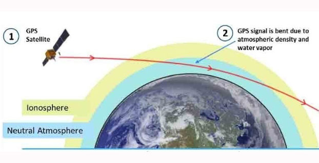
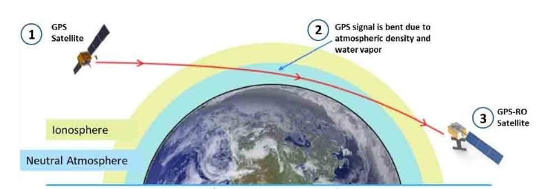
Pyxis will track GPS signals traveling through Earth’s atmosphere and convert them into dense, precise measurements of global temperature, pressure and water vapor — similar to data collected by weather balloons but on a global scale — using a technique called GPS radio occultation (GPS-RO).
Pyxis is the only GPS-RO sensor in such a small package that is powerful enough to routinely probe down into the lowest layers of the atmosphere where severe weather occurs. In addition, Pyxis is able to track signals from all four major satellite navigation systems (GPS, Galileo, Beidou and GLONASS).
PlanetiQ’s planned microsatellite constellation, with an initial set of 12 satellites launching in 2016 and 2017, will deliver more than 8 million observations per day of temperature, pressure and water vapor, or more than 10 times the amount of data available from GPS-RO sensors currently on orbit.
GPS-RO has shown the highest impact per observation on forecast accuracy among the satellite data sources ingested into computer weather models, and is particularly effective at improving predictions of high-impact weather such as hurricanes, severe weather outbreaks and winter storms. However, the amount of GPS-RO data available to date has been sparse.
The Pyxis sensor development team is based in Boulder, Colo., and led by PlanetiQ Founder Chris McCormick, who was instrumental in designing the sensors on the U.S.-Taiwan Constellation Observing System for Meteorology, Ionosphere, and Climate (COSMIC), the world’s first and only satellite constellation of proven GPS-RO sensors.
“Weather has an immense human and societal impact and affects businesses on a daily if not hourly basis, with a $9.7 trillion economic influence globally,” said Anne Hale Miglarese, president and CEO of PlanetiQ. “Improving the weather forecast and developing innovative risk analytics tools are critical to mitigate these growing costs, and the key is more high-quality weather data.”
“The Earth’s atmosphere is radically under-sampled at present especially over the oceans, which cover 70 percent of the Earth’s surface. With the speed of innovation in sensor technology, space hardware and launch, the weather forecast will dramatically change for the better in the near future,” McCormick said. “The Pyxis represents a major step forward in improving forecast accuracy for both routine weather and big storms, while leveraging the latest advances in science, technology and miniaturization to drive down costs.”
Explore further:
PlanetiQ President and CEO Anne Hale Miglarese discussed the project on The Weather Channel in August 2014.
Attila Komjathy, a NASA Jet Propulsion Laboratory principal investigator and adjunct professor in the University of New Brunswick’s Department of Geodesy and Geomatics Engineering, was named a Fellow of the Institute of Navigation in January for his work on remote sensing of the Earth’s ionosphere using signals from GNSS.
Together with free live technical support provided by practicing professional land surveyors via phone, email, message board and text messaging, JAVAD GNSS is pleased to announce the release of another innovative product, RAMS, Remote Assistance and Monitoring Services for J-Field software. J-Field is the field controller software developed for the TRIUMPH-LS GNSS receiver and the VICTOR-LS field controller. RAMS is currently available to all users of J-Field, JAVAD’s powerhouse software for survey data collection, stakeout, and computations.
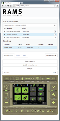
With the J-Field enabled receiver/controller connected to the Internet (via internal GSM SIM card, Wi-Fi hotspot or Ethernet), users can make their receiver/controller accessible to JAVAD’s customer support team from anywhere in the world with three button presses. “It’s like having the support person looking over the user’s shoulder,” said Shawn Billings, a surveyor from Texas.
While the TRIUMPH-LS is connected to RAMS, the user and support person share control of the receiver, giving the support person the ability to make changes to settings on the receiver or train the user remotely. “It has changed the way support is conducted, making us more efficient at determining issues and more effective in training users,” said Billings. The connection is password-protected to ensure that only those intended have remote access to the receiver.
Beyond technical support, RAMS server access is available to the user community as well. This offers the ability for project managers to remotely supervise crew efforts in the field. Because operational control of the TRIUMPH-LS/VICTOR-LS is shared between the server user and the field user, the server user (project manager) could perform the more complex operations of land surveying, such as COGO calculations and localizations, as necessary, and then allow the field user (crew member) to continue the more routine tasks of data collection.
Should the task be simpler to accomplish with office software, RAMS allows file transfer directly from the LS to the server user’s own computer and vice versa, thus enabling the project manager to easily export points, linework (dwg, dxf, shape), vectors, photos and other project-related data from the LS to his desktop. From there, he can manipulate the data in his desktop application and then copy files, with newly computed coordinates or linework, back to the LS for the crew to work with in the field. In this way, RAMS uniquely supports the obligation surveyors have to exert responsible charge over their field crews.
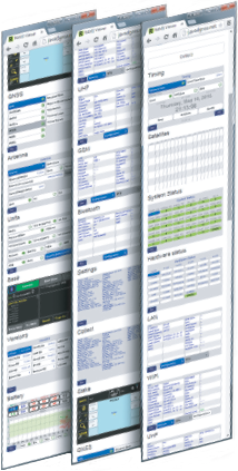
The full receiver control, the access to receiver files, the robust RTK features of the TRIUMPH-LS and the fully customizable collection settings in J-Field make site monitoring possible as well.
RAMS server can be accessed with almost any device with an Internet browser and Internet access. “I’ve used RAMS server to assist customers from my desktop computer, laptop, android tablet and even my cell phone,” Billings added. “Using JAVAD’s RAMS server requires no installation of software on the remote device, only an Internet connection and web browser.”
For those wanting to operate RAMS on their own server, the RAMS Server application is available from JAVAD GNSS. An Android version of RAMS Server is also available, allowing users to connect an Android device directly to the TRIUMPH-LS without the need for an Internet connection. RAMS for Android creates a local network between the Android device and the LS and allows a field user to see and manipulate J-Field with the Android device should it be necessary to work with the LS beyond the reach or view of the user.
For more information on RAMS, J-Field, TRIUMPH-LS, VICTOR-LS and other JAVAD GNSS solutions, visit www.javad.com, email [email protected] or call 408-770-1770.
If you are a professional land surveyor, we’d like to hear from you! Send us a brief account of how you use GNSS in your surveying work, what tips and tricks you can share with other surveyors, and what other hardware and software you are combining with GNSS to get the job done.
Submit around 300 words, although you can certainly go longer if you wish. Five winners will be chosen from the submissions received at [email protected]; winners will be chosen on the basis of clarity, liveliness, and, in some small measure, the unusual nature of the surveying tasks you perform or the way you go about them. Winners will receive $100 gift cards.
But we’re interested in hearing about straight run-of-the-mill jobs, too! Send your entries to [email protected]. Some entries may also be chosen for further development into articles for this newsletter, or GPS World magazine, or other publishing opportunities.
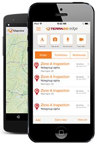
TerraGo Edge 3.6 is now available. TerraGo Edge 3.6 features enhanced support for high-accuracy GPS receivers on both iOS and Android, as well as a host of new mapping features, basemap sources and integration with Google Earth.
“TerraGo Edge’s enhanced support for EOS and SXBlue receivers helps users take advantage of real-time, high-precision GPS receivers while getting all the productivity benefits that come with the smartphone and tablet user experience,” said Brian Mickel, technical consultant, LHNav. “This is the future of GPS data collection where mobile users can integrate independent GPS receivers to get whatever level of accuracy the job requires.”
New features in version 3.6 include:
Sub-meter and cm precision with SXBlue and EOS GPS receivers for iOS and Android
Polygon and polyline note support added on iPhone and Android
Auto-drawing polygons and polylines from GPS points
Multi-note view on iPhone and Android
KML import and export added to growing list of data interfaces, improves Google Earth integration
New mapping features and editing of polygon notes
New “over-zoom” feature allows extreme map zooming on all devices and basemaps
Brand new basemap source options
TerraGo Edge is an open GPS data collection solution, helping customers replace outdated handhelds and proprietary databases with an open, modern, mobile solution that meets the needs of all stakeholders. For the field users, TerraGo Edge delivers any level of precision with unparalleled support for a full range of Bluetooth GPS receivers on Android and iOS.
For the manager, TerraGo Edge provides a real-time dashboard for monitoring field users and data collection. For GIS users, TerraGo Edge provides accuracy settings that ensure GPS data quality, with tools for QA and open export to any GIS or CAD system.
A free trial of the TerraGo Edge app for iOS or Android is available.
The latest version of the TerraGo Edge includes enhanced polygon and polyline capabilities, enriched mapping features, expanded GPS receiver integration and adds KML import and export formats. View the video above for an on-demand demo of the latest features in TerraGo Edge v3.6.
The latest version of the TerraGo Edge includes enhanced polygon and polyline capabilities, enriched mapping features, expanded GPS receiver integration and adds KML import and export formats. View the video above for an on-demand demo of the latest features in TerraGo Edge v3.6.
Telit Wireless Solutionsand Agnik are collaborating on Internet of Things (IoT) applications and Big Data analytics for connected devices in the auto, home and health industries. Agnik’s solutions expand the quality and quantity of integrated IoT apps and analytics available to customers and ecosystem partners of the industry-leading deviceWISE AEP.
The rapid proliferation of smart devices and products makes it challenging to aggregate and manage all these different data sources and also requires that this trove of data is harnessed and analyzed to extract valuable insights that help companies make more informed business decisions. The Internet of Things is already starting to transform businesses around the world. For example, in the automotive industry Big Data analytics provide a better understanding of vehicle performance, automotive business, automotive risk management, and connect with customers at a deeper level to improve efficiency and brand-loyalty. In the home, Big Data solutions are helping to manage energy consumption, maintain security while allowing entry to repair services while the homeowner is away. Individuals are wearing quasi healthcare devices on their bodies night and day.
Telit and Agnik are providing technology and analytics designed to make it easy for large and small companies to get onboard with the Internet of Things — reducing cost, time-to-market, complexity and risk versus trying to engineer a fragmented solution in house. At the core sits Telit’s Cloud-based deviceWISE, an application enablement platform for data acquisition, data and device management and data integration. In turn, Agnik converts the data from thousands of connected things into actionable business intelligence, delivered on custom web-based and mobile apps, and dashboards.
“We are honored to welcome Agnik as a deviceWISE business partner. Agnik’s leading IoT apps and Big Data Analytics further expand the number of off-the-shelf deviceWISE Ready solutions that are available to customers, MNOs and partners worldwide,” said Gideon Rogovsky, SVP, sales and marketing of deviceWISE platform at Telit. “Telit is creating a growing ecosystem of world-class IoT solution providers — ranging from the device side to applications and analytics.”
“We are pleased to collaborate with Telit and offer Agnik’s analytics-driven ecosystem of products and services to the deviceWISE AEP community,” said Hillol Kargupta, president of Agnik. “Agnik offers a comprehensive analytics platform for connected devices powered by our patented, onboard data-stream mining technology and wide range of distributed cloud-based analytics for consumer and commercial applications in connected environments.”
Agnik’s suite of analytics software products provide a wide range of powerful onboard and cloud-based tools that transform data about vehicle performance and user experience into valuable insights, according to the company. The analytics help companies in the automotive industry connect with car owners at a deeper level.
Agnik has also embarked upon a deep analytics driven path in the connected world of devices and products for industrial environments, home and health. Its collaboration with Telit will blend Agnik’s predictive data analytics capabilities with Telit’s device management infrastructure to develop a patchwork of insights into a holistic quilt of knowledge, from what would appear to be on the surface unrelated sources of information, devices, and products.
U.S. auto sales may drop about 40 percent in the next 25 years because of autonomous vehicles hitting the road, reports Bloomberg. In particular, shared driverless cars would force mass-market automakers such as General Motors Co. and Ford Motor Co. to slash output, a Barclays analyst told Bloomberg.
Vehicle ownership rates could be cut almost in half because many families would only need one car. However, driverless cars would travel twice as many miles as they return home between trips to ferry a different family member. As a result, automakers would have to shrink their production in order to survive.
The numbers are outlined in a new report by analyst Brian Johnson.
The OriginGPS Multi Spider module provides high sensitivity and noise immunity by incorporating its proprietary Noise Free Zone technology for faster position fix and navigation stability even under challenging satellite signal conditions.
SiRFstarV — CSR’s GNSS receiver that tracks both GPS and GLONASS satellites — has the CSR mbed Shield, which comes fitted with the OriginGPS Multi Spider module (ORG4572) requiring 1V8 supply, ground, UART interface and connection to GNSS capable antenna. Additional IOs are available for interrupts, turning the receiver on and off, reset, fix status and power mode information.
The OriginGPS Multi Spider is a tiny GPS + GLONASS module designed to support ultra-compact applications in which size is at a premium, such as smartwatches, wearable devices, trackers and digital cameras. It is a fully integrated, highly sensitive GPS + GLONASS receiver module measuring 7 x 7 x 2.1 millimeters.
The Multi Spider continuously tracks all GPS and GLONASS satellites in view and provides real-time positioning data in the standard industry format, defined by the U.S. National Marine Electronics Association (NMEA).
For more information about GPS/GNSS modules, visit OriginGPS.
The GN-87 multi-GNSS receiver by Furuno Electric Co.
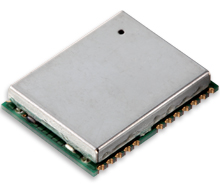
Furuno Electric Co.’s latest multi-GNSS receiver module, the GN-87, has been adopted for use in the new My Driving Pal (MDP) device.
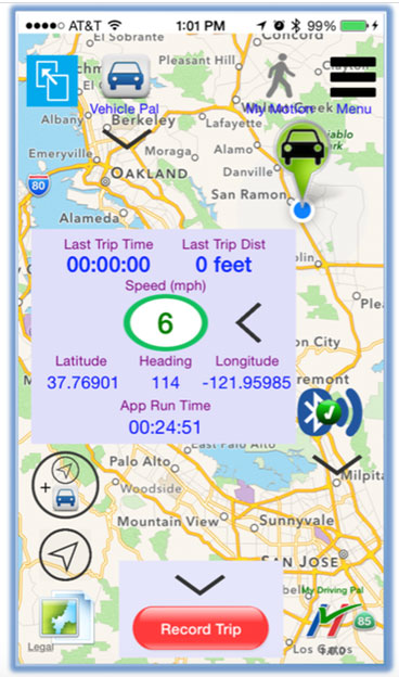
The MDP device and app communicate with each other via Bluetooth low energy (BLE). When the MDP device and a phone running the MDP app are within range of each other (approximately 15 meters), the device keeps its internal GPS in idle mode. When the phone is out of Bluetooth range and the object that is carrying the MDP device is moving (for instance, under the seat of a stolen bicycle or in the pocket of a wandering child), the MDP device activates its built-in GNSS receiver and cellular modem, tracks the asset, and immediately notifies the user on a phone via remote push notification.
The range is unlimited, because the MDP device will track the asset anywhere in the world, with an accuracy level of meters. To protect user’s privacy, all tracking data remains locally on the phone and is not transmitted to any backend server.
In April, the GN-87 receiver was adopted for the new quadcopter Bebop Drone, made by Parrot SA. The GN-87 provides positioning accuracy and smooth ground tracking because of its multi-GNSS technology, which allows it to receive more satellite data even in harsh environments such as urban canyons.
My Driving Pal (MDP) is a technology startup based in Silicon Valley that develops advanced Internet of Things solutions. MDP’s mission is to improve road safety by enabling vehicle to vehicle and vehicle to infrastructure communications. A small percentage of new vehicles are connected, but still the vast majority have no connectivity, not including motorcycles and bicycles. The MDP product delivers a suite of security, monitoring, and tracking applications, from delivering remote notification on phone if interior temperature of car gets too high, to automatically tracking the bike, if it’s ever stolen.
For more information on the MDP device (capabilities, availability, distribution, retail or partnerships), send an email to [email protected], or follow MDP on Facebook.
Differential GNSS+INS for Land Vehicle Autonomous Navigation Qualification
By Gilles Boime, Emmanuel Sicsik-Paré and John Fischer
Land-vehicle autonomous navigation requires centimeter-level qualification tools to enable confidence build-up for delivery to open-road traffic insertion. External positioning sensors over a dedicated road section can be replaced with an embedded high-accuracy, highly responsive epoch-by-epoch differential GNSS receiver coupled with an inertial navigation system. The demonstrated absolute accuracy and mobility extends the potential test area and minimizes cost for multi-environment validation.
Cover courtesy of Mercedes.
Personal cars and commercial trucks are continuously improving the driver experience and safety thanks to integration of more significant and machine-assisted control systems. Advanced driver-assistance systems (ADAS) are now integrated in all luxury cars and moving into mainstream products. Technologies covered by ADAS are specific for each car integrator, but increasingly they include now involving more safety features, such as driver assistance and partial delegation to autonomous control for small maneuvers such as lane control. The generation of ADAS systems introduced in early 2015 on high-end models are engaging more intelligence from the control system such as:
Lane departure warning system
Speed assistance and control
Driver assistance and control
Autonomous emergency braking.
It is not only individual drivers who want this technology, but also governments that are getting involved to prevent accidents and minimize the economic impact associated with them. In the European Union, the general safety regulation 2009/661 was the first step to engage member-states to act as a regulator to mandate car safety improvements. The European Transport Safety Council, a non-profit private association, released in March 2015 a position paper titled “Revision of the General Safety Regulation 2009/661.” It promotes the introduction of lifesaving technologies like intelligent speed assistance, autonomous emergency technology including all speed and pedestrian detection, and lane-departure warning systems as the next step of regulation.
Car manufacturers are not far behind. They understand their customers’ expectation of minimized risk and enhanced driving experience. Telematics is also a path to convert a single vehicle into a fully intelligent, connected and entertainment object with an associated high value. So every car manufacturer is willing to be seen as a technology master.
Toyota, for example, plans to integrate collision-prevention technology in all its mainstream and luxury cars by 2017. The ADAS new generation focuses on radar-activated cruise control technology for the collision-prevention system. The control system maintains distance from a vehicle ahead and can stop the car if driver doesn’t react. The next step is to monitor driver attention with sensors like cameras focusing on the driver’s eyes, and the pressure of the hand on the steering wheel.
However, no fully driverless car is expected in the next 10 years. This technology is limited by legal issues and the lack of reliable nationwide mapping data.
Since the technology must be fully proven to prevent any lethal threat on the user and other drivers, most car and truck companies are working actively on qualifying driverless technology today. Nissan began testing driver-assist technology on open-road traffic in Japan in late 2013. It enables highly advanced systems such as lane-keeping, automatic lane change, automatic exit, automatic overtaking of slower or stopped vehicles, automatic deceleration during congestion on freeways, and automatic stopping at red lights. This is a step towards attaining fully automatic driving, targeted for 2020 by Nissan.
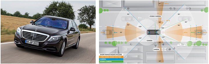
Some European manufacturers such as Daimler Benz are also early adopters. Daimler/Mercedes uses the Bertha Benz prototype car to test autonomous driving technologies. It merged multiple vision, radar and GPS sensor with digital map to monitor an open-road 100-kilometer trip in August 2013 (Figure 1).
Figure 1. Bertha Benz test car, left, running fully autonomous 103-kilometer trip in open road including 27 percent narrow urban roads. Right, networked sensor systems of the S 500 Intelligent Drive research vehicle.
All manufacturers are building driverless capability into their technology demonstration concept cars:
Mercedes with F 015 Luxury presented at the Consumer Electronic Show, early 2015;
Audi with Prologue, an extrapolation of test car RS7 concept equipped with SuperFast driverless pilot;
BMW’s electric i3 car is integrating ActiveAssist technology that enables portions of drive to be without any manual intervention, such as car parking and autonomous rally to a meeting point;
Google’s self-driving vehicle that conforms to California license requirements for driverless tests in open traffic;
Tesla model SD autonomous test car.
Although most market leaders agree that this is not a technology for mainstream production in the next few years, they all work very efficiently to master the technologies. It is a big challenge to integrate all the sensors and the navigation functions to autonomously and accurately position the vehicle on a map. The whole system must be certified to prevent any liability in case of a crash, a case that would engage the solution provider and the vehicle manufacturer.
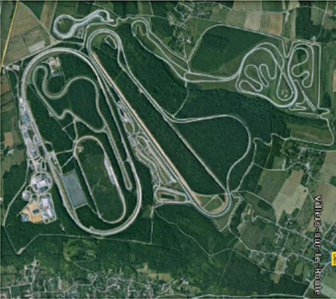
A large part of the qualification task will benefit from simulations and integration testing platforms in realistic conditions. At the very least, a very robust final open-space validation test must take place. Car manufacturers/integrators are using private test facilities in open air to perform serious trials before proceeding to real traffic conditions. Renault uses a 10-square-kilometer facility in France (Figure 2) to perform private tests in a protected area.
Figure 2. Renault outdoor test center at Aubevoye, France.
New autonomous car drive tests have mandated equipment enabling measurement of the car’s position on the track with an extremely high precision and repeatability. There are two competing technologies to do this:
Install many location sensors on the test track;
Use a general absolute positioning system.
Here we focus on an absolute positioning system that is affordable, easy to install and low maintenance. It is based on two main assertions:
The autonomous pilot can position accurately on the test track;
The test track is accurately referenced to the absolute positioning system.
We focus more closely in this article on the first assertion; the second one can be covered with a specific calibration trial where equipment, as discussed further, can be used in quasi-static mode and experience consistent accuracy. Let us have a deeper look at the candidate position technologies to verify autonomous pilot accuracy.
Positioning Technologies
Many technologies have been proposed to obtain vehicle position on the course. However, they all must be compatible with a reliable mapping database. Given the lack of consistent road infrastructure equipment with alternative capabilities, GNSS positioning is the sole enabling method to fit to a map every place around the world. That is why driverless systems always include a GNSS sensor to help other data matching with the map. The versatility and low cost of GNSS positioning makes it a candidate for open-air validation as well.
Standalone Standard Positioning Service GPS. The SPS single-frequency GPS receivers are included in so many nomadic appliances today that they are a commodity. Since their introduction 20 years ago, their performance is well understood. Some trials were performed in different area profiles with satellite constellation position dilution of precision (PDOP) < 2. Worse results were obtained from deep urban canyons in downtown Seattle, Wash.
For every technology, the relevant performance for the test course is the lateral error to the expected center of the lane in the two horizontal dimensions, referred to as 2D or N/E for orientation north and east.
For standalone SPS GPS, the lateral error standard deviation in 2D can be as high as 46 meters and have peak errors up to 660 meters. Lateral error in 3D can be as high as 20 meters with peak errors up to 175 meters.
Such performances are out of range for any positioning verification. It can only deliver a rough estimate of the point on the map, but would not provide tight correlation with other sensors for the navigation system.
Hybridized IMU and SPS GPS. Coupling of an absolute navigation GPS receiver with an inertial measurement unit (IMU) can mitigate corruption of the navigation solution when intermittent GPS signal outage is encountered. The hybrid approach is beneficial on any difficult signal transmission path from the satellite that is not line-of-sight: in urban canyons, deep foliage, under bridges, tunnels and in any multipath area. It also yields benefits in the very short term (less than a few seconds) for dispersion on the position computed from the sky.
Over the last 10 years, the combined benefits of micro-electro-mechanical sensors (MEMS) and tight coupling algorithms have raised the bar of positioning accuracy. It enables smoothed position along track and dead reckoning (DR) in case of GNSS signal outage.
Lateral error standard deviation in 2D is lowered to 2.3 meters and peak error up to 10 meters. However, this performance is still too poor to validate a vehicle position in the lane.
Hybrid Differential Single Frequency and IMU. The next step to mitigate systematic errors of the GNSS system is to use a set of multiple reference receivers in the vicinity of the area covering the test course. The reference receivers are static. The position of the reference is determined using long-term averages to mitigate constellation errors. A minimum for a position fix of 20 minutes is commonly reported. Then the position error standard deviation in 2D is less than 2 centimeters for baselines shorter than 100 kilometers.
For a MEMS integrated with a standard SPS GPS single-frequency receiver with DGPS correction on a mobile platform moving at less than 70 km/hour with HDOP < 1.4, Table 1 compares performance in a 2013 test.
Hybrid Differential Dual-Frequency Carrier Phase and IMU. The GNSS solution can be further improved, taking into account both L1 and L2 frequencies to mitigate propagation error and carrier phase to achieve ultimate signal accuracy. The combination of both helps solve ambiguities associated with the carrier-phase technique. When combined with a MEMS IMU, accuracy confirmed with HDOP < 1.6 is:
Lateral error standard deviation down to 0.18 meters;
Peak error of 0.6 meter.
However, this is still insufficient accuracy when compared to 0.1 meter required for verification testing.
With such low-cost IMU, GPS outages produce a rapidly increasing lateral error over elapsed time. The lower the speed, the poorer the position result.
Another limitation common to many differential solutions is the turn-on delay for the solution. It is also a repetitive issue in case of disruption of the GNSS solution. It extends the delay to recover from DR situation.
Geodetics’ Epoch-by-Epoch
Geodetics Inc. has developed a new class of instantaneous, real-time precise GPS positioning and navigation algorithms, referred to as Epoch-by-Epoch (EBE) and employing hybridized dual-frequency differential GPS with a high-performance IMU.
Compared to conventional real-time kinematic (RTK), integer-cycle phase ambiguities are independently estimated for each and every observation epoch. Therefore, complications due to cycle slips, receiver loss-of-lock, power and communications outages, and constellation changes are minimized. There is no need for the initialization period (several seconds to several minutes) required by conventional RTK methods.
More importantly, there is no need for re-initialization immediately following loss-of-lock problems such as those that occur when a mobile GPS receiver passes under a bridge or other obstruction, or when it loses satellite visibility during a shaded portion of road. In addition, EBE provides precise positioning estimates over longer reference-receiver-to-user-receiver baselines than conventional RTK.
This feature supports testing for long-range operations, for example, such as positioning a vehicle on a lane. The reference receiver is set in the vicinity of the test center track.
EBE requires the use of a minimum of two receivers, each of which is tracking a common set of five or more satellites and providing simultaneous dual-frequency phase data. Typically, one of the receivers is stationary, but this is not a requirement.
EBE has been proven utilizing dual-frequency receivers and operating at distances of up to 50 kilometers from the nearest base station in unaided mode. Additionally, the EBE algorithms operate in a network environment and make optimal use of all GPS measurement data at each epoch, gracefully degrading the position accuracies when some measurement data are not available. Furthermore, the system will make use of an IMU system, compensating for outages when line-of-sight to the satellites is blocked. This produces a robust and more reliable system.
Epoch-by-Epoch can deliver several benefits including:
Computationally efficient algorithms that provide a position estimate based on a single epoch in several milliseconds. This allows the real-time position estimate to be computed on the user platform (assuming reference station data is sent to the user platform).
An initialization period is not required. Since RTK requires some period of time (that can be measured in seconds to minutes) to perform ambiguity resolution, this is an important capability for platforms that:
require high accuracy (for example, for end-game scoring);
cannot see the satellites until launch;
have short flight or test course duration;
A re-initialization period following loss-of-lock is not required, unlike RTK, which needs to restart the integer-cycle phase ambiguity resolution process. This is another important capability because vehicle monitoring is considering EBE for dynamic applications where loss-of-lock and loss-of-data are likely.
However, it must be mentioned that many of the GPS receivers in use by the test (and training) community today do not support this dual-frequency requirement. Hence, those systems could not realize the maximum benefit.
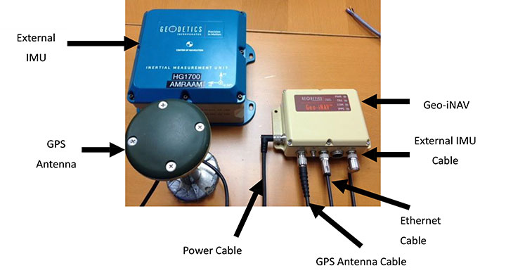
This technology is implemented in a rugged modular platform (Figure 3) with three main units:
A dual-frequency GPS antenna,
An integrated INS coupling GPS receiver with either an internal MEMS IMU or external IMU,
An external fiber-optic gyroscope (FOG) IMU for high-end accuracy and reliability. The external IMU is optional and dedicated to increasing the DR capability.
Figure 3. Dual-frequency differential navigation unit hybridized with external fiber-optic gyro.
Performance. Tests have been performed in conditions close to the land-vehicle navigation validation. It is based on measurements on-the-fly with no post-processing except for evaluation of the error.
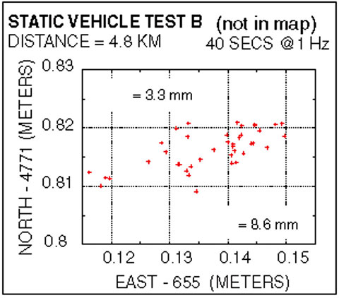
The first case is a static position of the rover 4.8 kilometers away from the reference receiver. Positions are updated once per second. The system includes a FOG IMU. the lateral error peak is less than 4 centimeters. Bias error is less than 1 centimeter. See Figure 4.
Figure 4. Single point error when rover is static.
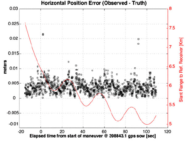
The second test case is with a high-dynamic mobile platform, moving at a speed of 200 km/h, with an average distance from the reference to the rover of 6 kilometers. Lateral error standard deviation is 0.5 centimeters, peak error is less than 2.2 centimeters. Bias error is lower than 0.2 centimeters (Figure 5).
Figure 5. Dynamic trial test single point error.
The performance in these test cases meets the expected accuracy for validation of autonomous navigation.
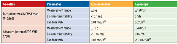
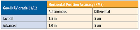
One last method to increase accuracy is to switch to a different class of IMU performance, from tactical grade to advanced. When in the line-of-sight of the GNSS sky-view, the performance is the nearly the same.
Conclusion
A real-time, differential Epoch-by-Epoch, dual-frequency carrier-phase GPS receiver, tightly hybridized with a high-performance IMU can provide absolute error lower than 5 centimeters in the 10-kilometer baseline range of the reference static receiver. This is fully adapted to the qualification of driverless auto-pilot systems for the targeted year of 2020. It can avoid the need to use complex theodolite and vision calibration systems. It provides maximum flexibility and minimum sustaining costs.
Acknowledgment
This study has been made possible thanks to materials provided by Geodetics Inc. and the advice of Jeffrey A. Fayman, vice president, Business & Product Development, Geodetics Inc. The results displayed in Figures 4 and 5 are from a test with a medium-sized UAV from Allied Drones, model EF44 high-endurance quad.
Manufacturers
The Geo-iNAV family is a range of GPS-aided INS solutions available in different configurations, including various GPS receivers (L1, L1/L2 RTK, SAASM), internal MEMS or external FOG IMU. As part of this family, the Geo-RelNAV provides differential GPS relative navigation capability, the Geo-hNAV includes a dual GPS antenna receiver for static heading measurement capability, and the Geo-PNT combines position and attitude measurement with precise timing distribution.
Gilles Boime is is chief scientist for Spectracom. He is involved in GNSS signal generator, hybridized navigation platforms, GNSS timing and synchronization innovative solutions build-up. He holds an engineering diploma in telecommunication from Institut Superieur d’Electronique de Paris.
Emmanuel Sicsik-Pare is strategic product manager for Spectracom. He is involved in timing and navigation products and systems definition and application market monitoring. He holds a M.Sc degree from Telecom Bretagne.
John Fischer is CTO of Spectracom. He has more than 30 years experience creating navigation and communications systems, received his master’s in electrical engineering from SUNY at Buffalo. Prior to joining Spectracom, he worked in radar, command and control, and wireless systems.