Author: GPS World Staff

  • Jammer Hunting with a UAV

    A fully autonomous, unmanned aerial vehicle (UAV)-based system for locating GPS jammers, currently under development, seeks to localize a jammer to within 30 meters in less than 15 minutes in an area comparable to that of an airport. Ultimately, the design team targets the ability to locate multiple, simultaneous jammers, and navigate in intermittent GPS and GPS-denied environments using a combination of GPS and alternate navigation aids. The system should be inexpensive and built from commercially available or open-source parts and software.

    By James Spicer, Adrien Perkins, Louis Dressel, Mark James, Yu-Hsuan Chen, Sherman Lo , David S. De Lorenzo and Per Enge, Stanford University

    The aviation community worries about GPS jamming. Recently, it struggled to find so-called personal privacy devices on Newark’s Liberty International Airport and traveling the nearby New Jersey Turnpike.

    A number of unintentional jamming incidents took a long time to resolve. The disruption from an intentional, malicious jamming attack could be far worse. Airport authorities should be prepared to locate and shut down a coordinated attack by numerous jammers capable of disrupting the GPS service over an entire airport.

    The closure of a major airport for the many hours or days it would take to locate even a couple of backpack-sized transmitters would be not only be highly disruptive in flights delayed or diverted, it would negatively impact the confidence of the flying public.

    Any system in place to mitigate this threat must be inexpensive enough to be deployed at least at the nation’s major commercial airports, autonomous enough to be operable with limited training and certification, and rapid and accurate enough that a jammer can be routinely apprehended by ground-based law enforcement. It must be able to navigate successfully in GPS-denied environments using alternative position, navigation and timing (APNT), and have the range and capacity to search an airport-sized area as well as the approach corridor leading to runway touchdown.

    This article describes such a system and device presently in research and development: the Jammer Acquisition with GPS Exploration & Reconnaissance (JAGER).

    Vehicle Design and Operation

    The JAGER UAV is a based on a commercially available, multi-rotor airframe modified to suit the mission specifications. The 1.2-meter diameter octocopter has a maximum takeoff weight of 11 kilograms (24.2 pounds), a top speed of 20 meters/second (m/s, 45 mph), and can fly unloaded for up to 30 minutes.

    We have replaced the battery tray with our own carbon fiber design that allows us to carry 16 Ah of lithium polymer batteries for a maximum power draw of 4 kW. This extra capacity means that even with a 5-kilo experimental payload, the present craft can remain aloft for up to 15 minutes without recharging.

    The payload plates are also custom-made from carbon fiber, and it is to these that the UAV’s experimental payloads are mounted (see FIGURES 1 and 2). One payload plate is flown at a time, and is secured on top of the airframe with a quick-release mechanism. This modularity allows for individual experiments to be mounted to their own payload plate and ground-tested before being secured to the UAV. Different experiments can be switched out rapidly for efficient use of battery capacity and flight time.
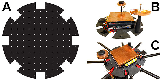
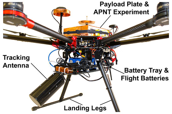
    Figure 1. (A) Diagram of the payload plate showing regularly spaced mounting holes. (B) Plate with APNT experiment mounted. (C) Payload plate / experiment assembly secured atop JAGER UAV.
    Figure 1. (A) Diagram of the payload plate showing regularly spaced mounting holes. (B) Plate with APNT experiment mounted. (C) Payload plate / experiment assembly secured atop JAGER UAV.
    Figure 2. Image of the vehicle showing the battery tray slung beneath the central body, the APNT experiment and payload plate secured on top, and the jammer-hunting antenna mounted at the front.
    Figure 2. Image of the vehicle showing the battery tray slung beneath the central body, the APNT experiment and payload plate secured on top, and the jammer-hunting antenna mounted at the front.

    The plate itself also offers flexibility for component mounting. Regularly spaced, threaded holes across the plate mean components’ positions can be easily changed to find an optimal configuration. This can be particularly useful for minimizing interference between computers and noise-sensitive components such as antennas and magnetometers.

    Software. We modified existing, open-source autopilot software to fly the mission. The craft is fully capable of completing a mission autonomously, but also can be taken over by a human pilot if necessary. A ground station also can be used to send commands to the octocopter, but is primarily used to monitor UAV location, battery life, and jammer belief state.

    The autopilot software also has been adapted to communicate with various vehicle payloads. Experiments using APNT equipment, for example, pass their data to the autopilot, which will combine these signals with its own GPS data for accurate navigation in areas where the GPS signal might be intermittent or unreliable. In return, the autopilot can be used to pass data to experiments reliant on altitude, attitude, atmospheric pressure or location information.

    The ground station monitors instruments’ data and status in real time. This not only allows for control of airborne experiments, but also straightforward ground testing. Synthetic autopilot data can be fed to an experiment to ensure that all systems are performing correctly before they are mounted on the vehicle for flight tests.

    APNT Overview

    Key to navigating in a GPS-denied environment is the use of signals from APNT networks for location determination. The proposed system should be able to navigate using any or all available APNT signals, and should weight each one according to its strength and reliability in order to formulate the most accurate estimate of both its own and the jammer’s position.

    Here we describe the use of the universal access transceiver (UAT) and distance measuring equipment (DME) network for our APNT signals. The UAT signal has been implemented by the Federal Aviation Administration (FAA) in the United States as part of automatic dependent surveillance–broadcast (ADS-B), and is transmitted through a network of terrestrial ground stations.

    The ADS-B network was only completed across the contiguous United States in 2014, so it is new compared to established cellphone networks. It is more comprehensive than many other terrestrial systems, so that coverage of most airports is guaranteed. While GPS reception requires an unobstructed view of the sky, UAT reception requires a direct line of sight to a transmitting tower. However, the flatness of terrain surrounding most airports as well as the UAV’s airborne vantage point ensures that UAT signals will probably be visible throughout most jammer-seeking missions.

    The APNT equipment used for navigation by the JAGER UAV consists of UAT (978 MHz), DME (982 to 1213 MHz), and GPS (1575.4 MHz) antennas, a multichannel transceiver to combine the two signals, and a computer for data processing (see FIGURE 3). A dedicated lithium-ion battery powers the entire APNT payload. The current system does incorporate GPS to estimate the time offset, but future iterations of the system will derive time from sources other than GNSS so that true GPS-denied navigation is possible.
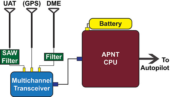
    Figure 3. Schematic of the APNT configuration on board the JAGER UAV. Resulting location information is passed to the autopilot for navigation.
    Figure 3. Schematic of the APNT configuration on board the JAGER UAV. Resulting location information is passed to the autopilot for navigation.

    The UAT antenna receives multiple signals from visible ADS-B ground station transmitters. The transceiver combines these with a GPS timestamp, and the data is passed to the APNT computer for analysis. Based on knowledge of the absolute locations of the ADS-B antennas, the range of the vehicle from each antenna can be calculated, which in turn can be used to trilaterate the vehicle’s absolute position. This position is then passed to the autopilot for the UAV’s navigation, while the status of the equipment and signal strength are passed down to the ground for monitoring in real-time.

    The necessity of using GPS signals as an accurate timing system is a current limitation, as navigation in GPS-denied conditions is clearly not possible while we are using GPS as a clock. As mentioned eariler, future designs will derive time from non-GNSS sources, such as chip-scale atomic clocks or the terrestrial ranging signals.

    Carrying an onboard computer allows for real-time processing of the terrestrial alternative navigation signals.  However, there are a few limitations to the use of these signals. First, the vertical position is difficult to calculate due to the geometry of terrestrial signals as well as the sparsity of visible station at low elevation. This is solved by using a baro-altimeter. Second, DME signals do not provide a pseudoranging function. Current work sponsored by the FAA is developing a DME pseudoranging capability. As the technology matures, we will improve the hardware and algorithm that can be integrated into future JAGER designs, resulting in lower weight and power overhead for the APNT payload.

    Tracking Overview

    GPS jammers do little more than emit signals in the GPS frequency range. Because the signals from GPS satellites are so weak by the time they reach the Earth, ground-based jammers do not have to be especially powerful to overwhelm GPS in their immediate vicinity. A jammer is no more than a ground-based radio-frequency source radiating within the GPS spectrum.

    The JAGER system will autonomously locate the nearest beacon emitting electromagnetic signals at the target frequency: the GPS frequency in this scenario. Testing such a system is difficult due to the illegality of jamming the GPS signal within the United States. We instead test the system using a powerful Wi-Fi beacon as a proxy for the overpowering jammer. Excepting the target frequency, the procedure to locate the jammer is identical to the GPS case.

    To receive the jamming signal, the front of the craft carries an antenna optimized to receive signals of the target wavelength; the current antenna has a 60° cone of maximum sensitivity. It is angled downward 30° from the horizontal, so that the craft can receive all signals from the horizon to 30° from vertical. This gives the UAV visibility over most of the space in front and underneath it. Like the other payload equipment on the vehicle, the antenna is secured with a fast-release mechanism so that it can be easily swapped out if necessary. For Wi-Fi tracking, we use a Yagi antenna with 60° beamwidth and 9 dBi gain. In upcoming trials, we will test different antenna configurations (such as dual antennas, small antenna arrays, and directional antennas augmented with omni-directional antennas) to determine benefits of these different layouts.

    Signals from the antenna are passed into a module that converts the Wi-Fi data to serial, then from serial to USB. A single-board Linux computer with a quad-core processor then analyzes the signal data (see FIGURE 4). The hardware used to locate the jammer weighs 160 grams, so has negligible impact on the vehicle’s flight time or range.

    Figure 4. Schematic of the tracking system on board the JAGER UAV. The resulting believed location of the target is passed to the autopilot.
    Figure 4. Schematic of the tracking system on board the JAGER UAV. The resulting believed location of the target is passed to the autopilot.

    To find the jammer’s location, the UAV performs a controlled yaw spin while recording the strength of the jamming signal. On the basis of the signal landscape surrounding the vehicle, the computer estimates the jammer’s location and sends a message to the autopilot instructing the craft to fly in that direction (or, more accurately, in a direction that optimally improves the ability of JAGER to find the jammer quickly). In return, the autopilot updates the tracking computer and ground station as to the vehicle’s position.

    After moving a certain distance towards the jammer’s believed location, the craft repeats the spinning maneuver and starts the process again. Although rotating only the antenna might increase the speed of the operation, the energy required to carry the necessary antenna-rotation mechanisms for the duration of a flight is more than that needed to spin the entire craft.

    The tracking algorithm is not as straightforward as gradient ascent or homing, and the vehicle will not always fly in the direction of greatest signal strength. The operational area is uneven, and may include buildings, towers, or airplanes, resulting in a complicated RF environment. Signals are scattered, diffracted and reflected, meaning that an algorithm that simply follows the strongest signal will not always converge on the actual jammer location.

    To decide the optimal path from the vehicle’s present location to the jammer’s believed position, the tracking algorithm makes use of partially observable Markov decision processes (POMDPs). POMDPs model decision processes where the underlying state of the system (that is, the location of the jammer) is never completely known, and maintain a probability distribution over the set of all possible states.

    The entire deployment area (an airport and its environs, for example) is split up into a square grid. For every possible combination of jammer and vehicle grid square locations, the signal strength and direction that would result is calculated offline prior to deployment and stored in a database on the tracking computer.

    During the mission, the UAV records its own position and the sensed jamming signal’s strength and direction. The jammer location that would correspond to this result is retrieved from the database, as well as a measure of the strength of this belief state.

    Once the craft has a belief as to the location of the jammer, it moves to a new location in the jammer’s believed direction before taking another measurement of signal strength. The new location and new measurement are combined, and the updated corresponding jammer location is retrieved from the database. This process is repeated until the vehicle believes itself to be right above the jammer, at which point a photograph is taken, the ground station is notified, and the hunting mission is complete.

    Having found the jammer, the system can be programmed to execute a wide range of operations. These include reporting coordinates and a live image of the believed jammer location back to the ground station, hovering above and tracking the jammer if it begins to move, landing at the jammer site, or returning to base.

    We calculate and store the POMDP decisions in advance of the flight. This strategy has some advantages. First, it allows for almost instantaneous decision-making. This is because the algorithm’s decisions are based solely on the vehicle’s current location and sensory observations and not on any previous states (a defining characteristic of a Markov decision process). The craft needs only to observe its current state in order to look up its next move in the database. This enables rapid tracking in flight.

    A second advantage is that safety checks can be pre-programmed into the database in advance of deployment. While JAGER is programmed to move towards the grid square believed to contain the jammer, it can also be programmed to avoid or take special precautions when moving towards or in the vicinity of certain squares in the grid (also called geo-fencing). In an airport situation, for example, the vehicle would avoid moving into the square containing a control tower or ground-based antenna, or would fly at a minimum altitude over buildings and taxiways to avoid collisions.

    Finally, the integration between the autopilot and the tracking software can provide other important safeguards: in the proof-of-concept system, any navigation decision taken by the software can be relayed to the ground for human verification before the UAV begins to move. This supervised mode of operation lends itself to a seamless migration path to fully autonomous operation (always overseen by a human operator).

    However, one disadvantage of calculating and storing decisions in advance is the storage space needed on the vehicle. Because the result of every possible combination of vehicle and jammer locations within the grid is calculated, the size of the database grows quickly with increasing numbers of possible positions (and states). The larger the grid or the greater the required accuracy, the more space is needed to store the database. With current algorithms, the database needed to locate a jammer to within 30 meters in an area the size of an airport requires 15 gigabytes of storage space, resulting in longer lookup times during flight.

    We are considering several strategies to mitigate this disadvantage, including better compression, more effective search algorithms, and uploading from a ground server only the parts of the database that correspond to the vehicle’s current operational area. Another strategy is to use an adaptive mesh that changes in resolution depending on the jammer’s belief state: at low certainty the database resolution is low, but increases in the appropriate area as the jammer’s location becomes more certain.

    Another disadvantage of pre-solving the decision-making process is that the system must be reconfigured for every site in which it is deployed. The specifications of the tracking algorithm will change depending on the requirements of the operating area. The grid size, shape and absolute location must change to suit the area being protected. The resolution of the grid depends on the required accuracy of the tracking system, and restricted or prohibited locations must suit the terrain, buildings and geological features of the deployment space. For example, a lead JAGER vehicle could be adapted and tested to suit a particular airport, and then the bespoke algorithm and database uploaded to backup vehicles in that airport’s fleet.

    APNT Performance

    During the Joint Interagency Field Experimentation (JIFX) event at Camp Roberts, California, in November 2014, we tested the APNT system by deploying the vehicle with GPS, UAT and DME antennas simultaneously recording data. GPS receivers on the ground were used to collect reference measurements to estimate the time of transmission of the signals from the APNT sites. All signals were recorded at an altitude of 275 meters above ground level (600 meters above sea level), at four different points roughly 800 meters apart, and the data analyzed for comparison. As expected, the UAT broadcast was noisier than the GPS signal. However, it was possible to calculate a range from the UAT data that was accurate to within 16.6 meters of the GPS reference position, well within the 30 meters error bound specified in the project specification (see FIGURE 5).
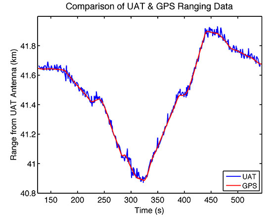
    Figure 5. UAT range deviates from GPS derived range-estimate by an average of only 16.6 meters throughout the duration of the test flight.
    Figure 5. UAT range deviates from GPS derived range-estimate by an average of only 16.6 meters throughout the duration of the test flight.

    While UAV navigation using APNT was done offline in post-processing for these tests, with planned algorithm improvements and hardware acceleration the UAT signal can be used to get real-time position information nearly as accurate as that from GPS. Thus the JAGER UAV can be navigated with comparable reliability in both GPS and GPS-denied environments.

    Terrestrial APNT signals will be received at a wide range of power levels. This effect is not observed with the GPS network, as the different satellite signals are broadcast from such a great distance that any differences in received signal strength are relatively small by the time they reach Earth. For terrestrial networks, signals from transmitters close to the receiver can be many times stronger than those further away, which can result in two issues: 1) interference where one signal overwhelms another, and 2) inability to process a signal if the receiver does not have adequate dynamic range to capture strong and weak signals clearly.

    This problem was observed in our tests, as we were receiving two signals: one 13.7 kilometers (DME) and the other 43.5 kilometers (ADS-B UAT) from our test site. Calculating accurate ranging estimates from the two required determining a gain setting that had dynamic range adequate for receiving both signals clearly.

    Vehicle Performance

    During experimental testing, the vehicle itself also underwent rigorous assessment of its performance under different conditions. Due to the delicate and often expensive nature of the payloads and experiments made possible by the JAGER platform, it is essential that the vehicle perform as expected, and that there are multiple procedures in place to protect the payloads in case of vehicle failure.

    Because the open-source autopilot had never been used with such a large vehicle, we first ground-tested the craft’s flight control and stability. The vehicle was tethered and constrained to move in only one axis, and ropes were used to control its roll. While altering autopilot variables controlling roll and pitch feedback loops, we measured the vehicle’s response to impulsive disturbances and the time taken for it to right itself when upset. In this way we could tune the control gains and verify that the vehicle would be exceptionally stable during flight in even the most challenging atmospheric conditions. While we preferred to fly in the early morning hours to exploit clear air and lower winds, we did perform tests with momentary gusts of up to 7 m/s during envelope expansion flights.

    We tested the vehicle with two accelerometers on board to measure how the rotors’ vibrations affected the rest of the craft. One accelerometer was attached to the airframe itself, while the other was secured to the payload plate. A comparison of the acceleration data recorded by the two instruments revealed that the payload plate experienced significantly less vibration than the airframe during flight, and both measurements remained well within the tolerances advised by the airframe manufacturer.

    Two crucial flight modes also were tested before payloads were flown on the vehicle. Both altitude-control mode and position-control mode were tested to ensure that they could precisely constrain respectively the vehicle’s altitude and absolute position in a range of atmospheric conditions. Results showed that in altitude control mode, the vehicle’s z-coordinate was held constant to within ± 0.5 meters. In position control mode, its x- and y-coordinates remained within ± 1.0 meters (or a single vehicle length).

    The success of the JAGER tracking mission also depends on accurate position measurements from the UAV. Operators must be confident in the vehicle’s position, so that ground forces can easily apprehend the located jammer, and also so that there is confidence in the success of safety protocols including geo-fencing, no-fly zones and minimum flight altitudes.

    In addition to the geo-fencing and flight precautions taken by the tracking algorithm, the JAGER UAV has several other safety procedures executed automatically by the autopilot. A non-catastrophic error in the flight systems or payload is transmitted to the ground station for human troubleshooting, and commands can be sent to the vehicle as to how to proceed.

    Finally, should we continue operations and allow its batteries to get sufficiently low, the vehicle will automatically return to launch site for landing and battery replacement. A catastrophic failure such as the loss of a motor will result in an immediate controlled landing. The craft can also be commanded from the ground station to land or return to launch, and can be taken over by a human pilot at any time.

    Other tests verified that the vehicle has the range and endurance to be successful when deployed in an airport setting. When fully loaded with APNT and tracking payloads, the UAV exhibited a top speed of 10 m/s, enough to cover the length of an A380-capable runway in less than 5 minutes. A 20-minute flight endurance means that even including hovering during jamming signal observations by the tracking antenna, the JAGER system can hunt easily and effectively throughout an airport-sized area. Furthermore, we continue to explore techniques to improve dash capability, including reducing the weight of the APNT payload, and we anticipate describing results of these efforts in future reports.

    Electromagnetic Interference

    Because of the payload tray’s small area (0.5 m2), electromagnetic interference (EMI) between APNT components was a significant issue during testing. The GPS and UAT receivers are extremely sensitive to interference from other sources emitting in the frequency ranges to which they are tuned. The APNT computer, by contrast, is composed of various processors, clocks, drives and power boards that emit powerful electromagnetic noise at a wide range of frequencies as a byproduct of their normal operation.

    The size and mass of the APNT computer board meant that it had to be mounted in the center of the payload tray to avoid unbalancing the UAV. That left a maximum 7 centimeters of space around the computer on which to mount the two antennas (see FIGURE 6). With no shielding, the EMI from the computer proved powerful enough to completely overwhelm the GPS, UAT and DME network signals, making navigation and position estimation using any network impossible.
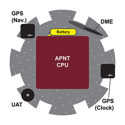
    Figure 6. Diagram showing the APNT experimental payload, and the proximity of the EMI-radiating CPU to numerous antennas.
    Figure 6. Diagram showing the APNT experimental payload, and the proximity of the EMI-radiating CPU to numerous antennas.

    The EMI problem was solved in three ways. Masts were used to raise the receiving antennas to a height of 19 centimeters above the payload tray, the maximum height at which a mast collapse wouldn’t cause catastrophic rotor and vehicle failure.

    The antennas also were moved around the edge of the payload tray so as to be furthest from the system components radiating at their particular frequency. Two devices that proved particularly problematic were the solid-state hard drive in the CPU and the telemetry radio antenna, which radiated EMI that interfered with the GPS and UAT frequencies respectively. This was solved by moving the telemetry antenna to the underside of the craft, and the GPS antenna to the far side of the payload plate from the hard drive. The flexible design of the payload plate described earlier ensured that the relocation and testing of components was a straightforward process.

    Shielding, however, proved to be the most important factor in eliminating EMI. Custom-made copper shields were added to the two masts to shield the antennas from the computer below them while still allowing an unobstructed view of the sky (see PHOTO). We tested numerous shielding iterations, including wire meshes and aluminum and lead foils; however; all were ineffective due to the strength and wide range of EMI wavelengths emitted. Finally, the computer itself was covered in a 2-millimeter layer of copper and 1-millimeter steel sheet. This combination struck the best balance between effectiveness and weight: aluminum was light but proved ineffective at shielding, while lead was very effective at EMI shielding but was too heavy for the UAV to carry.
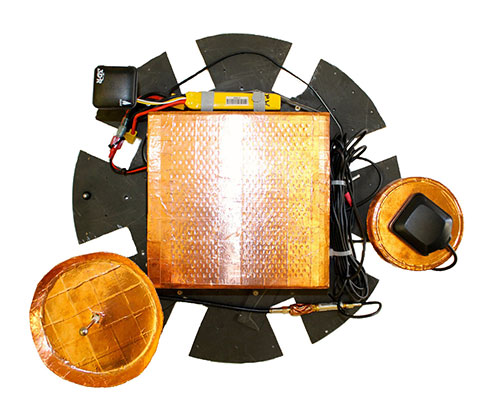
    The APNT payload prior to installation of the DME antenna. The copper shielding on the CPU and antennas can be clearly seen.
    The APNT payload prior to installation of the DME antenna. The copper shielding on the CPU and antennas can be clearly seen.

    Conclusions

    The development of the JAGER system contributes to U.S. preparation for a GPS jamming attack on civil aviation. While the first iteration described here is a significant improvement on previous jammer-hunting systems, future iterations of the JAGER UAV will be able to successfully navigate in a GPS-denied environment using alternative navigation signals including UAT and DME, and broadcast an accurate estimate of their position down to the ground.

    The use of an octocopter flight system gives speed, maneuverability and sensory perception that far exceed any ground-based tracking effort. A fully loaded top speed of 10 m/s and almost instantaneous direction changes allow for efficient hunting over an airport-sized area and the location of a GPS jammer to within 30 meters, within a 20-minute flight endurance.

    As the JAGER system can be entirely assembled from commercially available or open-source components and operates entirely autonomously, the system provides a low-cost, readily obtainable solution to the problem of GPS jamming. This means that it can be deployed quickly and is operable without extensive prior training.

    The integration of autopilot, APNT navigation and tracking systems also allows for comprehensive monitoring and control of the UAV from the ground. Telemetry and data links to the ground station provide real-time updates as to the craft’s position, the jammer’s believed location and the status of all systems and instruments running on the vehicle. Safety protocols implemented in the software ensure that there is no risk of collision with site buildings, vehicles or personnel.

    JAGER’s modular design gives operators extensive flexibility in situations that are capable of being successfully resolved by the system. The switching of equipment and software to allow the UAV to use GPS navigation to hunt a UAT or DME jammer, for example, could be effected in a matter of seconds.

    The JAGER system also provides a reliable test platform for any experiment that requires airborne operation. The exceptional stability of the airframe combined with extended flight time, high top speeds and pinpoint positioning lends the system to a wide variety of applications beyond jammer tracking, including network monitoring, atmospheric experiments and biological research.

    Manufacturers

    The JAGER UAV airframe is a S1000 octocopter by DJI Innovations, Shenzhen, China; the flight batteries are a 8000 mAh model by Hextronik, Dongguan, China; the autopilot hardware and GPS antenna is a Pixhawk by 3D Robotics, Inc., San Diego, California; the autopilot software is based on PX4 by Pixhawk.org. The JAGER navigation GPS is made by u-blox, and the receiver for the APNT clock is made by Trimble. The UAT hardware includes an ASR-2300 multichannel transceiver by Loctronix Corporation, Woodinville, Washington; the tracking hardware comprises a 2.4 GHz Yagi antenna from L-com, North Andover, Massachusetts; an RN-XV Wi-Fi module by Roving Networks, Chandler, Arizona; and an Odroid-U3 computer by Hardkernel Co., Gyeonggi, South Korea.


    James Spicer is pursuing concurrent bachelor’s and master’s degrees in aeronautics and astronautics at Stanford University.

    Adrien Perkins is a Ph.D. candidate in aeronautics and astronautics at the Stanford University GPS Laboratory. He received his undergraduate degree in mechanical aerospace engineering at Rutgers University.

    Louis Dressel is a graduate student at Stanford University. He received his undergraduate degree in aerospace engineering from Georgia Tech, with a minor in computer science.

    Mark James is a master’s student in aeronautics and astronautics at Stanford University.

    Yu-Hsuan Chen is a research associate at the Stanford GPS Laboratory. He received his Ph.D. in electrical engineering from National Cheng Kung University, Taiwan.

    Sherman Lo is a senior research engineer at the Stanford GPS Laboratory.

    David S. De Lorenzo is a principal research engineer at Polaris Wireless and a consulting research associate to the Stanford GPS Laboratory.

    Per Enge is a professor of aeronautics and astronautics at Stanford University, where he is the Vance D. and Arlene C. Coffman Professor in the School of Engineering. He directs the Stanford GPS Laboratory.
  • First GPS III Satellite Ready for Harsh Environment Testing

    First GPS III Satellite Ready for Harsh Environment Testing

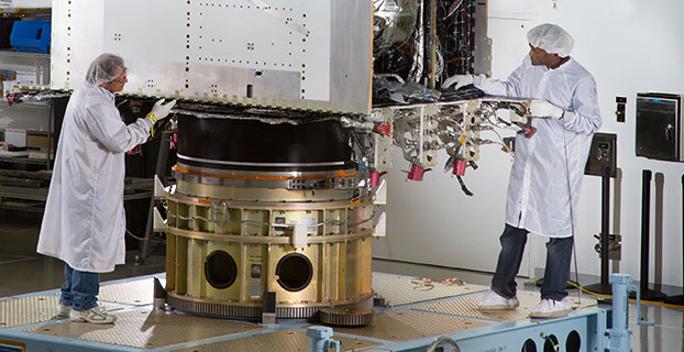
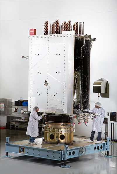
    In April, Lockheed Martin fully integrated the U.S. Air Force’s first next generation GPS III satellite at the company’s Denver-area satellite manufacturing facility.  The first in a design block of new, more powerful and accurate GPS satellites, GPS III Space Vehicle One is now preparing for system-level testing this summer.
    First Photo a GPS III Satellite: In April, Lockheed Martin fully integrated the U.S. Air Force’s first next-generation GPS III satellite. GPS III Space Vehicle One is now preparing for system-level testing this summer.

    Using a 10-ton crane, Lockheed Martin engineers and technicians gently lowered the system module of the U.S. Air Force’s first next generation GPS III satellite into place over its propulsion core, successfully integrating the two into one space vehicle.

    The April systems integration event brought together several major fully functional satellite components. The system module includes the navigation payload, which performs the primary positioning, navigation and timing mission. The functional bus contains sophisticated electronics that manage all satellite operations. The propulsion core allows the satellite to maneuver for operations on orbit.

    “The final integration of the first GPS III satellite is a major milestone for the GPS III program,” said Mark Stewart, vice president of Lockheed Martin’s Navigation Systems mission area. “This summer, SV 01 will begin Thermal Vacuum testing, where it will be subjected to simulated harsh space environments. Successful completion of this testing is critical as it will help validate our design and manufacturing processes for all follow-on GPS III satellites.”

    Lockheed Martin is under contract to build eight GPS III satellites at its GPS III Processing Facility near Denver, a factory specifically designed to streamline satellite production.

    GPS III space vehicle one (SV 01) is the first of a new, advanced GPS satellite design block for the Air Force. GPS III will deliver three times better accuracy, provide up to eight times improved anti-jamming capabilities, and extend spacecraft life to 15 years — 25 percent longer than the satellites launching today. GPS III’s new L1C civil signal also will make it the first GPS satellite interoperable with other international global navigation satellite systems.

    The GPS III team is led by the Global Positioning Systems Directorate at the U.S. Air Force Space and Missile Systems Center. Air Force Space Command’s 2nd Space Operations Squadron (2SOPS), based at Schriever Air Force Base, Colorado, manages and operates the GPS constellation for both civil and military users.

  • Septentrio Launches UAS Receiver, Software for Drone Market

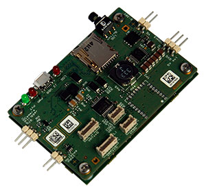
    The AsteRx-m UAS by Septentrio.
    The AsteRx-m UAS by Septentrio.

    Septentrio has launched the AsteRx-m UAS, an RTK-accurate GNSS receiver solution specially designed for the drone market. The AsteRx-m UAS provides high-accuracy GNSS positioning with low power consumption, according to Septentrio.

    The launch of the AsteRx-m UAS board is complemented by the release of GeoTagZ software suite. The GeoTagZ suite works with the UAS camera and image-processing solution to provide centimeter-accurate position tagging of images without the need for a real-time data link.

    The AsteRx-m UAS will be on display at booth #635 during AUVSI’s Unmanned Systems 2015, held May 4-7 at the Georgia World Congress Center in Atlanta.

    Despite being Septentrio’s smallest receiver, the AsteRx-m UAS provides consistent, robust and accurate positioning from to Septentrio’s in house GNSS+ algorithm technology. The receiver delivers cm-level accuracy at less than 600 mW with GPS and less than 700 mW with GLONASS. LOCK+ technology guarantees tracking under heavy usage and IONO+ guarantees no interference in challenging ionospheric conditions, Septentrio said.

    Integration into Any UAS. One of the key characteristics of AsteRx-m UAS and GeoTagZ is the seamless integration into any UAS. AsteRx-m UAS features standard connection functionality that directly connects to a UAS autopilot, such as Pixhawk and Ardupilot. The power comes directly from a number of power sources, including micro USB, a 9-30V external power supply or the vehicle power bus. GeoTagZ is available as a library of software to integrate into an UAS image-processing tool chain.

    “We want to make UAS-based data collection and processing extremely simple. AsteRx-m UAS and GeoTagZ do just that,” said Jan Leyssens, commercial product manager at Septentrio. “The GNSS board connects seamlessly to standard hardware and cameras used on a drone. Together with our software, we provide a data collection solution that provides cm-level accuracy without the need for ground control points or real-time data links, and that integrates effortlessly with an existing UAS image processing software solutions.”

  • IFEN’s v3.0 of SX3 GNSS Software Receiver Adds Functions

    IFEN has launched the latest software release, v3.0, for its SX3 GNSS Software Receiver Generation.

    The newly released software version 3.0 offers the following new features:

    • Real‐time P‐code generator and P‐code aiding for GPS L1/L2 cross‐correlation
    • Full dual‐antenna support for SX3 Black Edition
    • KML file output for Google Earth real‐time visualization
    • better performance through switch from 32-bit to 64-bit version
    • support of new SX3 RF front‐end with up to 12 IF streams

    IFEN’s SX3 multi‐GNSS software receiver now tracks all known and in future upcoming GNSS signals in view in real‐time on a standard laptop (up to 1,000 channels in parallel on a core i7 desktop PC). The included RF front‐end offers four RF frequency chains with 50 MHz bandwidth each, covering the entire GNSS L‐band spectrum.

    The USB 3.0 interface enables high‐speed data transfer with up to 8 bit quantization. Customers can fully concentrate on their applications instead of dealing with potentially obscure code when using open source. The professional support is specifically dedicated to sophisticated applications as well as SX3’s capability for additional customizations. This makes IFEN’s SX3 GNSS software receiver a powerful tool for research and development, IFEN said.

    In addition a dual‐antenna input RF front‐end (SX3 ‘Black Edition’) has been released in February 2015. This system can for example be used for heading determination, reflectometry and other applications requiring the synchronized input from two antennas.

  • GPS Data Show How Nepal Quake Disturbed Earth’s Upper Atmosphere

    GPS Data Show How Nepal Quake Disturbed Earth’s Upper Atmosphere

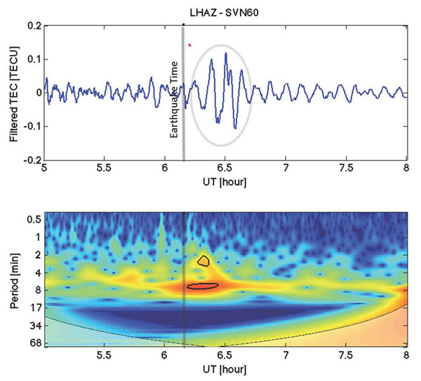
    The April 25 magnitude 7.8 earthquake in Nepal created waves of energy that penetrated into Earth’s upper atmosphere in the vicinity of Nepal, disturbing the distribution of electrons in the ionosphere. These disturbances were monitored using GPS signals received by a science-quality GPS receiver in Tibet, a neighboring region to Nepal.

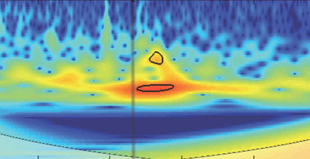
    The data show that after the initial earthquake rupture (indicated by the vertical black line on the graphic), it took about 21 minutes for the earthquake-generated ionospheric disturbance to reach a GPS station (LHAZ) about 400 miles (640 kilometers) away from the epicenter in Lhasa, Tibet, China.

    Image Credit: NASA/JPL/Ionosphere Natural Hazards Team
    Image Credit: NASA/JPL/Ionosphere Natural Hazards Team

    The disturbance measurements, known as vertical total electron content (VTEC) (depicted in blue in the upper panel), have been filtered using processing software developed by NASA’s Jet Propulsion Laboratory in Pasadena, Calif., to show wave-like disturbances (circled in red) in the distribution of electrons in the ionosphere. The waves have periods of between two and eight minutes in length. The disturbance measurements following the earthquake rupture are circled in black in the lower panel. The colors represent the relative strengths of the earthquake-induced ionospheric disturbances as captured by the GPS signals, with red being high and blue being low.

    Attila Komjathy, a principal  investigator of the Ionospheric and Atmospheric Remote Sensing group at JPL and adjunct professor at the University of New Brunswick, is leading this effort. Komjathy is also a GPS World annual award winner and named a Fellow of the Institute of Navigation in January.

    The LHAZ GPS station is hosted at the Tibet Autonomous Regional Bureau of Surveying and Mapping Institute. The site collects both GPS and GLONASS (the Russian global navigation satellite system) data at a rate of 1 Hertz and is part of the International GPS Service (IGS).

    Scientists study ionosphere-based measurements caused by natural hazards such as earthquakes, volcanic eruptions and tsunamis to better understand wave propagation in the upper atmosphere.The ionosphere is a region of Earth’s upper atmosphere located from about 37 miles (60 kilometers) to 621 miles (1,000 kilometers) above Earth’s surface.

    The disturbances caused by earthquakes help scientists develop new first-principle-based wave propagation models. These models may become part of future early warning systems for tsunamis and other difficult-to-detect natural hazards.

    The data is available on this FTP site.

  • The System: All Systems Go, with a Spring into Space

    Planet Earth gained five new navigation satellites in late March, for four satellite systems.

    GPS. The U.S. Air Force’s ninth GPS Block IIF satellite (GPS IIF-9) launched on March 25 from Cape Canaveral, Fla. The IIF-9 rode aboard a Delta IV rocket, the workhorse of the GPS fleet for successful launches. The satellite was declared operational on April 21.

    “Many thought the Delta IV and GPS days were long gone, but the recent questions concerning reliable and proven launch vehicles have brought them back online, so to speak,” said GPS World Defense Editor Don Jewell. “The 20-year milestone for GPS space vehicles on orbit that occurred on April 27 translates to approximately 500 orbital years just for the IIR and IIF constellations alone. The IIAs may account for that many orbital hours as well.

    “This is by far the most successful launch record ever put together by any nation or government. No other space-faring nation even comes close. The U.S. Air Force and all the players should be proud of all these records and more, plus we have one more GPS asset on orbit, providing GPS signals to the world and all they enable, courtesy of the USAF.”

    Galileo. Two days later, March 27, a duo of Galileo satellites was successfully launched from Europe’s Spaceport in French Guiana. The seventh and eighth Galileo satellites rode aboard a Soyuz ST-B rocket. Both are in their planned orbits.

    IRNSS. The next day, March 28, the fourth satellite (IRNSS-1D) of  the IRNSS satellite navigation constellation was launched onboard PSLV-C27, and reached its orbital slot April 9. The Polar Satellite Launch Vehicle blasted off from the Satish Dhawan Space Center on India’s east coast, in the 28th consecutive successful PSLV mission.

    BeiDou. On March 30, China launched the first of a new generation of navigation satellites, BeiDou-3 M1, for its BeiDou constellation. BeiDou-3 M1 is the first of 17 next-generation Beidou navigation satellites. It will have a new navigation signal system with inter-satellite links and other tests to verify the satellite navigation system. The new series of satellites is expected to mark an advancement in the completion of Beidou Phase III several years ahead of schedule, by as soon as 2017 rather than 2020.

    GLONASS. Not making the March launch cut, GLONASS kept its hat in the orbit ring, so to speak, by issuing some far-sighted predictions. Nicholas Testoyedov, CEO of Information Satellite Systems Reshetnev, said that the first GLONASS-K2 spacecraft will be launched into orbit in 2018. “New code division (CDMA) signals will be emitted, so it will provide more accurate positioning for users.”

    The GLONASS budget for 2015 will be cut by more than 5 billion rubles, a drop of more than 10 percent. GLONASS is also suffering through an embezzlement scandal, related to construction of a new ground control center.

    Galileo's worldwide ground segment as of March 2013.
    Galileo’s worldwide ground segment as of March 2013.

    Galileo Ground Upgrade

    On April 9, the European Space Agency announced completion of a full-scale hardware and software migration to version V2.0 of its global Ground Mission Segment providing all Galileo navigation messages. The Ground Mission Segment was turned off Jan. 26, allowing the migration to take place over the month of February. March was taken up with detailed checking by operations and system, concluding in a final check on March 31 to validate the successful migration.

    “The upgrade has provided better overall performance and availability, along with improved robustness, security and operability,” explained Martin Hollreiser, overseeing mission segment development for ESA, with Thales Alenia Space France as prime contractor. “An overall 25 percent performance improvement is confirmed.

    “Three new sensor stations, Kiruna, Ascension and Azores — used to monitor the satellite navigation signals — were added to the operations chain, as well as a new uplink station in Papeete, to uplink corrections incorporated in the navigation message to the satellites for broadcast to the users.”

    The Ground Mission Segment at its core is determining the exact satellite orbits and synchronizing all the satellite and terrestrial elements of that clock: the relevant control center is linked to a global network of ground stations (sensor and uplink stations). The Galileo signals currently undergo technical testing, with early services for the public projected for 2016. “A further update is foreseen for the end of this year,” Hollreiser added, although this will occur with no interruption of services.

    GPS Glitch Dates from 2011

    On April 15, the U.S. Air Force GPS Directorate said data analysis shows that a technical error affecting some GPS IIF satellites first appeared in 2011. The error affects the way the ground control system builds and uploads messages transmitted by the satellites, but does not affect the accuracy of GPS signals. It involves the ground-based software used to index messages. “A GPS message indexing issue was recently identified that affects a limited number of active GPS IIF satellites, but does not degrade the accuracy of the GPS signal received by users around the globe. The result is an occasional broadcast not in accordance with U.S. technical specifications. ”

  • The Business — May 2015

    The Business section from the May 2015 issue. Download the PDF.

    Includes:

    • Furuno Receiver Adopted for Parrot Bebop
    • NovAtel Launches Relay RTK Radio Module
    • Phantom 3 Has Indoor Positioning
    • SBG Systems Selects Septentrio AsteRx4 for Apogee Series
    • Hemisphere GNSS Offers RTK-Capable Antenna
    • Applanix Offers Three New Marine Products
    • Cobham Aeroflex Tester Used for ADS-B
    • Briefs
    • Events
  • Expert Advice: Sensor Fusion for Highly Automated Driving

    High-Precision GNSS Needs Help for Continuous Localization Reliability

    By Siamak Akhlaghi

    Automotive safety and comfort functions, known as Advanced Driver Assistance Systems (ADAS), have become an essential part of modern vehicles. These functions assist drivers in the driving process, providing capabilities such as adaptive cruise control or highway driving mode. To achieve a desired level of performance, the position of the vehicle must be known. Precise positioning supports the vehicle’s systems with planning, executing and monitoring of a particular maneuver.

    Position determination, or localization, is the estimation of the location, heading, velocity and acceleration of a vehicle with respect to a fixed coordinate system. High-precision GNSS provides an excellent, worldwide, absolute position reference for localization. However, GNSS technology alone has limitations that must be overcome to make it suitable for use in autonomous systems. For instance, GNSS signals may become blocked or lost due to: obstructions such as in urban canyon or tunnels; multipath, where signals are reflected off the vehicle body; or signal interference from other RF signal sources.

    Siamak Akhlaghi
    Siamak Akhlaghi

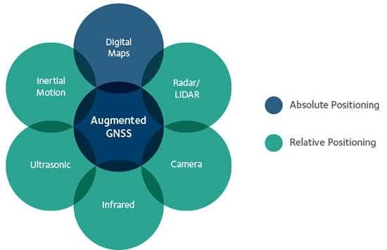
    GNSS correction data and data from other sensors on the vehicle can be used to improve the accuracy and reliability of the vehicle localization solution both globally and with respect to the local environment. To achieve the localization performance, accuracy and integrity required for autonomous vehicles, a multi-system, sensor fusion approach seems to be the most promising. Localization systems will require absolute positioning references like precision GNSS as well as local or relative positioning inputs from inertial sensors, odometers, radar, LiDAR, cameras, infrared and ultrasound sensors. It is clear that no single technology will make highly automated driving possible. Rather, the fusion of the entire vehicle’s sensing technologies will provide the localization accuracy and reliability required.

    Achieving Accuracy and Reliability with GNSS

    GNSS has revolutionized localization in many applications, from precision survey to agricultural guidance. For autonomous driving applications, localization accuracy of 30 centimeters (cm) or less is required. The single-frequency, auto-grade GNSS receivers that have been used in vehicles up to now cannot achieve this level of accuracy. Multi-frequency GNSS receivers utilizing Precise Point Positioning (PPP) correction techniques can achieve accuracies better than 10 cm. PPP algorithms combine GNSS satellite clock and orbit correction data from a global reference station network with high precision GNSS receiver satellite observations to yield robust sub-decimeter positioning without the need for local base stations. Since the PPP corrections can be delivered via satellite, the solution is ideal for highly automated driving where communications infrastructure is costly and in some areas may not be available. Recent advances in PPP techniques provide robust positioning and the ability to quickly regain full accuracy following a temporary loss of GNSS signals, for instance under foliage or highway overpasses.

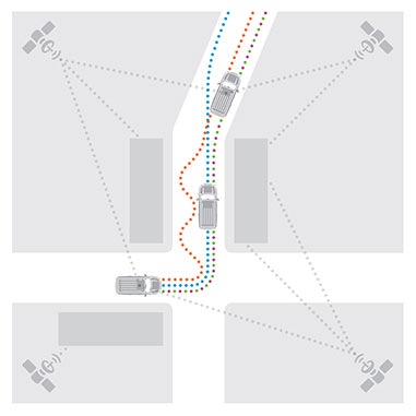
    Figure 1. High precision / localization with sensor fusion.
    Figure 1. High-precision / localization with sensor fusion.

    Sensor Fusion

    Occasional instantaneous irregularities and temporary outages of GNSS can be compensated for by incorporating measurements of the vehicle motion from inertial sensors mounted in the vehicle. An advantage of a tightly coupled GNSS-inertial solution is that the low frequency errors inherent to inertial sensors can be compensated for and removed from the solution. As a result, sensor fusion algorithms provide a highly robust and stable localization solution at data rates as high as 200 Hz. Other sensors in the vehicle, such as odometers, cameras or LiDAR, can also give information about the relative motion of the vehicle and can add to the redundancy, reliability and stability of the localization solution.

    Figure 2. With a tightly coupled GNSS-inertial solution, low-frequency errors can be removed from the localization solution. The brown dots are the GNSS solution, the blue dots are the inertial solution, and the combined colors represent the tightly coupled solution.
    Figure 2. With a tightly coupled GNSS-inertial solution, low-frequency errors can be removed from the localization solution. The brown dots are the GNSS solution, the blue dots are the inertial solution, and the combined colors represent the tightly coupled solution.

    High-Precision GNSS Antenna

    Antennas play a critical role in achieving precise localization with GNSS. While GNSS antenna requirements differ depending on the application, ideally the antenna should receive only signals above the horizon, have a known and stable phase center that is co-located with the geometrical center of the antenna, and have perfect circular polarization characteristics to maximize the reception of the incoming signals. Highly automated driving applications demand high performance as well as compact size and strong interference rejection. Achieving the required performance amidst these challenging constraints will require innovative new GNSS antenna designs.

    Autonomous driving will be a reality in the not-too-distant future. Innovation in the suite of sensors and fusion algorithms used for solving the localization challenge will be paramount to making safe and reliable autonomous vehicles. Further, innovation developed for automotive autonomy will support new autonomous vehicle applications in other segments.

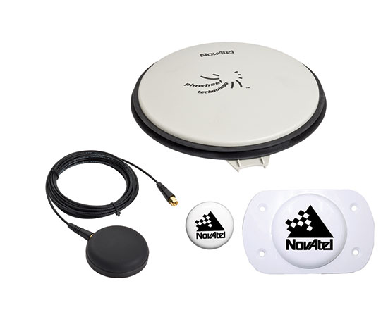
    High-precision antennas are key.
    High-precision antennas are key.

    Siamak Akhlaghi is segment manager for Autonomous Systems at NovAtel. He has 20 years of professional experience working for high-tech sectors with broad experience in inertial sensors and navigation systems.

  • TomTom’s New Devices Have Lifetime Maps, Speed Cameras

    TomTom’s New Devices Have Lifetime Maps, Speed Cameras

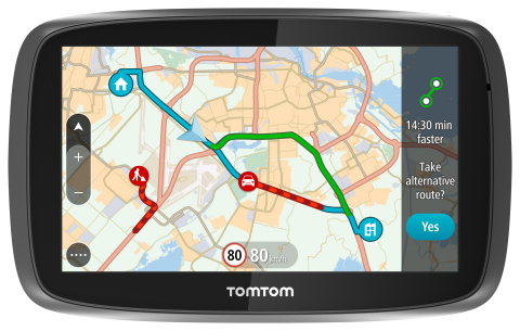
    TomTom is introducing Lifetime World Maps and Lifetime Speed Cameras to drivers with the launch of four new TomTom navigation devices.
    TomTom is introducing Lifetime World Maps and Lifetime Speed Cameras to drivers with the launch of four new TomTom navigation devices.

    TomTom is introducing Lifetime World Maps and Lifetime Speed Cameras to drivers with the launch of new TomTom navigation devices. Lifetime World Maps allow people to drive with maps from around the world at no extra cost, for the lifetime of their TomTom GO device2. Lifetime Speed Cameras let drivers know the locations of all speed cameras — both fixed and mobile, also for the lifetime of the device.

    The TomTom GO 510, 610, 5100 and 6100 feature a fully interactive screen to pinch, zoom and swipe — as well as a rich user interface, simplified user interaction, 3D Maps and a Click & Go mount. Drivers can also choose between a 5-inch or a 6-inch screen size, TomTom said. The new TomTom GO devices also include “Drive Home” and “Drive to Work” buttons in the main menu, for faster, simpler navigation.

    TomTom GO devices combine real-time traffic information with routing technology, to always offer drivers the fastest route available. TomTom Traffic covers all mapped roads and combines data from millions of data sources, from all over the world, to deliver traffic information so accurate that, with each new update, it can pinpoint the start and end of a traffic jam, precisely, down to 10 meters.

    “With the addition of Lifetime World Maps and Lifetime Speed Cameras to our new TomTom GO devices, we’re offering the most comprehensive package to drivers that we’ve ever launched,” said Corinne Vigreux, co-founder and managing director, TomTom Consumer. “Our aim is to help you avoid the jams, getting to your destination faster, wherever in the world you might be.”

    Lifetime TomTom Traffic is available via a smartphone connection on the TomTom GO 510 and 610. The TomTom GO 5100 and 6100 offer Lifetime TomTom Traffic via a built-in SIM with unlimited data and roaming at no extra cost.

    The new TomTom navigation devices are compatible with TomTom MyDrive4. For the first time, drivers can use their smartphone, tablet or PC to review real-time traffic information, plan routes, and send destinations to their TomTom GO, before they get in the car. Previously launched TomTom GO devices5 are also compatible with MyDrive though a simple software update. Find out more about TomTom MyDrive here.

    The new TomTom GO devices are now available online and in-store from €199.95.

  • Topcon GNSS Network Expands to Latin America

    Topcon GNSS Network Expands to Latin America

    Photo: Topcon GNSS

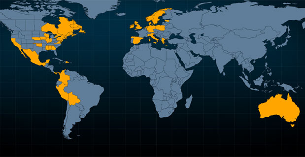
    Topcon Positioning Group is expanding the TopNETlive GNSS reference station network into Latin America. In conjunction with hosting partners, new service will be provided in Mexico, Peru, the Dominican Republic, Bolivia, Guatemala, Colombia and Panama.

    TopNETlive is designed to deliver high-accuracy GNSS correction data to rovers for surveying, construction, GIS mapping and agricultural applications.

    Partners in the Latin America expansion include TTQ of Monterrey, Geomatic Instruments Corporation, Caribbean Positioning System, Mertind, GYFSA and GeoSystem.

    “The growth of the network into Latin America through these strong partnerships clearly demonstrates the Topcon commitment to grow TopNETlive and provide quality service to more positioning professionals globally,” said Jonathan Ball, senior manager for the Topcon network business. “Our hosting partners provide outstanding support, training and service to their customers and the addition of the TopNETlive reference stations will allow them to expand their operations by offering real-time network correction data.”

    Topcon dealers will host TopNETlive throughout the various regions, which include: TTQ of Monterrey for Mexico, Geomatic Instruments Corporation in the Peruvian market, Caribbean Positioning System in the Dominican Republic area, Mertind Ltda in Bolivia, GYFSA in Guatemala, and Columbia-based GeoSystem will host the network throughout Colombia and Panama.


  • KVH Receives $1.5M Order for TACNAV Systems

    KVH Receives $1.5M Order for TACNAV Systems

    Credit: U.S. Armed Services.
    Credit: U.S. Armed Services.

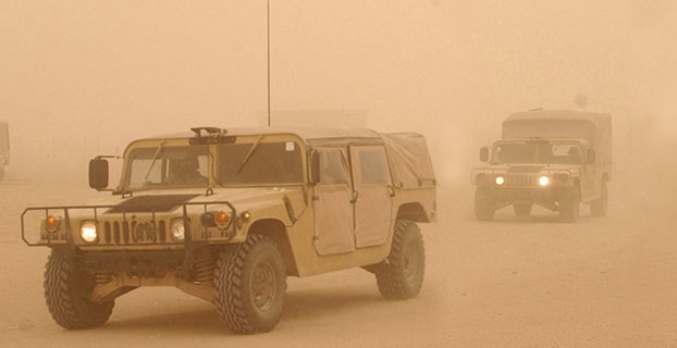
    KVH Industries Inc. has received a $1.5 million contract for the delivery of tactical navigation systems for use by an international military customer in an armored vehicle application. A variant of KVH’s TACNAV TLS and TACNAV Light, the system is designed to help military vehicle crews maintain 100% situational awareness. The hardware shipments for this order are expected to be made in 2015. Program management and engineering services will be provided as part of this order.

    “KVH’s TACNAV navigation solution is an important tool for U.S. and allied warfighters, providing precision navigation as well as coordination of vehicles in critical situations,” said Dan Conway, executive vice president of KVH’s guidance and stabilization group. “The system serves as a crucial resource for navigation and battle management, keeping soldiers safe and out of harm’s way wherever they travel. This new order reaffirms the value of KVH’s TACNAV products for international militaries, and adds to our backlog for the year.”

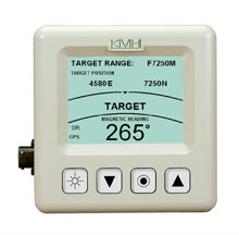
    The TACNAV TLS by KVH Industries.
    The TACNAV TLS by KVH Industries.

    All of KVH’s TACNAV military vehicle navigation systems provide unjammable precision navigation, heading, and pointing data for vehicle drivers, crews and commanders, KVH Industries said. TACNAV can also serve as a heading and position source for situational awareness.

    The TACNAV system ordered combines characteristics of TACNAV TLS and TACNAV Light, and features a compact design, continuous heading and pointing data output, and a flexible architecture that allows it to function as either a standalone navigation module or as the heart of an expanded, multifunctional TACNAV system. The system is designed to integrate with battle management systems and is a vital component for effective battlefield management, KVH Industries said.

    TACNAV systems are in use by the U.S. Army and Marine Corps, as well as many allied customers including Canada, Sweden, Great Britain, France, Germany, Spain, Egypt, Botswana, Australia, New Zealand, Saudi Arabia, Taiwan, Romania, Poland, Turkey, Malaysia, Switzerland, South Korea, Singapore, Brazil and Italy.

  • Protecting Position in Critical Operations

    Jamming Signals Criminal Activity in Intermodal Ports

    By Logan Scott

    More than 25 million containers pass through U.S. intermodal ports every year, with port operations valued at more than $1 billion per day. Measured in 20-foot equivalent units (TEU), the World Bank reports that worldwide, more than 600 million TEU passed through intermodal ports in 2012: 155 million through Chinese ports, 95 million through the EU ports and 43 million through U.S. ports.

    The Port of Long Beach alone handled 6,820,806 TEU in 2014. GPS is a central component of automated port operations, but because GPS is widely used in asset tracking and monitoring, it has also become a target for denial-of-service attacks. If we look to the history of computer security, the initial attacks were mostly nuisances, but as criminals figured out how to monetize attacks, the attacks became more damaging, more sophisticated and more profitable.

    In January, the U.S. Coast Guard held a public meeting on Maritime Cybersecurity Standards at Department of Transportation headquarters in Washington, D.C. Brett Rouzer, chief of Maritime Critical Infrastructure and Key Resources Protection, Coast Guard Cyber Command, described how a major East Coast intermodal shipping facility was degraded by a GPS disruption for more than seven hours. Two ship-to-shore cranes ceased operation due to loss of position, and two others were degraded. Ports are highly automated; ship-to-shore cranes are just one of the container-handling systems critically reliant on GPS. Fully automated ports providing services for unmanned container ships, trucks and trains lie within the realm of feasibility in the near future.

    Rouzer did not specify the motivates for the disruption, how the attack was mounted, or if the shipping facility was even the intended target of the attack (I suspect it was not). Jamming is not a highly selective process, and it can affect numerous unintended targets.

    In June 2014, I reported to the PNT Advisory Board on how every third or fourth truck on Highway 30B near Portland (Oregon) International Airport was radiating at or near the GPS L1 frequency. This highway leads to several nearby Port of Portland intermodal terminals west of the airport. The Federal Bureau of Investigation recently reported that “In 46 reported incidents, the thieves placed one or more GPS jammers in cargo containers with stolen automobiles” (italics mine). High-end automobiles command premium prices in foreign markets and are stolen and shipped out of the country within hours, usually via intermodal container. Active jammers can affect not only the automobile’s GPS tracker, but also trackers on other containers, ship’s navigation systems, straddle carriers and ship-to-shore cranes. Again, jamming is not selective.

    Of particular note as cited above, criminals are beginning to use multiple jammers. Car theft rings are not unique in this. According to the Pharmaceutical Cargo Security Coalition in July 2014, “a tractor and trailer hauling $2 million worth of pharmaceutical products was stolen from a truck stop in Cartersville, Georgia, with the thieves deploying two separate GSM jammers.” The criminal’s motivation is that tracking devices can be hard to find and disable; just because you found one doesn’t mean that there isn’t another. The use of multiple jammers in criminal enterprise is indicative of a threat escalation where bad actors are seeking higher effect. This could lead to higher jamming powers and so on; and also more collateral damage.

    Response

    What is a correct and measured response to threats against navigation and timing? The key is to be on the lookout for emerging threats and to have a flexible response. Early detection usually yields a more effective and lower cost response; witness Ebola and ISIS. Following a public health model would seem to offer better prospects for protecting access to PNT. To this end, I would argue that situational awareness is the first important step.

    One of the most striking comments that Sarah Mahmood (DHS) made at last June’s PNT Advisory Board meeting was about how backup systems are often not activated or used because the GPS receiver fails to recognize that there is a problem. As we move towards resilient PNT architectures, one of the most critical needs is to be able to distinguish good signals from bad signals and act accordingly.

    Most GNSS receivers already have fairly advanced jamming detection capabilities by virtue of having an automatic gain control. Sudden changes in precorrelation input power levels are not normal and can indicate jamming or RF spoofing. Many GNSS receivers, particularly those that go into embedded mobile applications, also have sophisticated spectrum- and temporal-analysis capabilities, used mainly for diagnostic purposes in looking for interference sources from other components of the device. This same capability can be used in detecting and fingerprinting jammers. We already have the smoke alarms; we must amplify their use and visibility to the wider community of GNSS users and beyond.

    Detection

    One notable aspect of the port incident was the duration: more than seven hours. Rapidly finding and disabling the jammer was clearly a problem in this case. The old adage is that to find a stationary source (jammer) you need to be moving, and to find a moving source, you need to be stationary. Trucks and trains entering or leaving a port all pass through gates that can act as a simple chokepoint for detecting and finding active jammers. Properly hardened ship-to-shore cranes and straddle carriers can also act as a chokepoint. Straddle carriers used in moving containers around the yard and between modes could be very good at finding stationary jammers.

    There are numerous relatively low-cost approaches for finding jammers in support of enforcement actions. One additional point: law enforcement officials need to be better educated as to why they should be interested in jammers; jammers point towards a crime much like smoke points to a fire.

    Given the economic criticality of port operations and the concentration of assets (and asset trackers), we may see increased incidence of GPS disruptions. The situation is not critical yet, but it does bear watching. If jamming events increase or it takes too long to find and disable jammers, improved operational resilience will be needed.

    Inertial measurement units are already used in many critical applications, but they don’t offer long-duration capability. They drift. Using adaptive arrays in critical equipments is another possibility, but they are not a panacea. Adaptive arrays are physically large, and standard null-steering approaches are not compatible with RTK processing. Precise positioning systems based on GNSS require specialized antenna-receiver designs to achieve a high level of jam resistance.

    While I strongly believe eLoran is an urgently needed augmentation for resilient wide area navigation, it is not capable of the centimeter-level precision required for machine control, for example ship-to-shore cranes and straddle carriers.

    High-precision local-area positioning systems based on optical systems, RFID and/or Locata-style systems may be the best approach for creating a defense in depth.

    And then there is the cybersecurity question, which I will leave for another day.


    Note: A video of the Coast Guard meeting is on YouTube. Rouzer’s talk starts at 36:30, with the port jamming incident mentioned at 48:51.


    Logan Scott has 35 years of military and civil GPS systems engineering experience. He is a consultant specializing in radio frequency signal processing and waveform design. At Texas Instruments, he pioneered approaches for building high-performance, jamming-resistant digital receivers. He is a co-founder of Lonestar Aerospace, an advanced decision analytics company in Texas. Logan is a Fellow of the Institute of Navigation and holds 37 U.S. patents.