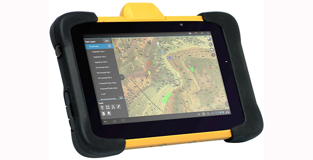
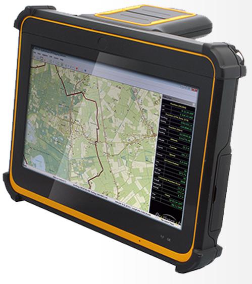
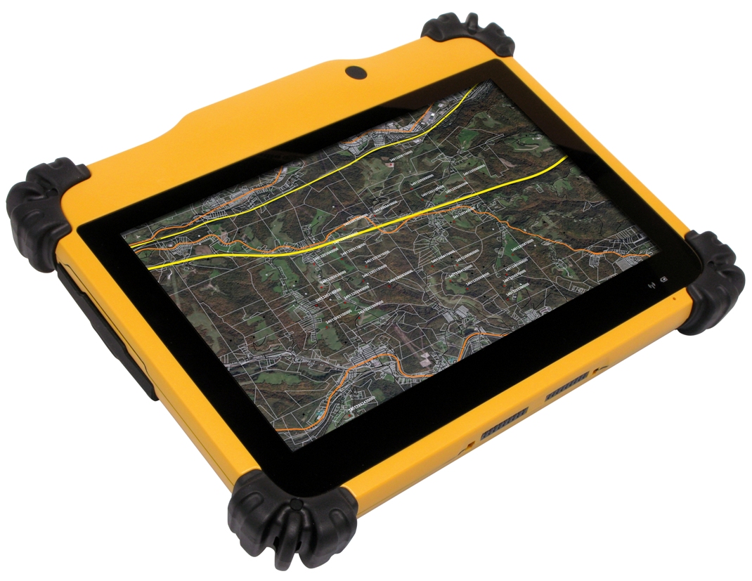
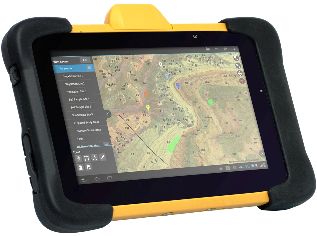
DT Research Inc. has launched a new line of rugged tablets with the GNSS modules for surveying and mapping applications. The DT391GS, DT395GS and DT307GS rugged tablets feature integrated high-accuracy GNSS receiver modules with built-in antenna for seamless data capture, the company said.
Built to travel and provide reliable operations in the real world, the tablets are designed for field work in mapping, geographic information systems (GIS), and accurate synchronization, tracking and networking.
The DT391GS combines a 9-inch sunlight-readable, capacitive touch display with an energy-efficient Intel dual-core processor in a compact, durable package. With the high-accuracy GNSS module options (Hemisphere or Trimble), the foldable antenna, and Windows or Android operating system. The DT391GS also offers protection in demanding environments with IP65 and MIL-STD-810G ratings for dust and water, and shock and vibration resistance.
The DT395GS tablet.
The DT395GS offers a 9-inch sunlight-readable capacitive touch screen, an energy efficient Intel dual-core processor, and a choice of Windows or Android operating systems. The GNSS positioning module has u-blox GNSS module. The IP65 rating, and military-standard MILSTD-810G and MIL-STD-461F ratings, as well as wide temperature range, make the DT395GS reliable even in harsh, mission-critical environments.
The DT307GS GNSS tablet features a brilliant 7-inch capacitive touch screen and a quad-core, energy efficient processor with a built-in, high-accuracy u-blox GNSS module. The size and weight of the DT307GS make this tablet portable for long-term handling in the field, DT Research said.
The DT307GS tablet
All of the DT Research Rugged GS Tablets offer hot-swappable batteries for continuous operation, enabling real-time project efficiency between staff in the field and in the office. With wireless support for Bluetooth, 802.11, WCDMA and HSPA+ connectivity and optional GSM networking, the tablets keep staff connected from any location.
The DT391GS and DT395GS have Trusted Processing Module (TPM) encryption for security support, and a choice of Microsoft Windows Embedded Standard 7 or 7 Professional, or Android operating system making these tablets flexible to integrate with existing applications.
An optional 5-megapixel camera offers another data capture tool to record visual information, and an optional 3G cellular data module provides data connectivity for navigation and real-time data transfer, DT Research said.
The DT391GS, DT395GS, and DT307GS are available now, form more information, contact DT Research at [email protected].
Tandem Expansion Fund, a Canadian growth-equity investor, has acquired a majority interest in Averna, a developer of test solutions and services for communications and electronics device-makers, according to a news release from Averna. The transaction provides Averna with the financial resources to “accelerate organic and strategic growth as well as to expand its international presence,” the release said.
Founded in 1999, Averna is a test engineering company that provides test expertise and solutions for tier-one clients in wide-ranging industries around the world, including aerospace and defense, telecom infrastructures, automotive and transportation, consumer electronics and life sciences. Averna has more than 300 employees and offices in 5 countries.
“This is a new chapter for Averna and we are proud to have the support of these strategic and respected partners who share our vision and values,” said André Gareau, Averna’s president and CEO. “Averna is a Montreal-based success story and it is important for us to continue hiring the best local talents. This investment will help us extend our leadership position in each of our key industries as well as continue growing the company locally and internationally.”
“Averna’s unique expertise in test, growing base of customers across the globe, excellent management team and portfolio of solutions position the company at the forefront of the electronic test and quality market,” said André Gauthier, managing partner at Tandem Expansion Fund. “With this investment, Tandem is providing solid support to Averna in the next phase of its development.”
Averna has offices around the world as well as a network of partners such as JOT Automation, Keysight Technologies, and National Instruments. Incorporated in 1999, Averna is a Best in Test award winner and has been honored as one of the Deloitte Fast 500 fastest-growing technology companies in North America.
The U.S. Air Force’s ninth GPS Block IIF satellite (GPS IIF-9) launched on March 25 aboard a United Launch Alliance (ULA) Delta IV rocket, which has been the workhorse of the GPS fleet for successful launches. ULA provided this video showing highlights of the launch.
The first GLONASS-K2 spacecraft will be launched into orbit in 2018, said Nicholas Testoyedov, the CEO of Information Satellite Systems Reshetnev, as reported by the Assotsiatsiya GLONASS/GNSS Forum.
“In 2018, we are preparing to launch the first satellite of the series GLONASS-K2,” Testoyedov said. “This satellite has advanced features. In the development of the navigation functions, new code division signals will be emitted, so it will provide more accurate positioning for users and more accurate tethering in those systems where important accurate time reference is required, such as in computer systems, connected devices, and so on.”
Testoyedov added that the GLONASS-K2 satellite will have equipment installed that makes it compatible with the international search and rescue system Cospas–Sarsat.
Budget Cuts. The budget of the GLONASS federal target program (FTP) for 2015 will be cut by more than 5 billion rubles, according to Russian news reports. After spending cuts, the budget for the current year will amount to 42.5 billion rubles, a cut of more than 10 percent, which is the average size of cuts for the entire “Space activities of Russia for 2013-2020” budget group.
GPSTrackIt.com has added the ability to allow vehicles in Fleet Manager, its fleet and mobile workforce management system, to simultaneously belong to multiple groups. The feature enables groups to be “nested,” expanding the reporting and alerting capabilities of Fleet Manager.
“A vehicle belonging to more than a single group now appears in the list for each group selected,” said Eddie Bermudez, GPSTrackIt.com’s product development manager. “Units in two groups will appear twice, once in each group.”
Vehicle membership in multiple groups can be seen in the following changes to Fleet Manager:
The Vehicle Status page has been augmented with a selection/filter list for groups.
On the Map page, the information bubble for the unit displays all group tags.
The Analytics Dashboard can now compare two groups containing the same unit.
Scheduled Reports can be run using multiple groups.
“This enables the creation of ‘nested’ or vehicle sub-groups,” Bermudez said. “Say there are sales teams at local offices. Each office has a ‘sales team’ vehicle group. But the regional sales manager is responsible for five locations, so the vehicles are also in the ‘regional sales team’ group.”
Analysis of new Galileo signals at an experimental ground-based augmentation system (GBAS) compares noise and multipath in their performance to GPS L1 and L5. Raw noise and multipath level of the Galileo signals is shown to be smaller than those of GPS. Even after smoothing, Galileo signals perform somewhat better than GPS and are less sensitive to the smoothing time constant.
By Mihaela-Simona Circiu, Michael Felux, German Aerospace Center (DLR), and Sam Pullen, Stanford University
Several ground-based augmentation system (GBAS) stations have become operational in recent years and are used on a regular basis for approach guidance. These include airports at Sydney, Malaga, Frankfurt and Zurich. These stations are so-called GBAS Approach Service Type C (GAST C) stations and support approaches only under CAT-I weather conditions; that is, with a certain minimum visibility. Standards for stations supporting CAT-II/III operations (low visibility or automatic landing, called GAST D), are expected to be agreed upon by the International Civil Aviation Organization (ICAO) later this year. Stations could be commercially available as soon as 2018.
However, for both GAST C and D, the availability of the GBAS approach service can be significantly reduced under active ionospheric conditions. One potential solution is the use of two frequencies and multiple constellations in order to be able to correct for ionospheric impacts, detect and remove any compromised satellites, and improve the overall satellite geometry (and thus the availability) of the system.
A new multi-frequency and multi-constellation (MFMC) GBAS will have different potential error sources and failure modes that have to be considered and bounded. Thus, all performance and integrity assumptions of the existing single-frequency GBAS must be carefully reviewed before they can be applied to an MFMC system. A central element for ensuring the integrity of the estimated position solution is the calculation of protection levels. This is done by modeling all disturbances to the navigation signals in a conservative way and then estimating a bound on the resulting positioning errors that is valid at an allocated integrity risk probability.
One of the parameters that is different for the new signals and must be recharacterized is the residual uncertainty attributed to the corrections from the ground system (σpr_gnd). A method to assess the contribution of residual noise and multipath is by evaluating the B-values in GBAS, which give an estimate of the error contribution from a single reference receiver to a broadcast correction. Independent data samples over at least one day (for GPS) are collected and sorted by elevation angle. Then the mean and standard deviations for each elevation bin are determined.
Here, we evaluate the E1 and E5a signals broadcast by the operational Galileo satellites now in orbit. In the same manner as we did for GPS L5 in earlier research, we determine the σpr_gnd values for these Galileo signals. As for GPS L5, results show a lower level of noise and multipath in unsmoothed pseudorange measurements compared to GPS L1 C/A code.
DLR GBAS Facility
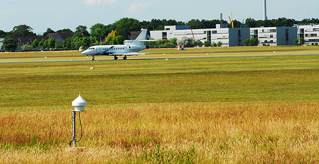
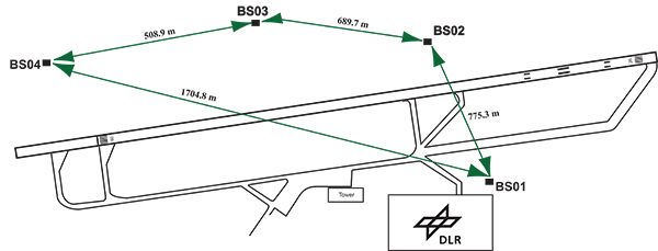
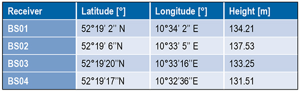
DLR has set up a GBAS prototype at the research airport in Braunschweig (ICAO identifier EDVE) near the DLR research facility there. This ground station has recently been updated and now consists of four GNSS receivers connected to choke ring antennas, which are mounted at heights between 2.5 meters and 7.5 meters above equipment shelters. All four receivers are capable of tracking GPS L5 (in addition to GPS L1 and L2 semi-codeless) and Galileo E1 and E5a signals. Figure 1 gives an overview of the current ground station layout, and Table 1 gives the coordinates of the antennas.
Figure 1. DLR ground facility near Braunschweig Airport, also shown in opening photo at left.Table 1. Ground receiver antenna coordinates.
Smoothing Techniques
The GBAS system corrects for the combined effects of multiple sources of measurement errors that are highly correlated between reference receivers and users, such as satellite clock, ephemeris error, ionospheric delay error, and tropospheric delay error, through the differential corrections broadcast by the GBAS ground subsystem. However, uncorrelated errors such as multipath and receiver noise can make a significant contribution to the remaining differential error. Multipath errors are introduced by the satellite signal reaching the antenna via both the direct path from the satellites and from other paths due to reflection. These errors affect both the ground and the airborne receivers, but are different at each and do not cancel out when differential corrections are applied.
To reduce these errors, GBAS performs carrier smoothing. Smoothing makes use of the less noisy but ambiguous carrier-phase measurements to suppress the noise and multipath from the noisy but unambiguous code measurements.
The current GBAS architecture is based on single-frequency GPS L1 C/A code measurements only. Single-frequency carrier smoothing reduces noise and multipath, but ionospheric disturbances can cause significant differential errors when the ground station and the airborne user are affected by different conditions. With the new available satellites (GPS Block IIF and Galileo) broadcasting in an additional aeronautical band (L5 / E5), this second frequency could be used in GBAS to overcome many current limitations of the single-frequency system.
Dual-frequency techniques have been investigated in previous work. Two dual-frequency smoothing algorithms, Divergence Free (Dfree) and Ionosphere Free (Ifree), have been proposed to mitigate the effect of ionosphere gradients.
The Dfree output removes the temporal ionospheric gradient that affects the single-frequency filter but is still affected by the absolute difference in delay created by spatial gradients. The main advantage of Dfree is that the output noise is similar to that of single-frequency smoothing, since only one single-frequency code measurement is used as the code input (recall that carrier phase noise on both frequencies is small and can be neglected).
Ifree smoothing completely removes the (first-order) effects of ionospheric delay by using ionosphere-free combinations of code and phase measurements from two frequencies as inputs to the smoothing filter. Unlike the Dfree, the Ifree outputs contain the combination of errors from two code measurements. This increases the standard deviation of the differential pseudorange error and thus also of the position solution.
Noise and Multipath in New GNSS Signals
GBAS users compute nominal protection levels (H0) under a fault-free assumption. These protection levels are conservative overbounds of the maximum position error after application of the differential corrections broadcast by the ground system, assuming that no faults or anomalies affect the position solution. In order to compute these error bounds, the total standard deviation of each differentially corrected pseudorange measurements has to be modeled. The standard deviation of the residual uncertainty (σn, for the nth satellite) consists of the root-sum-square of uncertainties introduced by atmospheric effects (ionosphere, troposphere) as well as of the contribution of the ground multipath and noise. In other words, these error components are combined to estimate σn2 as described in the following equation:
(1)
The ground broadcasts a value for σpr_gnd (described later in the section) associated with the pseudorange correction for each satellite. These broadcast values are based on combinations of theoretical models and actual measurements collected from the ground receivers that represent actual system characteristics. Unlike the ground, σpr_air is computed based entirely on a standardized error model. This is mainly to avoid the evaluation of multipath for each receiver and each aircraft during equipment approval.
In addition to the characteristics of nearby signal reflectors, multipath errors are mainly dependent on signal modulation and other signal characteristics (for example, power, chip rate). In earlier research, we showed that the newly available L5 signals broadcast by the GPS Block IIF satellites show better performance in terms of lower noise and multipath. This mainly results from an increased transmitted power and a 10 times higher chip rate on L5 compared to the L1 C/A code signal.
In this work, we extend this evaluation to the new Galileo signals and investigate their impact on a future multi-frequency, multi-constellation GBAS. Characterization of these new signals is based on ground subsystem measurements, since no flight data with GPS L5 or Galileo measurements are available at the moment. We assume that the improvements observed by ground receivers are also applicable to airborne measurements. This assumption will be validated as soon as flight data are available.
The measurements used were collected from the DLR GBAS test bed over 10 days (note that Galileo satellite ground track repeatability is 10 sidereal days) between the December 14 and 23, 2013. In that period, four Galileo and four Block IIF GPS satellites were operational and broadcast signals on both aeronautical bands E1 / L1 and E5a / L5.
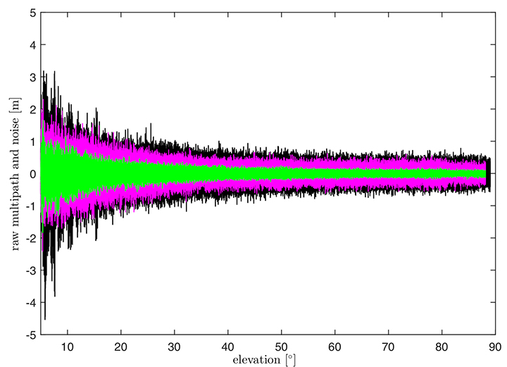
In Figure 2, the suppression of multipath and noise on the Galileo signals can be observed, where the code multipath and noise versus elevation for GPS L1 C/A BSPK(1), Galileo E1 (BOC (1,1)) and Galileo E5a (BPSK(10)) signals are shown. The code multipath and noise was estimated using the linear dual-frequency combination described in equation (2), where MPi represents the code multipath and noise on frequency i, ρi the code measurement, and ϕi,and ϕj represent the carrier-phase measurements on frequencies i and j, respectively. Carrier phase noises are small and can be neglected.
(2)
Figure 2. Raw multipath function of elevation for GPS L1, Galileo E1 (BOC (1,1)) and Galileo E5a (BPSK(10)) signals.
The multipath on the Galileo E1 (BOC(1,1)) signal (the magenta curve) is lower than the GPS L1 C/A (BPSK(1))(black curve), especially for low elevation, where the advantage of the E1 BOC(1,1) is more pronounced. The lower values can be explained by the wider transmission bandwidth on E1 and the structure of the BOC signal. Galileo E5a (green data in Figure 2) again shows a better performance than Galileo E1. This was expected due to the higher chip rate and higher signal power. A comparison of the raw multipath and noise standard deviations for GPS L1, L5 and Galileo E1, E5a signals is presented in Figure 3.
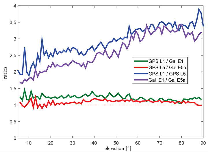
Figure 3. Ratios of the multipath and noise standard deviation function of elevation.
The curves there show the ratios of the standard deviations for each elevation bin. The values for GPS L1 are almost 1.5 times larger than those for Galileo E1 BOC(1,1) (green curve) for elevations below 20°. For high elevations, the ratio approaches 1.0. This corresponds to the observations in the raw multipath plot ( Figure 2). With the same signal modulation and the same chip rate, E5a and L5 have very similar results (red curve), and the ratio stays close to 1.0 for all elevations.
The blue and the purple curves in Figure 3 show the ratio of GPS L1 C/A (BPSK(1)) and GPS L5 (BPSK(10)), and Galileo E1 (BOC(1,1)) and Galileo E5a (BPSK(10)), respectively. The ratio of GPS L1 to GPS L5 (blue curve) increases with elevation from values around 2.5 for low elevations, reaching values above 3.5 for elevations higher than 60°. As Galileo E1 performs better, the ratio between Galileo E1 and Galileo E5a (purple curve) is smaller, from a value of 1.5 for elevations below 10 degrees to a value of 3.0 for high elevations.
Until now, we have presented the evaluation of raw code noise and multipath. However, in GBAS, carrier smoothing is performed to minimize the effect of code noise and multipath. The value that describes the noise introduced by the ground station is represented by a standard deviation called σpr_gnd and is computed based on the smoothed pseudoranges from the reference receivers. In the following section, we focus on the evaluation of σpr_gnd using different signals and different smoothing time constants. Note that, in this study, σpr_gnd contains only smoothed multipath and noise; no other contributions (for example, inflation due to signal deformation or geometry screening) are considered.
B-values and σpr_gnd
B-values represent estimates of the associated noise and multipath with the pseudorange corrections provided from each receiver for each satellite, as described in Eurocae ED-114A and RTCA DO-253C. They are used to detect faulty measurements in the ground system. For each satellite-receiver pair B(i,j), they are computed as:
(3)
where PRCTX represents the candidate transmitted pseudorange correction for satellite i (computed as an average over all M(i) receivers), and PRCSCA(i,k) represents the correction for satellite i from receiver k after smoothed clock adjustment, which is the process of removing the individual receiver clock bias from each reference receiver and all other common errors from the corrections. The summation computes the average correction over all M(k) receivers except receiver j. This allows detection and exclusion of receiver j if it is faulty. If all B-values are below their thresholds, the candidate pseudorange correction PRCTX is approved and transmitted. If not, a series of measurement exclusions and PRC and B-value recalculations takes place until all revised B-values are below threshold. Note that, under nominal conditions using only single-frequency measurements, the B-values are mainly affected by code multipath and noise.
Under the assumption that multipath errors are uncorrelated across reference receivers, nominal B-values can be used to assess the accuracy of the ground system. The standard deviation of the uncertainty associated with the contribution of the corrections (σpr_gnd) for each receiver m is related to the standard deviation of the B-values by:
(4)
where M represents the number of the receivers and N represents the number of satellites used. The final sigma takes into account the contribution from all receivers and is computed as the root mean square of the standard deviation of the uncertainties associated with each receiver (Equation 4).
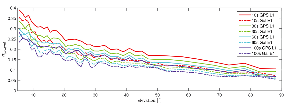
Figure 4 shows the evaluation of (σpr_gnd) for the Galileo E1, BOC(1,1) signal and the GPS L1 C/A signal for increasing smoothing time constants (10, 30, 60, and 100 seconds). Starting with a 10-second smoothing constant, Galileo E1 shows much better performance than GPS L1. The difference shrinks as the smoothing constant increases due to the effectiveness of smoothing in reducing noise and short-delay multipath. However, even with 100-second smoothing (the purple curves), Galileo E1 BOC(1,1) shows lower values of (σpr_gnd).
Figure 4. σ(pr_gnd) versus elevation for Galileo E1 (dotted lines) and GPS L1 (solid lines for different smoothing constants: red (10s), green (30s), cyan (60s), purple (100s).
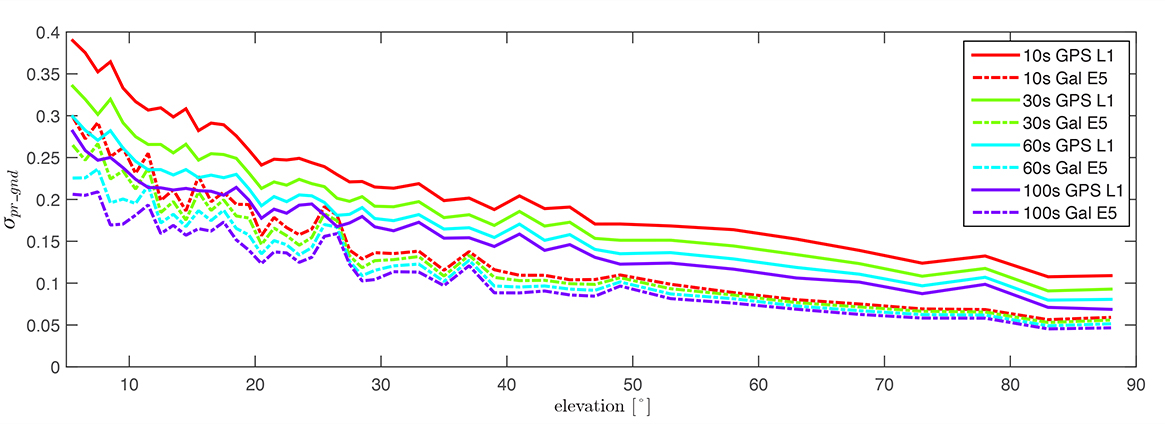
A similar comparison is presented in Figure 5, of the performance of GPS L1 and Galileo E5a. The Galileo E5a signal is significantly less affected by multipath, and the difference stays more pronounced than in the Galileo E1 – GPS L1, even with 100-second smoothing. It can be also observed that the Galileo signals have a lower sensitivity to the smoothing constant. The Galileo E1 signal shows an increase of sensitivity for low elevations (below 40°), while on E5a, a smoothing constant larger than 10 seconds has almost no impact on the residual error. Thus, a shorter smoothing constant on Galileo E5a generates approximately the same residual noise and multipath a 100-second smoothing constant on GPS L1.
Figure 5. σ(pr_gnd) versus elevation for Galileo E5a (dotted lines) and GPS L1 (solid lines) for different smoothing constants: red (10s), green (30s), cyan (60s), purple (100s).
The values for (σpr_gnd) are, however, impacted by the number of satellites which are used to determine a correction. Since only a very limited number of satellites broadcasting L5 and Galileo signals are currently available, these results should be considered preliminary. The first evaluations strongly indicate that with the new signals, we get better ranging performance. Based on the performance advantage of the new signals, a decrease of the smoothing constant is one option for future application. This would reduce the time required (for smoothing to converge) before including a new satellite or re-including a satellite after it was lost.
In the current GAST-D implementation, based on GPS L1 only, guidance is developed based on a 30-second smoothing time constant. A second solution, one with 100 seconds of smoothing, is used for deriving the Dv and Dl parameters from the DSIGMA monitor and thus for protection level bounding (it is also used for guidance in GAST-C). During the flight, different flight maneuvers or the blockage by the airframe can lead to the loss of the satellite signal.
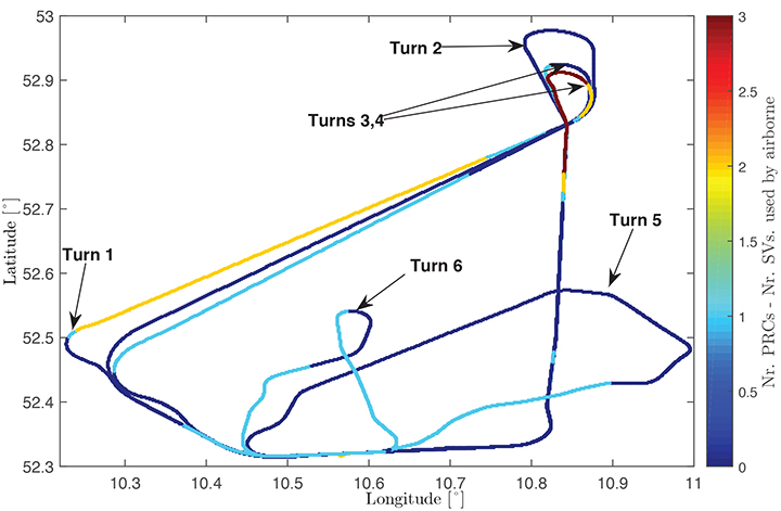
Figure 6 shows the ground track of a recent flight trial conducted by DLR in November 2014. The colors represent the difference between the number of satellites used by the ground subsystem (with available corrections) and the number of satellites used by the airborne subsystem in the GAST-D position solution. One of the purposes of the flight was to characterize the loss of satellite signals in turns. In turns with a steeper bank angle, up to 3 satellites are lost (Turns 1, 3, and 4), while on a wide turn with a small bank angle (Turn 2), no loss of satellite lock occurred. It is also possible for airframe to block satellite signals, leading to a different number of satellites between ground and airborne even without turns.
Figure 6. Ground track of a flight trial conducted by DLR. The colors represent difference between number of SVs used by the ground system and number of SVs used by the airborne.
With this in mind, a shorter smoothing constant would allow the satellites lost to turns or to airframe blockage to be re-included more rapidly in the position solution. However, a new smoothing constant would have to be validated with a larger amount of data. Data from flights trials has to be evaluated as well to confirm that similar levels of performance are reresentative of the air multipath and noise.
In a future dual-frequency GBAS implementation, an important advantage of lower multipath and noise is to improve the Ifree position solution. In earlier research, we demonstrated that the error level of the Dfree solution is almost the same as for single-frequency, but an increase in error by a factor of 2.33 was computed for the Ifree standard deviation based on L1 C/A code and L2 semi-codeless measurements.
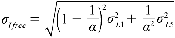
If the errors on L1 (E1) and L5 (E5a) code and carrier phase measurements are statistically independent the standard deviation of the σIfree can be written as,
(5)
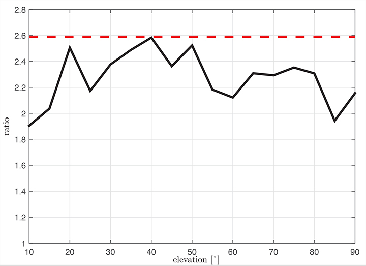
where α=1−f 21 ∕ f 25, and σL1,σL5 represent the standard deviations of the smoothed noise and multipath for L1 (E1) and L5 (E5a), respectively. Considering σpr_gnd,L1(E1)) = σpr_gnd,L5(E5a)) in equation (5), the noise and multipath error on Ifree (σIfree) increases by a factor of 2.59.
Figure 7 shows the ratio σIfree/σL1 using measured data. We observe that the measured ratio (the black curve) is below the theoretical ratio computed based on the assumption of statistically independent samples (the constant value of 2.59). This is explained by the fact that the multipath errors in the measurements are not independent but have some degree of statistical correlation. The standard deviations are computed based on the same data set used in the raw multipath and noise assessment using 100-second smoothed measurements sorted into elevation bins of 10° spacing.
Figure 7. Measured ratio σIfree/σL1 function of elevation.
Conclusion
We have shown how GBAS can benefit from the new signals provided by the latest generation of GPS and Galileo satellites. We have demonstrated improved performance in terms of lower noise and multipath in data collected in our GBAS test bed. When GBAS is extended to a multi-frequency and multi-constellation system, these improvements can be leveraged for improved availability and better robustness of GBAS against ionospheric and other disturbances.
Acknowledgment
Large portions of this work were conducted in the framework of the DLR internal project, GRETA.
Manufacturers
The ground facility consists of four JAVAD GNSS Delta receivers, all connected to Leica AR 25choke ring antennas.
Mihaela-Simona Circiu is is a research associate at the German Aerospace Center (DLR). Her research focuses on multi-frequency multi-constellation Ground Based Augmentation System. She obtained a 2nd level Specialized Master in Navigation and Related Applications from Politecnico di Torino.
MIchael Felux is is a research associate at the German Aerospace Center (DLR). He is coordinating research in the field of ground-based augmentation systems and pursuing a Ph.D. in Aerospace Engineering at the Technische Universität München.
Sam Pullen is a senior research engineer at Stanford University, where he is the director of the Local Area Augmentation System (LAAS) research effort. He has supported the FAA and others in developing GNSS system concepts, requirements, integrity algorithms, and performance models since obtaining his Ph.D. from Stanford in Aeronautics and Astronautics.
April marks the 20th anniversary of GPS FOC. U.S. Air Force Space Command declared Full Operational Capability (FOC) for the GPS constellation April 27, 1995, signifying the system met all requirements with 24 operational Block II/IIA satellites in their assigned orbital slots and providing both the military Precise Positioning Service (PPS) performance standard and the civil Standard Positioning Service (SPS) performance standard.
FOC was formally announced on July 17, 1995.
GPS IIF-9 Launch on March 25
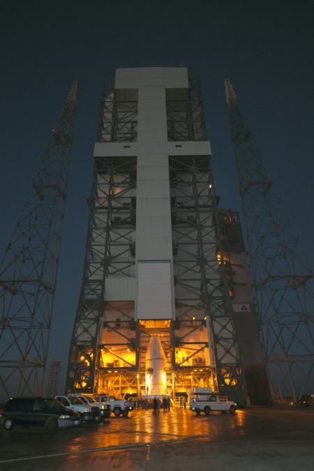
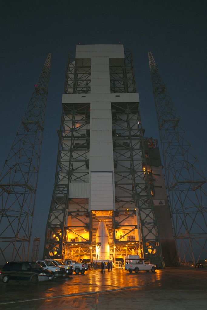
As this magazine went to press on March 19, the U.S. Air Force’s ninth GPS Block IIF satellite (GPS IIF-9) was being readied for a March 25 launch [since successfully launched]. The satellite was encapsulated in the Delta IV rocket’s 4-meter-diameter nose cone at a processing facility, and moved to the launch pad at Space Launch Complex 37 for mating to its booster inside the mobile service tower.
Launch is scheduled for March 25 at 2:36 p.m. U.S. Eastern time from Space Launch Complex 37 at Cape Canaveral Air Force Station, Fla. GPS IIF-9 marks the 29th Delta IV launch and the 57th operational GPS satellite to launch on a ULA or heritage launch vehicle.
CNAV Performance Compares Favorably to Legacy Signals
A March 5 announcement concerning the new L2C and L5 GPS civil signals states: “CNAV Message Types 10, 11, 30 and 33 are currently transmitted on seven GPS IIR-M (L2C) and eight GPS IIF satellites (L2C and L5). A Modernized Navigation (MODNAV) Tool integrated with the GPS ground control software (Architecture Evolution Plan or AEP) is generating the CNAV data messages. Daily CNAV uploads began December 31, 2014, and the U.S. Air Force reports that signal performance of CNAV matches or slightly outperforms Legacy performance: average user range error (RMS URE) from 25 February – 3 March 2015 was 0.50 m for Legacy and 0.57 m for Modernized; best week for Modernized signals since the broadcast initiated April 2014 was 0.42 m for 6 – 13 January 2015.
“Users are reminded that these CNAV signals are ‘pre-operational’ and should be used with discretion until they become fully operational; the L5 message is currently set unhealthy,” concluded Rick Hamilton, CGSIC Executive Secretariat, USCG Navigation Center, in a status email to the Civil Global Positioning System Service Interface Committee (CGSIC).
Galileo Six, Seven, Eight: Lay Them Straight
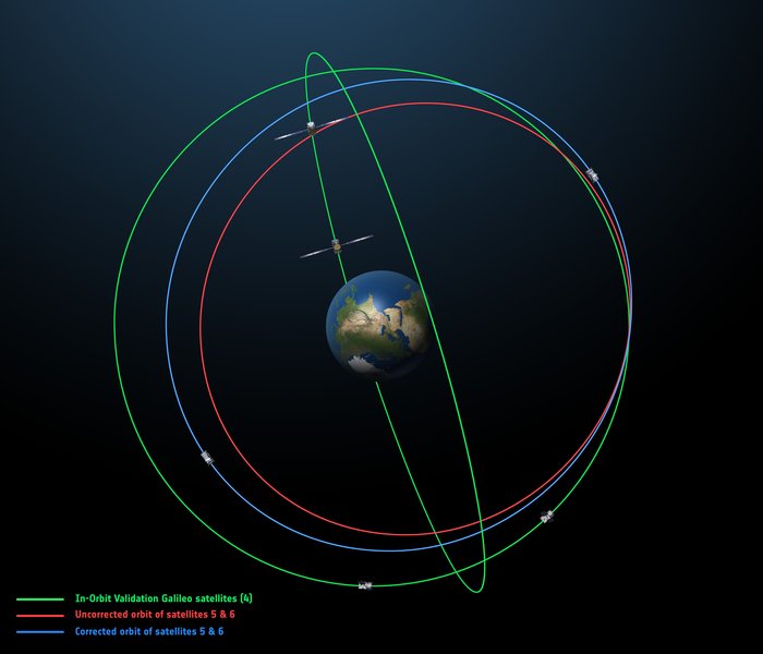
The original (in red) and corrected (in blue) orbits of the fifth and sixth Galileo satellites, along with that of the first four satellites (green).
On March 17, some stations participating in the International GNSS Service Multi-GNSS Experiment acquired E1 and E5a signals from Galileo 6 (FOC-FM2, GSAT0202). The satellite is using pseudorandom noise code E14.
This development follows the successful repositioning of the sixth Galileo satellite into a corrected orbit, which will now allow detailed testing to assess the performance of its navigation payload. A 20-meter-diameter antenna at the European Space Agency’s (ESA’s) Redu center in Belgium will study the strength and shape of the navigation signals at high resolution.
Launched with the fifth Galileo last August, its initial elongated orbit saw it traveling as high as 25,900 kilometers above Earth and down to a low point of 13,713 kilometers — confusing the Earth sensor used to point its navigation antennas at the ground.
A recovery plan was devised between ESA’s Galileo team, flight dynamics specialists at ESA’s ESOC operations centre and France’s CNES space agency, as well as satellite operator SpaceOpal and manufacturer OHB. This involved gradually raising the lowest point of the satellites’ orbits more than 3,500 km while also making them more circular.
The fifth Galileo entered its corrected orbit at the end of November 2014. Both its navigation and search-and-rescue payloads were switched on the following month to begin testing. Now the sixth satellite has reached the same orbit.
This latest salvage operation began in mid-January and concluded six weeks later, with 14 maneuvers performed in total. Its corrected position is effectively a mirror image of the fifth satellite’s, placing the pair on opposite sides of the planet. The exposure of the two to the harmful Van Allen Belt radiation has been greatly reduced, helping to ensure future reliability.
The corrected orbit means they will overfly the same location on the ground every 20 days. This compares with a standard Galileo repeat pattern of every 10 days, helping to synchronize their ground tracks with the rest of the constellation.
“I am very proud of what our teams at ESA and industry have achieved,” said Marco Falcone, head of the Galileo system office. “Our intention was to recover this mission from the very early days after the wrong orbit injection. This is what we are made for at ESA.”
The decision whether to use the two satellites for navigation and search-and-rescue purposes will be ultimately made by the European Commission, as the system owner, based on the in-orbit test results and the system’s ability to provide navigation data from the improved orbits.
March 27 Launch Date for Galileo Seven, Eight
The seventh and eighth Galileo satellites, set for launch together on March 27, were placed onto the Fregat upper stage of their Soyuz ST-B launcher in mid-March. [The satellites have been successfully launched.]
The Fregat stage will hold the satellites in place during their four-hour flight into orbit 22,300 kilometers above the Earth. Then, at the correct altitude, the two satellites are sprung away in opposing directions.
The Fregat upper stage was blamed for theAugust mis-delivery of Galileo satellites five and six. The root cause of the anomaly producing the wrong orbits was a shortcoming in the system thermal analysis performed during stage design, according to findings by an independent inquiry board.
The anomaly occurred during the flight of the launcher’s fourth stage, Fregat. It occurred about 35 minutes after liftoff, and was due to a temporary interruption of the joint hydrazine propellant supply to the Fregat thrusters. The interruption in the flow was caused by freezing of the hydrazine, resulting from the proximity of hydrazine and cold helium feed lines, these lines being connected by the same support structure, which acted as a thermal bridge. Ambiguities in the design documents allowed the installation of this type of thermal bridge between the two lines.
IRNSS Launch Scheduled for March 29
The launch of the fourth satellite for the Indian Regional Navigation Satellite System, previously scheduled for March 9, was postponed until March 29 at 13:00 UTC, due to the replacement of a faulty telemetry transmitter on the satellite. [The satellite has been successfully launched.]
IRNSS-1D will be fourth in the seven-spacecraft IRNSS constellation.
BeiDou, Too, in Late March
There are indications that the first satellite in the BeiDou Phase 3 expansion may be launched by the end of March [since successfully launched]. Apparently, a BeiDou satellite has been shipped to the Xichang launch site, and tracking ships have left port for the open ocean. Also, a philatelic first day cover for the launch (a common Chinese practice) has been issued with a March 2015 inscription. This is likely a launch of a medium Earth orbit (MEO)satellite.
Where It All Began for Galileo and EGNOS
The European Space Agency issued a press information notice on June 11, 1995 — in the same timeframe as the GPS FOC announcement noted on the previous page — titled “Europe’s Contribution to a Navigation Satellite System.”
“The European Commission, the European Space Agency (ESA), and the civil aviation organisation EUROCONTROL have agreed to cooperate on a joint programme).The European Satellite Navigation (ESN) Action Programme, elements of which are GNSS-1 [First Generation Global Navigation Satellite System] and GNSS-2, is planned to run for five years (from mid-1995 to mid-2000) with a budget of the order of 150 million euros.
“National aviation authorities and the parties involved in the action programme see Europe’s commitment to satellite navigation as being of strategic significance for the future.
“The main objective of the programme is to develop technologies that will ensure that data from the two existing Global Navigation Satellite Systems — the United States’ GPS and Russia’s GLONASS — which are both under military control, will also be available for civil use on a reliable basis and will provide the requisite precision.In parallel, studies will be conducted in order to make preparations for a second generation satellite-navigation and positioning system (GNSS-2), to be deployed as from 2005.
“In the first phase (GNSS-1), ESA’s contribution to the joint action programme will be EGNOS [European Geostationary Navigation Overlay Service].Satellites stationed in geostationary orbit at an altitude of about 36,000 km will relay to aircraft, shipping or road vehicles information that will enable the recipients to determine their actual positions with greater precision than is possible by using GPS/GLONASS data alone.Civil users of those systems receive artificially degraded data deviating by about 100 metres.EGNOS, will enable in particular, to increase the number of satellites that can be seen by a given user within the geostationary broadcast area.
“Around the period 2005–2008, after completing a trial period, the new system is due to be used as sole means.”
Galileo, Previously GNSS-2
“It is planned to develop GNSS-2 in the period between 2005 and 2020, building on experience acquired under GNSS-1.From the technical viewpoint, the second generation will be a considerable improvement on the first in terms of reliability, precision and availability.
“However, if Europe were to confine itself to developing the relevant technologies, its industry would have only a very slim chance of being involved in the construction of the satellites for the system or in the control and user segments for a second-generation civil system (GNSS-2). Given that U.S. and Russian firms are the current leaders in this area, it is necessary for strategic reasons for Europe to carry out a comprehensive development and demonstration programme as it must be able to prove it has the requisite capabilities before GNSS-2 becomes operational, which, in the experts’ opinion, will be from 2005.
“The time schedule foreseen for the different steps can be summarised as follows:
GNSS-1 mission analysis and definition studies: mid-1995 to mid-1996
European GNSS-1 pre-operational mission (task 1): to end 1997. Development of the geostationary network, following the Inmarsat III launch and first ranging demonstration phase
GNSS-1 (task 2): 1996 to end 1998. In parallel to the development of the network, the Ground Integrity Channel will be set up, followed by a second demonstration phase
GNSS-1 (task 3): 1997 to early 2000. Wide Area Differential service for precision approaches to be set up and tested
Introduction of GNSS-1 as sole means: 2000/2003.”
GPS World is indebted to Richard Langley’s CANSPACE archive of historical documents for this note of interest.
Winners in the 30 categories will be announced in October.
The 2015 European Satellite Navigation Competition (ESNC), an international innovation competition that recognizes the best ideas in satellite navigation, will run from April 1 to June 30. Winners will be announced in October.
There are more than 20 regions participating, and the ESNC will award prizes worth a total of €1 million in 30 categories.
“Satellite navigation is an essential element of modern mobility and a key technology in particular, in the age of a data-driven economy. This is exactly where the European Satellite Navigation Competition comes in. It provides a public platform to the creative community in order to help promising ideas turn into solutions that are commercially mature and generate added value for society,” said Alexander Dobrindt, Germany’s Federal Minister of Transport and Digital Infrastructure (BMVI).
A jury of international research and industry experts will select the year’s overall champion among the winners of the categories, which comes with an additional €20,000 and access to a six-month incubation program in the champion’s preferred region.
International kick-off for the 2015 ESNC is scheduled for April 21 in London.
“As the Galileo satellite constellation continues to expand, efforts to promote corresponding applications will become increasingly important. This is where the ESNC is already playing a key role,” said Matthias Petschke, the European Commission’s director of satellite navigation programs. “As such, the Commission is definitely looking forward to seeing the creative and innovative GNSS-based applications submitted this year.”
This year’s special topic prizes are being sponsored by the European GNSS Agency (GSA), the European Space Agency (ESA), the German Aerospace Center (DLR) and the Ministry of Transport and Digital Infrastructure (BMVI) in cooperation with the German Federal Ministry for Economic Affairs and Energy (BMWi). Entrants may submit prototypes to the GNSS Living Lab Challenge, while the University Challenge specifically addresses students and research assistants.
“Those who enter the ESNC benefit in particular from our global network, which provides them with tailored support in developing their business concepts and bringing them to market,” said Thorsten Rudolph, managing director of Anwendungszentrum GmbH Oberpfaffenhofen.
All of the information on this year’s prizes, partners, and terms of participation is available at the ESNC website.
McMurdo Group, maker of end-to-end search and rescue solutions, has received formal certification from the U.S. Federal Aviation Administration (FAA) and European Aviation Safety Agency (EASA) for its Kannad Integra ARINC 429 Navigation Interface.
Based on the ARINC 429 GPS communications standard for most commercial aircraft, the interface, when used with the Kannad Integra Emergency Locator Transmitter (ELT), provides dual GPS redundancy that can result in aircraft being found much faster compared to standard ELTs in event of an emergency. The solution has already been selected by aircraft manufacturers including Pilatus, Embraer and Airbus Helicopters.
Traditional ELTs rely on an aircraft’s external antenna and GPS equipment, which is subject to failure in the event of an emergency. The Kannad Integra ELT, however, can operate independently of the aircraft to provide key positioning data through its built-in internal antenna and embedded GPS receiver. The Integra ARINC 429 navigation interface stores the latest known position of the aircraft based on the aircraft navigation system data. This data is then used by the built-in Integra GPS for better location accuracy and a higher chance of rescue.
The Kannad Integra ELT and Integra ARINC 429 Navigation Interface are suitable for commercial aircraft, helicopters, business jets and airlines. Once activated, the Integra ELT transmits a distress signal to alert international rescue services to the emergency location via the global Cospas-Sarsat Search and Rescue satellite system, which has helped to save more than 37,000 lives since 1982.
“McMurdo’s Kannad products have been chosen by the world’s leading aircraft manufacturers and airlines for their quality, reliability and innovation,” said Christian Belleux, head of McMurdo’s Kannad Aviation Business Unit. “This new ARINC 429 interface is yet another example of how we are helping to shape the present and the future of aviation safety.”
When subjected to very strong interference, a GNSS receiver can be totally blinded and stop working. This is often the scope of intentional jammers. However, in a number of cases the presence of interference is severe enough to significantly decrease receiver performance, but not so much as to make the receiver lose its lock on the satellite signals or blind the acquisition of the satellite signals.
Such intermediate power values turn out to be the most dangerous cases, because sometimes they cannot be detected, but lead to a worsening of the positioning performance. The accuracy of the position solution depends on, among others, the quality of the pseudorange measurements and/or the phase measurements. Thus, when radio-frequency interference (RFI) degrades the pseudorange and phase measurements or induces cycle slips on the phase measurements, the accuracy of the position solution will decrease.
Impact on the Front End
The front-end filters the incoming signal, demodulating it to the chosen intermediate frequency before performing the analog-to-digital conversion (ADC).We must consider the presence in the front end of the adjustable gain control (AGC) between the analog portion of the front end and the ADC. When the GNSS band is interference-free, AGC gain depends almost exclusively on thermal noise, since the received signal power is below that of the thermal noise floor. When in-band interference is present, the AGC will squeeze the incoming signal to match the maximum dynamics of the ADC, causing a reduction of the amplitude of the useful signal, which may be lost. This may typically happen in the presence of some kind of wide-band interference (WBI) spread over a bandwidth larger than the passband of the front-end filter.
With narrow-band (NBI) or continuous-wave interference (CWI), statistics of the digital signal at the ADC output are also affected. In this case the AGC can still compress the input signal to avoid a stronger saturation, but the following receiver stages will have to deal with a GNSS contribution quantized only on lower levels.
In the presence of stronger interference, even the other components of the front end (filters and amplifiers) may be led to work outside of their nominal regions, generating nonlinear effects or clipping phenomena (in which the signal amplitude exceeds the hardware’s capability to treat them). In both cases, spurious harmonics are generated and mixed with the useful signal in the front end itself.
Impact on the Acquisition Stage
If the interference is not driving the AGC/ADC to full saturation, the acquisition module is still able to perform its task, processing the interfered signal to estimate the code phase and the Doppler shift with respect to the local code. The correlation with the local code can be seen as a spreading operation followed by a filter.
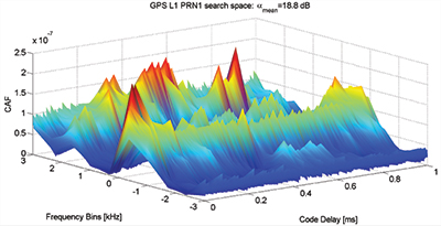
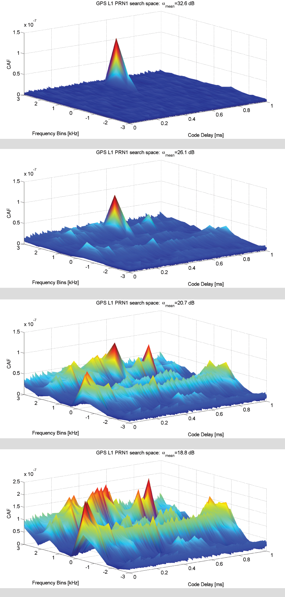
Figure 1. GPS L1 C/A acquisition search space in (a) an interference-free environment and in the presence of (b) –140 dBW in-band CWI; (c) –135 DBW in-band CWI; (d) –130 dBW in-band DWI.
Figure 1 showsthe acquisition search space for different levels of theinterfering power of a CWI from –140 to –130 dBW compared to the interference-free case. The search spaces depicted for the four scenarios are achieved using 1 ms of coherent integration time and three non-coherent accumulations, and the peak-to-noise-floor separation defined as
is considered as a figure of merit. The value of αmean decreases as the interfering power increases, thus increasing the probability of a false alarm. With the increasing power of the CWI, a modulation effect in the search space floor in the Doppler domain dimension can be observed. Such an effect is mainly determined by the new harmonics components generated by the multiplication between the locally generated carrier and received CWI. Such an effect also depends on how the interfering signal and the useful GNSS signal are combined at the entrance to the acquisition block, which in turn depends on the random variables φ0 and θint.
In the presence of WBI, a different effect is observed in the acquisition search space. Considering a band-limited Gaussian white noise spread all over the GNSS useful filtered signal components, the effect on the CAF envelop is an increase in the noise floor. This increases the search space noise floor. The presence of additive band-limited noise causes a uniform increase in the noise floor tin the search space that might mask the correct correlation peak and thus fool the acquisition process.
Impact on the Tracking Stage
Interference impact on the tracking stage has a direct consequence on the quality of the measured pseudorange. Harmful interfering signals increase the variance of the time-of-arrival (TOA) estimate by the discriminator and modify the shape of the S-curve of the code discriminator, thus creating in some cases a bias in the measurements.
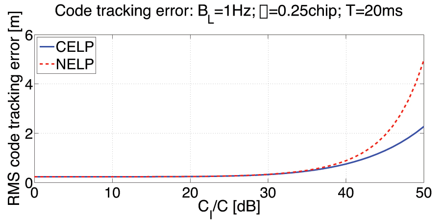
Figure 2 depicts outputs of the early-prompt-late correlators. In the presence of in-band CWI and of NBI, the interference is injected 9.3 seconds after the beginning of the tracking stage where the receiver is correctly locked on the received signal. A CWI, shifted 200 kHz with respect to the signal intermediate frequency (in correspondence with a C/A code spectrum line), increases the noise at the correlators outputs and leads to harmonic behavior of the early-prompt-late correlator outputs.
Figure 2. GPS L1 C/A code tracing error comparison: coherent and non-coherent early-late processing (CELP and NELP).
NBI increases the variance of the correlators’ outputs; this directly increases the pseudorange error and the noise on the receiver phase measurements. Additive band-limited noise leads to an overall increase in the carrier phase discriminator output variance over the 3σ threshold, which for a PLL two-quadrant arctangent discriminator is 45 degrees. When in presence of strong CWI, a sudden jump of the phase discriminator output is detected as soon as the CWI is injected onto the received signal.
Impact on the Estimated Signal-to-Noise Ratio
Sticking to the definition of C/N0 as the ratio between the received power and the power spectral density due to thermal noise at the input of the receiver, the presence of interference should not change the value, since the thermal noise is not increasing. However, the C/N0 value provided by the receivers is estimated on the basis of the correlator outputs at the tracking stage. For this reason the estimation is affected by the presence of the additional (nonthermal) noise generated by the interference. The variation of the C/N0 can also be used as observable for interference (or other threats) detection.
Chapters: The Interference Threat; Classification of Interfering Sources and Analysis of the Effects on GNSS Receivers; The Spoofing Menace; Analytical Assessment of Interference on GNSS Signals; Interference Detection Strategies; Classical Digital Signal Processing Countermeasures to Interference in GNSS; Interference Mitigation Based on Transformed Domain Techniques; Antispoofing Techniques for GNSS. The book is intended for members of the engineering/scientific community with pre-existing knowledge of satellite navigation principles and GNSS.
FabIo Dovis holds a Ph.D. in elecronics and communications engineering from Politecnico di Torino, Italy, where he is an associate professor.
The GPS World Galileo Product Showcase, from the April 2015 issue, features the latest products from seven top companies.
GPS/GLONASS/Galileo Receiver
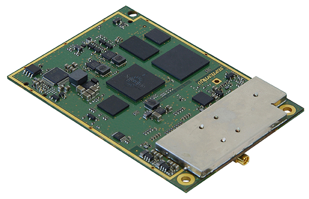
Septentrio AsteRx3 Photo: Septentrio
The AsteRx3 is a multi-frequency GPS/GLONASS/Galileo receiver is designed for demanding industrial applications. AsteRx3 features simultaneous high-quality GPS, GLONASS and Galileo tracking and a range of innovative features, such as the patented Galileo AltBOC tracking, the advanced multipath mitigation algorithm APME, LOCK+ tracking for exceptional tracking stability under high vibration conditions, RTK+ for extended RTK baselines and faster initialization, and AIM+, Septentrio’s Advanced Interference Mitigation technology, offering centimeter-level measurement quality for high-precision positioning, even in challenging environments.
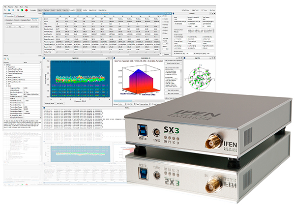
The IFEN SX3 multi-GNSS software receiver Photo: IFEN
IFEN’s SX3 multi-GNSS software receiver tracks all known GNSS signals in view, including Galileo signals, in real time on a standard laptop now and in the foreseeable future (up to 1,000 channels in parallel on a core i7). The included RF front end offers four RF frequency paths with 50-MHz bandwidth each, covering the entire GNSS L-band spectrum. The USB 3.0 interface enables high-speed data transfer with up to 8-bit quantization. An optional dual RF input front end can be used for attitude determination, reflectometry and other applications requiring the synchronized input from two antennas. An optional built-in shock and vibration robust OCXO reference oscillator (MIL-STD 202G) is available, which replaces the standard high-quality TCXO normally used.
The SX3 software lets users configure the data processing, including changing loop bandwidths, integration times and the main processing rate, and choosing between different correlation types. The software includes a multi-correlator providing a two-dimensional (code and Doppler) correlation function visualization in real-time. The receiver comes with several powerful processing algorithms like vector tracking, to improve the tracking of weak signals in degraded environments.
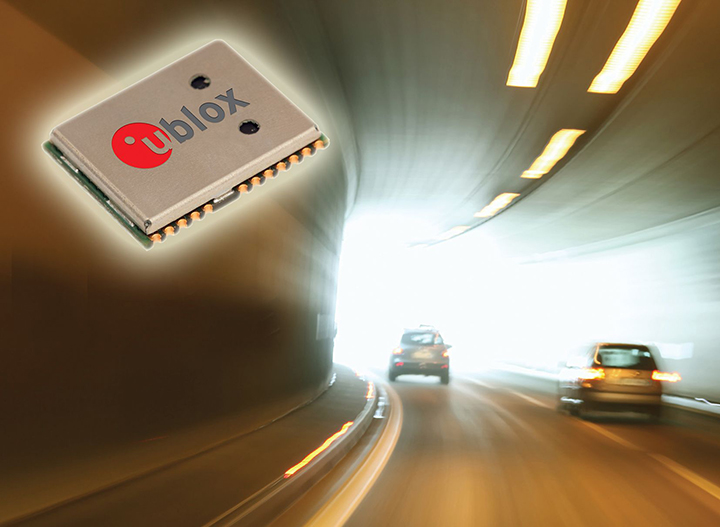
The NEO-M8L Automotive Dead Reckoning (ADR) module by u-blox has integrated motion, direction and elevation sensors. The module integrates gyro and accelerometer with u blox’ GNSS platform M8 to achieve high indoor/outdoor positioning performance for road vehicle and high-accuracy navigation applications.
The module is able to track all visible GNSS satellites including GPS, GLONASS, BeiDou, QZSS and all SBAS, with Galileo to be supported in a future firmware version. Concurrent reception of two GNSS systems is supported. The NEO-M8L module can output a position up to 20 times per second.
In addition to accessing the integrated module’s gyro and accelerometer data, accident reconstruction systems can provide the location of an accident to facilitate insurance claims even if a collision occurs in a tunnel or park house. High-end navigation devices are able to guide drivers through tunnels of several kilometers because of the accuracy of u-blox’ ADR system. Stolen vehicles can be located instantly due to continuous monitoring of sensor data and storage of location in non-volatile memory.
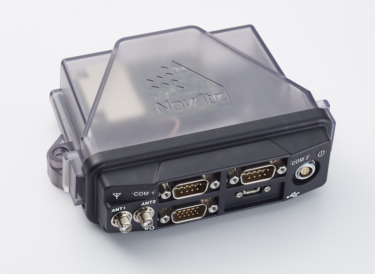
The NovAtel FlexPak6D enclosed GNSS receiver is a flexible dual-antenna solution for application developers seeking a high-precision heading-capable positioning engine for space-constrained applications.
Designed for efficient and rapid integration, the compact receiver tracks Galileo as well as GPS, GLONASS and BeiDou. Antenna placement is flexible: the antenna baseline can be set according to space available on a vehicle and heading accuracy required. The modular OEM6 firmware enables users to configure the receiver for unique application needs. Scalable for sub-meter to centimeter-level positioning, the FlexPak6D delivers NovAtel’s ALIGN precision heading and relative heading firmware, as well as its GLIDE firmware for smooth decimeter-level pass-to-pass accuracy and RAIM for increased GNSS pseudorange integrity.
The GNSS simulator in the vector signal generator R&S SMBV100A Photo: R&S
The GNSS simulator in the vector signal generator R&S SMBV100A is designed for development, verification and production of GNSS chipsets, modules and receivers. The simulator supports all possible scenarios, from simple setups with individual, static satellites up to flexible scenarios generated in real time with up to 24 dynamic Galileo, GPS, GLONASS, BeiDou and QZSS satellites. The simulator also supports Assisted GNSS (A-GNSS) test scenarios, including generation of assistance data for Galileo.
The simulator offers real-time simulation of realistic constellations with up to 24 satellites and unlimited simulation time. Flexible scenario generation includes moving scenarios, dynamic power control and atmospheric modeling. Users can configure realistic user environments, including obscuration and multipath, antenna characteristics and vehicle attitude.
The all-in-one TRIUMPH-LS by JAVAD GNSS combines a high-performance 864-channel GNSS receiver, all-frequency GNSS antenna, and a modern featured handheld. The 864 all-in-view channels include Galileo E1/E5A/E5B, GPS L1/L2/L5, GLONASS L1/L2/L3, QZSS L1/L2/L5, BeiDou B1/B2 and SBAS L1/L5.
The TRIUMPH-LS offers GUIDE data collection, Visual Stake-out (VSO), navigation, six parallel RTK engines, more than 3,000 coordinate conversions, advanced CoGo features, and rich attribute tagging on a high-resolution, bright, 800 x 460 bright display. Two 3-megapixel cameras enable recording of images along with GNSS data.
With VSO, the virtual location of a point to be staked can be seen by a “flag” shown on the Triumph-VS camera image. This visual aid helps users navigate quickly to a point and makes stakeout jobs fast and easy. VSO can be used as a convenient way to get close to a target point before switching to the regular stakeout mode to perform precise measurements.
More than 100 channels are dedicated to continuous interference monitoring. The Triumph-LS monitors and reports interference graphically and numerically with patent-pending interference protection. Interference awareness allows safe GNSS operation in a city, airport and military environment.
The unit can serve as base or rover. It has a GSM modem, UHF transmit and receive, and an internal high-performance geodetic antenna.
The TRIUMPH-LS automatically updates all firmware when connected to a Wi-Fi Internet connection.
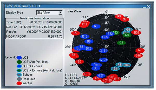
TeleOrbit’s software-defined radio receiver and GNSS interference monitoring tool receives and processes all available Galileo signals. Signals that are not yet transmitted and interference sources can be simulated and processed within the software tool.
Within a software-defined radio framework, the analog-to-digital converter is moved as close as possible to the antenna to perform most of the signal processing in software. This leads to adaptable solutions with lower hardware costs that can be easily extended to new signals and systems with only a software update.
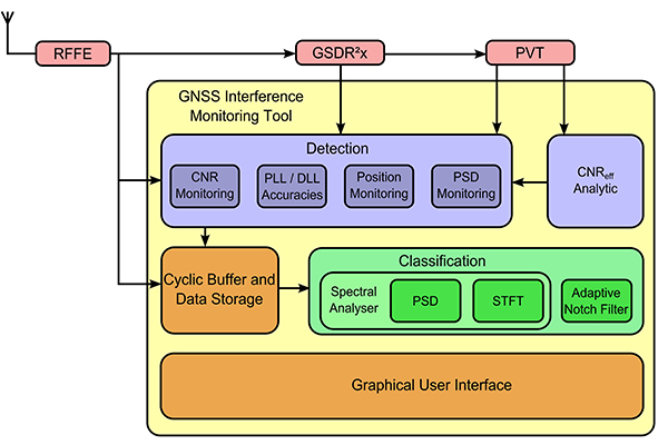
The GNSS Software Defined Radio Receiver (GSDR2X) developed by TeleOrbit’s sister company TeleConsult Austria can track most readily available signals from Galileo, GPS and SBAS. By utilizing input from TeleOrbit’s GNSS multi-system performance simulation environment (GIPSIE), even signals not yet transmitted by satellites can be tracked and processed by the GSDR2X. Furthermore, input data can be read from various radio frequency front-ends, either directly or from file.
The modular GSDR2X framework enables new capabilities, such as the GNSS Interference Monitoring Tool (GIMT), which enables the GSDR2X to detect and classify interfering and jamming signals (see figure).
Avanti Communications has been appointed by the UK Space Agency to deliver a crucial air navigation project in Africa, SBAS-AFRICA. The satellite operator has been awarded the contract under the agency’s International Partnership Space Programme (IPSP), which exists to open up opportunities for the UK space sector to share expertise in real-world satellite technology and services overseas.
Africa has just 3 percent of global air traffic, and yet air accidents in Africa account for roughly 20 percent of the worldwide total. By demonstrating potential improvements in flight safety via SBAS technologies, the project can provide socio-economic benefits to the continent, according to a news release from Avanti.
Based on prior cost-benefit modeling which identified a €1.7 billion potential economic benefit to the African aviation sector from the deployment of SBAS services, SBAS-AFRICA will help accelerate the adoption of GNSS-based flight operations, positively influence the evolution of aviation safety in Africa and encourage development in the wider African economy.
SBAS-AFRICA will deliver a satellite-based augmentation system for GNSS-based operations in the aviation sector, serving significant parts of Africa in partnership with a number of local stakeholders. The project will use a unique asset, Avanti’s ARTEMIS L1 Navigation transponder, to provide a navigation data broadcast service.
“SBAS-AFRICA brings an innovative and pragmatic approach to deploying SBAS services in Africa,” said Matthew O’Connor, Chief Operating Officer at Avanti Communications. “It establishes crucial collaboration between the UK and a number of African countries, including South Africa and Ghana. Participating countries will benefit hugely from expertise gained, placing them at the forefront of navigation services across the continent and, crucially, helping to improve aviation safety for a major generator of economic benefit in Africa.”
He continued, “The Artemis satellite will play an integral role in this project. We expect that such a showcase for its performance, accuracy and quality will provide further evidence of what can be achieved with this technology and lead to significant commercial opportunities.”
“The UK Space Agency is delighted to play a role in fostering new international partnerships that not only enable innovative UK space companies like Avanti to provide more high-tech exports that can boost our space sector but also allow the UK to widely share the considerable social and economic benefits that space technology and infrastructure can provide,” said David Parker, chief executive of the UK Space Agency.