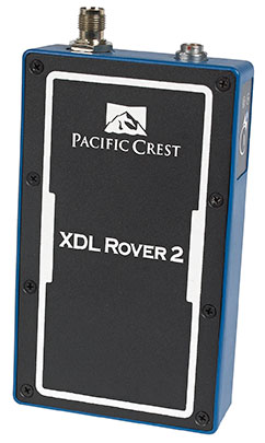
Trimble has introduced the Pacific Crest XDL Rover 2, an advanced, high-speed, wireless data link built to withstand the rigors of GNSS/RTK surveying and precise positioning.
The XDL Rover 2 is equipped with Bluetooth wireless communication for ease in configuration and operation. It can be quickly configured with an Android device in the field and UHF data can be transmitted via Bluetooth to a paired host device for operational efficiency.
The XDL Rover 2 is a lightweight, ruggedized UHF receiver designed for digital radio communications between 403 and 473 MHz in either 12.5 or 25 kHz channels. It is designed for high performance over the entire band. The XDL Rover 2 is pocket sized and provides for cableless operations. It features an internal, rechargeable battery for ease of use and portability that allows long operational hours.
“The XDL Rover 2 is an ideal, high-speed radio receiver for field operations that require a one-way communications link,” said Jess Cobb, business area director for Trimble’s Radio Communications Group. “Its interoperability with existing equipment and greater functionality allow customers to rapidly deploy the XDL Rover 2 for maximum productivity.”
This sophisticated radio leverages the latest generation XDL modem technology while remaining backward compatible with existing Pacific Crest and other products. By deploying the technology, users can instantly communicate with GNSS precise positioning receivers that share the same protocols throughout the world.
The XDL Rover 2 joins the line of XDL products that includes the XDL Micro, a transceiver OEM module. The XDL Micro is a 0.5-2.0 Watt UHF transceiver designed for integration into products that require either a one- or two-way radio communication link. The XDL radio line is based on the successful Pacific Crest ADL products.
Trimble has added advanced line acquisition technology to its Autopilot automated steering system Trimble OnSwath technology. The acquisition technology reduces the time lost turning at the end of a row by enabling the vehicle to make a tighter turn and approach the next line, or crop row, 50 percent faster.
Using OnSwath, the farmer can decrease idle driving time, fuel consumption, soil compaction, crop damage, and working time in the field — which can lead to cost savings. OnSwath is a free upgrade to customers using the Trimble Autopilot automated steering system.
The new OnSwath technology allows the user to customize their line acquisition to the vehicle, operation, and operator preference including adjusting turn angle, approach angle, and speed. Using OnSwath, the vehicle projects its path to the line, which allows it to get online faster. As a result of these improvements, vehicle performance is more controlled, predictable, and repeatable.
“By adding OnSwath to Trimble’s Autopilot steering system, we’ve enabled farmers to be more efficient with their field operations,” said Erik Ehn, Smart Machines business area director of Trimble’s Agriculture Division. “OnSwath saves time, money and fuel, while also decreasing soil compaction and crop damage. Since we’re providing the technology at no additional cost, farmers who use Trimble’s automated guidance can leverage OnSwath and measure how much it can save their farm.”
“With Trimble’s OnSwath, I’m able to get online much faster and more accurately,” said Joe Brightly, who began using the OnSwath technology this spring for planting and strip tilling operations. “After an end of row turn, I can get online in a matter of only a few feet, which has saved me a lot of time.”
OnSwath is available with a software update to the Trimble Autopilot system.
RT Logic has been awarded a $1 million follow-on contract to provide ground system components for the USAF GPS OCX program, bringing RT Logic’s total OCX contract awards to over $4 million. RT Logic is a subsidiary of Kratos Defense & Security Solutions, Inc.
OCX is the next generation GPS ground system designed to bring flexibility, adaptability, and modularity to the position, navigation, and timing (PNT) mission. RT Logic is the primary equipment supplier for the Command and Control (C2) portion of OCX, providing software front-end processor units and Air Force Satellite Control Network (AFSCN) gateways.
RT Logic supports Raytheon, the prime contractor for GPS OCX, with RT Logic’s net-centric software products for C2 of the GPS III satellites using next generation IP cryptosystems. The IP cryptosystems use industry-standard IP interfaces, eliminating the need for custom serial interfaces, which is intended to ease integration challenges, improve reliability, lower transition risk, and reduce cost.
RT Logic’s software-based products will enable Raytheon to add new features to meet evolving requirements as needed, the company said. In addition, RT Logic will build a high-fidelity lab environment that simulates the GPS mission string. This lab system will allow Raytheon to cost-effectively resolve issues, integrate and simulate new functionality, and maintain the system without impacting the operational mission or Raytheon’s regression testing schedules, the company said.
The troubled Galileo E20 satellite restarted E1 signal transmission Wednesday evening, August 6.
Galileo E20, also known as GSAT0104, the fourth in-orbit validation (IOV) satellite, has been set “unavailable until further notice” according to the European GNSS Service Centre because of a sudden, unexpected loss of power on May 27.
Based on a selected set of IGS MGEX stations and all CONGO stations, the first signals were tracked at AREG, AUT0, LLAG, and UNB3 at 23:13:00. No E5 signals and no navigation messages are currently transmitted. However, some JAVAD GNSS receivers report from time to time false E5a locks with zero or extremely small C/N0.
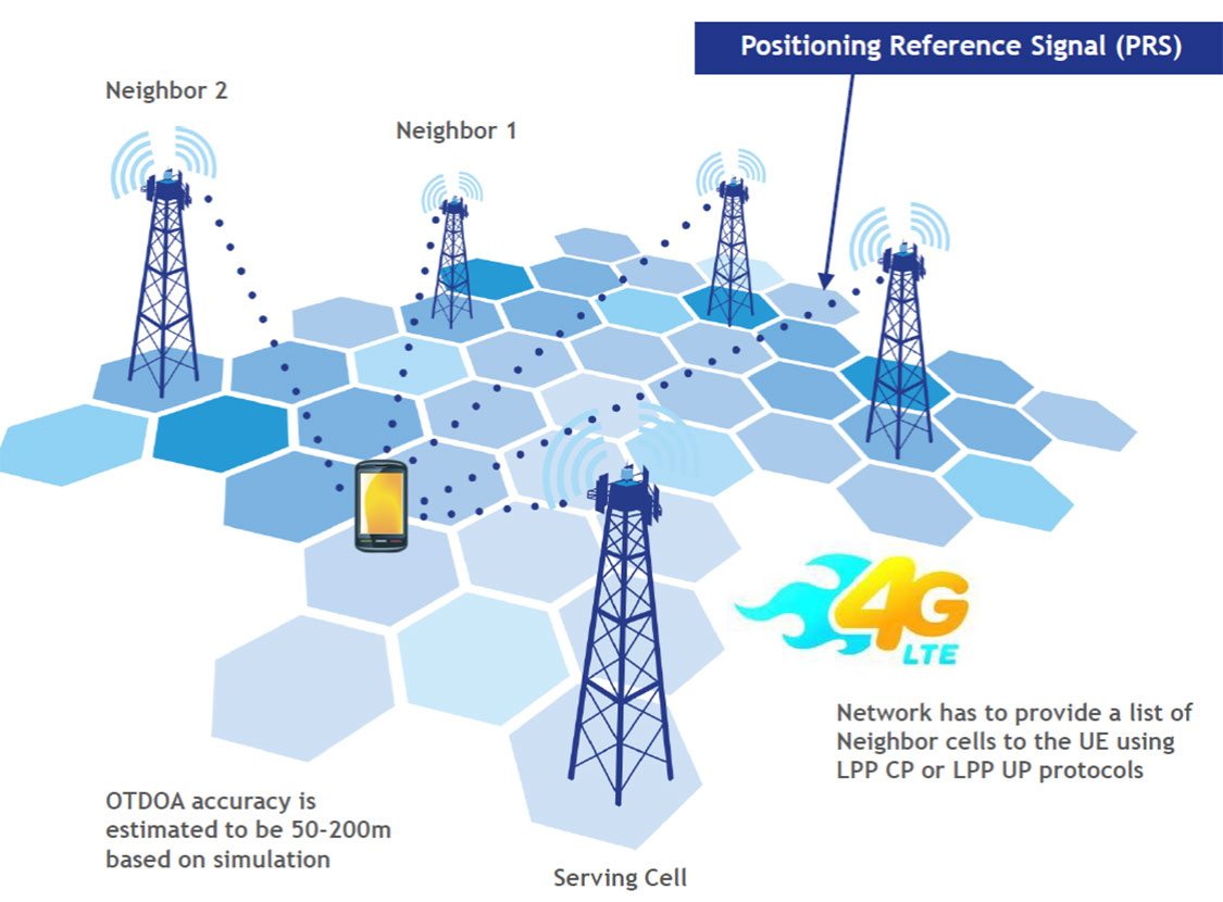
LTE brings a promise of improved location accuracy with new positioning technologies and their integration using hybrid techniques. Although established technologies such as A-GNSS (A-GPS and A-GLONASS) provides excellent performance in environments with a clear view of the sky, performance is often poor indoors, where detection of satellite signals is limited. In LTE, current standards support Observed Time Difference of Arrival (OTDOA), an advanced cellular positioning technology that can augment A-GNSS and provide a more accurate location fix for indoor scenarios.
With large-scale VoLTE rollouts imminent, leading operators are confronted with the need for extensive and complex testing of LTE positioning technologies to ensure VoLTE E911 works well from day one. Additionally, the FCC, whose current E911 regulations apply only to outdoor environments, has proposed stringent indoor requirements as a response to increased mobile usage for emergency calls and lack of accurate positioning information on calls that originate indoors.
“Roughly 70 percent of 911 calls are placed from wireless phones and a majority of these calls originate indoors, so there is a real urgency in providing better location accuracy for mobile users, wherever they are calling from,” said Nigel Wright, vice president at Spirent Communications. “Spirent is currently working with all the key industry players to evaluate OTDOA and its integration with other positioning technologies, and to enable operators to meet the location requirements for VoLTE E911 and the evolving FCC requirements.”
Spirent 8100 LTS has won widespread acceptance as the leading platform for location testing in the wireless industry, and with this latest capability is now able to support OTDOA Position Calculation Function (PCF). Minimum performance testing for OTDOA looks only at the raw measurements from the device, whereas use of OTDOA PCF enables full verification of a device’s position accuracy performance. Recognizing its importance, leading carriers have established their own OTDOA positioning performance requirements beyond bare minimum standards. Ensuring that devices fully meet these requirements as well as the evolving FCC regulations for E911 requires comprehensive testing.
“The Advisory Council is comprised of foundation members selected because of their unique expertise, background and reputations within the international navigation and timing community,” said Dana Goward, president of the foundation.
While the council will advise the foundation on an on-going basis, in-person meetings will be scheduled to coincide with those of the U.S. National PNT Advisory Board.
The RNT Foundation Advisory Council membership includes Donald Jewel, GPS World Defense Editor and United States representative; Chuck Schue, also from the U.S.; Refaat Rashad from Egypt; David Last from the United Kingdom; and Krzysztof Czaplewski from Poland.
Mitre’s new Time Anomaly Detection Appliqué (TADA) protects modern digital systems from spoofing attacks that can corrupt time source signals.
Successful spoofing attacks could result in navigational systems going haywire and grounding airplanes, jumbling of buying and selling orders, a shutdown of the stock market, or power-grid failures. Infrastructure and defense systems often rely on GPS’s unencrypted position, navigation, and timing (PNT) signal as their source of accurate time, accurate to about 14 nanoseconds.
The TADA system detects and, for certain users, mitigates timing attacks. “Almost every system has a need for precise and accurate time,” said Darrow Leibner, the Mitre TADA project lead. “Because GPS is accurate and ubiquitous, users have gotten away from implementing other time-keeping methods. That’s where the potential vulnerability comes in.”
TADA is designed to provide a cost-effective, reliable, and easy-to-use method for protecting GPS receivers against spoofing attacks. The system defends against spoofing by continuously comparing a trusted input, such as a known frequency or location, with those provided by the GPS receiver. When a difference between these two inputs is detected, TADA alerts the user to the suspected PNT anomaly.
For a trusted input, TADA uses an atomic clock frequency. For each second measured by the incoming GPS timing signal, TADA counts the number of frequency cycles generated by a Cesium clock. If the incoming GPS signal is valid, TADA will count exactly the expected number of Cesium frequency cycles. If TADA measures a higher or lower number of timing signals than expected, it will display the difference. A difference outside the acceptable margin of error will prompt TADA to alert its users that the GPS timing signal is possibly being spoofed.
In the same way it uses a trusted time source, TADA can also use a known location to detect a spoofing attack. To do this, the user inputs the location of a GPS receiver antenna into TADA. TADA monitors the reported position for any changes. Any reported change of the stationary location would most likely be due to spoofing attack and prompt an alert to the user. Once alerted by TADA to a spoofing attack, users can quickly switch to existing backup systems.
“This is not the invention of the lightbulb,” Leibner said. “Rather, it’s a clever use of existing technologies packaged in such a way that users obtain a greatly increased level of protection for a minimum of investment. None of the TADA components on their own are brilliant. But as one manufacturer said after seeing a detailed description of TADA, ‘It’s brilliantly simplistic.’”
The next stage in TADA’s development is to provide it with the capability to not only detect spoofing attacks, but to mitigate its effects and pinpoint their origin. Mitre will also continue to advocate that to bolster the nation’s infrastructure defenses against spoofing, TADA-like monitoring techniques be included within commercial product design.
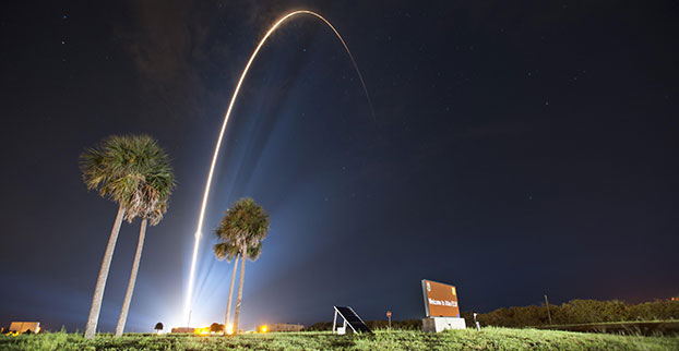
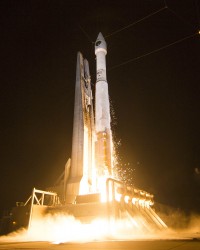
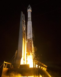
A United Launch Alliance (ULA) Atlas V rocket carrying the seventh GPS IIF satellite for the U.S. Air Force launched at 11:23 p.m. EDT Friday, August 1 (03:23 UTC, August 2), from Space Launch Complex-41 at Cape Canaveral, Florida.
GPS IIF-7 launches into orbit. (Photo credit: United Launch Alliance)
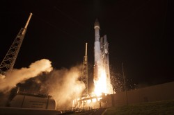
A United Launch Alliance (ULA) Atlas V rocket carrying the seventh GPS IIF satellite for the U.S. Air Force launched at 11:23 p.m. EDT Friday, August 1 (03:23 UTC, August 2), from Space Launch Complex-41 at Cape Canaveral, Florida.The Boeing-built satellite has sent the signals to controllers that confirm it is currently operating properly within the constellation.
Boeing and the Air Force will complete the full on-orbit checkout of the satellite in August. The GPS IIFs offer improved signal accuracy, better anti-jamming capability, longer design life and the new civilian L5 signal.
“We are providing our Air Force partner and GPS users with a steady supply of advanced GPS IIFs,” said Craig Cooning, president of Boeing Network & Space Systems. “Our robust launch tempo requires vigilance and attention to detail, and mission success is our top priority. We continue to partner with the Air Force and ULA to effectively execute the launch schedule.”
GPS IIF-7 is the seventh of 12 such satellites Boeing has built for the U.S. Air Force, and the third on-orbit delivery this year. GPS IIF-8, slated for launch during the fourth quarter, arrived at Cape Canaveral on July 16 to undergo final launch preparations. GPS IIF-7 will join a worldwide timing and navigation system utilizing 24 satellites in six different planes, with a minimum of four satellites per plane positioned in orbit approximately 11,000 miles above the Earth’s surface.
“Congratulations to the U.S. Air Force and all of our mission partners on the successful launch of the Atlas V carrying the GPS IIF-7 satellite,” said Jim Sponnick, ULA vice president, Atlas and Delta Programs. “ULA launch vehicles have delivered all of the current generation of GPS satellites, which are providing ever-improving capabilities for users around the world.”
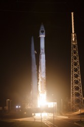
This mission was launched aboard an Atlas V Evolved Expendable Launch Vehicle (EELV) 401 configuration vehicle, which includes a 4-meter-diameter payload fairing. The Atlas booster for this mission was powered by the RD AMROSS RD-180 engine, and the Centaur upper stage was powered by a single Aerojet Rocketdyne RL10A engine.
The EELV program was established by the United States Air Force to provide assured access to space for Department of Defense and other government payloads. The commercially developed EELV program supports the full range of government mission requirements, while delivering on schedule and providing significant cost savings over the heritage launch systems.
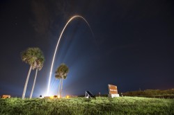
GPS IIF-7 launches into orbit. (Photo credit: United Launch Alliance)
According to Innovation editor Richard Langley, it appears that the satellite will be assigned PRN09, currently unused by the constellation.
The Initial NORAD 2-line element set indicates that the satellite has been launched into the F plane and is drifting towards its assigned orbital slot:
Includes: Tests Show Tech Can Meet FCC Indoor 911 Accuracy; InvenSense to Acquire Sensor Nav Companies Trusted Positioning, Movea; Business Aviation Agrees to Promote EGNOS Use at European Airports; Patent Issued for Dynamic Location Reporting; Remote Patient Monitoring to Reach €19.4B in 2018; News from the Esri User Conference; Google Acquires Satellite-Imaging Startup for $500M; EuroGeographics to Create Expert Group in GNSS Positioning; Geospatial Computing Book Published; USGS Releases Earthquake Hazard Map; Events
Scott McCormick, president of the Connected Vehicle Trade Association (CVTA) discusses Super Mobility Week, the Intelligent Transportation Systems’ World Congress, and what to expect in the connected vehicle market.
Topcon Tesla handheld controller combines the advantages of a PC tablet with the ruggedness of a fully equipped survey device.
An Oklahoma Survey Firm Is Increasing Productivity with Cloud-Based Solutions
By Larry Trojak
Until recently, the flow of real-time information and job-critical data between the office and personnel in the field for survey and construction has not kept pace with advances in onsite GNSS equipment. But enterprise software suites are closing the gap, producing across-the-board efficiencies, cost reductions, and an ability to bid more competitively.
Sisemore Weisz & Associates (SW&A) of Tulsa, Oklahoma, is an engineering specialist in site design and land planning, and has survey experience with ALTA/ACSM work, high-end civil construction, structural layout, and large survey control networks. Topcon’s cloud-based software suite Magnet gives SW&A the ability to have immediate access to the plans, data, and site information needed to respond to and complete the job.
“Providing the ability for any crew to immediately access their data from anywhere via a Tesla field tablet is invaluable. It’s literally changed the way we do business,” said SW&A chief of parties Shawn Collins.
Collins’ ultimate goal was to establish a platform for data collection, sharing, and transfer that best utilized today’s technology, including Internet access and the ability to email and text message crews in real-time.
His first instinct was that a tablet such as an iPad might be the answer, but iPads weren’t suitable for surveying Instead, they chose Topcon’s newly introduced Magnet Enterprise package along with a pair of Tesla controllers. Finding it the right solution, after a few weeks they bought more Teslas. “It was just the solution we needed,” Collins said.
Magnet Suite
Comprised of three individual software components — Field, Tools, and Office — as well as the Enterprise cloud environment itself, the Magnet suite of products is designed to bring real-time, cloud-based efficiency to any survey or construction operation, according to Jason Hallett, Topcon’s senior product manager for software applications.
“Magnet considers everything from data collection, to CAD, to data manipulation and reporting, to data exchange, to cloud-based project management in an enterprise environment,” Hallett said.
Components of Magnet:
Field. Connects field users to the cloud, and enables real-time communication, as well as cloud storage and data exchange. A powerful field software for topo, staking, roads, and calculations is included.
Tools. Allows the processing and exchange of data between the enterprise cloud and popular desktop applications, such as Autodesk Civil 3D.
Office. Exchanges design files, survey jobs, and surfaces through the enterprise cloud for simple project revisions and real-time survey data from the field.
Dillon Dossey is a one-man crew with Magnet and the cloud.
In the year since they began using Magnet, Collins said that the system has become an integral part of the way SW&A does business. “It can be something as simple as getting a crew working faster than we ever could in the past,” Collins said. “For example, say we are set to begin a large highway project several hours from the office, but we are wrestling with plans or have calculations that still need fine-tuning on one part of the job. In the past, the whole project would have been held up until those issues were resolved. Now, we can send a crew out with what we already have and, when that missing data is completed, upload it to the cloud for them to access when they need it. As a result, production is on track, deadlines are met, and the customer is pleased.”
Re-routing crews — a time-consuming effort in the past —is now a simple process. “If a crew wraps up a project and needs to be re-routed from their original follow-up job, they now can simply check email or chats on their Tesla and see what’s changed. All of their pertinent information is going to be in the chat and in the cloud — all the directives are there, all the paperwork, everything they need to make a fast, seamless transition to the next job without having to come back to the office. Just minimizing those trips back here has shown us a nice 14 percent reduction in fuel costs since going forward with Magnet. And taking that 14 percent off of a bid allows us to be that much more competitive.”
As chief of parties, one of Collins’ primary roles is quality control on projects, and Magnet has helped. “I can show up to a site to see how a crew is doing, have them upload data to the cloud, and confirm their progress. As a result, managing the parties, managing the control, managing the job flow is so much better. And, contrary to what one might think, the fact that the crews know they are being checked has not had any downside at all. They know we are all on the same team and appreciate that this technology is helping make us more competitive — which ultimately benefits everyone.”
Collins has witnessed dramatic changes in his 30 years of surveying, but sees Magnet as a game-changer for data management and flow, the exchange of information, and bidding on jobs which, thanks to Magnet Enterprise’s cloud-based environment, has become a streamlined, efficient process.
“It is now possible to easily cross-reference jobs to help in the bidding process,” he said. “We can go into our cloud and see if we did a similar job before, and, if so, view the work order, view the billing files, see how much that job actually cost, see what we bid on it, see if we were profitable, see how we did for time management, and so on. In the past that would have been a painstaking, time-consuming process. But with that all data readily at hand, it is easy to put together an informed, competitive bid and get it out to the client in no time.”
One area that Collins hopes to pursue further is deeper client involvement. “We recently added 5 GB of capacity to our cloud storage, and that should help us move forward with that push. Making it possible for the client to look at the project as it exists in real-time, to be able to review and red-line items or discuss issues, and do so without a trip to our office will be a real plus.”
One-Man Crew
A visit to a local development called Yorktown finds a single rod man, Dillon Dossey, at work, a typical scenario for SW&A. “This is a 120-lot development, and Dillon has been the sole SW&A person on this job since the outset, surveying and staking to rough in roads for the developer, and he will be here until our portion wraps up,” Collins said.
With Topcon’s PS-103 robotic total station (SW&A’s latest purchase), his Tesla, and Magnet — which is also built into the total station — Dossey can operate as a one-man crew with confidence, Collins said. “If Dillon gets into a situation where he suspects something is wrong or he needs help deciding something, he doesn’t have to break down his equipment and drive all the way back to town; he has everything he needs right there with him. He has the data, he can chat with me, with the office, and we can send data right back to him.”
Dossey offered his take on Magnet’s impact on his role at SW&A. “We are working toward eventually eliminating the need for us to go back to the office at all,” he said. “If we have to, we can come in to get gear in the morning, but that’s about it. However, right now, if I am halfway through a job and Shawn contacts me to head to another one, he just sends me all the info I need and I’m on my way. It is very cool. The amount of data that we can exchange back and forth through the cloud is just startling.”
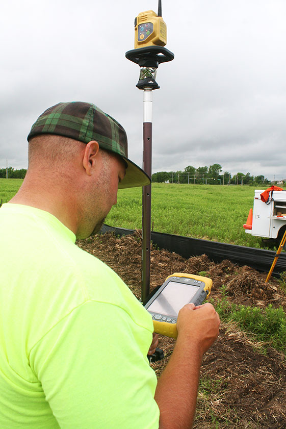
A panorama from the GNSS tide gauge at Onsala Space Observatory. When satellites pass over the sky, the GNSS tide gauge uses signals direct from the satellite and signals reflected off the sea surface to measure the sea level. Photo: Johan Löfgren
New Tide Gauge Uses GNSS to Measure Sea-Level Change
A new way of measuring and monitoring sea level — an important facet of researching climate change — has been implemented by scientists at Chalmers University of Technology in Sweden using existing coastal GPS stations.
When satellites pass over the sky, the GNSS tide gauge uses signals direct from the satellite and signals reflected off the sea surface to measure the sea level. Photo: Johan Löfgren
Measuring sea level is an increasingly important part of climate research, and a rising mean sea level is one of the most tangible consequences of climate change. Researchers at Chalmers University of Technology have studied new ways of measuring sea level that could become important tools for testing climate models and for investigating how the sea level along the world’s coasts is affected by climate change.
Johan Löfgren and Rüdiger Haas, scientists at Chalmers Department of Earth and Space Sciences, have developed and tested an instrument that measures the sea level using a GNSS tide gauge.
“The global mean sea level is rising because of climate change, but the change depends on where you are in the world,” said Rüdiger Haas. “We want to be able to make detailed measurements of sea level so that we can understand how coastal societies will be affected in the future.”
The GNSS tide gauge uses GPS and GLONASS signals. BeiDou and Galileo will be added in the future.
“We measure the sea level using the same radio signals that mobile phones and cars use in their satellite navigation systems,” said Johan Löfgren. “As the satellites pass over the sky, the instrument ‘sees’ their signals — both those that come direct and those that are reflected off the sea surface.”
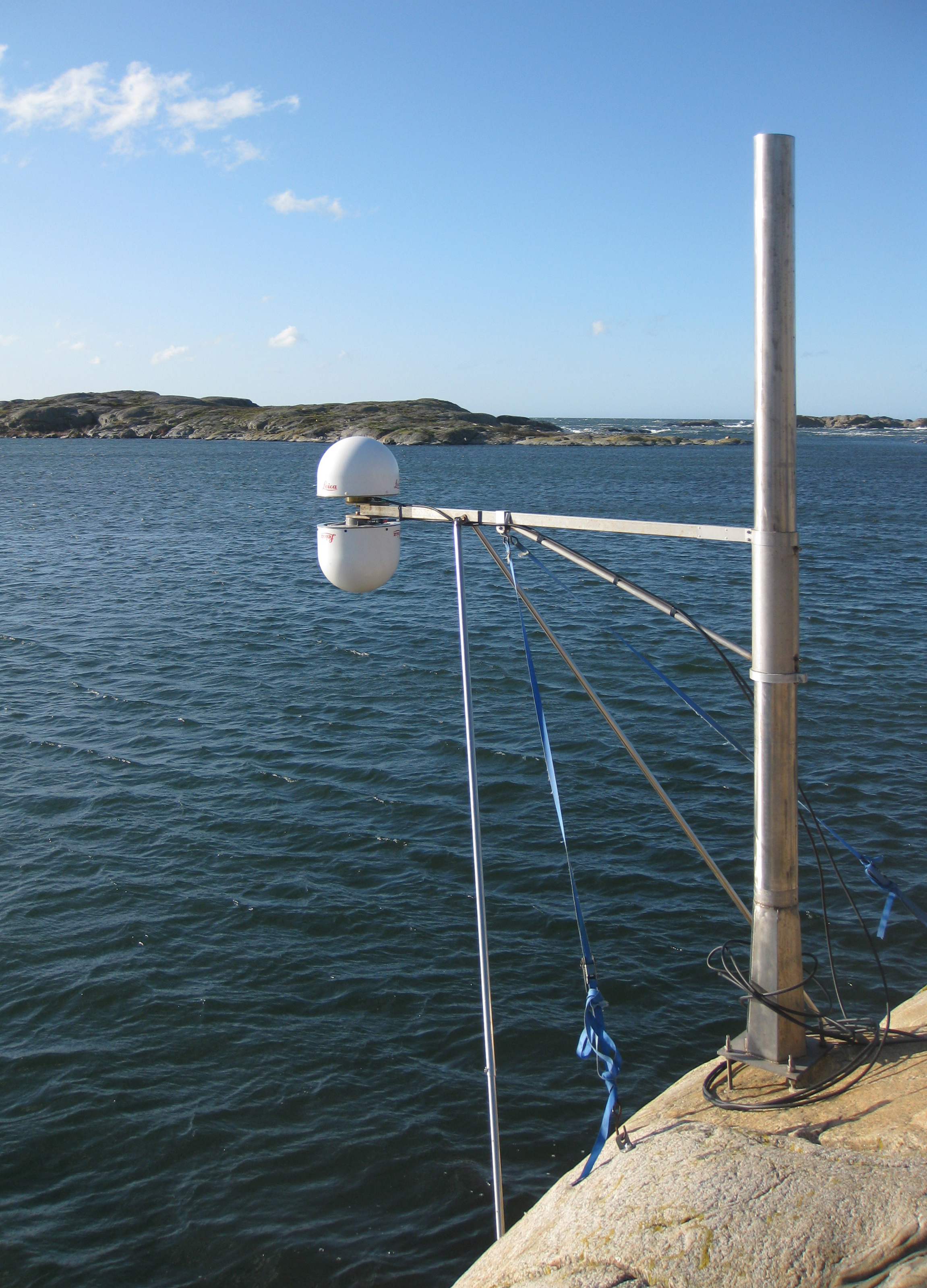
Antenna Setup. Two antennas, covered by small white radomes, measure signals both directly from the satellites and signals reflected off the sea surface. By analyzing these signals together, the sea level and its variation can be measured up to 20 times per second. The sea-level time series is rich in physical phenomena such as tides (caused mostly by the gravitational pull of the Moon and the Sun), meteorological signals (high and low pressure), and signals from climate change. Through advanced signal processing, these signals can be studied further.
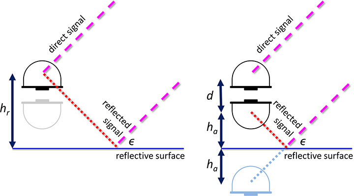
Schematic drawing of the GNSS tide gauge for SNR analysis (left) and phase-delay analysis (right). For the SNR analysis, the satellite signal with elevation ε reflects off the sea surface and interferes with the direct satellite signal at the antenna, creating an interference pattern in the recorded SNR observable that can be related to the reflector height, hr. For the phase delay analysis, the phase delays of the direct and the reflected signals are recorded separately, and through geodetic analysis of the phase delay, the baseline between the antennas can be determined and related to the height of the nadir-looking antenna over the sea surface, ha, and the vertical distance between the antenna phase centers, d.
The scientists’ initial study compared sea-level solutions from two analysis methods: signal-to-noise ratio (SNR) analysis and phase-delay analysis. The SNR analysis uses multipath signals observed with an upward-looking antenna, and the phase delay analysis uses the phase delay for both an upward- and a downward-looking antenna (see diagram).
Both GPS and GLONASS L1 and L2 signals were recorded, and the results were compared to independent measurements of sea level from a co-located pressure tide gauge. The GNSS-derived sea level showed a high correlation with the tide-gauge sea level for both analysis methods. Correlation coefficients for the phase-delay analysis and for the SNR analysis using frequency L1 were 0.95 to 0.97, whereas the correlation coefficients for the SNR analysis using frequency L2 were 0.86 to 0.87.
The phase-delay analysis shows a better agreement with the independent tide gauge sea level than the sea level from SNR analysis. Expressed as RMS differences, the phase-delay analysis achieves values of 3.5 cm (GPS) and 3.3 cm (GLONASS), whereas the SNR analysis achieves 4.0 cm (GPS) and 4.7 cm (GLONASS). The scientists concluded that, for the phase-delay analysis, it is possible to use both frequency bands, and for the SNR analysis, frequency band L2 should be avoided if other signals are available.
The GNSS tide gauge at Onsala Space Observatory uses signals from satellite navigation systems like GPS to measure the sea level. Photo: Johan Löfgren
Land and Sea. Unlike traditional tide gauges, the new GNSS tide gauge can measure changes in both land and sea at the same time, in the same location. That means both long-term and short-term land movements (post-glacial rebound and earthquakes) can be taken into consideration.
“Now we can measure the sea level both relative to the coast and relative to the center of the Earth, which means we can clearly tell the difference between changes in the water level and changes in the land,” said Johan Löfgren.
This summer, other high-precision instruments are being installed to work with the Onsala GNSS tide gauge, in collaboration with SMHI, the Swedish Meteorological and Hydrological Institute.
“Our tide gauge station will become part of a network of stations along the coast of Sweden that will be able to monitor changes in the water level to millimeter precision well into the future,” said Gunnar Elgered, professor at Chalmers Department of Earth and Space Sciences.
The scientists have also shown that existing coastal GNSS stations, installed primarily for the purpose of measuring land movements, can be used to make sea-level measurements.
“We’ve successfully tested a method where only one of the antennas is used to receive the radio signals. That means that existing coastal GNSS stations — there are hundreds of them all over the world — can also be used to measure the sea level,” said Johan Löfgren.
This work was previously reported in these publications: Larson, K.M., J. Lofgren, and R. Haas, “Coastal Sea Level Measurements Using A Single Geodetic GPS Receiver,” Adv. Space Res., Vol. 51(8), 1301-1310, 2013, doi:10.1016/j.asr.2012.04.017, 2013; and Larson, K.M., R. Ray, F. Nievinski, and J. Freymueller, “The Accidental Tide Gauge: A Case Study of GPS Reflections from Kachemak Bay, Alaska,” IEEE GRSL, Vol 10(5), 1200-1205, doi:10.1109/LGRS.2012.2236075, 2013.