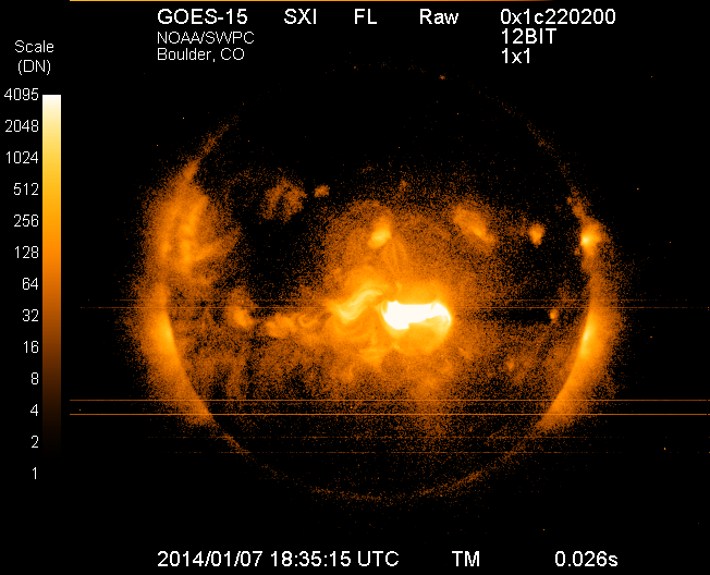
Image of the sun on Tuesday, Jan. 7, 2014, from the Solar X-Ray Imager on NOAA’s GOES satellite, taken just after the maximum emission of a solar flare. The eruption came from the middle of the sun and is directed toward Earth. This is the largest solar flare so far this year.
Forecasters at NOAA’s Space Weather Prediction Center said the sun’s coronal mass ejection (CME) that reached Earth on Jan. 9, unsettled the geomagnetic field but did not cause storm conditions to be reached due to the weak magnetic field. While there is still a chance we could see some geomagnetic storming, that threat is greatly diminished. The Space Weather Prediction Center is a division of the U.S. National Oceanic and Atmospheric Administration.
The sunspot in Region 1944 that produced the eruption at 1:32 p.m. EST Tuesday, January 7, has had no significant additional flaring and shows signs of decay.
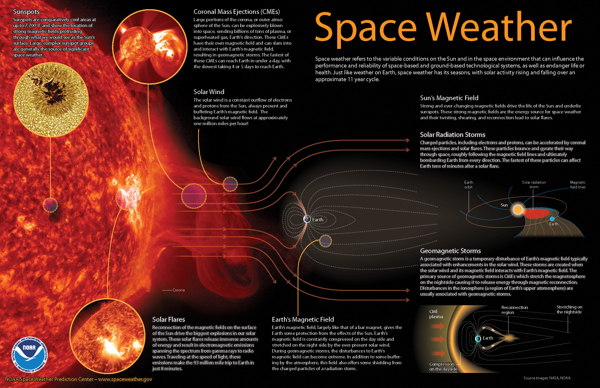
How space weather affects real-time technology
Economies around the world have become increasingly vulnerable to the ever-changing nature of the sun. Solar flares can disrupt power grids, interfere with high-frequency airline and military communications, disrupt GPS signals, interrupt civilian communications, and blanket the Earth’s upper atmosphere with hazardous radiation.
Monitoring and forecasting solar outbursts in time to reduce their effect on space-based technologies have become new national priorities. And NOAA’s Space Weather Prediction Center (SWPC), part of NOAA’s National Weather Service, is the nation’s official source of space weather forecasts, alerts, and warnings.
Space weather explained (source: NOAA).
Monitoring the Sun
To monitor events on the sun, SWPC staff utilize a variety of ground- and space-based sensors and imaging systems to view activity at various depths in the solar atmosphere. A worldwide network of USAF-sponsored optical observatories also provides space weather forecasters with detailed, plain-language information about activity in and around sunspot groups, as well as other areas of interest on the sun.
Space weather forecasters also analyze the 27-day recurrent pattern of solar activity. Based on a thorough analysis of current conditions, comparing these conditions to past situations, and using numerical models similar to weather models, forecasters are able to predict space weather on times scales of hours to weeks.
With effective alerts and warnings, NOAA is helping to minimize the hazards of space weather on technology. For example, satellite operations can be adjusted, power grids can be modified, and polar flights can be rerouted.
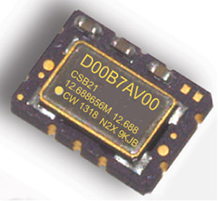
COSPAS-SARSAT beacons are battery operated emergency distress transmitters for locating ships or persons when time is critical for survival. The new Connor-Winfield series CSBxx Series are Surface Mount, 5x7mm, 3.3V, LVCMOS or Clipped Sinewave Temperature Compensated Crystal Oscillators (TCXO) designed to be emergency beacon frequency references requiring tight ± 0.2 ppm frequency stability and frequency slope control of only ±0.7 ppb/min.
The low power dissipation of 6mW allows it to power-up immediately with an accurate frequency. Class 1 devices operate over –40°C to 55°C and Class 2 devices operate–20°C to 55°C. Standard frequencies are 10.0, 12.688375, 12.688575, 12.688656, 12.68875, 16.367, and 20.0 MHz. To save time during the beacon certification process, temperature test data is available from a special on-line URL for each serialized TCXO.
Features:
3.3 Vdc Operation
Frequency Stability: ± 0.20 ppm
Mean Slope = ±0.7 ppb/min
Temperature Ranges Available:
Class I -40 to 55°C , Class II -20 to 55°C
LVCMOS or Clipped Sinewave Output
Ceramic Surface Mount Package
Tape and Reel Packaging
RoHS Compliant / Pb Free
Each unit is serialized and data is available on-line
The Director General of Civil Aviation (DGCA) of India certified on December 30 the GAGAN system to RNP0.1 (Required Navigation Performance 0.1 Nautical Mile) service level, according to The Hindu.
Now aircraft equipped with Satellite Based Augmentation System (SBAS) receivers will be able to use GPS-Aided Geo Augmented Navigation (GAGAN) signals in Indian airspace for en route navigation and non-precision approaches without vertical guidance.
Mission control centers, along with associated uplink stations, have been set up at Kundalahalli in Bangalore. Another control center and uplink station are in Delhi. A top official of the AAI said one of the Reference Stations has been housed outside the premises of the Thiruvananthapuram airport. The reference stations pick up signals from the orbiting GPS satellites. The measurements are immediately passed on to the mission control centers that then work out the necessary corrections that must be made. Messages carrying those corrections are sent via the uplink stations to the satellites in geostationary orbit that have the GAGAN payload.
The availability of the GAGAN signal in the country’s air space will bridge the gap between European Union’s European Geostationary Navigation Overlay Service (EGNOS) and Japan’s Multi-functional Satellite Augmentation System (MSAS) coverage areas.
The SBAS consists of 15 Indian Reference Stations, three Indian Navigation Land Uplink Stations, three Mission Control Centers, three Geo-Stationary Navigation Payload in C and L bands and with all the associated software and communication links.
GAGAN will provide augmentation service for GPS over India, the Bay of Bengal, South East Asia and the Middle East expanding up to Africa.
The departing Deputy Secretary of Transportation, John Porcari, wrote a letter in the closing days of 2013 opposing the U.S. Air Force’s announced plans to begin broadcasting Civil Navigation (CNAV) message-populated L2C and L5 signals as early as April 2014. Military personnel are incensed over what they see as Porcari’s impugning, when not ignoring, the Air Force 35-year track record of broadcasting the gold standard of global navigation satellite signals — something in which Transportation has zero experience.
Porcari alludes in his December 27 letter to “non-standard engineering tools” and “non-standard operations” that he believes would come into play for early CNAV broadcast. “These have the potential to inject human error, which may result in unacceptable GPS constellation operation.”
What Porcari means by “non-standard” he does not specify, although he confesses to unease as “the ability to monitor these signals, [without which] the system will not know if the L2C and LS signals are within specification. Given these risks, DOT is concerned that the CNAV messages could provide hazardously misleading information, impacting GPS safety-of-life, protection of property, and economic security applications.” The full text of the Porcari letter is available here.
In addition to questioning Air Force 2 SOPS ability to broadcast an accurate, compliant signal containing CNAV, the letter appears to ignore — or be ignorant of — the 17 official U.S. government/military monitoring sites for GPS distributed around the world, not to mention thousands of other monitoring sites run by government agencies such as the Jet Propulsion Laboratory, the National Aeronautics and Space Administration, and the National Geospatial-Intelligence Agency, and by many universities such as Stanford, Ohio State, Cal Tech, Massachusetts Institute of Technology, and many other international institutions around the world. Many of these sites collaborate under the rubric of the International GNSS Service.
Finally, two private corporations monitor and correct all GPS signals both from space and on the ground: John Deere and Trimble Navigation. Both companies run commercial, automated GPS signal monitoring systems that that report any glitch, change, power fluctuation, or anomaly in the navigation message for all GPS signals with an average two-second notification time.
“This letter is so much BS,” fumed one source who wished to remain anonymous, “coming from an agency that is in arrears in its GPS payments to the tune of more than $70 million and has no clue how to represent the global GPS user. GPS is a ubiquitous system, not just a tool for the DOT and the Federal Aviation Administration. GPS needs to implement these signals for all users and as a modernization program that was promised to be in place years ago.”
senseFly’s drones eBee and swinglet CAM, both designed for mapping missions, are now also capable of quickly taking oblique images to complement a mapping project or add additional documentation.
This patent-pending technology is based on a proprietary control algorithm that takes oblique images of photo targets without the need of a camera gimbal, enabling senseFly’s ultralight mapping drones to take aerial shots with an up to 45-degree inclination from the photo target.
The algorithms running on board the drone’s autopilot automatically place and orient the drone based on the defined image resolution and inclination (0-45°) selected by the operator. The drone then adapts its trajectory according to local wind and target altitude.
Having a system that positions the camera autonomously with respect to the photo target enables senseFly’s drone systems to take precise oblique images without the need for live video feedback or a camera gimbal.
As these new techniques do not require any hardware changes, this ability is freely available to the community of eBee and swinglet CAM (late 2012 model) users with the new release of eMotion 2.2.
Beside creating stunning visuals, senseFly’s latest release of Postflight Terra 3D will enable users to go one step further and add these oblique images to a standard mapping flight, adding visibility to facades and vertical surfaces.
Abstract submissions are now being accepted for the Institute of Navigation’s (ION) GNSS+ 2014, the 27th International Technical Meeting of the Satellite Division. The conference will take place September 8-12, 2014 (Tutorials September 8-9) at the Tampa Convention Center, Tampa, Florida.
The deadline for submitting abstracts is March 7, 2014. Instructions on submitting your abstract can be found on the ION website.
ION GNSS+ 2014 is the world’s largest technical meeting and showcase of GNSS technology, products and services and brings together international leaders in GNSS and related positioning, navigation and timing fields to present new research, introduce new technologies, update current policy, demonstrate products and exchange ideas.
This year’s conference will feature a technical program focused around six technical tracks:
Commercial Track – Manufacturers and industry experts will present the latest innovations in commercial products and services across a range of domains. The introduction of new technology to products will be covered along will the important aspects of simulation and testing.
Application Track – For researchers, manufacturers and end users to present innovative solutions or projects within a wide range of applications.
Innovations Track –The latest scientific innovations which are emerging from scientific research and developing into the products and services we will see coming to the market in the not too distant future. In addition the scientific applications of new GNSS developments and innovations will be covered.
Advanced Multi-sensor Navigation Track – Leading-edge research on multi-sensor solutions to demanding navigation and positioning challenges that GNSS cannot meet on its own. Papers are welcome on novel non-GNSS positioning technologies and their integration, both with GNSS and with each other.
Advanced Algorithms and Methods – Innovative, state-of-the-art algorithms and methods that preserve and improve GNSS PNT performance now and into the next era of multi-GNSS PNT capabilities. Papers are welcome on any algorithm/software approach to improving the robustness of current GNSS performance, as well as developments that integrate signals and measurements from emerging multi-GNSS constellations. Algorithms that address GNSS vulnerability, new and exciting GNSS applications, enhanced receiver functionality, test beds and practical implementations are encouraged.
System Updates and Modernization – Plans, Policies & Government Aspects
NEW THIS YEAR: Abstracts submitted in the Commercial and Applications tracks are eligible for presentations only in the conference proceedings (a full paper is optional but not required).Peer Review Papers – Technical papers submitted under the Advanced Multi-Sensor Navigation and Advanced Algorithms and Methods tracks are available for optional peer review. Manuscripts must be received in proper form by July 15 to be eligible for peer review.
On December 27, 2013, the first anniversary of BeiDou Navigation Satellite System providing full operational regional service was held in Beijing. At the meeting, China Satellite Navigation System Management Office Director Ran Chengqi announced the BeiDou Navigation Satellite System Public Service Performance Standard.
The document details the public service performance parameters of BeiDou system, including service area, accuracy, integrity, continuity, and availability. It is a basic commitment to customers from BeiDou system providers, but also an important basis for customers to choose, use and evaluate the system performance.
Also released is Version 2 of the BeiDou Navigation Satellite System Interface Control Document (ICD) for the Open Service Signal. Among other changes, the new version now includes a description of the B2I signal on 1207.140 MHz.
The publishing of the Public Service Performance Standard is a common practice in the world satellite navigation system suppliers, and also a prerequisite for BeiDou system involvement in international civil aviation, international maritime, 3GPP and other international standard-setting organization activities. Further, it is meaningful for the promotion of international cooperation and application of the BeiDou system in the aviation, maritime and mobile communication areas, according to the China Satellite Navigation System Management Office.
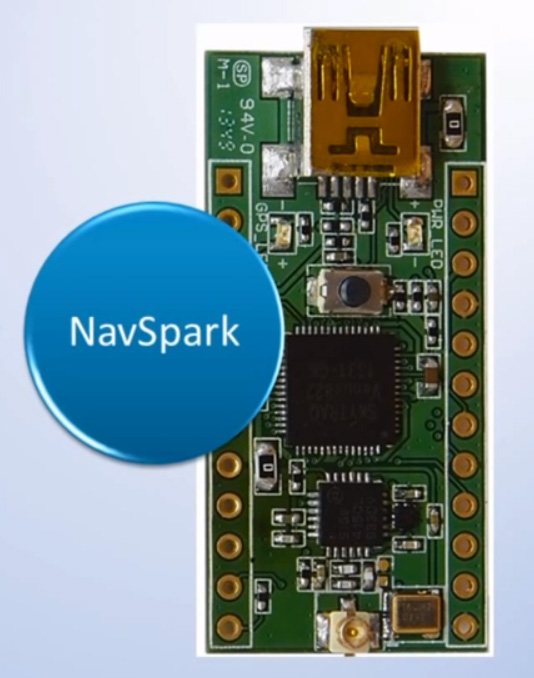
SkyTraq Technology, Inc., a fabless GNSS positioning technology company, is undertaking a crowdfunding campaign on Indiegogo to explore if there is sufficient interest in applying GPS/GNSS processor technology beyond traditional ways by offering NavSpark, a small, powerful, thumb-sized, 32-bit, microcontroller development board with GPS/GNSS receiver as onboard peripheral. With price approaching an 8-bit microcontroller development board, the GPS/GNSS receiver is effectively provided to users free of charge. They are seeking $27,000 in funding until February 6, 2014.
NavSpark features:
100MHz 32bit RISC Processor with 16Kbyte I-Cache and 2Kbyte D-Cache
IEEE-754 Compliant Floating Point Unit
1MByte Flash Memory
212Kbyte SRAM
GPS Receiver
UART x 2
SPI x 2
I2C x 1
17 Digital I/O (shared with above functional pins)
1 Pulse Per Sec Timing Reference with +/-10nsec Accuracy
Customized Arduino IDE with GPS SDK Seamlessly Integrated
NavSpark-BD model has a GPS/Beidou receiver onboard, enabling users to use the latest GPS/Beidou navigation technology just as large smartphone makers are beginning to adopt this new technology. The NavSpark-GL model has GPS/GLONASS receiver onboard, enabling users to use dual-satellite navigation technology, GPS/GLONASS as used in high-end smartphones, in their hardware projects. The NavSpark development board makes the latest global navigation satellite technology easily accessible.
SkyTraq’s 7mm x 7mm QFN56 Venus822 quad-mode GPS/GNSS processor with extended I/O pins is used on NavSpark. Venus822 is designed to simultaneously process 34 GPS/GLONASS/Beidou/Galileo/QZSS/SBAS signals in parallel, thus having much higher computation power and larger memory than conventional 8-bit or 32-bit microcontrollers. Without using GPS/GNSS function, all the 100 MIPS RISC/FPU processing power and 1 MB Flash + 212 Kb RAM memory capacity is available for user application. When just using GPS-only mode or GPS/GLONASS, GPS/Beidou dual-satellite navigation mode, the remaining MIPS and memory still far exceeds what’s available on similar small, low-cost development boards on the market.
With average price of different model variants plus active antenna in range of $15 ~ $20, NavSpark’s goal is to provide the makers an alternative powerful, small development board with location-sensing capability, and at the same time making latest GPS/Beidou or GPS/GLONASS dual-satellite navigation technology as easily accessible as GPS to the users worldwide.
NavSpark is low cost enough to leave in small hardware projects. For higher volume projects such as asset tracker, GPS fitness product, sports performance logger, toy quad-copter autopilot, etc., after rapid prototyping using NavSpark, volume usage can later change to 10mm x 10mm x 1.3mm Venus838FLPx module, a miniaturized LGA version of NavSpark. For applications benefiting from NavSpark’s high processing power and large memory without using GPS/GNSS, volume usage can later change to Venus822 chip to lower cost.
Hemisphere GNSS, Inc. today announced that Chuck Joseph has been named president and chief executive officer, effective immediately, replacing Phil Gabriel. Joseph has also been appointed to the Hemisphere GNSS Board of Directors.
Joseph has more than 30 years of executive leadership across multiple industries, serving in corporate officer and board of director capacities. He has extensive proven experience in GNSS OEM and direct sales market segments including survey and mapping, GIS, machine control, marine, avionics, personal (mobile) navigation, and tracking systems.
Before joining Hemisphere GNSS, Joseph most recently served as president and chief operating officer of nusola, Inc., an energy technology company he co-founded and where he continues to serve as executive chairman of the Board. Previously, among other roles, Joseph was senior vice president and general manager of Immersion Corporation, a tactile feedback technology company focused on GPS-centric mobile and industrial applications, corporate vice president of marketing and sales for Magellan Corporation, and executive vice president and general manager of Trimble Navigation.
“Chuck is a proven executive with the experience and expertise to lead Hemisphere GNSS as we enter our next phase of growth and development,” said Jonathan Ladd, chairman of the Hemisphere GNSS Board of Directors. “Over the course of his career, Chuck has repeatedly demonstrated the ability to develop critical corporate strategies to help innovative companies scale and grow globally. His understanding of our business, significant international experience, and deep OEM and GNSS industry experience make him ideally suited to lead Hemisphere as we seek to accelerate company growth.”
“Hemisphere has long been recognized for its pioneering and trend setting high-precision GNSS technology, and I look forward to leading the company’s talented team as we make the strategic decisions necessary to expand our market share and OEM presence globally,” Joseph said. “Leveraging our deep GNSS experience and strong, core GNSS technologies, along with UniStrong’s high quality, low-cost product design and development resources, Hemisphere is poised for significant global growth.”
In conjunction with the reported change in management, Hemisphere GNSS is also announcing the departure of Phil Gabriel, the company’s previous president, effective today. Ladd commented, “Phil was instrumental in getting our company off the ground after the acquisition from AgJunction Inc. in early 2013. We thank Phil for his contributions and dedication during the past year, and wish him good fortune and success on his next endeavor.”
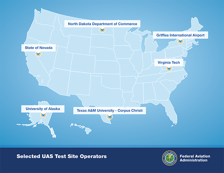
After a rigorous 10-month selection process involving 25 proposals from 24 states, the Federal Aviation Administration announced it has chosen six unmanned aircraft systems (UAS) research and test site operators across the country.
According to the announcement, in selecting the six test site operators, the FAA considered geography, climate, location of ground infrastructure, research needs, airspace use, safety, aviation experience and risk. In totality, these six test applications achieve cross-country geographic and climatic diversity and help the FAA meet its UAS research needs.
A brief description of the six test site operators and the research they will conduct into future UAS use are below:
University of Alaska. The University of Alaska proposal contained a diverse set of test site range locations in seven climatic zones as well as geographic diversity with test site range locations in Hawaii and Oregon. The research plan includes the development of a set of standards for unmanned aircraft categories, state monitoring and navigation. Alaska also plans to work on safety standards for UAS operations.
State of Nevada. Nevada’s project objectives concentrate on UAS standards and operations as well as operator standards and certification requirements. The applicant’s research will also include a concentrated look at how air traffic control procedures will evolve with the introduction of UAS into the civil environment and how these aircraft will be integrated with NextGen. Nevada’s selection contributes to geographic and climatic diversity.
New York’s Griffiss International Airport. Griffiss International plans to work on developing test and evaluation as well as verification and validation processes under FAA safety oversight. The applicant also plans to focus its research on sense and avoid capabilities for UAS and its sites will aid in researching the complexities of integrating UAS into the congested, northeast airspace.
North Dakota Department of Commerce. North Dakota plans to develop UAS airworthiness essential data and validate high reliability link technology. This applicant will also conduct human factors research. North Dakota’s application was the only one to offer a test range in the Temperate (continental) climate zone and included a variety of different airspace which will benefit multiple users.
Texas A&M University – Corpus Christi. Texas A&M plans to develop system safety requirements for UAS vehicles and operations with a goal of protocols and procedures for airworthiness testing. The selection of Texas A&M contributes to geographic and climactic diversity.
Virginia Polytechnic Institute and State University (Virginia Tech). Virginia Tech plans to conduct UAS failure mode testing and identify and evaluate operational and technical risks areas. This proposal includes test site range locations in both Virginia and New Jersey.
Across the six applicants, the FAA is confident that the agency’s research goals of System Safety & Data Gathering, Aircraft Certification, Command & Control Link Issues, Control Station Layout & Certification, Ground & Airborne Sense & Avoid, and Environmental Impacts will be met.
Each test site operator will manage the test site in a way that will give access to parties interested in using the site. The FAA’s role is to ensure each operator sets up a safe testing environment and to provide oversight that guarantees each site operates under strict safety standards.
From the start, the FAA recognized it was important to have requirements ensuring that privacy and civil liberties are protected at the test sites. Among other requirements, test site operators must comply with federal, state, and other laws protecting an individual’s right to privacy, have publicly available privacy policies and a written plan for data use and retention, and conduct an annual review of privacy practices that allows for public comment.
Under the current law, test site operations will continue until at least February 13, 2017.
The implementation changes and first live tests of BeiDou and Galileo on Teseo-3 GNSS chips developed in 2013 are covered, bringing it to a four-constellation machine. By 2020, we expect to have four global constellations all on the same band, giving us more than 100 satellites — under clear sky, as many as 30 or 40 simultaneously.
By Philip G. Mattos and Fabio Pisoni
Multi-constellation GNSS first became widely available in 2010/2011, but only as two constellations, GPS+GLONASS. Although receivers at that time may have supported Galileo, there were no usable satellites. BeiDou was a name only, as without a spec (an interface control document, or ICD), no receivers could be built. However, the hardware development time of receivers had been effectively shortened: the Galileo ICD had been available for years, BeiDou codes had been reverse-engineered by Grace Gao and colleagues at Stanford, and at the end of 2011 they were confirmed by the so-called test ICD, which allowed signal testing without yet releasing message characteristics or content.
The last weeks of 2012 saw two great leaps forward for GNSS. Galileo IOV3 and 4 started transmitting at the beginning of December, bringing the constellation to four and making positioning possible for about two hours a day. At the end of December, the Chinese issued the BeiDou ICD, allowing the final steps of message decode and ephemeris calculation to be added to systems that had been tracking BeiDou for many months, and thus supporting positioning. The Teseo-2 receiver from STMicroelectronics has been available for some years, so apart from software development, it was just waiting for Galileo satellites; however, for BeiDou it needed hardware support in the form of an additional RF front end. Additionally, while it could support all four constellations, it could not support BeiDou and GPS/Galileo at the same time, as without the BeiDou ICD the spreading codes had to be software-generated and used from a memory-based code generator, thus blocking the GPS/Galileo part of the machine.
The Teseo-3 receiver appeared late in 2013, returning to the optimum single-chip form factor: RF integrated with digital silicon and flash memory in the same package, enabling simultaneous use of BeiDou and GPS/Galileo signals. Multi-constellation in 2012 was GPS+GLONASS, which brought huge benefits in urban canyons with up to 20 visible satellites in an open sky. Now, for two hours a day in Europe while the Galileo IOVs are visible, we can run three constellations, and in the China region, GPS/BeiDou/Galileo is the preferred choice.
This article covers the first tracking of four Galileo satellites on December 4, 2012, first positioning with Galileo, and first positioning with BeiDou in January 2013. It will cover static and road tests of each constellation individually and together as a single positioning solution. Road tests in the United States/Europe will combine GPS/GLONASS/Galileo, while tests in the China region will combine GPS/Galileo/BeiDou. Results will be discussed from a technical point of view, while the market future of multi-constellation hardware will also be considered.
In the 2010–2020 timeframe, GLONASS and BeiDou (1602 MHz FDMA and 1561 MHz respectively) cost extra silicon in both RF and digital hardware, and cause marginal extra jamming vulnerability due to the 50 MHz bandwidth of the front end. The extra silicon also causes extra power consumption.
After 2020, GLONASS is expected to have the L1OC signal operational, CDMA on the GPS/Galileo frequency, and BeiDou is expected both to have expanded worldwide, and also to have the B3 signal fully operational, again on 1575 MHz. At that point we will have four global constellations all on the same band, giving us more than 100 satellites. With a clear sky, the user might expect to see more than 30, sometimes 40, satellites simultaneously.
Besides the performance benefits in terms of urban canyon availability and accuracy, this allows the receiver to be greatly simplified. While code generators will require great flexibility to generate any of the code families at will, the actual signal path will be greatly simplified: just one path in both RF (analog) and baseband (digital) processing, including all the notch filters, derotation, and so on. And this will greatly reduce the power consumption.
Will the market want to take the benefit in power consumption and silicon area, or will it prefer to reuse those resources by becoming dual-frequency, adding also the lower-L-band signals, initially L5/E5, but possibly also L2/L3/L6 ? The current view is that the consumer receiver will go no further than L5/E5, but that the hooks will be built-in to allow the same silicon to be used in professional receivers also, or in L2C implementations to take advantage of the earlier availability of a full constellation of GPS-L2C rather than GPS-L5.
This article presents both technical results of field trials of the quad-constellation receiver, and also the forward looking view of how receivers will grow through multi-frequency and shrink through the growing signal commonalities over this decade.
History
Galileo was put into the ST GPS/GNSS receiver hardware from 2006 to 2008, with a new RF and an FPGA-based baseband under the EU-funded GR-PosTer project. While a production baseband (Cartesio-plus) followed in high volume from 2009, in real life it was still plain GPS due to the absence of Galileo satellites.
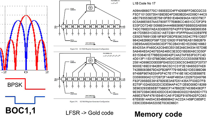
The changed characteristics in Galileo that drove hardware upgrades are shown in Figure 1. The binary offset carrier BOC(1,1) modulation stretches the bandwidth, affecting the RF, while both the BOC and the memory codes affect the baseband silicon in the code-generator area.
Figure 1. Changes for Galileo.
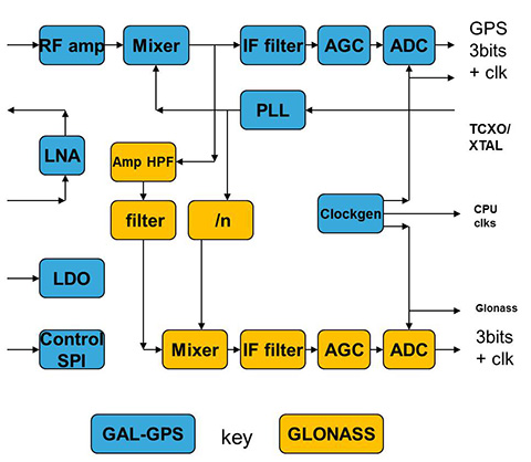
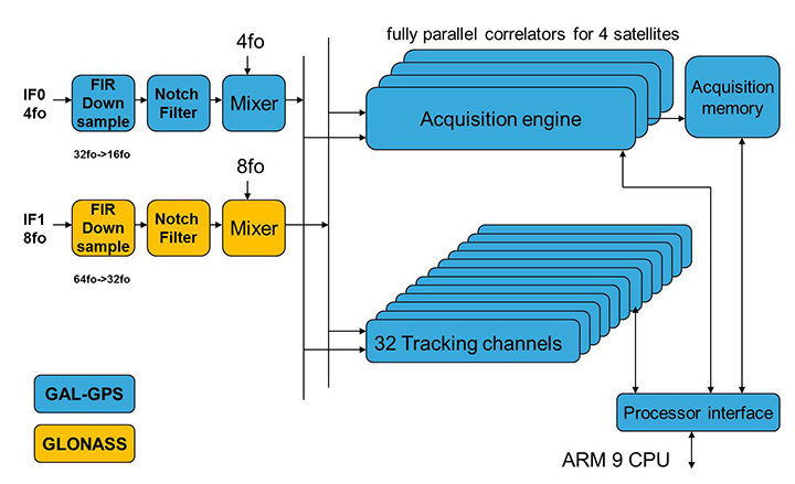
Next was the return to strength of the GLONASS constellation, meaning receivers were actually needed before Galileo. However the different center frequency (1602 MHz), and the multi-channel nature of the FDMA meant more major changes to the hardware. As shown in Figure 2 in orange, a second mixer was added, with second IF path and A/D converter.
Figure 2. Teseo-2 RF hardware changes for GLONASS.Figure 3. Teseo-2 and Teseo-3 baseband changes for GLONASS.
The baseband changes added a second pre-processing chain and configured all the acquisition channels and tracking channels to flexibly select either input chain. Less visible, the code-generators were modified to support 511 chip codes and 511kchips/sec rates.
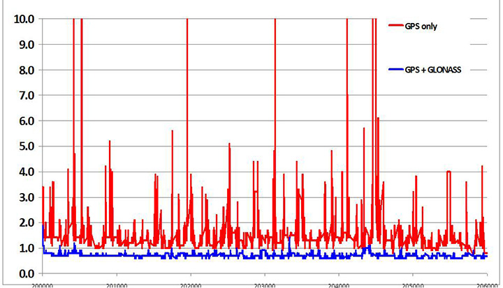
Teseo-2 appeared with GPS/GLONASS support in 2010, and demonstrated the benefit of GNSS in urban canyons, as shown by the dilution of precision (DOP) plot for central London in Figure 4. The GPS-only receiver (in red) has frequent DOP excursions beyond limits, resulting either in bad accuracy or even interrupted fix availability. In contrast, the GNSS version (in blue) has a DOP generally below 1, with a single maximum of 1.4, and thus 100 percent availability. Tracking 16 satellites, even if many are via non-line-of-sight (NLOS) reflected paths, allows sophisticated elimination of distorted measurements but still continuous, and hence accurate, positioning.
Figure 4. DOP/accuracy benefits of GNSS.
BeiDou
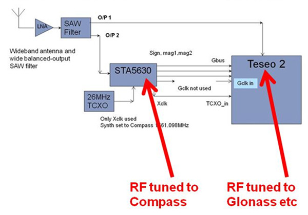
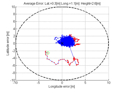
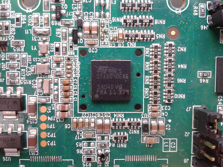
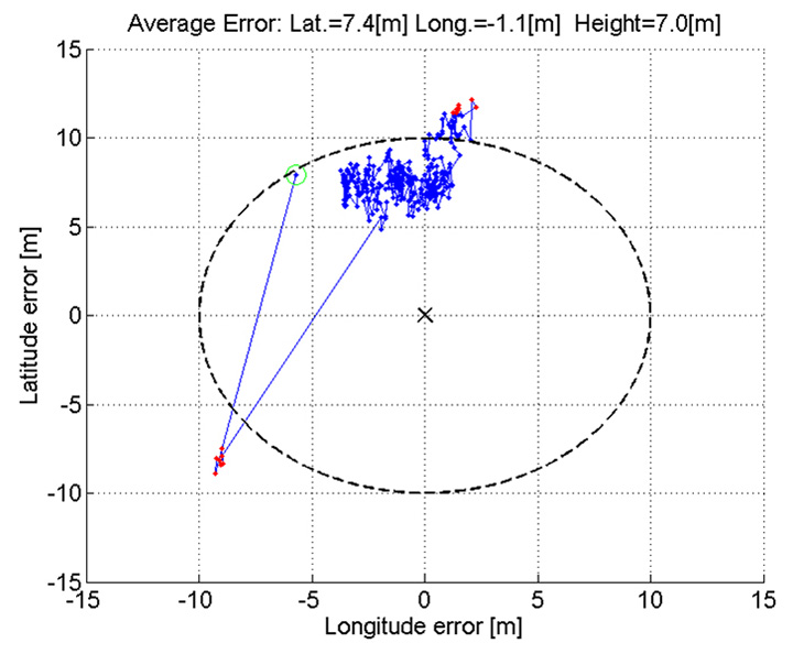
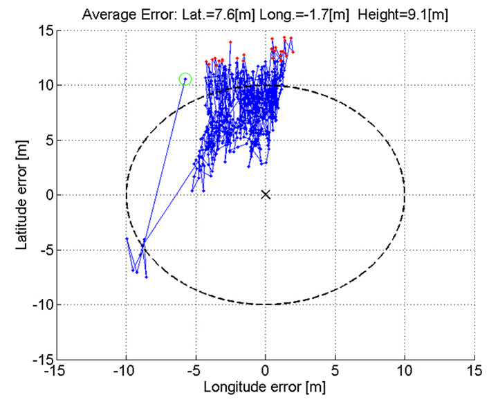
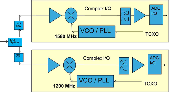
Like Galileo, BeiDou is a story of chapters. Chapter 1 was no ICD, and running on a demo dual-RF architecture as per the schematic shown in Figure 5. Chapter 2 was the same hardware with the test ICD, so all satellites, but still no positioning. Chapter 3 was the full ICD giving positioning in January 2013 (Figure 6), then running on the real Teseo-3 silicon in September 2013, shown in Figure 7.
Figure 5. Demo Teseo-2 dual RF implementation of BeiDou.Figure 6. Beidou positioning results.Figure 7. Teseo 3 development board.
The Teseo-3 has an on-chip RF section capable of GPS, Galileo, GLONASS and BeiDou, so no external RF is needed.
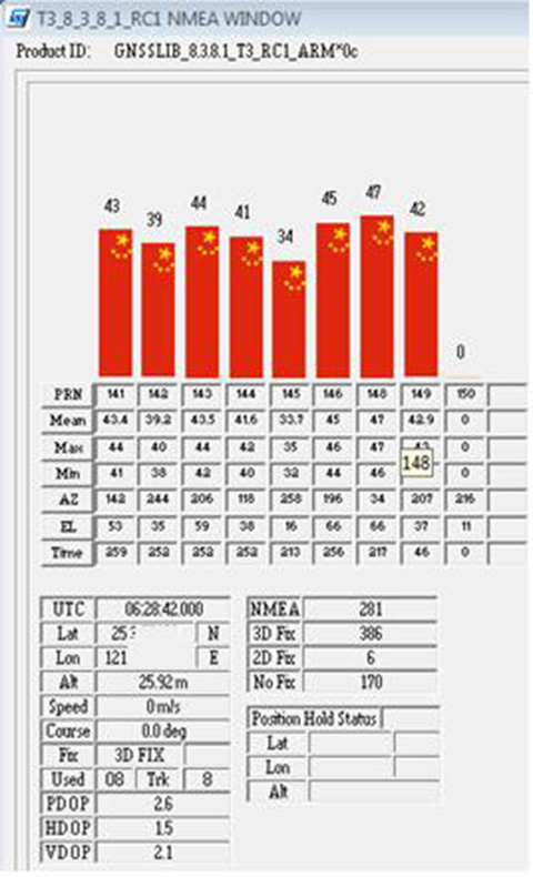
The clear green space around the Teseo-3 chip in the photo and the four mounting holes are for the bolt-down socket used to hold chips during testing, while the chip shown is soldered directly to the board. Figure 8A shows the development board tracking eight BeiDou satellites visible from Taiwan.
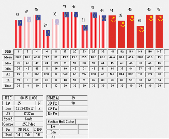
However, the silicon is not designed to be single-constellation; it is designed to use all the satellites in the sky. Figure 8b shows another test using GPS and BeiDou satellites simultaneously.
Figure 8A. Beidou.Figure 8b. GPS+Beidou.
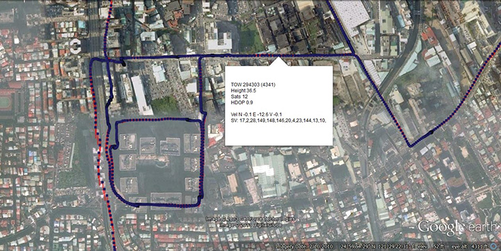
A mobile demo on the Teseo-3 model is shown running GPS plus BeiDou in Figure 9, a road test in Taipei. Satellites (SV) up to 32 are GPS, those over 140 are BeiDou, in the status window shown: total 13 satellites in a high-rise city area, though many are non-LOS.
Figure 9. GPS + Beidou roadtrack in Taipei.
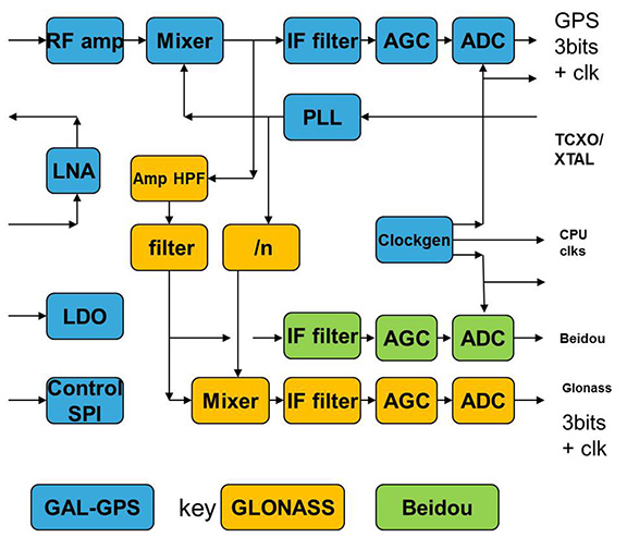
Extending the hardware to add BeiDou, which is on 1561 MHz and thus a third center frequency, meant adding another path through the IF stages of the on-chip radio. After the first mixer, GPS is at 4 MHz, and GLONASS at about 30 MHz, but BeiDou is at minus 10 MHz. While the IF strip in general is real, rather than complex (IQ), the output of the mixer and input to the first filter stage is complex, and thus can discriminate between positive frequencies (from the upper sideband) and negative ones (from the lower sideband), and this is normally used to give good image rejection. In the case of BeiDou, the filter input is modified to take the lower sideband, that is, negative frequencies, and a second mixer is not required; the IF filter is tuned to 10 MHz. The new blocks for BeiDou are shown in green in Figure 10. The baseband has no new blocks, but the code generator has been modified to generate the BeiDou codes (and, in fact, made flexible to generate many other code types and lengths). Two forms of Teseo-3 baseband are envisaged, the first being for low-cost, low-current continues to have two input paths, so must choose between GLONASS and BeiDou as required. A future high-end model may have an extra input processing path to allow use of BeiDou and GLONASS simultaneously.
Figure 10. Teseo-3 RF changes for Beidou shown in green.
Galileo Again
Maintaining the chronological sequence, Galileo gets a second chapter in three steps. In December 2012, it was possible for the first time to track four IOV satellites simultaneously, though not to position due to the absence of valid orbit data. In March 2012, it was possible for the first time to demonstrate live positioning, and this was done using Teseo-2 simultaneously by ESA at ESTEC and STMicro in Naples and Milan, our software development centres.
The demos were repeated in public for the press on July 24, 2013, at Fucino, Italy’s satellite earth station, with ESA/EC using the test user receiver (TUR) from Septentrio, and ST running simultaneous tests at its Italian labs. Figure 11 and Figure 12 show the position results for the data and pilot channels respectively, with independent LMS fixes. In real life, the fixes would be from a Kalman filter, and would be from a combined E1-B/E1-C channel, to take advantage of the better tracking on the pilot.
Good accuracy is not expected from Galileo at this stage. The four satellites, while orbited to give good common visibility, do not also give a good DOP; the full set of ground monitoring stations is not yet implemented and cannot be well calibrated with such a small constellation. Finally, the ionospheric correction data is not yet available. Despite these problems, the residuals on the solutions, against a known fixed position for the rooftop antenna, are very respectable, shown in Figure 13.
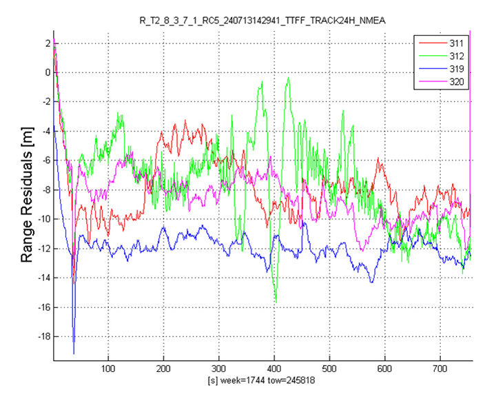
Figure 13. Galileo residuals, L1-B.
The common mode value is unimportant, representing only an offset in the receiver clock, and 10 meters is about 30 nanoseconds. The accuracy indicator is the spread between satellites, which is very respectable for a code-only receiver without full iono correction, especially around 640 on the TOW scale, where it is less than 2 meters. The rapid and major variation on the green data around t=400 is considered to be multipath, as the roof antenna is not ideally positioned with respect to other machinery and equipment also installed on the roof.
QZSS and GPS-III/L1C
Teseo-2 has supported the legacy (C/A code) signal on QZSS for some time, but Teseo-3 has been upgraded to handle the GPS-III/L1-C signal, waiting for modernized GPS. This signal is already available on the QZSS satellite, allowing tests with real signals. Significant changes were required in the baseband hardware, as the spreading code is a Weill code, whose generation complexity is such that it is generated once when the satellite is selected, then replayed real time from memory. Additionally it is long, in two domains. It is 10230 chips — that is, long to store but also long in time, with a 10-millisecond epoch. On Teseo-3, the legacy C/A code is used to determine code-phase and frequency before handing over to the Weill code for tracking.
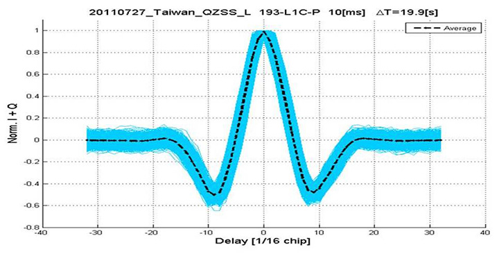
Using a long-range crystal ball and looking far into the future, a model of the future Teseo-4 DSP hardware is available, with 64 correlation taps per satellite. Running this on the captured QZSS L1-C signal gives the correlation response shown in Figure 14. Having multiple taps removes all ambiguity from the BOC signal, simultaneously removing data transitions, which can alternatively be pre-stripped using the known pilot secondary code (which on GPS III is 5 dB stronger than the data signal). The resultant plot represents 2,000 epochs, each of 10 milliseconds, plotted in blue, with integrated result for the full 20 seconds shown in the black dashed line. Assuming vehicle dynamics is taken out using carrier Doppler, this allows extremely precise measurement of the code phase, or analysis of any multipath in order to remove it. This RF data was captured on a benign site with a static antenna, so it shows little distortion.
Figure 14. L1-C tracking on QZSS satellite.Figure 15. Dual RF implementation of dual-band front end.
The Future
Having already built in extreme flexibility to the code generators to support all known signals and generalized likely future ones, the main step for the future is to support multiple frequencies, starting with adding L5 and/or L2, but as before, ensuring that enough flexibility is built in to allow any rational user/customer choice. It is not viable for us to make silicon for low-volume combinations, nor to divide the overall market over different chips. Thus our mainstream chip must also support the lower volume options.
We cannot, however, impose silicon area or power consumption penalties on the high-volume customer, or he will not buy our product.
Thus, our solution to multi-frequency is to make an RF that can support either band switchably, with the high band integrated on the volume single-chip GNSS. Customers who also need the low band can then add a second RF of identical design externally, connected to the expansion port on the baseband, which has always existed for diagnostic purposes, and was how BeiDou was demonstrated on T2. By being an RF of identical design to the internal one, it incurs no extra design effort, and would probably be produced anyway as a test chip during the development of the integrated single-chip version. Without this approach, the low volume of sales of a dual-band radio, or a low-band radio, would never repay its development costs.
Conclusions
All four constellations have been demonstrated with live satellite signals on Teseo-2, a high-volume production chip for several years, and on Teseo-3 including use in combinations as a single multi-constellation positioning solution. With the advent of Teseo-3, with optimized BeiDou processing and hardware support for GPS-3/L1C, a long-term single-chip solution is offered.
For the future, dual-frequency solutions are in the pipeline, allowing full advantage of carrier phase, and research into moving precise point positioning and real-time kinematic into the automotive market for fields such as advanced driver-assistance systems.
Acknowledgments
Teseo III design and development is supported by the European Commission HIMALAYA FP-7 project.
This article is based on a technical paper first presented at ION-GNSS+ 2013 in Nashville, Tennessee.
ST GPS products, chipsets and software, baseband and RF are developed by a distributed team in: Bristol, UK (system R&D, software R&D; Milan, Italy (Silicon implementation, algorithm modelling and verification); Naples, Italy (software implementation and validation); Catania, Sicily, Italy (Galileo software, RF design and production); Noida, India (verification and FPGA). The contribution of all these teams is gratefully acknowledged.
Philip G. Mattos received an external Ph.D. on his GPS work from Bristol University. Since 1989 he has worked exclusively on GNSS implementations, RF, baseband and applications. He is consulting on the next-generation GNSS chips, including one-chip GPS (RF+digital), and high-sensitivity GPS and Galileo for indoor applications, and combined GPS/Galileo/GLONASS chipsets. In 2008-2009, he re-implemented LORAN on the GPS CPU, and in 2009-2010 led the GLONASS implementation team. He is leading the team on L1C and BeiDou implementation, and the creation of totally generic hardware that can handle even future unknown systems.
Fabio Pisoni has been with the GNSS System Team at STMicroelectronics since 2009. He received a master’s degree in electronics from Politecnico di Milano, Italy, in 1994. He was previously with the GNSS DSP and System Team in Nemerix SA and has earlier working experience in communications (multi-carrier receivers).