GeoEye, Inc. announced that it is proposing to acquire DigitalGlobe, Inc. The combined company would create the world’s largest fleet of high resolution commercial imagery satellites.
The new company would be well-positioned to meet the evolving needs of the U.S. government and other customers in this fiscally constrained environment. We will also continue to invest in new information, analytic services and the most technologically advanced commercial satellites for government and commercial customers around the world.
Matt O’Connell, chief executive officer and president of GeoEye, said, “This proposal delivers exceptional value for the combatant commanders, national decision makers, civil users and disaster relief workers, who have a critical need for unclassified commercial imagery. It also provides benefits for the taxpayer. It offers our Government a way to get the information it needs while still reducing its funding obligations. The synergies in the combination will also benefit the shareholders of both companies.”
O’Connell continued, “In the face of significant pressure on the U.S. defense budget and intensifying international competition, a combined company will be better positioned to provide the U.S. government with the time-sensitive geospatial intelligence that is needed to support its mission in a very cost-effective manner during these fiscally conservative times. The government is looking to its providers for innovative solutions, and we believe this is the best option to achieve that.”
The proposed transaction would give DigitalGlobe shareholders $17.00 per share in total consideration, payable $8.50 per share in cash and $8.50 in GeoEye stock, or 0.3537 shares of GeoEye stock for each share of DigitalGlobe stock. This price represents a 26% premium to DigitalGlobe’s closing share price on May 3, 2012. The proposal is structured to provide DigitalGlobe shareholders with the opportunity to participate in the dynamic future growth of the combined company.
The following is a copy of a letter that GeoEye sent to DigitalGlobe with respect to its proposal:
May 4, 2012
Jeffrey R. Tarr
President and Chief Executive Officer
DigitalGlobe, Inc.
1601 Dry Creek Drive, Ste. 260
Longmont, CO 80503
Dear Jeff:
During the past few months, we have discussed with you a combination of GeoEye and DigitalGlobe. We both appreciate that a combination of our two companies results in greater capability to meet national security needs, is more cost effective to the government during this fiscally constrained period, and provides improved value to decision-makers and warfighters.
The considerable scale of the combined entity creates a strong domestic player in satellite imagery which could compete more effectively with foreign providers. The combination also allows for operating expense synergies and reduced capital requirements while better satisfying customer needs. Your letter from March 2, 2012 conveys this same sentiment:
“…we do agree that a well-managed combined company would enjoy material scale and scope benefits in addition to significant cost savings and would be well positioned to meet the needs of the US Government and other customers.”
We both acknowledge that there have been rumors and speculation regarding cuts. Given this uncertain political and fiscal climate, we believe it is in our mutual interest to provide our customers with creative solutions to problems rather than passively speculate on one or another outcome.
To that end, we propose that GeoEye acquire DigitalGlobe in a friendly transaction whereby DigitalGlobe shareholders would receive $17.00 per share in total consideration. Such consideration will be payable as $8.50 per share in cash and $8.50 in GeoEye stock (DigitalGlobe shareholders would receive 0.3537 shares of GeoEye stock for each share of DigitalGlobe owned). This price represents a 26% premium to DigitalGlobe’s closing share price on May 3, 2012. In addition, our Board of Directors would consider restructuring our proposal to increase the cash consideration up to 100% of the purchase price or, in the alternative, reducing the cash consideration and increasing the stock portion of our offer.
Given our financial strength and longstanding supportive banking relationships, we are highly confident that financing will not represent an impediment to the consummation of the proposed transaction. To provide further certainty to the DigitalGlobe Board of Directors, we have been advised that affiliates of Cerberus Capital Management, L.P., our largest shareholder, are prepared to contribute substantial capital in support of our proposed transaction.
We believe that your shareholders and your Board will agree that this is a compelling proposal.
Our Board has authorized this proposal. We are prepared to move quickly to execute a mutually acceptable definitive agreement. Our offer is subject to satisfactory due diligence, the receipt of U.S. Government approvals, and final Board and shareholder approvals.
We have already undertaken extensive due diligence on DigitalGlobe’s public filings and are now prepared to undertake a mutual detailed due diligence review at your earliest convenience. We believe that with your cooperation, we can complete this detailed due diligence and execute a definitive agreement promptly.
Finally, it is our view that a combination of our companies would have no significant contingencies and that this transaction will be promptly consummated. Our counsel, with the assistance of a highly regarded economist, has undertaken a preliminary review of antitrust and international competition issues attendant to the proposed combination, and believe that, with U.S. Government customer support, the transaction will not involve undue delay. We understand from your communications to us that you and your advisors agree.
We have engaged Goldman, Sachs & Company, Convergence Advisors LLC and Latham & Watkins LLP to advise us in this transaction.
We look forward to a response to this letter and sincerely hope that we may move forward to a negotiated transaction.
The European Commission announced a September 28 launch date for the next pair of Galileo satellites. These will launch together on a Soyuz rocket from French Guiana, joining the two Galileo in-orbit validation (IOV) satellites already in space.
The new launch will take place within a year of the flight of the first two Galileo IOV satellites, which reached orbit on October 21, 2011.
The September launch will bring the nascent constellation to four, representing the minimum needed under optimal circumstances for satellite navigation — to measure latitude, longitude and altitude while checking ranging accuracy. Therefore, according to the EC statement, these four Galileo IOV satellites can be used to assess the performance of Galileo’s global ground system, which serves to maintain the precision of the Galileo system.
In addition, manufacturers worldwide should be able to realistically test prototype Galileo-based receivers and services against actual satellite signals.
One of the long-standing issues for support of IIA vehicles after the future GPS Operational Ground Control Segment’s (OCX’s) ready-to-operate (RTO) date, which should fall in December 2016 at the latest, is what ground command-and-control (C2) system will steer GPS IIA satellites, do navigation uploads, and so on. The issue is that AEP, the current C2 system, will no longer be available once the transition to OCX takes place, and OCX has no requirement to control IIA satellites.
The OCX program, which struggled early, is now under new Program leadership within Raytheon Space Systems, and while Ray Kolibaba, the new OCX program manager, is making great progress, OCX does not need to be burdened with additional requirements at this stage of the program.
Just how big an issue is GPS IIA C2? Initially the Aerospace projections were that there would only be one or two GPS IIAs left on orbit in 2017, and it was not worth the costs to include the C2 software for the legacy system in the new software code. However, I have long maintained that Aerospace and Space Missile Systems Command (SMC) neglected to count the residual satellites, maintained by Launch, Anomaly, and Disposal Operations (LADO), which might very well actually amount to 3–4 additional IIAs. Added to the two IIAs on orbit, this could amount to six IIA SVs that need to be maintained.
The solution announced during the National Space Symposium (NSS, April 16–19) by General William Shelton, the four-star chief of Air Force Space Command, is to fund the current LADO operator, Braxton Technologies, to build in this support for the IIAs. This is significant for several reasons: One of course is that it solves the IIA C2 issues, it does it now, and at a relatively modest cost, and it utilizes more of the capabilities of the Braxton Technologies’ LADO software. Additionally it provides a true backup capability for assets on orbit that become increasingly valuable as the number of available launch slots for GPS decreases.
Braxton Technologies initially demonstrated this capability years ago in a lifeboat drill during the transition to AEP, but the navigation upload capability was never maintained for LADO after the successful transition. This is certainly a step in the right direction and provides a simple solution to a vexing problem that has plagued the GPS program for the last several years.
Dual Launch. I asked General Shelton if he would support an approach that would allow the United States to go to dual launch of GPS III on vehicles 5–6 instead of waiting until 8–9 as planned today. He said the Air Force would certainly support that, and is looking at making it possible with vehicle 7 currently. That will come even sooner if the program advances with glitches.
I also asked him about the gap between GPS III launch and OCX RTO. The gap seems to be getting wider, not narrower, and he agreed that OCX could probably not move to the left, and GPS III has moved significantly to the left, so this is still an issue that needs to be addressed. There are plans in place, but the recent budget activity has caused some uncertainty.
Sequestration. On the subject of sequestration — a highly charged Congressional effort to force another $500 billion-plus in additional defense cuts — General Shelton said it would amount come on top of the approximately $487 billion already cut from programs, and that many space programs might be unsustainable in their current mode if that occurs.
However, the U.S. Armed Services have been informed by the White House Office of Management and Budget not to make plans for sequestration. So right now, the services and other agencies of the U.S. government have been forbidden to make programmatic decisions based on a possible sequestration. Interesting.
By the way, attendance at NSS this year surpassed 9,000.
Trimble introduced a new version of the Spectra Precision Laser DDS300 Depth Display System, a laser-referenced grade control solution targeted for compact machines. The DDS300 version 3.0 introduces a new environmentally-rated control box and new level of productivity for mini-excavators and backhoe loaders used for excavation and trenching work for basements, footers, utility lines and conduit. Cable-free components, simple installation and an affordable price make the DDS300 system ideal for contractors who want to improve accuracy, fuel usage and safety of their excavation operations.
According to the announcement, the DDS300 system utilizes wireless communications, a laser receiver and angle sensors to provide dynamic positioning information for the excavator or backhoe bucket at all times. Real-time grade guidance is displayed on the 7-inch in-cab display, allowing the operator to work faster and with better accuracy. Accurate positioning of the bucket also improves the safety of excavation by eliminating the need for a grade checker to work in the trench or machine swing area.
The new waterproof and sunlight-readable CB310 Control Box display is included in the DDS300 system and is rated IP-64, making it suitable for use in bright sun or inclement weather.
Reports in daily news media such as the Washington Post and DenverPost that “Lockheed Martin will lose its entire fee of about $70 million to defray an 18 percent cost overrun” on GPS III satellites misconstrue the facts.
Don Jewell, contributing editor for GPS World, said after informal talks with key Lockheed executives, “This is a good story, but it has been sensationalized.”
Lockheed Martin’s fee is 5 percent of the target cost, which includes one-time engineering tasks, test equipment, and satellite assembly, according to the Air Force.
The first GPS III satellite remains on schedule to be available for launch in 2014, Lockheed Martin spokesman Michael Friedman said via email.
“While we have encountered challenges associated with higher standards for parts testing and first-time technical issues, the program is on firm footing and our cost estimate remains within the original Air Force budget,” Friedman stated, adding that the company doesn’t discuss specifics of fees.
“In their defense,” Jewell reports, “the program was initially identified as stable with no government change request allowed, to keep it on schedule and budget. The recent budget furor has introduced chaos into the requirements process and contributed significantly to the increased costs.”
Lockheed Martin is using a full-sized prototype to identify and solve many assembly issues “that would have cost more and presented more risk if they had been discovered later in production,” Lockheed’s Friedman said.
“We have identified tens of millions of dollars in cost savings for the production satellites and in some cases we are seeing 50 to 80 percent reductions in labor costs,” he added.
Ground Control to Aged Birds
By Don Jewell
One of the long-standing issues for support of IIA vehicles after the future GPS Operational Ground Control Segment’s (OCX’s) ready-to-operate (RTO) date, which should fall in December 2016 at the latest, is what ground command-and-control (C2)system will steer GPS IIA satellites, do navigation uploads, and so on. The issue is that AEP, the current C2 system, will no longer be available once the transition to OCX takes place, and OCX has no requirement to control IIA satellites.
The OCX program, which struggled early, is now under new program leadership within Raytheon Space Systems, and while Ray Kolibaba, the new OCX program manager, is making great progress, OCX does not need to be burdened with additional requirements at this stage of the program.
Just how big an issue is GPS IIA C2? Initially the Aerospace projections were that there would only be one or two GPS IIAs left on orbit in 2017, and it was not worth the costs to include the C2 software for the legacy system in the new software code. However, I have long maintained that Aerospace and Space Missile Systems Command (SMC) neglected to count the residual satellites, maintained by Launch, Anomaly, and Disposal Operations (LADO), which might very well actually amount to 3–4 additional IIAs. Added to the two IIAs on orbit, this could amount to six IIA SVs that need to be maintained.
The solution announced during the week at the National Space Symposium (NSS, April 16–19) by General William Shelton, the four-star chief of Air Force Space Command, is to fund the current LADO operator, Braxton Technologies, to build in this support for the IIAs. This is significant for several reasons: One, of course, is that it solves the IIA C2 issues, it does it now, and at a relatively modest cost, and it utilizes more of the capabilities of the Braxton Technologies’ LADO software. Additionally it provides a true backup capability for assets on orbit that become increasingly valuable as the number of available launch slots for GPS decreases.
Braxton Technologies initially demonstrated this capability years ago in a lifeboat drill during the transition to AEP, but the navigation upload capability was never maintained for LADO after the successful transition. This is certainly a step in the right direction and provides a simple solution to a vexing problem that has plagued the GPS program for the last several years.
Dual Launch. I asked General Shelton if he would support an approach that would allow the United States to go to dual launch of GPS III on vehicles 5–6 instead of waiting until 8–9 as planned today. He said the Air Force would certainly support that, and is looking at making it possible with vehicle 7 currently. That will come even sooner if the program advances with glitches.
I also asked him about the gap between GPS III launch and OCX RTO. The gap seems to be getting wider, not narrower, and he agreed that OCX could probably not move to the left, and GPS III has moved significantly to the left, so this is still an issue that needs to be addressed. There are plans in place, but the recent budget activity has caused some uncertainty.
Sequestration. On the subject of sequestration — a highly charged Congressional effort to force another $500 billion-plus in additional defense cuts — General Shelton said it would come on top of the approximately $487 billion already cut from programs, and that many space programs might be unsustainable in their current mode if that occurs.
However, the U.S. Armed Services have been informed by the White House Office of Management and Budget not to make plans for sequestration. So right now, the services and other agencies of the U.S. government have been forbidden to make programmatic decisions based on a possible sequestration. Interesting.
By the way, attendance at NSS this year surpassed 9,000.
Galileo Launches Accelerated, First Payload Shipped
Javier Benedicto, head of the Galileo Project Office for the European Space Agency (ESA), set an aggressive schedule for launching some Galileo satellites as many as four at a time in 2014 and 2015, to meet a target provision date of Galileo initial services in 2014 and full services in 2015. The announcement came at the Munich Summit, March 14.
The hurry-up to carry 22 satellites into orbit proceeds with dual-satellite launches aboard Russian Soyuz rockets, as was the case for the most recent in-orbit validation (IOV) launch in October 2011. There will be three Soyuz launches in 2013, for a total of six new satellites in orbit, and two Soyuz launches in 2014, adding four more. Then the burden will shift to European rockets from Arianespace, according to a contract signed in February of this year. One Ariane 5 rocket is slated to carry four Galileo satellites aloft in 2014, bringing the projected total of IOV and eventually operational Galileo satellites in space to 16 by the end of 2014. ESA had ealier aired plans for further Soyuz IOV launches in 2012, but the Munich statement did not mention these.
In 2015, two more Ariane 5 launches will add eight satellites, for a total on orbit of 24, estimated to be sufficient for Galileo full operational capability (FOC).
In subsequent talks with European satellite manufacturers OHB Systems and Astrium, GPS World contributing editor Don Jewell was told that the future launch schedule is “subject to change.”
ESA headquarters has made no official announcement of a detailed launch schedule; inquiries regarding the Benedicto remarks were referred to the February contract statement, cited above.
Payloads. Meanwhile, Surrey Satellite Technology Ltd. (SSTL) delivered the first of 14 FOC satellite payloads to prime contractor OHB System AG, for mechanical integration of the payload with the satellite platform and the beginning of overall vehicle assembly, integration, and testing for what will eventually become the fifth satellite in the Galileo constellation.
Compass on the Grow
Discussions in Internet forums indicate that the next BeiDou-2/Compass launch will take place on or about April 28, after this magazine goes to press. The launch purportedly will place two mid-Earth orbit satellites into space: BeiDou M3 and BeiDou M4. Sometime in June, plans call for BeiDou M2 and BeiDou M5 to be launched.
Five experts share what original equipment manufacturers need to know about testing their GNSS devices during product development.
System Health
John Pottle, Spirent Positioning Technology
Most people are aware that simulation forms a key part of GPS receiver development and testing.
However, simulators are also used as critical tools in other areas, from the development of a new GNSS system to testing system problems and effects of interference.
From the beginning of the Galileo program, simulators have been used to enable development of the ground segment monitoring receivers. These Ground Sensor Stations continuously monitor the performance of the Galileo satellites and provide information to the Galileo Control Centre in Fucino, Italy, from where correction messages are generated.
Galileo RF Constellation Simulators were also used for research and development testing of the initial user segment receivers for the Galileo system. These included not only the Open Service receivers but also development of the initial Public Regulated Service receivers that include the encryption algorithms.
Similarly, simulators have been used for many years to test receivers that actually fly in space, including on the GPS satellites themselves as well as missions like the Space Shuttle.
When GPS has a problem, the industry oftentimes relies on simulators to recreate the problem in the laboratory to help understand the issues and find fixes.
For example, when SVN-49 satellite issues were first noticed in April 2009, simulator scenarios were generated and made available to the industry in co-operation between Spirent Federal and the GPS Directorate. These scenarios helped with the characterization of the problems on board the satellite and also with looking at possible fixes.
More recently, simulators and other receiver test approaches were widely used to help with the understanding and quantification of the impact of the proposed LightSquared broadband network on GPS systems.
A wide range of simulators was deployed in the testing that was led by the Technical Working Group set up under the auspices of the FCC. The sub-groups of the TWG used not only RF constellation simulators but also live sky sample and playback systems for testing. A wide range of test approaches was adopted, including conducted testing (from the RF simulator via co-axial cable into the receiver front-end, bypassing the antenna and with antenna effects being modeled as part of the simulation where required) and over-the-air test approaches in small and large chambers.
Following the LightSquared testing the current debate is whether it would be helpful to have certification or standardization of GPS and other GNSS receivers in some form. Standards for GPS systems already exist in the safety critical areas such as aviation and maritime as well as in areas such as emergency location (E-911). Discussion on extending current A-GNSS standards to include other positioning methods such as Wi-Fi positioning and MEMS sensor-based positioning are also underway in various standardization forums.
Whatever the problems the industry and systems face today and into the future, one thing seems assured — simulation will remain a key tool to help create a repeatable and controllable environment to enable understanding and continuous improvements in navigation and positioning technology.
John Pottle has more than 20 years of experience in technical, marketing, and business development positions in communications and navigation. He is responsible for marketing at Spirent Communications’ Positioning Technology division in Paignton, UK. He trained as a communications engineer and holds a master’s degree in business administration.
Debug, Verify
Paul Myers, Spectracom
The affordability, shrinking size, and power requirements of GPS and GNSS receivers are accelerating their integration into a multitude of products: personal navigation, safety devices such as alarms systems and cell phones, telematics devices, camera systems, and timing and control systems. But the additional capabilities of position, navigation, and time/frequency synchronization come with an increased cost of test and verification.
Traditional lab bench development and field testing demonstrate operational capabilities. However, these methods alone may not reveal the subtle issues and fatal flaws found in the real world. Lab testing often demonstrates only the best or worst your test cases can offer. Furthermore, field testing only checks conditions and GNSS constellation operation for your location at specific times. Most integrators do not have the luxury of testing their product in the multitude of places their customers might use their product. This is where the application of a GNSS simulator adds value. GNSS simulators allow repeatable testing of real-world situations under a variety of test conditions and in a diverse set of simulated places at different times.
The first step of GNSS integration is to define requirements based on the product use cases. The prudent test designer realizes lab tests, field tests, and simulation all have a place in the product development cycle, and later in maintenance.
Once the product requirements and use cases are known, the type of GNSS receiver can be selected, and supporting software and hardware design can begin. High-level test design is best performed as you design your product. This allows you to better schedule and estimate project time and costs.
Your type of product dictates your test plan design. You will need to allocate some testing to the lab, some to the field, and some to GNSS simulation. The right test case allocation depends on your product type.
Depending on your product requirements, you may have to define navigation test cases, positioning test case, or time and frequency synchronization performance test cases. Position and navigation products require a GNSS receiver with sufficient accuracy and update rates to provide accurate position and navigation data. Time and frequency products, whether mobile or stationary, require a 1PPS output with a serial time code output and sufficient stability and precision to discipline an oscillator to generate precise time and frequency.
Identify which test cases require execution in the lab setting, which require GNSS simulation, and which demand field testing, then allocate them in the test plan to project phase. The old adage that lab testing can’t catch everything that field testing finds can be cheated by the use of GNSS simulation. GNSS simulations reduce cost and schedule time by avoiding repetitive field testing and integration cycles. Plus, simulation testing allows iterative development and retesting by virtually testing in the field.
For example, positioning and time and frequency products can initially utilize lab testing to iteratively develop features and accurately measure system performance. The GNSS simulation can then be leveraged to model the field environment under many different conditions, locations, and times. Finally, field beta testing then can validate the lab and simulation results with real-world beta site experience.
Similarly, mobile navigation or time/frequency products benefit less from lab bench testing and require more in field testing to verify operation under real-world navigation scenarios. Solution accuracy can be baselined in the lab, but accuracy in the field is vital for product success. A GNSS simulator can be used to test conditions, remote locations, and time/dates impossible to achieve using the real GNSS signals. This reduces some of your testing to defining use cases and making simulator configuration files. Without simulation you can only develop, ship, and then fix bugs found by your customers — all the while sweating bullets waiting for users to report problems found from untested situations or when leap seconds occur.
Finally, don’t forget to create regression tests from the verification testing already performed; this enables you to continue to maintain and re-verify product performance. Again, leverage the lab environment, GNSS simulator test cases, and your shipping product to create a product maintenance process. Remember, a smart designer develops the requirements, use cases, and test cases before completing design and development. And a smart integrator uses a GNSS simulator to field test the product before it ever leaves the lab!
Paul Myers is a principal engineer at Orolia USA. He has more than 20 years of experience in embedded systems development in defense and commercial applications. He has a BSEE from Clarkson University, an MSEE from Syracuse University, and is a graduate of General Electric’s Advanced Course in Engineering.
Modern Requirements
Markus Lörner, Rohde & Schwarz
Receivers for satellite-based navigation systems such as GPS and GLONASS can be found nowadays in many electronic devices to support location-based services. The faster and more accurately the actual position can be determined, the better the user experience will be. The devices are typically used not only in open space, where the reception conditions would be ideal, but more often in densely populated cities, where harsh conditions such as urban canyons with obscuration and multipath propagation are prevalent. To ensure optimal performance, the receiver needs to be tested and verified with repeatable scenarios that can only be provided by a GNSS simulator.
Standard tests such as time-to-first-fix and location accuracy need to be conducted for all GNSS receivers and modules.
When using a GNSS simulator, this is a straightforward task. The definition of harsher scenarios with multiple obstacles that generate obscuration and reflections is already much more complex, as there are no common test procedures defined. As a result, vendors must specify and generate their own test plans. This requires very flexible GNSS simulation solutions that allow direct access to the satellite constellation configurations.
Many of today’s state-of-the-art receivers are multimode receivers, which means that they support, for example, both GPS and GLONASS. They can therefore use satellites from both systems and still provide a location fix, whereas a single system receiver does not see enough satellites to obtain a stable 3D fix. Each of the two systems must be verified on its own, of course, but additional tests with both systems active are also required to make sure the receiver works properly with these hybrid scenarios. One additional test is to verify receiver performance when the system time of the different GNSS systems is drifting, since these system clocks are controlled and monitored separately.
Increasingly more important is receiver performance in the simultaneous presence of many other signals, such as Bluetooth or WLAN, at a much higher signal level. Another aspect is that cross-correlation distortion from other GNSS systems degrades the desired GNSS signal. Again, no official test requirements are defined in general. The Federal Aviation Administration instructs aviation receiver manufacturers to perform tests with additive noise and CW interferer. Ideally, these tests can be done inside the GNSS simulator.
To summarize, GNSS systems are used more often in especially harsh reception conditions, but users expect perfect location information almost everywhere. To ensure optimal user experience, greater emphasis must be put on testing. Addressing these needs requires a full-featured GNSS simulator, which ideally can also be used as an interference generator for Bluetooth and other standards.
Markus Lörner is a product manager for RF signal generators and power meters at Rohde & Schwarz headquarters in Munich, Germany. He joined the company in 2000 after receiving his degree in electrical engineering from the University of Erlangen-Nürnberg.
Success Factors
Mark Sampson, RaceLogic
With more devices now using mobile location-based services and the completion of the GLONASS constellation, it has become more important than ever that companies who incorporate multi-GNSS engines into their products have a reliable, cost-effective way of accurately testing these devices and applications.
Developing GNSS-enabled products within budget and to timescale has, however, always been a challenge. The traditional methods of repetitive field testing and expensive signal laboratory simulation have proved ineffective at offering engineers the repeatability and realism required to test how their devices perform in everyday, real-world scenarios.
Introduction of multi-constellation GNSS simulators has enabled R&D departments to effectively record and replay real-world signals in testing facility conditions, all at a cost-effective price. Providing engineers with the repeatability, consistency, and reliability required to effectively test a range of GNSS-enabled devices, these compact and light-weight systems cut development times by reproducing genuine satellite signals, all from the comfort of your desk.
Before you begin to see how your device performs, there are a number of factors to consider to assure successful GNSS testing is carried out. One of these considerations is the need to clearly pre-define objectives depending on the device or application to be tested and the stage in the product’s development cycle. These can include specific tests for the development of the product chipset, its module, and verification testing to ensure the product meets targets before it is released.
The other consideration is having to test signal reception from multiple satellite constellations to a single GNSS receiver — a special challenge for R&D departments, with system-specific reference frames, system-specific propagation models, timing offsets, date rollover, and cross-system impacts all having to be taken into consideration before successful GNSS testing can be implemented.
After these points have been resolved, using a simulator to simulate scenarios via live-sky signals couldn’t be easier. Connecting directly to an RF antenna input of a GPS engine and simulating the signals associated with navigation using GPS/ GLONASS / Galileo and satellite-based augmentation systems (SBAS), you can carry out highly repeatable tests without leaving the office.
Working alongside a simulation software, engineers can generate a data file that can be replayed on a simulator based on a user-generated trajectory file. This allows you to simulate almost any kind of dynamic profile, at a set time and date, anywhere in the world.
Mark Sampson has more than 15 years of experience in GNSS technology. He works closely with businesses such as Bosch, Intel, Samsung, and Telefonica, providing expertise in testing GNSS devices, applications, and integrations.
Why Test?
John F. Clark, CAST Navigation
Testing the operation and performance of a GPS receiver can be a time-consuming and complicated process. To achieve this effort, some receiver manufacturers and system integrators use a combination of receiving live sky GPS signals with an outside antenna as well as receiving signals produced from a GPS simulator.
While you may think that it is easy enough to just go out and put up an antenna to receive the GPS signals from the live sky, you need to ask yourself what it is that you are actually evaluating. Are you evaluating a position solution that contains the effects of local variations such as antenna shading due to placement of the antenna in relation to an existing structure? Are you seeing some effects of multipath being induced to the receiver solution? Is the placement of the antenna causing a larger than expected error? Will you get different navigation results by testing at different times of day? How do you test your receiver under dynamic conditions that contain vehicle motion? Due to the volatility of the GPS constellation, a satellite simulator provides you with repeatable and customizable test conditions.
A GPS simulator must model all transmission paths, anomalies, satellite motion, and user motion to provide you with the ability to control all aspects of the GPS signal to accomplish repeatable testing under known environmental conditions. A GPS simulator should also be capable of allowing you to define a specific time, date, and almanac to be utilized during the simulation, thus enabling you to reproduce the same GPS constellation characteristics as seen from a live-sky antenna for a specific time and location.
You can also use a GPS simulator to assist with the evaluation of new software builds for receivers, characterize a receiver, or evaluate multiple GPS receivers under identical operating conditions. A few simulators also provide the ability to drive an inertial interface, to assist with aircraft avionics integration and testing in a dynamic environment without leaving the laboratory for expensive flight testing.
Using a GPS simulator provides you with the ability to evaluate some operational specifications like time-to-first-fix, time-to-subsequent-fix, low signal-to-noise ratios, receiver loss of RF, reacquisition after signal loss, tracking of rising and setting SVs, and more.
Some GPS simulators also allow you to define and simulate multipath signals. The ability to define the characteristics of multipath signals provides you with a very precise and repeatable signal source to accurately measure and quantify the effects of multipath signals on carrier-phase measurements and receiver performance. This allows you to accurately characterize multiple types of GPS receivers, enabling you to select the appropriate receiver for use in different types of applications and operating environments.
John F. Clark is vice president, engineering, for CAST Navigation, LLC. He has more than 25 years of experience in the GPS industry, and has worked at CAST since 1991.
By Stéphane Gallot, Pascal Dutot, and Christophe Sajous
A new hardware assessment tool automates testing and mission replay, managing military GPS receiver input and output data, with an operational implementation and with a better control of initialization conditions, especially direct P(Y) acquisition. The test bench drives a GPS/Galileo simulator, a digital jammer, and software programs for visibility computation based on terrain modeling, and for multipath generation on 3D renderings.
Comprehensive assessment of military GPS receivers becomes more complex as they are integrated into advanced systems. To limit testing on systems under live conditions, laboratory evaluations with real elements are essential.
A new hybrid test bench called Statistical INERtial Gnss HYbrid in Simulation (SINERGHYS) is designed for governmental use to validate the integration of GPS/Galileo receivers within the navigation system for different platforms. As system-level requirements become more stringent, this bench has been designed to assess the behavior of the complete system in an operational context.
This new assessment hardware-in-the-loop tool is designed to automate testing and to replay missions with an operational implementation and with a better control of initialization conditions, especially direct P(Y) acquisition. This test bench drives many simulation tools: a GPS/Galileo simulator, a digital miniaturized jammer, and different softwares such as one enabling the computation of visibility depending on the terrain modeling, or one dedicated to the generation of multipaths on surfaces of realistic 3D scenes.
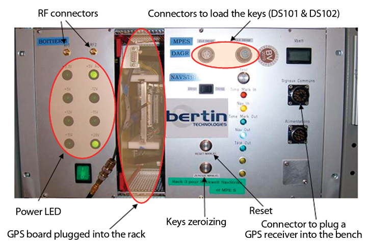
Figure 1. Depiction of SINERGHYS.Figure 2. Focus on the bench.
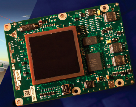
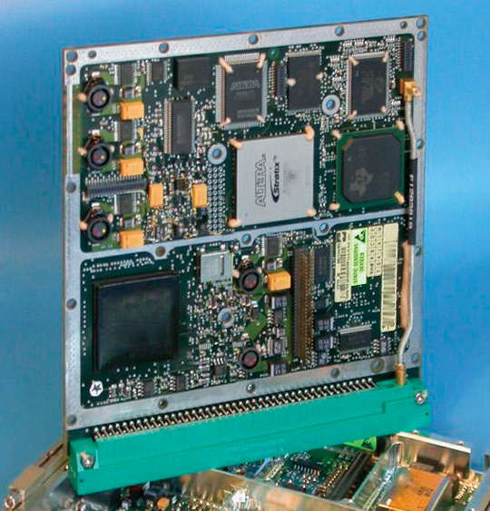
A Common Bench. Since 2000, with the arrival of the new cryptographic generation (the selective availability anti-spoofing module, or SAASM), the French government defence procurement agency (DGA) GPS laboratory decided to buy off-the-shelf GPS SAASM receivers that cover different form factors and applications. To test performance, it was necessary to acquire a test bench suitable for each GPS receiver. Testing procedures became more and more complex, and most of the manufacturer-provided benches could not perform every test required, such as direct P(Y) acquisition. To improve French expertise concerning GPS receivers, the DGA GPS laboratory decided to develop a common, generic test bench taking into account the integration constraints of each receiver. The perimeter of the hybrid test bench consists of a PC and a generic GPS test bench.
Figures 3 and 4 show examples of military GPS receivers integrated into the bench.
Figure 3. MPE-S (Ground-based application, Rockwell Collins).Figure 4. 1000S (Avionics,Thales).Figure 5. Embedded jammer.Figure 6. Jamming environment for a fighter aircraft. (Click to enlarge.)
Bench management is centralized, so test conditions are generic, and all simulation parameters are fully controlled. This enables users to display a unique view of the complete information and to be able to replay specific scenarios.
The bench manages military GPS receivers’ input and output data as described in the respective receivers’ interface control document (ICD) or interface specification: this enables, for example, the initialization of GPS receivers by sending precise time to facilitate direct P(Y) acquisition. This new bench is compatible with many GPS receivers with different form factors and applications.
Several receivers can be tested at the same time with the same software, so that the behavior of the GPS receivers can be compared in real time. Data from the different receivers can be observed on the same window of the graphic user interface (GUI). Specific data from ICDs can be displayed on the GUI. The user can visualize three different windows: the first is related to integrity, the second to alarms, and the third to cryptography. All the data output by the receivers can be recorded and replayed.
To facilitate and enhance trials on GPS receivers, the bench can use a Monte Carlo method, enabling sequentially and automatically chained scenarios, up to 10,000 test sequences, primarily for characterization of time-to-first-fix (TTFF).
Inertial navigation system (INS)/GPS hybridization in real time can be simulated via processing based on a Kalman filter of the information delivered by simulated INS and GPS. Loose and tight coupling can be selected through the GUI as well as filter parameters. The Kalman filter design is independent from the receiver and from the type of trajectory simulated. The user can decide whether the GPS receiver does receive aiding either from the simulated INS, or from the optimal navigation (output of Kalman filter).
Interfaces
The bench can interface with various external means and drive some tools and materials involved in the functioning of the bench.
With GPS Simulator. In the interface with the simulator, an intuitive GUI facilitates scenario preparation. When ready, SINERGHYS begins to drive the GPS simulator in remote-control mode. Any type of trajectory can be simulated with its operational environment modeled. The simulator outputs an RF signal to the receiver, and representative aiding, if required, by ethernet protocol to SINERGHYS.
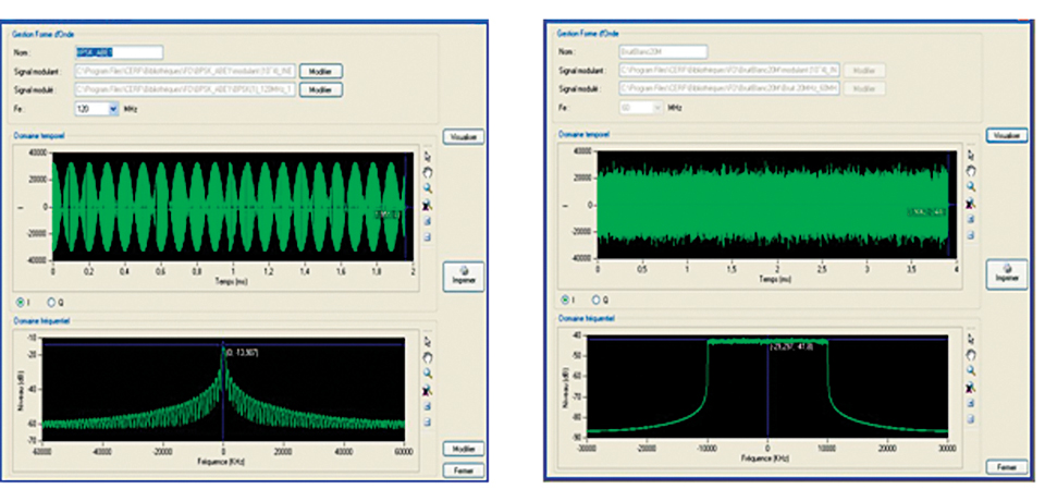
With Jammer. Two types of interference signal generators can be used with the bench. Any available waveform can be generated. The bandwidth can go up to 20 Mhz for one generator and up to 80 Mhz for the other.
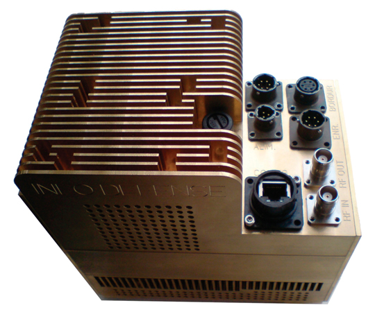
SINERGHYS is also compatible with a specific jammer called Embedded Jammer, designed to test vulnerability of GNSS systems (Figure 5).
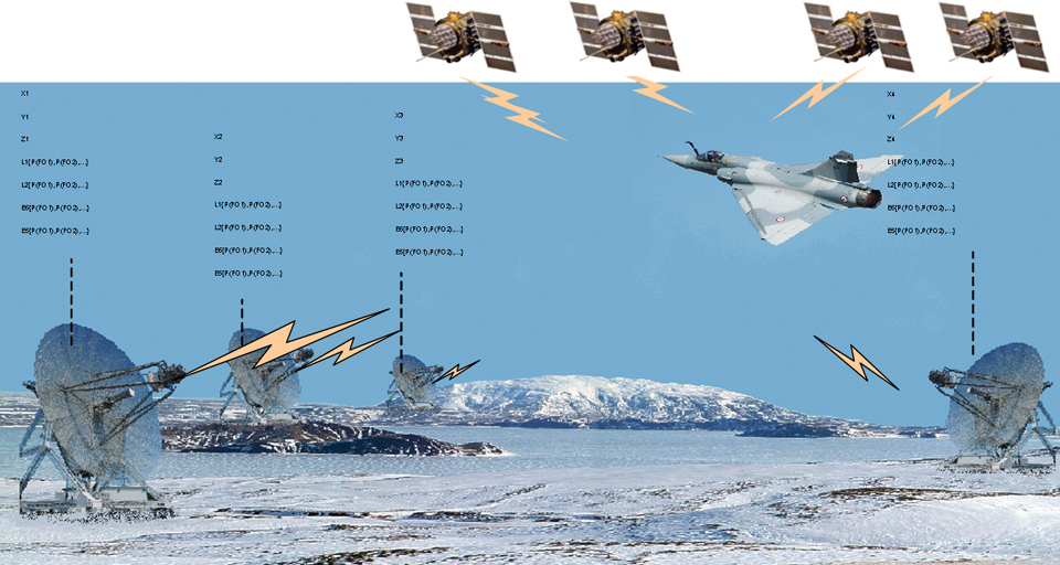
The GPS receiver under test tracks the real GPS satellites combined with the simulated jamming signal. Thanks to the position and attitudes provided by the aircraft and to a modelized antenna diagram, the jammer computes in real time representative jamming that would be generated by real jammers.
This jammer works in two modes: localized mode (coordinates, jammer power, and waveform) and power profile mode. It was initially designed to be used inside an aircraft but can be used for laboratory testing as well.
The simulated environment is defined in the configuration software: waveform, emitter, scenario definitions (bands, number of emitters), and antenna diagram.
Four GNSS bands can be selected: GPS L1 and L2 (40 MHz) and Galileo E6 (40 MHz) and E5 (90 MHz). The embedded jammer can generate up to 14 simultaneous jammers per band, each with different waveforms. Therefore, up to 56 simultaneous jammers can be simulated.
The center frequency of the jamming signals can be chosen anywhere in the bandwidth. Modulation examples: continuous wave, broadband noise, binary phase shift keying), binary offset carrier (x,y), and so on.
Figure 7. Modulation examples.
External software interfaces fall under three categories.
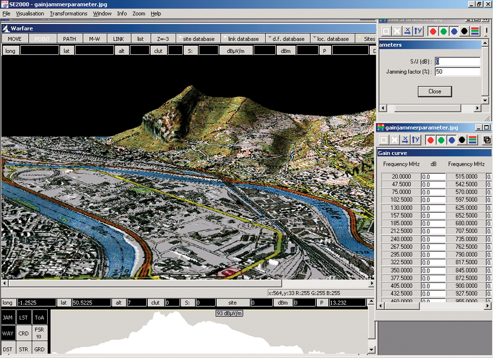
Warfare. Electronic warfare software, which provides jamming coverage, performs a precise assessment of propagation (reflection and diffraction) of the interfering signals (depending on terrain modeling). Interference levels are transmitted to SINERGHYS during pre-processing.
Figure 8. Warfare GUI.
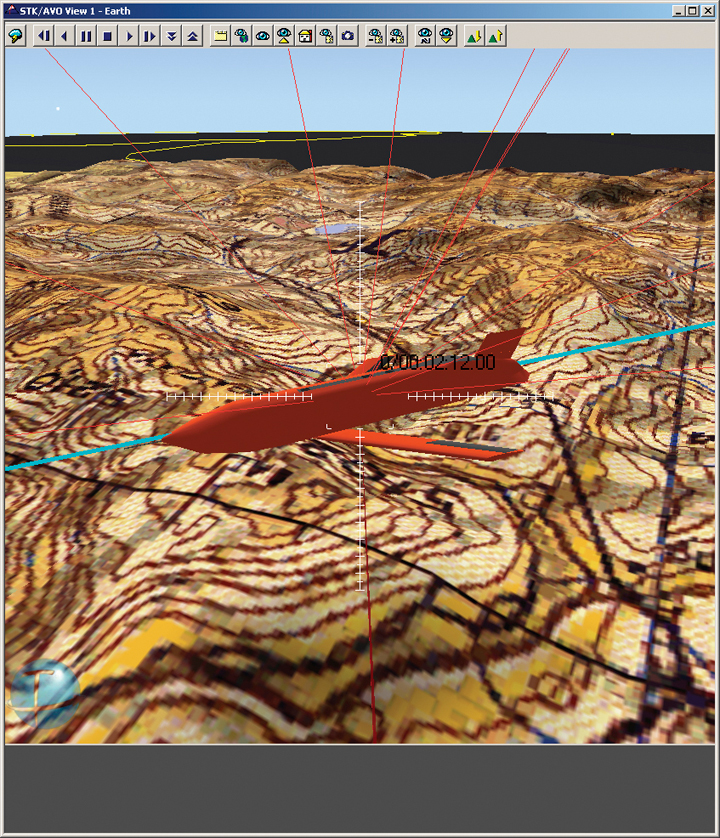
Satellite Tool Kit (STK). This software is designed to provide sophisticated modeling and visualization capabilities and performs functions critical to all mission types, including propagation of vehicles, and determination of visibility areas and times. STK generates paths for space and ground-based objects, such as satellites, ships, aircraft, and land vehicles. STK also provides animation capabilities and a two-dimensional map background for visualizing the path of these vehicles. Within SINERGHYS, STK is used for real-time visualization.
Figure 9. STK GUI.
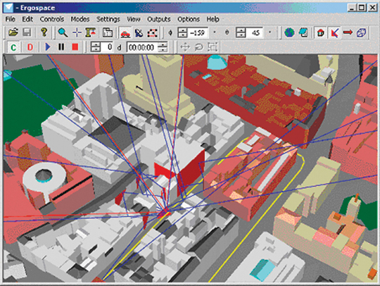
Ergospace. This software is designed to generate multipaths, enabling the modeling of reflected paths of different satellite signals on surfaces of realistic 3D scenes. Pre-processed multipaths are sent to SINERGHYS and generated by the GPS simulator. The software is also used for real-time visualization.
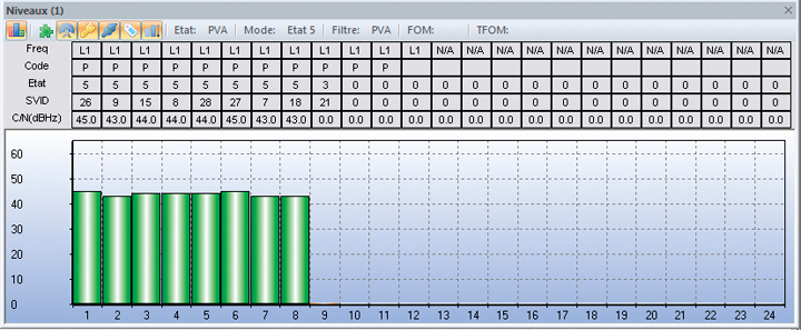
Figure 10. Ergospace GUI.Figure 11. Example of the window showing the general state of the GPS receiver (c/n, svid, gram receiver and channel states, code and frequency tracked).
Operational Mission Characterization
The bench can evaluate and characterize receiver performance in most possible representative conditions.
Management of GPS Inputs/Outputs. Both black and red keys can be loaded inside the GPS receivers in both DS101 and DS102 protocols. This loading can be performed manually through key loaders such as KYK13 or DTD/ANCYZ10, but also through the host application with hexadecimal keys.
The bench can send commands to GPS receivers such as non-volatile memory erasure command, INS, precise time source, precise time and time interval (PTTI) activation commands, or choices between “mixed mode” and “all Y,” between “L1 primary” and “L2 primary,” and so on. Depending on user requirements, the bench can provide time, position, speed, almanac, ephemeris, or specific navigation sub-frames.
To test the jamming resistance of GPS receivers, it is essential to be able to provide INS aiding. SINERGHYS uses perfect or degraded aiding and adapts the format or the frequency for the considered GPS receiver.
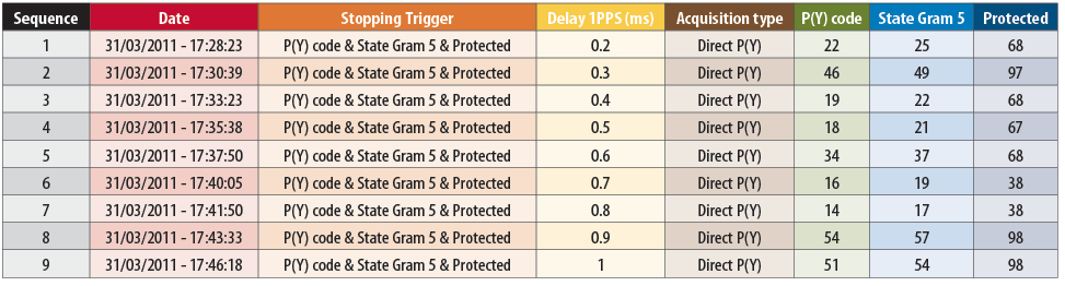
Direct P(Y) acquisition functionality is an important case that needs to be evaluated. The GPS receiver needs a precise time to perform direct P(Y) acquisition. The time accuracy, from a few nanoseconds to several milliseconds, has a strong impact on the GPS behavior. A special delay box applied to the pulse-per-second signal of the GPS simulator in accordance with PTTI message (that is, time figure of merit), enables such a simulated accuracy.
A standard IS 153-like interface was developed to display GPS data on a convenient GUI in order to have a common software to visualize output data from the GPS receivers. The user can also visualize some specific data from GPS ICDs concerning integrity, alarms, and cryptography.
All receiver output data are recorded for later analysis.
Table 1. Example of Direct P(Y) acquisitions in accordance with time uncertainty (with times to get “GRAM state 5” and “protected status”).
Monte Carlo Trials
The bench enables sequentially and automatically chaining scenarios (up to 10 000 test sequences) to perform statistics on acquisition times. Indeed, it is primarily used for the characterization of TTFF. GPS signal acquisition is dependent on many different parameters, as described in Figure 12. To properly characterize receiver acquisition times requires a large number of tests. The comparison with GPS Receiver Applications Module requirements can be easily performed.
Figure 12. Setup parameters to study GPS signal acquisition.Figure 13. Example of a random selection for the position error.
One Monte Carlo trial consists of a repetition of unitary test: powering the receiver, then sending to the GPS receiver random errors of position, speed, time, levels of jamming, and finally stopping the test sequence on trigger. At the end of Monte Carlo trials, statistical computing enables accurate analysis and expertises.
The random selections are optimized to reduce the number of cases. The bench can replay a particular case: as the seeds are deterministic, a special case of Monte Carlo method can be selected and replayed.
Real-Time INS/GPS Data Fusion
The information delivered by INS and GPS are processed by a Kalman filter. The INS trajectory is provided by the simulator or by an external file.
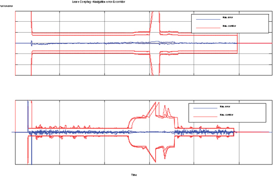
Two types of coupling are considered: loose coupling with position and velocity information, and tight coupling with pseudoranges and delta ranges to estimate errors. In both cases, the GPS receiver receives aiding from either the simulated INS or the optimal navigation (Kalman filter output).
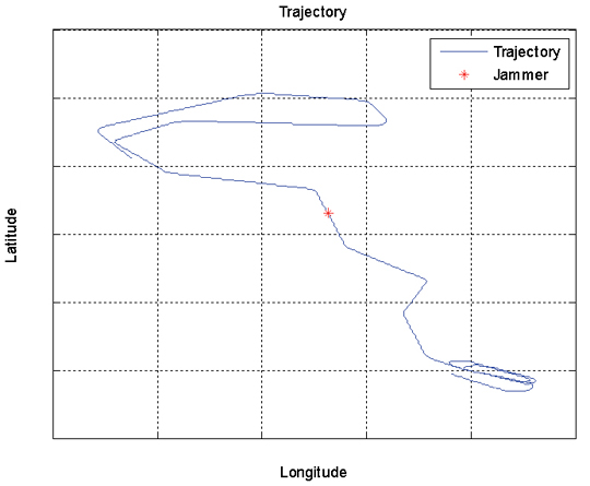
Figure 14. Example of an optimal navigation along a specified trajectory in a jamming environment.Figure 15. Position and velocity errors and navigation corridor.
The purpose of the Kalman filter is to estimate the navigation errors (position, velocity, and attitudes) and sensor errors (INS, GPS).
The filter design is original because it is independent from the receiver under test and from the type of application (hardiness privileged with reference to jamming). It is also able to estimate the time offset between position and velocity measurement on any GPS receiver under test.
Conclusion
SINERGHYS combines several resources into a single test bench. A complex mode can simulate an operational implementation with different interfaces and by chaining test sequences: receiver initialization, management of the switching of antenna patterns during a simulation, masking of GPS signals, management of jamming, INS/GPS data fusion, and so on. In this mode, missions can be replayed in a realistic environment. This bench is a complementary resource for flight trials and digital models because it can characterize the initialization phases with a good control of initial conditions. SINERGHYS enables users to know, as precisely as possible, the capabilities and limitations of a specific global navigation chain.
Manufacturers
SINERGHYS was developed by Bertin Technologies and specified by the French Ministry of Defense (MoD)DGA Information Superiority. It drives a Spirent GPS/Galileo simulator, Agilent 4431B and MXG generators, and software programs such as Analytical Graphics, Inc. (AGI) Satellite Tool Kit and Ergospace 3D scenes. The embedded jammer was developed by Ineo Defense in 2010 to MoD-DGA specifications.
Stéphane Gallot works at the French MoD (DGA Information Superiority) as a radionavigation expert. His particular interest is the integration of military GPS receivers including SAASM modules within French platforms.
Pascal Dutot is an architect engineer at the French MoD (DGA Information Superiority). His main activity is to optimize and control GPS integration in the global navigation chain.
Christophe Sajous works at the French MoD (DGA Information Superiority) as a radionavigation expert. He is also responsible for the “navigation per satellites” laboratory within the radionavigation department.
Corvallis Microtechnology, Inc. announces the release of the iGPSGIS II application software for use on the Apple iPhone. The GPS/GIS data collection and mapping application can be used in a range of applications such as resource management, agriculture, forestry, archaeology, and the utilities industry.
According to the announcement, in addition to displaying the GPS coordinates of geographic locations, iGPSGIS II provides user-friendly interface to facilitate the following tasks:
Create Feature Lists for data collection
Create sampling grids
Display Google Map as the background map
Import and Export Shapefiles
Collect multi-layer GPS/GIS data
Update the coordinates for Point Features
Create new points using angles and distances
Digitize points, lines and areas
Assign symbols and attributes to Features and Topics
View/Edit the collected data
View the area of an enclosed region
Measure distances on the displayed map
Send and receive job files via email
Store job data on the Cloud
Get and send job data via ftp
iGPSGIS II can be downloaded from the App Store by clicking here.
The IEEE/ION Positioning, Location and Navigation Symposium (PLANS) 2012 Executive Committee presented its Richard B. Kershner Award to Dr. Richard Greenspan at the IEEE/ION PLANS 2012 Conference on Thursday, April 26, in Myrtle Beach, South Carolina.
Greenspan was recognized for his pioneering work in the integration of GPS receivers with inertial navigation systems and the development and perfection of carrier-phase GPS interferometry for the high-precision measurement of fixed and moving baselines with applications to relative and differential ranging that cover the alphabet from agriculture to zoogeography.
Greenspan has been a member of the technical staff of The Charles Stark Draper Laboratory since 1978 where he has held both high-level management and technical positions. He currently holds the highest rank on Draper’s engineering ladder, where he is the technical lead on several initiatives to improve the situational awareness of our warfighters and reduce any “collateral damage” from their actions. These activities rely on the creative uses of unmanned aerial vehicles (UAVs) that exploit GNSS when they are available and other means when satnav is not fully available. U.S. warfighters are greatly benefiting from Greenspan’s sustained contributions to the art and science of satellite navigation that is highly integrated with other sensors, according to ION, the Institute of Navigation.
Greenspan has lectured worldwide on “Innovative Applications of Satellite Navigation” under sponsorship by the Advisory Group for Aerospace Research and Development of the North Atlantic Treaty Organization. He is a Fellow and a Past President of ION. He is also an Associate Fellow of the AIAA, a lifetime member of the IEEE, and a member of the AGU. He has been an associate editor of NAVIGATION: Journal of the Institute of Navigation since 1992 and has been consulting editor on navigation for McGraw-Hill’s Encyclopedia of Science and Technology since 1998. He holds several patents in the area of satellite navigation technology, has published many excellent and often referenced technical papers and was the invited author of the “GPS and Inertial Integration” chapter in the classic AIAA book Global Positioning System: Theory and Applications, Volume I.” He received his BS (1960), MS (1962) and Ph.D. (1968) in electrical engineering from MIT, all with high honors.
The Kershner Award is granted in recognition for substantial contribution to the technology of navigation and positioning equipment, systems or practices over their lifetime and is given in memory of Dr. Richard B. Kershner who participated in the initial conception and led the development of Transit, the world’s first navigation satellite system.
Trimble announced that it has entered into a definitive agreement to acquire SketchUp, one of the most popular 3D modeling tools in the world, from Google. The transaction is expected to close in the second quarter of 2012, subject to customary closing conditions and expiration of the waiting period under the Hart-Scott-Rodino Antitrust Improvements Act. While financial terms are not being disclosed the transaction is not expected to be material to 2012 earnings per share.
According to the announcement, as part of the SketchUp platform, Trimble will also partner with Google on running and further developing SketchUp’s 3D Warehouse, an online repository where users can find, share, store and collaborate on 3D models. The site enables users to create collections of models, including 3D Buildings, and share them with fellow modelers around the world. Individual models can be loaded, saved and viewed in 3D from within SketchUp or a web browser. For the foreseeable future, Google will host and operate the 3D Warehouse for Trimble and together the companies will continue to offer the same capabilities, functions and services that are offered today. The ability for users to submit 3D Buildings for potential acceptance and viewing in Google Earth will be maintained. Currently the 3D Warehouse has almost two million user-generated models.
“SketchUp and the corresponding 3D Warehouse provide an important element of our long term strategy by enhancing the integration of our field presence with the wider enterprise,” said Bryn Fosburgh, Trimble vice president. “Trimble has already created the de-facto standard for field data models and project management tools for our key markets. SketchUp, together with these existing capabilities, will provide a stand-alone and enterprise solution that will enable an integrated and seamless workflow to reduce rework and improve productivity for the customer. Users will be able to collect data, design, model, and collaborate on one platform. The combined capability will enhance our ability to extend our existing market applications including the cadastral, heavy civil, and building and construction industries. In addition, the SketchUp platform will enable Trimble, third-party developers and our distribution partners to efficiently develop new applications.”
“Since its inception, the SketchUp team has been committed to providing a robust, user-centric solution to its community and we look forward to engaging their talent and expertise. Beyond extending the reach of the product into Trimble’s commercial markets, we are committed to continuing to provide SketchUp as a free version to millions of users. Trimble and Google will also continue to collaborate on utilizing other Google tools for Trimble’s markets that, along with SketchUp, will provide our customers innovative and productive tools that transform their work,” concluded Fosburgh.
“In Trimble, we found a partner that will grow SketchUp in a way that best supports the SketchUp team and our users,” said Brian McClendon, Google’s vice president of engineering. “While at Google, the SketchUp community grew significantly because the team put users first, and we are confident they will continue to do so at Trimble. We at Google look forward to a continued partnership with Trimble and the SketchUp team.”
Trimble reports that SketchUp will continue to support all of its current users through its Web site at: http://sketchup.google.com. Concurrently, the SketchUp engine will be integrated into Trimble’s current solutions in its Engineering and Construction, Field Solutions and Mobile Solutions segments.