Author: GPS World Staff

  • Demands of the Road

    An Assisted-GNSS Solution Uses the EGNOS Data Access Service

    By Kevin Sheridan, Tomas Dyjas, Cyril Botteron, Jérôme Leclère, Fabrizio Dominici, and Gianluca Marucco

    For use in billing drivers in road-user charging schemes, onboard units employing GNSS must meet stringent reliability and availability requirements, and at the same time, be based on low-cost equipment systems. The SIGNATURE unit includes an assistance service which provides ephemeris data and corrections from EDAS, optimized for user location.

    As roads become more congested, governments and regional authorities seek better ways to manage their existing networks. Road-user charging (RUC) is increasingly promoted to tackle the congestion challenge: charging drivers a fee, perhaps on a monthly billing basis, derived from the distance their vehicles have traveled, time of travel, and whether congested roads were used.

    Recording trip information with a GNSS receiver in an onboard unit (OBU) provides a convenient and flexible means to support automated fee collection. For GNSS positioning to be used as the basis for billing drivers, however, it must meet stringent reliability and availability requirements, and at the same time be based on low-cost equipment.

    We have developed a prototype to provide both the positioning availability and integrity required for this application. The Simple GNSS Assisted and Trusted Receiver (SIGNATURE) includes an assistance service that provides ephemeris data and corrections from the European Geostationary Navigation Overlay Service (EGNOS) Data Access Service (EDAS), optimized for the user location. Assistance messages are sent to OBUs that can either host an experimental receiver or a commercial-off-the-shelf (COTS) receiver. Data from the receiver is processed with application-specific navigation algorithms on the OBU that aim to improve the integrity of the position solution relative to standard solutions.

    Field trials have assessed the contribution that assistance can make to positioning performance, and illustrate options for enhancing standard assistance solutions. Enhancements to assistance encompass modifications to the message content and alternative means of communications, showing the benefits and feasibility of a broadcast service. The impact of including EGNOS corrections through a broadcast assistance service in urban areas is also under investigation.

    GNSS Road-User Charging

    RUC has the potential to reduce congestion, lower vehicle emissions, and generate revenue streams for infrastructure improvement. It can ensure that revenues are based on actual road usage, creating a financial incentive for changing driving behavior. This might include lower overall use of private cars and, in particular, reducing peak-time travel levels in urban areas by effectively spreading out the morning and evening rush hour. RUC can also encourage commuters to use alternative forms of public transport.

    To automate the process of collecting charges, electronic fee-collection (EFC) systems have been developed based largely on dedicated short-range communications (DSRC). In a DSRC solution, a simple tag on the vehicle receives a signal when it passes a roadside beacon and a charge is computed accordingly. Cameras with automatic number-plate recognition (ANPR) technology are also widely used, mainly as an enforcement tool.

    Both technologies rely on fixed roadside infrastructure. As charging schemes to date have focused on specific areas (individual cities) or road infrastructure (major motorways, tunnels, and bridges) this type of technology provides an adequate solution.

    To meet future policy goals, however, this is not feasible. More extensive charging schemes covering greater areas, more road types, more classes of vehicle, and which will vary charges depending on location and time of day require a far more flexible solution. Flexible schemes require the positioning element to be onboard the vehicle. GNSS-based devices, possibly augmented with other sensors, have been identified as the best option to achieve this.

    Using GNSS, the OBU tracks the location of the vehicle, and this is matched against the road network to calculate a charge. A GNSS solution can support many different charging strategies including time distance and place (TDP) based charging for road sections, geographic areas, and cordon schemes. While GNSS offers great potential, several operational and performance limitations have prevented more widespread adoption. Operationally, OBUs are relatively expensive, fraud prevention is potentially complex, and charging schemes must also accommodate infrequent users. GNSS performance is limited in terms of the ability to provide sufficiently accurate positions with high availability and integrity in all operating conditions.

    To be fully flexible and to target congested areas, OBUs must work in all environments including urban areas. Urban-canyon problems, with satellite signals blocked and reflected, are well documented. In some cases, not enough signals are available to determine a position, and when there are enough satellites, the ranges will be prone to errors and the geometry is likely to be poor. Signals are more likely to be available in the longitudinal direction of the street, but with few or no satellites on either side of the vehicle. Signal blockage is a particular problem when the GNSS receiver is started up, and it attempts to decode satellite ephemeris data. This requires around 30 seconds of uninterrupted tracking with a relatively strong signal for each satellite, and in an obstructed urban environment it may take many minutes to determine the first receiver position.

    Charging schemes typically aim to charge for at least 99 percent of road usage. If a typical journey length is 30 minutes, this means that only 18 seconds with no usable position solution can be tolerated and hence time to first fix (TTFF) must be below 18 seconds, and ideally much lower.

    When positions can be determined, they must be sufficiently accurate to identify the correct road segment that the vehicle was on, and they must be reliable. Reliability, or integrity, becomes critical if road users are to be charged on the basis of GNSS-derived positions. Users must have confidence that they are being charged correctly for schemes to be effective and to gain public acceptance.

    Whilst GNSS-based solutions are entering the market, for example in Germany and Slovakia for heavy goods vehicles, barriers to wider adoption remain. Many countries are considering GNSS-based road pricing, and they all face similar challenges in ensuring the accuracy, integrity, and availability of a GNSS-based solution for nationwide deployment.

    SIGNATURE Solution

    The principal objective of the SIGNATURE project is to prototype a GNSS-based solution for flexible road-user charging that can provide the required high integrity and high availability in a cost-effective and scalable manner.

    This robust, high-availability, high-integrity solution is delivered firstly through providing reliable assistance (A-GNSS) data from EDAS to optimize receiver acquisition and tracking capabilities and reduce TTFF, and secondly through implementation of embedded GNSS reliability algorithms into an OBU, providing assurance of positioning information (Figure 1, at top).

    These features are intended to make a positive contribution in terms of the key RUC performance criteria, as defined by the GNSS Metering Association for Road User Charging:

    • Accuracy: right cost per trip
    • Integrity: probability and amount of overcharging
    • Availability: amount of charged usage.

    Assistance Server. An assistance service supplying suitably equipped OBUs is one means to maintain rapid TTFF and meet the requirement for high positioning availability. The most significant contribution assistance can make to TTFF is to provide the
    ephemeris data, which takes around 30 seconds to download from a satellite signal. Assistance data can also reduce the frequency search space when a receiver is acquiring signals, as the expected Doppler frequency can be computed from the approximate receiver and satellite positions.

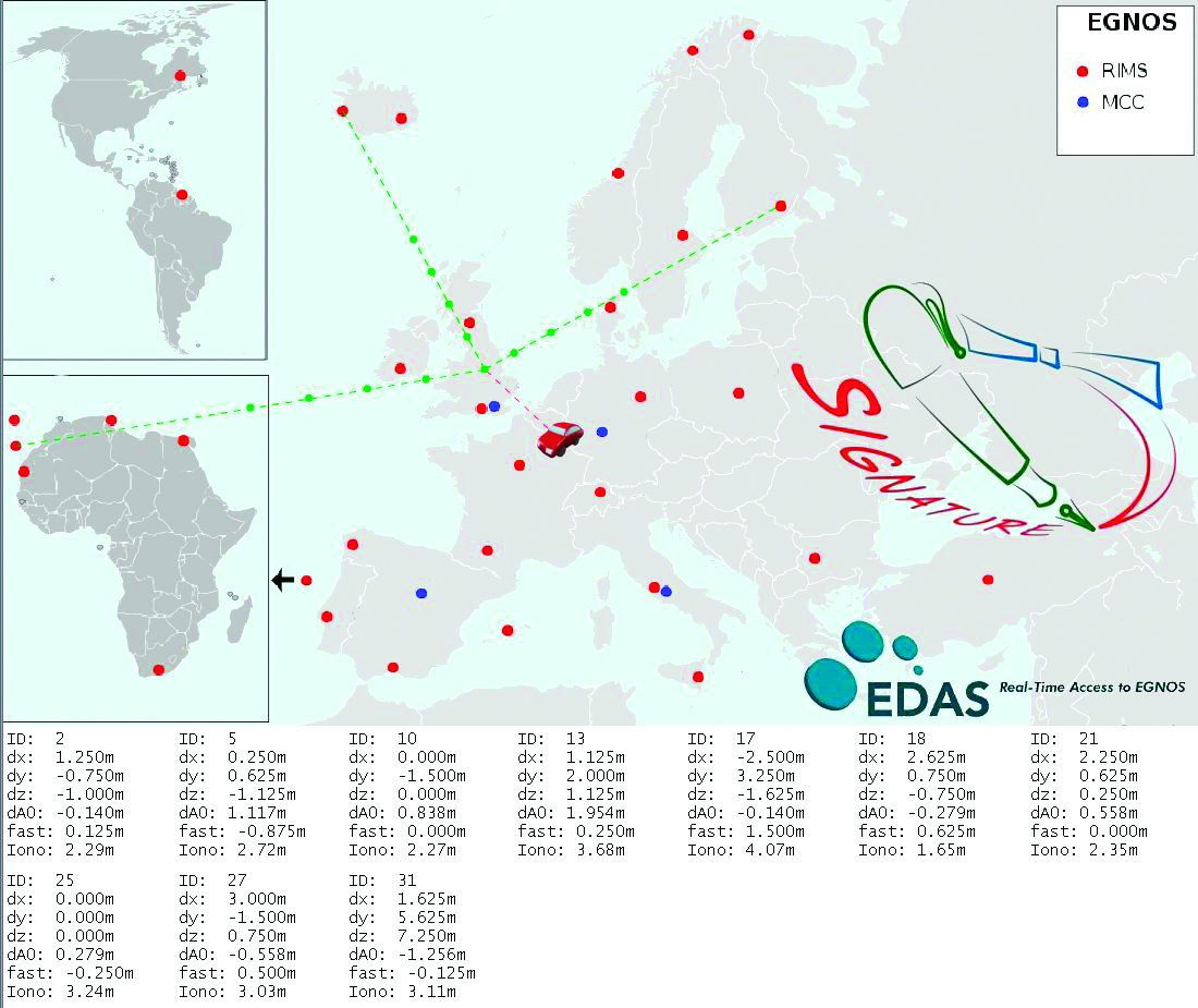
    The assistance server in SIGNATURE is based on EDAS, currently available as a beta version. EDAS allows a user to plug into EGNOS to receive the data collected by all the current EGNOS Ranging and Integrity Monitoring Stations (RIMS). This makes it possible to access EGNOS data when there is no clear sight to the EGNOS geostationary satellites, which can often be the case in urban areas, particularly at higher latitudes. As well as supplying EGNOS messages, EDAS also provides GPS observation and navigation (broadcast ephemeris) data, the key component as far as an assistance service is concerned. By recording the ephemeris data received at the extremities of the monitoring network, it is possible to ensure that the current ephemeris for any GPS satellite in view to users over Europe is available and can be supplied in an assistance message. Other data streams provided by EDAS can also be used to enhance the assistance solution.

    The main enhancement tested in SIGNATURE was the use of EGNOS corrections within the assistance message. EGNOS today consists of a space segment of three geostationary satellites broadcasting correction and integrity information in the L1 band. Three sets of corrections are broadcast to users:

    • Fast corrections: used to compensate short-term disturbances in GPS signals, generally attributable to satellite clocks;
    • Long-term corrections: used to compensate for the longer-term drift in satellite clocks and the errors in the broadcast satellite orbits
    • Ionospheric corrections: broadcast as a grid of vertical delays (GIVD) from which a user receiver can determine a slant correction to be applied on each range measurement to compensate for the delay experienced by the signal as it passes through the ionosphere.

    Fast and long-term corrections are added to the ephemeris data in the assistance message. Rather than relaying the GIVD data to the OBU and letting the receiver reconstruct the ionospheric grid and calculate slant corrections, this is done within the assistance server. A slant correction is provided for each satellite that will be in view at the user location. This approach is valid provided the OBU updates the corrections regularly enough to take account of the changing satellite elevations and ionospheric conditions. It provides a significant saving in terms of processing and memory consumption at the OBU, while still delivering the accuracy benefit of the EGNOS ionospheric data. To correct for the tropospheric delay, a zenith value (ZTD) determined from the RTCA model is also included in the assistance message. Mapping this zenith value to a slant correction to be applied to satellite ranges is a straightforward process easily accommodated on the OBU.

    Figure 2 shows how data from EGNOS RIMS is collected at the assistance server at NSL in Nottingham, UK, and then used to generate messages. In this case, the assistance data was provided for trials conducted in Brussels. The figures at the bottom of the plot are the EGNOS correction values provided for all 10 GPS satellite in the positioning solution.

    Source: Kevin Sheridan, Tomas Dyjas, Cyril Botteron, Jérôme Leclère, Fabrizio Dominici, and Gianluca Marucco
    Figure 2. Schematic of assistance solution.

    Further enhancements are also possible using the GPS observation data provided through EDAS. Firstly, for areas close to RIMS, a local differential solution can be applied using standard DGPS techniques to provide pseudorange corrections rather than wide-area EGNOS corrections. This has the potential to give greater accuracy for certain areas and is under investigation. By combining EDAS data sources, a GNSS performance monitoring and prediction service has also been created (Figure 3). This provides an assessment of GPS and GPS+EGNOS positioning performance (accuracy, availability of corrections, integrity) at known reference stations as well as monitoring the availability of EDAS data from its central server. Monitoring of this kind can be used as a further tool to identify system-level problems that might significantly degrade user positioning solution, perhaps to a level at which charges could not confidently be applied. It can also aid the enforcement process, as a diagnostic tool to identify if missing or misleading data from an OBU could be due to a system-wide fault or to a more localized source.

    Source: Kevin Sheridan, Tomas Dyjas, Cyril Botteron, Jérôme Leclère, Fabrizio Dominici, and Gianluca Marucco
    Figure 3. GNSS performance monitoring using EDAS.

    This approach relies on the approximate user position being known at the assistance server. To maintain the validity of the corrections, it would also require a receiver to update its assistance data at a much high rate than would usually be the case. For a large-scale operation this would be unfeasibly expensive using cellular communications (GSM/GPRS), however it would be possible using a broadcast assistance approach. Using a radio data service (RDS) broadcast for example, ephemeris data and EGNOS corrections could be provided on a continuous basis. RDS is an auxiliary signal to the FM radio broadcast system and is used routinely for supplying travel information to in-car navigation systems. As data is broadcast from known locations and over a definable coverage area, messages can be generated that are applicable for all users receiving data from a given transmitter. A drawback of RDS is that it has a relatively low bandwidth, and it takes approximately 3.5 seconds to broadcast an ephemeris message for a single satellite. A further argument against RDS as a long-term solution is that analog radio signals are progressively being phased out in favour of digital alternatives. With the far greater bandwidth of digital audio bßroadcasting (DAB), ephemeris data for 12 satellites could be broadcast in less than 1 second.

    We are evaluating alternative message content and transmission options to determine if real benefits can be gained by providing additional content, other than the ephemerides, in the assistance message.

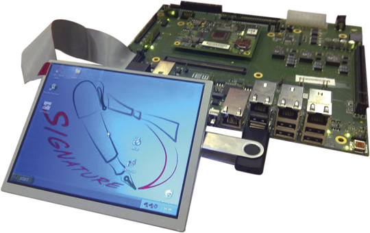
    Onboard Unit. The SIGNATURE OBU (Figure 4) is based on a single-board computer (SBC) offering a high degree of flexibility. Developed by ISMB, it can host alternative receivers and positioning algorithms and manipulate different assistance data with a high degree of configurability. It is a powerful platform for developing and assessing OBU devices and their component parts, particularly as it allows lots of useful diagnostic data to be logged.

    Source: Kevin Sheridan, Tomas Dyjas, Cyril Botteron, Jérôme Leclère, Fabrizio Dominici, and Gianluca Marucco
    Figure 4. SIGNATURE Prototype Onboard Unit (OBU).

    The OBU hosts a bespoke receiver which exploits the continuous availability of assistance data available through a high-speed data packet access connection and does not attempt to decode navigation data directly from satellite signals. This allows its design to focus on rapid signal acquisition with high sensitivity and to achieve a rapid TTFF even in areas where conventional receivers struggle. The SIGNATURE prototype has been designed using the well known SAT-SURF & SAT-SURFER platform.

    The receiver, developed by the EPFL, implements massive parallelization by making use of the fast Fourier transform, leading to a processing power equivalent to approximately 650,000 equivalent correlators. The minimum sensitivity in acquisition is –145 dBm, obtained using coherent and non-coherent integrations. Thanks to the massive parallelization and the assistance, TTFF at –145 dBm is still below 3 seconds.

    Positioning Algorithms. The OBU hosts positioning algorithms designed by NSL to provide high accuracy, availability, an
    d integrity through exclusion of outlying measurements and provision of quality metrics (horizontal protection levels or HPLs). Numerous positioning algorithms and outlier detection strategies are being investigated. These include consistency checks applied to raw measurements and computed positions and receiver autonomous integrity monitoring (RAIM). EGNOS corrections are applied to improve accuracy and integrity indicators (user differential range error indices) are used as coarse fault-detection barrier. Consistency checks on measurements include differencing pseudoranges between epochs and checking that this rate is below a defined threshold. A RAIM algorithm is then applied to detect and exclude outliers before measurements enter the main navigation filter. Positions and velocities determined by the filter are then checked again as a further fault barrier. Checks at this stage identify if speeds are within expected ranges for the application and whether height changes are reasonable, for example.

    The RAIM algorithm is based on the maximum normed residual method. For the detection procedure, the test statistic is calculated based on weighted sum of the squares of the residuals. This test statistic undergoes a globaltest (chi-square distribution), and is tested against thresholds that are computed based on the probability of false alarm (Pfa) and degrees of freedom (number of measurements minus number of unknowns). The exclusion procedure is based on an outlier detection technique also known as data-snooping, which is based on normed residuals and applied within the range domain. This technique uses measures of internal and external reliability, where the internal reliability gives estimates of how reliable the outlier detection procedure is, while the external reliability gives estimations of the influence of an outlier.

    In the final step of the exclusion procedure, the maximum normed residual is tested against a critical value based on the normal inverse cumulative distribution, which in turn depends on the Pfa, and a decision is made on whether or not to exclude measurements. Having performed fault detection and fault exclusion until no further outliers are found, an HPL is calculated. This is the maximum horizontal position error that is guaranteed by the algorithm not to be exceeded, in accordance with the required probabilities of missed detection and false alarm. HPL is a function of visible satellites, expected error characteristics, and user geometry. Measurements which have been screened using the RAIM fault detection and exclusion are then processed in a Kalman filter.

    Within the project, many alternative algorithms and configurations are being tested. As well as using RAIM in a snapshot mode to screen measurements entering the Kalman filter, fault detection can also take place within the innovation sequence of the filter itself. Weighting strategies that consider signal-to-noise ratios (SNR) as well as satellite elevations are also being used. This combined weighting is useful in reducing the impact of measurements affected by multipath in urban areas where simple elevation dependent models are often not applicable. The ultimate aim is to produce a robust GNSS positioning solution optimized for RUC in urban areas that balances the requirements of providing high availability with high integrity.

    Test Methodology

    The SIGNATURE end-to-end solution was tested in a series of field trials in the UK and Italy between April and July 2010. Trials took place in a range of operating conditions from rural areas with open skies to dense urban environments. In all trials, assistance data was provided from the service center in Nottingham, with messages tailored for the designated test area. The OBU recorded real-time position solutions as well as logging all raw measurements. Journey records can be sent back to the service center over a GPRS connection or can be downloaded back at the office. This allowed alternative solutions to be applied to the original datasets in post processing.

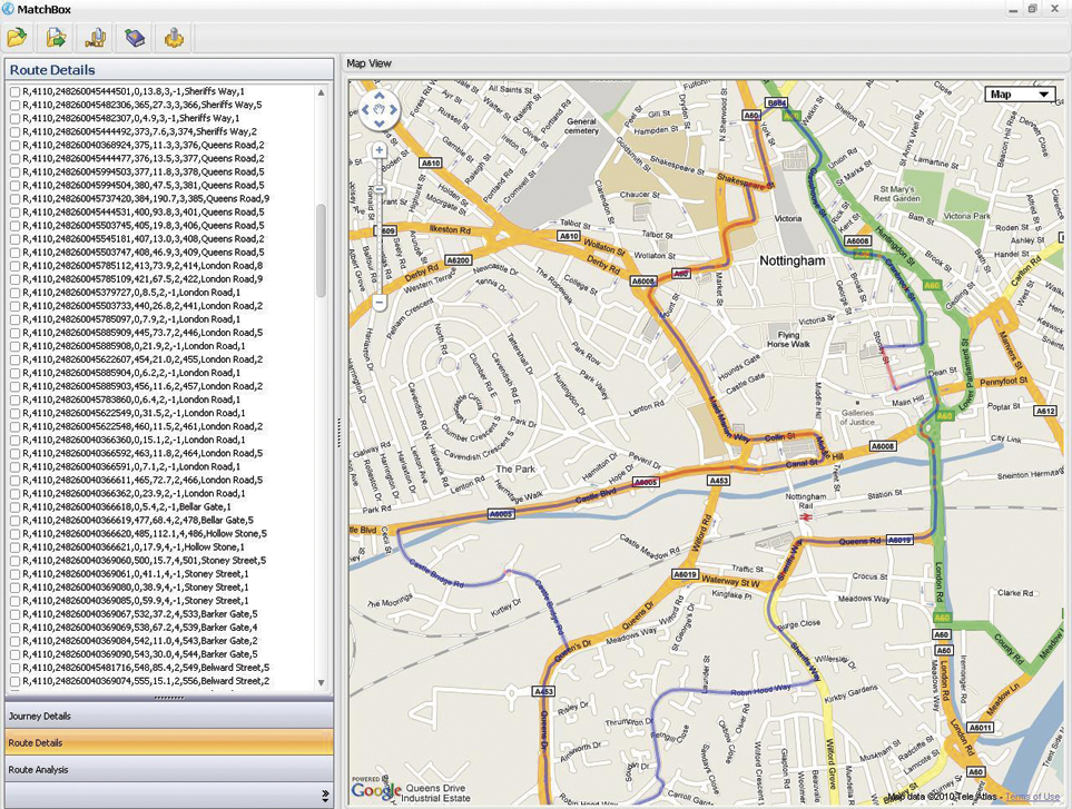
    The position solutions were assessed through comparisons with high-accuracy GNSS reference solutions provided by additional onboard equipment and through processing with a map matcher (NSL’s Matchbox). Each journey record from a trial was compared against the known reference journey record to determine charging availability, accuracy, and integrity.

    Using this approach, it is possible to assess whether improvements in the OBU position output are significant in terms of matching the vehicle location correctly to more road segments and with higher confidence. From direct comparisons between OBU positions and a high-accuracy reference solution alone, it is not possible to determine the significance of any changes in the OBU output in terms of final charging performance. Extensive trials of GNSS OBUs in London, for example, did not observe a relationship between location error (from OBUs) and performance at road segment level (map-matching) as map-matching can compensate for many errors. A strong relationship was observed between data availability and performance, though. Ultimately it is important to consider how successfully vehicle position can be related to charging objects, be they road segments, cordons or virtual toll-gates.

    The objectives of the field tests were to:

    • Demonstrate that all elements of the end-to-end solution work as expected.
    • Assess the impact of assistance on TTFF.
    • Evaluate benefits of EGNOS data.
    • Investigate alternative positioning algorithms to optimize availability and integrity.
    • Demonstrate the feasibility of broadcast assistance using RDS.

    Results

    Field trials around Nottingham and Torino tested all elements of the solution. The tests confirmed the successful generation, transmission and use of assistance data, including EGNOS corrections. Position solutions determined onboard were transferred back to the service centre and processed with a map matcher. Figure 5 shows an example from a test in Nottingham city center, correctly identifying all the road segments travelled on.

    Source: Kevin Sheridan, Tomas Dyjas, Cyril Botteron, Jérôme Leclère, Fabrizio Dominici, and Gianluca Marucco
    Figure 5.Journey record view from Nottingham test. (Click to enlarge.)

    Assess Impact of Assistance on TTFF. To examine the benefits of assistance, a series of trials were conducted to compare the TTFF of a consumer-grade receiver typically used in road applications against the performance of the SIGNATURE receiver that is assisted in all cases. They assessed TTFF for the COTS receiver in the following modes:

    • Hot Start: receiver has up-to-date almanac and ephemeris information so only needs to obtain timing/ranging information from each satellite to return its position fix;
    • Warm Start: receiver has the almanac information stored in its memory, but it does not have any ephemeris information. It also has approximate time and position knowledge. It can use this information to search for satellites but will then need to demodulate the ephemeris data from acquired signals;
    • Assisted: ephemeris provided over OMA-SUPL standard channel.

    Table 1 shows the results from testing the receivers in open sky and urban conditions, specifically chosen to assess an extreme acquisition environment. In these tests when no valid ephemeris is available on a receiver at start-up, it takes an average of 28 seconds to determine a first position fix in open sky conditions. This increase to an average of more than 2 minutes in the worst-case urban environment as the receiver struggles to decode the navigation message on weak, noisy, and intermittent signals. With assistance, the SIGNATURE receiver maintains a rapid TTFF, outperforming the COTS receiver. The slower TTFF in the assisted COTS case may be partly due to the OMA-SUPL standard procedure
    which is based on a more complex than the simple data transfer used in the SIGNATURE procedure. The COTS receiver is also decoding navigation subframes to determine signal transmission time. This can take up to 6 seconds depending on the point in the transmission cycle that acquisition begins.

    Tests have also been carried out using a signal generator to control the strength of the received signal to assess acquisition and tracking sensitivity. At –145 dBm, the SIGNATURE receiver takes an average of 1.1 seconds to acquire 4 satellites and determine a first fix, and 5.1 seconds to acquire 12 satellites.

    Positioning Algorithms. A variety of configurations have been investigated in the positioning algorithms, including applying outlier-detection routines at different stages of the solution and comparing snapshot and filtered approaches. Figure 6 shows a simple example of how the RAIM algorithm has been effective in detecting and excluding outlying measurements contaminated by multipath. By removing these meaurements and re-computing the OBU location, better position estimates are obtained.

    Source: Kevin Sheridan, Tomas Dyjas, Cyril Botteron, Jérôme Leclère, Fabrizio Dominici, and Gianluca Marucco
    Figure 6. RAIM Impact (red = no RAIM, yellow = RAIM).

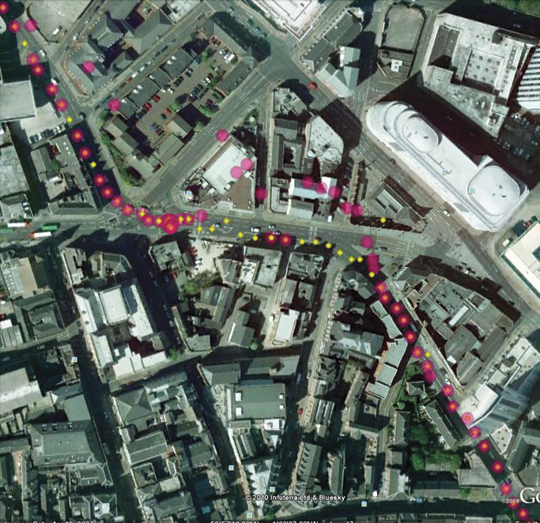
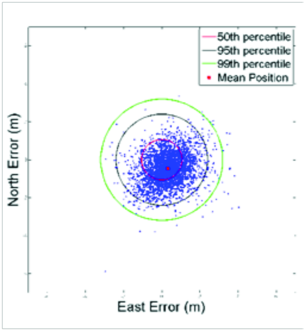
    Figure 7 shows the accuracy and integrity of the SIGNATURE solution assessed using a high-grade GNSS/INS reference in Nottingham city center. In this case, the horizontal accuracy is 4.4 meters (95 percent), and the computed protection level is shown to bound the actual position error with the required confidence.

    Source: Kevin Sheridan, Tomas Dyjas, Cyril Botteron, Jérôme Leclère, Fabrizio Dominici, and Gianluca Marucco
    Figure 7. Position error and protection level, Nottingham city center.

    In rural, semi-urban, and urban (Nottingham) conditions, a positioning solution has been demonstrated that supports all charging accuracy, integrity, and availability requirements.

    Further tests were also conducted in the center of London, in a worst-case obstruction environment. In this area the current solution falls just short of the requirements defined for this project. In such cases, better performance could be obtained using a hybrid solution making use of additional sensor inputs, but this will increase equipment costs and potentially installation costs, too. A more practical approach may be to simplify charging schemes in the densest urban environments, using zones and cordons rather than using more detailed approaches that require a continuous high-performance positioning solution to be maintained in all conditions.

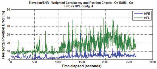
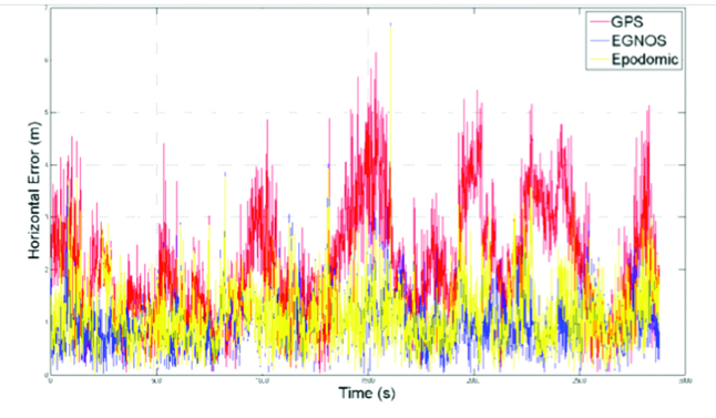
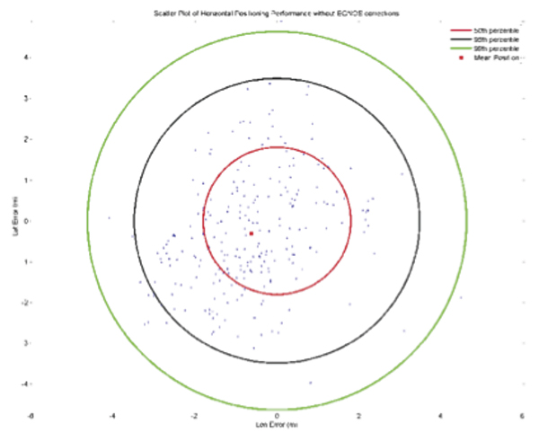
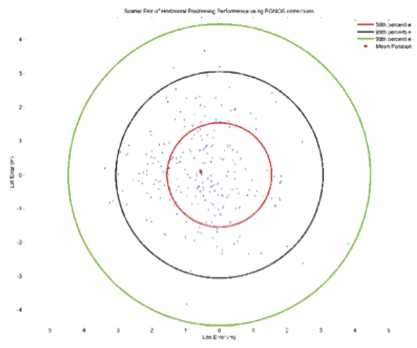
    Benefits of EGNOS Data. The SIGNATURE solution has the ability to provide EGNOS data to positioning algorithms on the OBU and to vary the rate at which this information is updated and used. Field tests have assessed the potential benefits of this source of data in various environments, starting from the case in which EGNOS messages are continuously available for the positioning solution and then investigating how any beneficial effects lessen as the data is provided less frequently. The greatest benefit from EGNOS was derived by applying corrections prior to performing the RAIM FDE algorithm. This led to more consistent measurements and produced lower HPL values. Figure 8 shows a comparison for a Nottingham test in which a GPS-only solution is compared against an EGNOS solution in which a full set of corrections is provided.

    Figure 8. HPL GPS vs GPS + EGNOS.
    Figure 8. HPL GPS vs GPS + EGNOS.

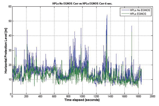
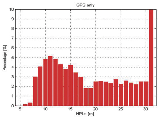
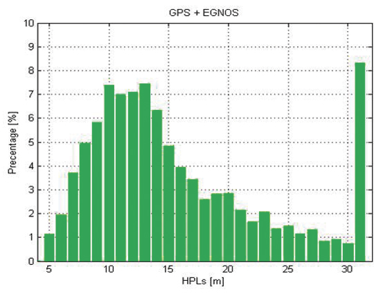
    This reduction in HPL values through the application of EGNOS corrections is clearer when the distribution of HPL values falling into discrete bins is assessed (Figures 9 and 10). Similar levels of relative improvement have been found through using this approach in all test datasets. The significance of these improvements can only be judged against the detailed specifications of a particular charging scheme.

    Source: Kevin Sheridan, Tomas Dyjas, Cyril Botteron, Jérôme Leclère, Fabrizio Dominici, and Gianluca Marucco
    Figure 9. HPL distribution GPS.
    Source: Kevin Sheridan, Tomas Dyjas, Cyril Botteron, Jérôme Leclère, Fabrizio Dominici, and Gianluca Marucco
    Figure 10. HPL distribution GPS + EGNOS.

    Conclusions

    Using an assistance service based on EDAS, it is possible to achieve a TTFF of a few seconds, which supports the high availability requirements of RUC. Field trials showed that providing EGNOS information over the assistance data link had an integrity benefit. Applying corrections prior to a RAIM algorithm leads to more consistent measurements and reduces HPLs. Robust positioning solutions have been developed and implemented on the OBU, and a test methodology has been put in place to assess the impact on charging availability, accuracy, and integrity. Results indicate that GNSS-based road charging offers the performance and flexibility to meet current and future requirements, provided availability and integrity issues are properly taken into account.

    Acknowledgments

    The SIGNATURE project has received funding from the European Community’s Framework Programme (FP7/2007-2013) under Grant Agreement No. 228237 and is supervised the European GNSS Supervisory Authority (GSA). Full details of the project can be found at www.gnsssignature.org. Any views expressed here are entirely those of the authors and do not necessarily represent the EC.

    Manufacturers

    The SIGNATURE receiver is based on the Terasic Altera DE3 System with a high-density Stratix III FPGA (EP3S260), and on the Rakon GRM8652 high-performance front end.


    Kevin Sheridan is technical manager at Nottingham Scientific Limited (NSL),where he works on development of robust GNSS positioning solutions for urban applications. He has a Ph.D. from University College London.

    Tomas Dyjas is a navigation engineer at NSL where he develops and tests positioning algorithms for an experimental OBU for road-user-charging (RUC) and evaluating novel integrity approaches for aviation.

    Cyril Botteron manages research and project activities of the GNSS and UWB research subgroups at the Ecole Polytechnique Fédérale of Lausanne (EPFL) in Switzerland. He received a Ph.D. from the University of Calgary.

    Jérôme Leclère is a Ph.D. student at EPFL. His research focus is on acquisition and high-sensitivity GNSS receivers.

    Fabrizio Dominici is the head of technologies for Galileo/EGNOS applications and embedded systems at Istituto Superiore Mario Boella (ISMB). He received a master’s degree in communications engineering from Politecnico di Torino.

    Gianluca Marucco received a master’s degree in electronics engineering from Politecnico di Torino. His research interests include multipath mitigation techniques for future Galileo receivers and real-time performance monitoring services for EGNOS.

  • The System: Test Data Predicts Disastrous GPS Jamming by FCC-Authorized Broadcaster

    Representatives of the GPS industry presented to members of the Federal Communications Commission (FCC) laboratory evidence of interference with the GPS signal by a proposed new broadcaster on January 19 of this year. The meeting and subsequent filing did not dissuade FCC International Bureau Chief Mindel De La Torre from authorizing Lightquared to proceed with ancillary terrestrial component operations, installing up to 40,000 high-power transmitters close to the GPS frequency, across the United States.

    The document describing the testing states that the Lightsquared initiative “will have a severe impact on the GPS band” and “will create a disastrous interference problem for GPS receiver operation to the point where GPS receivers will cease to operate (complete loss of fix) when in the vicinity of these transmitters.”

    On January 26, the FCC waived its own rules and granted permission for the potential interferer to broadcast in the L Band 1 (1525 MHz–1559 MHz) from powerful land-based transmitters. This band lies adjacent to the band (1559–1610 MHz) where GPS and other GNSSs operate.

    The FCC called for further testing to be led by LightSquared and completed by June 15.

    Prior to the decision, representatives of the U.S. GPS Industry Council and GPS manufacturers Garmin and Trimble presented “Experimental Evidence of Wide Area GPS Jamming That Will Result from LightSquared’s Proposal to Convert Portions of L Band 1 to High Power Terrestrial Broadband,” to five members of the FCC’s Office of Engineering and Technology, including its chief, two members of the FCC International Bureau, one from the Public Safety and Homeland Security Bureau, and two from the Wireless Telecommunications Bureau.

    A full PDF of “Experimental Evidence of Wide Area GPS Jamming” is available.

    The document conveys results of testing on a common portable consumer automotive navigation device and on a common general aviation receiver. The consumer GPS device began to be jammed at a power level representing a distance of 3.6 miles (5.8 kilometers) from the simulated LightSquared transmitter. The consumer device lost a fix at 0.66 miles (1.1 kilometers) from the transmitter.

    The Federal Aviation Administration (FAA)-certified aviation receiver began to be jammed at a distance of 13.8 miles (22.1 kilometers) and experienced total loss of fix at 5.6 miles (9.0 kilometers) from the transmitter.

    During the laboratory testing, GPS signals were simulated by a Spirent GSS6560 GPS simulator, representing a constellation of 31 GPS satellites, the current configuration. LightSquared’s signal was simulated using a Rhode and Schwartz SMIQ-03S signal generator with digital modulation, amplified to achieve the relevant signal strengths. Full technical specifications and parameters are described in the Experimental Evidence document linked above.

    The industry report concludes: “The proposed LightSquared plan . . .  will deny GPS service over vast areas of the United States.”
    In its decision document on January 26, the FCC not only authorized LightSquared to proceed, it turned up its nose at assertions that the entire process had been conducted in near-stealth mode as well as on an accelerated track.

    LightSquared was established in mid-2010 by “an experienced team of global telecommunications executives and investors.” From 2001 to 2005, Lightsquared executive vice president Jeff Carlisle served as deputy chief and then chief of the FCC’s Wireline Competition Bureau.

    See also “Act Now to Protect GPS Signal.”

    and

    “The FCC’s Decision on LightSquared: High-Precision Users Would Be Affected Most.”

    Galileo’s GATE Opened

    The Galileo Test and Development Environment (GATE) in Berchtesgaden, Germany, officially opened on February 4. The system operator, IFEN GmbH of Poing, Germany, jointly with the German Federal Minister of Transport, Building and Urban Development, announced the opening for use by commercial and organizational entities seeking to test equipment with the coming Galileo signals. GATE was developed on behalf of the German Aerospace Center (DLR) with funding by the German Federal Ministry of Economics and Technology.

    The test area extends across a valley of approximately 65 square kilometers, southeast of Munich, where antennae atop surrounding peaks broadcast the various Galileo signals. Technical details and specifications of the test environment are at www.gate-testbed.com.

    The GATE infrastructure is capable of transmitting the Galileo Open Service, the Safety-of-Life Service (functional, with certification as a next step), the Commercial Service, and a Public Regulated Service  dummy signal.

    The GATE system upgrade has been further extended to also support user integrity testing, simulating simple alarm-triggering events on the system/satellite level, supporting GPS and GATE/Galileo dual-constellation receiver-autonomous integrity monitoring (RAIM), individual user integrity test scenarios, and tests of receivers with different RAIM functionalities.

    Next-Generation GLONASS

    As this magazine goes to press, a Soyuz rocket carring a new GLONASS-K1 satellite has moved to the Plesetsk Cosmodrome launch pad for a scheduled blast-off on February 24. Assuming all goes well, the satellite’s eventual transmissions will include Russia’s new CDMA signal on a GLONASS L3 frequency. Further information and photos will be posted to env-gpsworld-integration.kinsta.cloud/glonassk.

    In Other Developments. Roscosmos, the Russian space agency, said it lost contact with a military satellite launched on February 1, a painful incident following the failed launch of three GLONASS-M satellites in December.

    The Geo-IK-2 satellite, designed for geodetic studies, remains in its transfer orbit because the upper stage failed to restart for its second circularizing burn. Based on the GLONASS-M bus, Geo-IK-2 carries laser reflectors, GPS/GLONASS receiving equipment, and an altimeter. Communications with the satellite have been re-established but it is not clear how useful it will be in its current orbit.

    Galileo IOV August Launch

    The European Space Agency announced that the first two Galileo in-orbit validation (IOV) satellites will rise on August 31. They will ride aboard a Soyuz-ST-B rocket from the Kouros, French Guiana, Space Center. There was no word about the third and fourth IOV satellites, which had at one point been scheduled for an October launch, at a time when the first two were penciled for a June launch.

    JAVAD Receivers Track Compass B1 Signal

    JAVAD GNSS has announced that, with modified firmware, all of the company’s receivers can now track the Chinese Compass B1 signal. The company states that Compass is the sixth GNSS system that its receivers can track, joining GPS, GLONASS, Galileo (the two GIOVE in-orbit validation experimental satellites), SBAS (the European Geostationary Navigation Overlay Service or EGNOS), and Japan’s Quasi-Zenith Satellite System (QZSS).

    JAVAD GNSS made available several plots, shown here. One is a log file, collected on JAVAD’s TR_G3TH board in Moscow during the last weekend in January, reporting up to 26 satellites from the various systems, locked simultaneously. Also provided below are several other plots showing the new capability.

    The company further stated that it will add Compass tracking to almost all receivers in near future, as a firmware upgrade.

  • Out in Front: Act Now to Protect GPS Signal

    This guest editorial addresses a subject of paramount importance to the GNSS industry, to the U.S. national infrastructure, and to the global GNSS community. I urge you to take immediate action by contacting U.S. government representatives, indicated at the end of this article.

    — Alan Cameron, editor-in-chief


    Guest Editorial by Joe Paiva

    GPS has become a key component of the U.S. national infrastructure, the driver of a significant part of the civilian economies of the world, and the enabler of millions of professional precision uses and consumer benefits.The viability of the GPS signal is now threatened — ironically by what appears to be a misguided attempt to increase accessibility to broadband by creating a needless zero-sum result for customers who want both services.

    The threat is real and immediate. The U.S. Federal Communications Commission (FCC) has issued a conditional waiver to LightSquared, a company engaged in developing 4G-LTE (long-term evolution) cellular networks for wholesale-only basis commerce with its business partners.

    LightSquared Scheme. LightSquared acquired a company providing a combined space-based and ancillary land-based service using the L-band radiofrequency. The FCC conditional waiver, granted to LightSquared on January 26 of this year, allows it to broadcast a new terrestrial broadband service from 1,500-watt terrestrial transmitters — 40,000 of which will eventually be installed by LightSquared — in the portion of L Band (1525 MHz–1559 MHz) immediately adjacent to the 1559–1610 MHz band used by GPS.

    Instead of offering dual-mode handsets exclusively as required by their FCC license, retailers purchasing this combined service can choose to offer terrestrial mobile phones only, which was the change in license terms that LightSquared was seeking via waiver. This change amounts to a de facto reallocation of Lightsquared’s spectrum use from space to terrestrial wireless. In fact, the new broadband service is planned to operate in urban areas, and the space service will operate outside these areas.

    The LightSquared terrestrial broadband signal is about 1 billion times the received power of the GPS signal on Earth. Members of the GPS industry have been conducting experiments and analyses, and these figures come from those very early studies. Soon, we may experience GPS interference — jamming — on an almost unimaginable scale and to a geographical extent that could create widespread havoc.

    Threats. The GPS system works so well that we often forget the complexity behind it and take for granted the service we use daily. One reason GPS works so well and is seldom defeated is that the signals broadcast by the satellites can be received under a wide variety of conditions on Earth. Historically, the FCC and the International Telecommunications Union, understanding potential interference issues, intentionally planned uses of adjacent swaths of the L-band so that satellite-based transmissions, relatively low-power, would be natural neighbors, so as to cause as little disturbance as possible to radio-navigation uses. This dedicated purposing of the bands and the resulting environment of negligible interference is one reason that GPS has become reliable and its use ubiquitous.

    Long-time observers of the GPS scene will remember how civilians, and especially potential international users, initially had uncertainty about the U.S. Department of Defense’s statements that the service would be free and not subject to any restrictions in one’s ability to receive and use the broadcast signals. This uncertainty was due primarily to the implementation of Selective Availability (SA), which intentionally degraded the available accuracy of the GPS signal. SA was permanently removed in 2000 by President Clinton’s 1996 Presidential Decision Directive.

    Many factors have enabled users and potential users to see GPS as a reliable, consistent technology that provides significant increases in productivity, efficiency, precision, continuing innovation, and many other benefits. These factors include the reliability of the overall GPS technology, improvements in receivers and in successive next-generation satellites, advances in differential and relative positioning, dynamic applications, and real-time kinematic solutions. And, just as importantly: stable, predictable U.S. policy.

    Investments. Now, by virtue of this unusual FCC action, uncertainty has been thrown into the viability of the hundreds of millions of GPS receivers in use today. Much research and development work is being done on improving receiver performance and taking advantage of improvements planned for the satellites. The most dollars go towards devising new applications, products, and services that improve the quality life of millions of Americans, create new companies, markets, and jobs. These dollars are also being spent by government agencies, not just the Department of Defense, but very visibly by Agriculture, Commerce, Interior, Energy, Homeland Security and Transportation. More than likely, the remaining departments either have active programs that are using or considering using GPS or are positively affected by others’ use of GPS.

    That’s just the executive branch. Other parts of the federal government, as well as state and local governments, do research on GPS technology and applications and actively use GPS to improve the lives of citizens, increasing work and recreation, efficiency, and safety. In many local government settings, there is active cooperation to improve delivery of services by having governmental and non-governmental organizations collaborate around the simple fact of accurate position being available through GPS, with significant cost savings in current lean budgets.

    It is inexplicable that another part of the government would be so cavalier in rapidly and uncharacteristically granting a waiver that clearly endangers the whole system. And only after granting the waiver, which must act at least as a yellow light for LightSquared’s mobilization plans, comes the requirement for a study — to be headed by LightSquared — to determine impacts and mitigation of interference with the GPS signals.

    Why Fast Track? The FCC grant of a reallocation of spectrum use from space to terrestrial on a fast-track waiver did not follow the standard FCC rule-making process for reallocation of spectrum use. The standard regulatory approach allows sufficient time for robust public comment by all potentially affected parties, including the conduct of interference studies and the introduction of comments on interference results in the public record. Instead, the FCC order granting the waiver to LightSquared has mandated what appears to be fast-track GPS interference research.

    Currently, the proposed LightSquared terrestrial broadband service does not have an installed user base. In contrast, the installed GPS user base represents a broad and diverse range of use representing hundreds of millions of users established over 30 years.

    The final Working Group report is due to the FCC on June 15, 2011. The FCC order requires the GPS community to participate “in good faith” in this study effort. In response, the U.S. GPS Industry Council and others are working on this interference study to protect GPS operations under these extraordinary regulatory conditions.

    A further problem created by the FCC conditional waiver is that LightSquared is able to move ahead with its infrastructure development, assuming that viable solutions to the jamming issue will be found. For many GPS users, theoretical fixes are not likely to prove viable.

    Negative Impacts. Preliminary research done by member companies of the USGIC already has been reported in GPS World. The research indicates that LightSquared’s 1,500-watt terrest
    rial transmitters will result in a signal 90 dB stronger than GPS over the coverage area; this amounts to signal strength 1 billion times stronger than GPS. There is more to the research, all done with GPS simulators and signal generators (see env-gpsworld-integration.kinsta.cloud/data for test results).

    Clearly the jamming level will vary with geography. We don’t yet know LightSquared’s broadcast-tower siting plan. But it is clear that if LightSquared is allowed to broadcast terrestrially on the mobile satellite system (MSS) band, dedicated until now to signals compatible with satellite transmissions, there is a substantial danger that millions of GPS receivers will be adversely affected.

    Some obvious impacts are loss of operational viability of businesses involved in aviation, surveying, agriculture, engineering and construction, vehicle navigation, mariners, transportation, public safety and homeland security, disaster management, utilities, mapping, and scientific research. Several of these involve safety-of-life issues, which are at risk of being jammed.

    Keep in mind that GPS was envisioned as a system for space and time. Its longest life as a useful contributor to society has been as a time standard. Countless networks, whether for computing, broadcasting, power generation — even, ironically, cell phones — are synchronized using the most precise signal practically available. Fixed GPS receiving stations for time reference may be able to be designed to withstand some interference from high-power broadcasting on adjacent frequencies, but nobody has tried so far.

    Any hypothetical fixes for GPS beg a more fundamental question: Why should Lightsquared, a new entrant with no existing business, be allowed to shift the burden of mitigating interference created by its operations to millions of consumers, government agencies, and businesses who have invested in GPS over the last 30 years?

    Keep in mind that other users of the MSS band will also be affected. Many commercial and governmental uses of the very band that LightSquared will occupy with its terrestrial transmitters may also be jeopardized.

    We must also remember that the FCC has its own agenda, to implement its National Broadband Plan. What is truly difficult to comprehend is that broadband and GPS will serve the same mobile user.

    Action Needed. Please act now.

    • Write to your representatives in Congress, and to your professional and trade associations.
    • If you are an expert on radio or spectrum or GPS or whatever else is pertinent, make your comments, do your research if possible, and publish your results with all due speed.
    • Petition the FCC to turn the yellow light to red, while other paths to achieving LightSquared’s and the FCC’s goals are investigated.
    • Do not forget the Administration: the National Telecommunications Information Administration (NTIA) represents the president and the Administration as official co-regulator with the FCC of the spectrum where GPS operates. In the recent FCC Order, NTIA must review the report on results of the FCC-mandated interference study.
    • Specifically, ask Congress to demand that the FCC include specific language to protect GPS use in the final FCC Order to LightSquared after the interference study is completed.
    • Ask the Secretary of Commerce and the White House Office of Science and Technology Policy (OSTP) to inform the NTIA Administrator to urge the FCC chairman to take this same action to protect GPS in the final FCC Order.
    • Contact the FCC chairman directly and urge this same action.
    • Finally, help develop user and beneficiary awareness of the grave danger being posed to GPS and make your elected and congressional representatives aware of the impact that interference with GPS would have on your work.

    The large-scale disruption of the GPS service mustn’t be on our hands due to inaction.

    Points of Contact

    Send messages to FCC chairman, commissioners, and NTIA:

    • Edward.Lazarus at fcc.gov (Chairman Genachowski’s office
    • John.Giusti at fcc.gov (Comm. Copps’ office)
    • Angela.Giancarlo at fcc.gov (Comm. McDowell’s office)
    • Louis.Peraertz at fcc.gov (Comm. Clyburn’s office)
    • Charles.Mathias at fcc.gov (Comm. Baker’s office)
    • lstrickling at ntia.doc.gov (asst. secretary for communications and information, NTIA)

    International readers may contact the U.S. State Department, clorere at state.gov. For further contacts, see env-gpsworld-integration.kinsta.cloud/actnow.


    Joseph Paiva is a consultant to the geomatics industry, with background in private engineering, surveying and mapping consulting, and as developer and general manager for two geomatics products corporations.


    High-Precision Users

    High-performance L1 receivers (sub-meter) have a wide-bandwidth RF front-end to improve performance, about 20 MHz, compared to a consumer receiver that typically has a front-end bandwidth of 2 MHz. GPS World contributing editor for survey and GIS Eric Gakstatter discusses this aspect of the issue in his recent e-mail newsletter column at env-gpsworld-integration.kinsta.cloud/l2high.

  • Expert Advice: Positioning Protocol for Next-Gen Cell Phones

    Expert Advice: Positioning Protocol for Next-Gen Cell Phones

    Lauri_Wirola
    Lauri Wirola, Nokia Services Location

    by Lauri Wirola, Nokia Services Location

    As cell phones move into the next generation called Long-Term Evolution (LTE), also sometimes called 4G, and the methods of wireless transmission change, so too must the methods of providing location information over those new wireless interfaces. LTE Positioning Protocol (LPP) and Secure User Plane Location (SUPL) 2.0 and 3.0 are the key players in this new picture.

    Cellular industry location standards first appeared in the late 1990s, with the 3rd Generation Partnership (3GPP) Radio Resource Location Services Protocol (RRLP) Technical Specification (TS) 44.031 positioning protocol for GSM networks. Today RRLP is the de facto standardized protocol to carry, for instance, GNSS assistance data to GNSS-enabled mobile devices.

    A major update of RRLP began in 2007, when RRLP Release 7 added support for assisted-Galileo, and Release 8 for the rest of the GNSS including GLONASS, modernized GPS, QZSS, and the various SBASs.

    RRLP Releases 7/8 set high expectations in terms of performance improvements. The initial idea was to go beyond the native capabilities of GNSSs to achieve tangible accuracy, time-to-first-fix (TTFF), and availability improvements. Contributors proposed introducing local ionosphere and troposphere models as well as carrier-phase-based relative positioning — in cell phones!

    However, legacy implementations, architecture limitations, and the lack of a business case hindered this development. In the end, RRLP support was limited more or less to the native assistance data types such as global Klobuchar and NeQuick models for the ionosphere. The same approach was also mapped to 3GPP TS 25.331 Radio Resource Control (RRC) protocol, which defines the positioning procedures and assistance data delivery for Universal Mobile Telecommunications System Terrestrial Radio Access (UTRA) — that is, wideband code-division multiple-access (WCDMA) and time-division synchronous CDMA networks.

    Long-Term Evolution Networks

    A fresh push for location services in 3GPP started in 2009 for LTE Release 9 technologies. LTE is sometimes called 4G, but to be precise only a further evolution of LTE, called LTE Advanced (LTE-A), will be 4G, together with WiMAX evolution 802.16m.

    The starting point for LTE location services work was to enable similar positioning capabilities in the LTE networks as are present in GSM, UTRA, and CDMA networks. This meant that there was a need to define assisted-GNSS positioning as well as introduce positioning methods, such as enhanced cell ID (ECID) and hyperbolic time-difference-of-arrival (TDOA) methods for non-GNSS devices, hybrid use, and for GNSS-denied environments. The underlying driver of all this work was the U.S. Federal Communications Commision (FCC) Wireless E911 mandate.

    LTE Location Architecture

    LTE location architecture is shown in Figure 1. The evolved serving mobile location center (E-SMLC) is the server component in charge of positioning activities. The mobility management entity (MME) gives the positioning request to E-SMLC, which then controls the user equipment (UE, the LTE device to be positioned) and, possibly, LTE base stations (eNodeBs), to perform positioning.

    Figure1-W
    Figure 1. Long-Term Evolution (LTE) location architecture.

    LTE Positioning Protocol. The actual positioning and assistance protocol between E-SMLC and UE is called LTE Positioning Protocol (LPP). In overview, LPP consists of three independent elementary procedures: capability exchange, assistance data exchange, and location information exchange, which refers to both measurement and position. The associated messaging is shown in Figure 2. In addition to the six message types shown, there are LPP Error and LPP Abort messages to handle abnormal situations.

    Figure 2. LPP elementary procedures and messages. In LPP terminology, “target” is the end user device to be positioned.
    Figure 2. LPP elementary procedures and messages. In LPP terminology, “target” is the end user device to be positioned.

    Figure 3 shows a sample positioning session using all the procedures. Assume that the server has received a location request for a given target (UE) and that the server can exchange messages with the UE — that is, lower protocol layers can provide the transport for the LPP-level messages. The first transaction of the location session is the capability exchange (LPP Request/Provide Capabilities). This information exchange makes the server aware of the UE positioning capabilities (GNSS support, supported cellular network measurements). Based on this information, the server can make a decision on the positioning method to be used, based on both UE capabilities and the requested quality-of-position (response time, accuracy).

    Figure 3. Example of a typical LPP positioning session.
    Figure 3. Example of a typical LPP positioning session.

    The actual location information request is carried in LPP Request Location Information message: whether position or measurements are requested and/or allowed and, for instance, which GNSSs are allowed to be used. It also carries other reporting instructions such as periodicity and required response time.

    Having received this message, the target begins its positioning activities. In a typical scenario, this activity triggers a request for the assistance data. For instance, if the server requests the GNSS-based position, and the target does not have the latest ephemerides, the target will request those with the LPP Request/Provide Assistance Data mechanism (transaction 3). Having received the ephemerides, the target can position itself quickly, without needing the data broadcasts from the satellites, and report the location information back to the server in LPP Provide Location Information message. Other supporting information, such as reference location, reference time and ionosphere model, may also be provided to the target.

    Figures 4 and 6 summarize the contents of LPP Provide Location Information and LPP Provide Assistance Data messages, respectively, in the gray boxes. The LPP Provide Location Information contents can be roughly divided into four categories: one category for each positioning method (assisted GNSS, observed TDOA, and ECID) and one category for providing the location estimate. In the A-GNSS category, the UE, based on the server commands, either reports the raw code and carrier-phase measurements (UE-assisted mode) or information regarding the provided PVT estimate (OTDOA and ECID function only in UE-assisted mode in LPP).

    Figure 4. LPP/LPPe Provide Location Information content. 3GPP LPP shown in gray; OMA LPP Extensions shown in green. (Click too enlarge.)
    Figure 4. LPP/LPPe Provide Location Information content. 3GPP LPP shown in gray; OMA LPP Extensions shown in green. (Click too enlarge.)

    The LPP Provide Assistance Data reflects the same structure and categorization. Similarly, to Provide Location Information message, one can see in the assistance data message GNSS-specific assistance as well as OTDOA-specific assistance. However, there is no ECID-specific assistance due to it being available only in UE-assisted fashion. For OTDOA there is assistance, but only to assist the UE in the measurement process, not for positioning purposes — for instance, eNodeB positions cannot be transferred in the assistance data.

    User Plane and Applications. RRLP, RRC, and LPP are natively control-plane positioning protocols. This means that they are transported in the inner workings of cellular networks and are practically invisible to end users. In the control pla
    ne, their main purpose is to reliably provide the emergency-call positioning capability. However, there is obviously demand for positioning services for location-based end-user applications. To address this, in 2003 the Open Mobile Alliance started to work with Secure User Plane Location (SUPL) 1.0 protocol that brings the same location capabilities to user plane (application domain) over IP-networks as RRLP/RRC/LPP bring to control plane. One design principle of SUPL was not to re-invent the wheel; thus RRLP/RRC/LPP are being re-used in the user plane domain for positioning. OMA SUPL specifies a bearer protocol that carries a 3GPP-defined positioning protocol and provides security, authentication, privacy, and charging mechanisms. SUPL 1.0 is already commercially deployed, and SUPL 2.0 is now being deployed globally.

    Figure 5 shows the OMA SUPL 2.0 protocol stack, which illustrates the re-use of 3GPP positioning protocols over IP networks. The security is provided by the standard transport layer security (TLS), and the user plane location protocol (ULP) is the wrapper for the 3GPP positioning protocols. The vast majority of SUPL 2.0 deployments will use RRLP as the positioning protocol. SUPL 3.0, currently being defined, will no longer support RRLP/RRC; LPP will gradually replace RRLP as the dominant standardized positioning protocol.

    Figure 5. OMA SUPL 2.0 and 3.0 protocol stacks. TIA-801 is the 3GPP2-defined positioning protocol for the CDMA networks. Note that ULP 1.0 (not shown) supports RRLP, RRC, and TIA-801.
    Figure 5. OMA SUPL 2.0 and 3.0 protocol stacks. TIA-801 is the 3GPP2-defined positioning protocol for the CDMA networks. Note that ULP 1.0 (not shown) supports RRLP, RRC, and TIA-801.
    Figure 6. Assistance data content of LPP and LPP Extension. 3GPP LPP shown in gray; OMA LPP Extensions shown in green. (Click too enlarge.)
    Figure 6. Assistance data content of LPP and LPP Extension. 3GPP LPP shown in gray; OMA LPP Extensions shown in green. (Click too enlarge.)

    LPP Extensions

    From the beginning, it was clear that the contents of the LPP would largely reflect that of the RRLP and would be limited to the native capabilities in the GNSS domain, and in other positioning methods to the methods strictly needed to fulfill the emergency-call positioning requirements. For example, in the GNSS domain the ionosphere models are limited to the (global) broadcast models as obtained from GPS, QZSS, and Galileo; there is no support for local ionosphere models. Other potential performance improvements including troposphere models and pressure-based altitude assistance are not in the scope of the 3GPP LPP work. Furthermore, a plethora of other positioning methods ranging from GSM- and WCDMA-based positioning (ECID, hyperbolic TDOA methods) to utilizing WLAN and short-range nodes such as Bluetooth are beyond the scope of current LPP development.

    During the LPP Release 9 work, the industry was at a crossroads. On one hand, it was known that the 3GPP-defined LPP would become the de facto standardized protocol to do basic positioning not only in the LTE control plane, but also in IP networks over SUPL 2.0 and 3.0. On the other hand, it was also known that it would lack some key features including WLAN-based positioning, which would essentially force vendors to introduce proprietary protocols to augment LPP. Further, a serious drawback for use of LPP in the IP-network domain is that it does not support GSM- and UTRA-specific positioning methods (ECID, OTDOA). Thus, LPP could not completely replace legacy positioning protocols, including RRLP.

    These considerations led to discussion of introducing extension hooks in LPP messages, so that the bodies external to 3GPP could extend the LPP feature set. In 2009, Qualcomm contributed extension containers to the LPP messages, and the way was open to start work on OMA LPP Extensions Release 1.0 in 2010.

    The mandate of the OMA LPP Extensions (LPPe) is to build on top of the 3GPP LPP, re-using its procedures and data types as far as possible. This means that the message types are fixed; new messages cannot be defined, only extensions to existing ones can be formulated. Whenever possible, OMA should re-use information elements from 3GPP LPP to avoid duplicate definitions, compatibility, and maintenance issues. LPPe is supported in SUPL 3.0, which will be the primary transport protocol of LPPe.

    Procedure Extensions. OMA LPP Extensions Release 1.0 not only defines new positioning methods and assistance data types, but also defines new procedures for improved performance. These include the following:

    ◾ Capability exchange and location-information exchange reversed mode, illustrated in Figure 7, with the LPPe Request/Provide Capabilities/Location Information messages flowing in the opposite directions as compared to Figure 2. This reversed mode is only allowed in the context of LPPe. In the context of assistance data support, capabilities in the reversed case refer to the assistance data that the server can provide, as opposed to the assistance data the target can utilize in normal mode-capability exchange.

    Figure 7. LPPe reversed mode for capability and location information exchange.
    Figure 7. LPPe reversed mode for capability and location information exchange.

    The interpretation of reversed mode for location information exchange is somewhat more delicate. When the UE sends LPPe Request Location Information to the server, the UE does not request the server position, but the UE position. In the request the UE may define the quality-of-position, which then guides the positioning method selection by the server.

    • Periodic assistance data is a completely new feature to the assistance-data protocols. Periodic assistance can be used with selected assistance-data types that require updates at short intervals. Such data types include short-term real-time ionosphere correction from GNSS networks and carrier phase — assistance for high-accuracy relative positioning. The periodic assistance procedure also includes the possibility for the target and server to update the periodic session-control parameters (duration, rate of delivery) intra-session. This control is carried in the common part of the LPPe Request/Provide Assistance Data message (Figure 6).
    • Periodic location information reporting is included in 3GPP LPP, but the similar capability in the OMA LPPe is specifically designed for continuous measurements including continuous carrier-phase measurements for high-accuracy purposes. The 3GPP LPP does specify periodic measurements, but in such a way that, say, the GNSS measurement engine can be powered off between measurement deliveries, which is obviously unacceptable in the view of carrier-phase-based relative high-accuracy GNSS. The periodic location information procedure also includes the possibility for the target and server to update the periodic session-control parameters (duration, rate of delivery) intra-session. This control is carried in the common part of the LPPe Request/Provide Location Information message as shown in Figure 4.
    • Segmented assistance-data transfer procedure allows for partitioning a large assistance-data delivery into smaller segments as well as resuming such a segmented session after an active-inactive-active cycle in the LPPe session. This control is carried in the common part of the LPPe Request/Provide Assistance Data message as shown in Figure 6.
    • Measurement scheduling/windowing allows the server to request measurements (GNSS, ECID, TDOA) to be made within a certain time window that can be expressed in terms of GNSS time or cellular network time. This control is carried in the common part of the LPPe Request/Provide Location Information message as shown in Figure 4.

    Extensions. OMA LPPe introduces several enhancements for various positioning methods as well as completely new methods:

    • Additions in the A-GNSS domain include local atmosphere models. In 3GPP LPP, the models are limited to ionosphere ones and therein to the broadcast types as in GPS, Galileo, and QZSS broadcasts. The OMA LPPe introduces a localized Klobuchar model, which allows for presenting the delay corrections in the well-known Klobuchar model, but for a limited-validity area and time for more accurate delay compensation. In addition, ionosphere storm warnings can be carried to the UE at the chosen resolution. This information allows UE to deduce the reason for high measurement residuals.

    Troposphere models have not previously been in the scope of the standardized assistance protocols. The troposphere model in LPPe carries the hydrostatic and wet zenith delays, their change rates in the height dimension for approximating the zenith delays at the UE altitude, Niel mapping functions for hydrostatic and wet components, and composite spatial gradients. Alternatively, the surface meteorological parameters (pressure, temperature) can be carried to the UE, and the calculation of the troposphere delay is left for the UE.

    Another troposphere model is the altitude-pressure relationship for the UEs with a barometer. This altitude assistance increases availability by introducing an independent source of altitude information.

    Whereas the 3GPP LPP carries the ephemerides, almanacs, signals supported by the satellites, and the GLONASS frequency mappings, OMA LPPe introduces satellite mechanical informational, differential code biases, and new navigation models. The mechanical information consists of mass, effective reflectivity-area, and phase-center offsets for the in-UE orbit prediction purposes. In the navigation model domain, the additions include SP3-type orbit representation and the orbit/clock model degradation models for improved error modeling. Practically all the new assistance data types support precise-point positioning approaches for future GNSS services.

    Lastly, one of the major LPPe A-GNSS features is the continuous carrier-phase (CCP) assistance for real-time kinematic applications. The CCP data format supports straightforward mapping from RTCM 10403.1 to ensure interoperability. The LPPe CCP mechanism utilizes the LPPe-level periodic assistance data procedure and supports multiple reference stations as well as mobility, that is, changes in the set of active reference stations on-the-fly.

    • To enable the use of LPP/LPPe in all the networks, the legacy hyperbolic methods E-OTD and OTDOA-IPDL for GSM and UTRA networks, respectively, are supported, and the data content are copy/pastes from RRLP and RRC to ensure interoperability. Support for UE-based LTE OTDOA is also included.
    • A major part of LPPe specification is devoted to the various ECID methods. These cover GSM, UTRA, LTE, and WLAN networks both in UE-assisted and UE-based modes.
    • In LPPe terminology, the short-range nodes (SRNs) refer to Bluetooth, Bluetooth Low-Energy, and near-field communication (NFC) tags, which are considered separately from the primary communications networks (cellular networks and WLAN). Similarly to the ECID methods, the SRNs can be used for positioning in either UE-assisted or UE-based modes. In the UE-based mode, in which the SRN locations need to be carried to the UE, the philosophy is that the SRNs are logically arranged into groups – one group of SRNs can be the set of SRNs in one building or in one floor in the building. The assistance data is considered in the units of these groups in conjunction with the group data version that allows for handling situations, in which the arrangement of the SRNs in the building changes, and the data in the UE needs to be refreshed.
    • Finally, no single positioning and assistance protocol can address all needs. Thus, both LPPe assistance data exchange and LPPe location information exchange include black-box containers for vendors and operators to carry their own proprietary assistance data and location information in a standardized framework. The benefit of this approach is that the same standardized protocol framework used in commercial deployments can be used for rapid prototyping and providing differentiating positioning performance, without the need for defining proprietary protocols from scratch.

    Conclusion

    The framework introduced by 3GPP LPP and extended in LPPe brings long-sought convergence in the control- and user-plane positioning protocols. This ensures that in the user-plane domain, the dominant domain for positioning services in consumer LBS, vendors can utilize exactly the same protocol as in the control plane. This reduces implementation, testing, and deployments costs, and will make the LPP/LPPe the de facto standardized positioning protocol in the mobile domain.


    Lauri Wirola has a Ph.D. in electrophysics from Tampere University of Technology in Finland. He manages indoor positioning activities at Nokia Services Location.

  • Iraq on the Map: Installing Reference Stations for Accurate Engineering

    By Anas Malkawi

    Edge-HARNS-installation
    The team installs a HARNS in the southern province of Basra. Since 2005, Iraqi engineers have attempted to recover HARNS, but many were destroyed by locals who thought they indicated buried treasure.

    As a geodetic surveyor, I served in the U.S Army for 10 years. During that time, my team and I developed a nationwide GPS infrastructure system called the Iraqi Geospatial Reference System (IGRS). We installed Continuously Operating Reference Stations (CORS) and High Accuracy Reference Network Stations (HARNS), the first Iraqi owned and maintained system of its type.

    As a native Arabic speaker, my role was to train the Iraqi engineers to install additional CORS, as well as update and maintain the IGRS as a part of the International GNSS Service (IGS) network to sustain the accuracy of engineering and mapping projects. The IGRS was critical to other major infrastructure projects in the effort of rebuilding the battered nation, such as telecommunications, public works, and natural resource management to name a few.

    Some of the CORS we installed have Virtual Reference System (VRS) capability, a technology newly developed to establish real-time corrections in the field by using CORS as a base station for real-time kinematic (RTK) data collection.

    Key coordinators for the installation included Wisam Al-Hassani of the Iraq Ministry of Water Resources, Paul McKenzie of the Canadian Army, Linda Allen of the U.S. State Department, and myself, representing the U.S. Army, in addition to representatives from National Geodetic Survey (NGS), National Geospatial-Intelligence Agency (NGA), and Trimble Navigation.

    In addition to developing the IGRS, we performed several critical projects to assist in the rebuilding efforts as well as providing force protection, navigation, and mapping. My topographic engineering unit was responsible for providing coalition forces with GIS analysis, map production, and geodetic surveys.

    Edge-GPS-in-Haditha-Dam
    GPS equipment collecting data on a reference benchmark used to monitor the deformation of the Haditha Dam.

    For my second tour in Iraq (2007–2008), I was the platoon sergeant, which is equivalent to a project manager in a surveying firm. During the 15-month deployment, my team performed various survey projects including: 10 airport obstruction surveys, a dam deformation survey, more than 30 artillery and target-acquisition radar surveys, base-camp designs, site layouts, and ground-truth data collection for photogrammetry and remote sensing projects. We also established a nationwide database of all survey control stations in Iraq. The CORS was installed using Trimble NetRS receivers and Zephyr geodetic antennas. Trimble GPSNet and GPSBase software were used to process the continuous satellite data, for inclusion in the worldwide CORS network for public use. Field survey operations were conducted using Trimble 5700 GPS equipment.

    Traveling in Iraq was a major obstacle for survey operations. We had a choice: either fly on helicopters or drive military vehicles. Flying in helicopters with survey equipment was a challenge because we could never fit all our personnel and equipment. However, it was much safer than ground transportation through the dangerous roads of Iraq. In one incident, we were building a bridge in Baiji to help Iraqis and coalition forces cross the Tigris River after the original bridge was destroyed during the 2003 invasion. Our vehicle hit an improvised explosive device (IED). Some of the survey equipment was damaged, but we went back the next day and eventually built the bridge.


    Anas Malkawi served 10 years in the Army as a geodetic surveyor and senior technical engineer. He is currently enrolled in Old Dominion University’s Civil Engineering program while working at Transocean International Corporation as the Iraq program manager.

    Edge-IGRS-plan-map
    The initial plan of IGRS and placement of CORS/HARN through the Southern provinces.
    Edge-Airport
    Soldiers establish geodetic control for an airport aeronautical survey.
    Edge-Navaid-Survey
    Soldiers survey airport navigational aids that require high geodetic accuracy.
    Edge-IGRS-new-CORS-plan-meeting
    Malkawi discusses installation of Iraqi operated and maintained CORS with Al-Hassani.
    Edge-crash
    The result of traveling in military vehicles over roads infested with IED.
    CORS-coordination-team
    Key coordinators for the installation of the first Iraqi owned and maintained Continuously Operating Reference Station (CORS.) From left are Hussein, Malkawi, McKenzie, and Allen.
    Edge-Grp
    The 2005 U.S./British IGRS Team. Despite the difficulties, the soldiers I am honored to have served with stayed motivated and performed exceptionally every day by providing accurate data that saved lives.


  • GLONASS K-1 Launch Delayed Twice, Rescheduled for Tomorrow


    GLONASS-K is moved to the launchpad.

    News courtesy of CANSPACE listserv.

    According to a Roscosmos report, the state commission governing rocket launches will launch GLONASS-K1 on February 26 at 03:06 UTC. The launch of GLONASS-K1 has been pushed back for “technical reasons.” The original schedule called for a February 24 launch.

    Quoting the commander of the Russian Space Forces, Lieutenant-General Oleg Ostapenko, an Interfax news item stated that there was insufficient time to ready the rocket for launch february 25, though it was announced as a launch date following the scrub on February 25. “The probability of a launch on the 26th is very high,” Ostapenko said.

    Meanwhile, Komsomolskaya Pravda quoted an unnamed space industry official as saying that if the launch is not held tomorrow, it will be put off for a month. “[The decision will be] once again to be safe, rather than to carry out the launch, which for technical reasons, was postponed for the second day in a row. Without further checks, and to eliminate technical problems, no one [wants to] take responsibility to conduct the launch,” he said.

    Gazeta.ru, an online Russian newspaper, has carried a report in which Nikolai Testoedov, the chief designer and CEO of Information Satellite Systems Reshetnev states that seven GLONASS satellites will be launched this year. In addition to GLONASS-K satellites being launched this month and in December, five GLONASS-M satellites will be launched. Three will be launched on a Proton-M rocket from Baikonur (this launch is expected in June). He said that, in addition, two GLONASS-M satellites will be launched on the Soyuz-2 rocket from Plesetsk. The first of the five GLONASS-M satellites is to be delivered to the customer on February 28.

  • Galileo Test Environment Open for Business


    The Galileo Test and Development Environment (GATE) in Berchtesgaden, Germany, officially opened on February 4. The system operator, IFEN GmbH of Poing, Germany, jointly with the German Federal Minister of Transport, Building and Urban Development, announced the opening for use by commercial and organizational entities seeking to test equipment with the coming Galileo signals. GATE was developed on behalf of the German Aerospace Center (DLR) with funding by the German Federal Ministry of Economics and Technology.

    The test area extends across a valley of approximately 65 square kilometers, south-east of Munich, where antennae atop surrounding peaks broadcast the various Galileo signals. Technical details and specifications of the test environment are at www.gate-testbed.com.

    GATE has completed its signal upgrade phase according to the latest version of the European Space Agency’s Galileo Signal-In-Space (SIS) Interface Control Document (ICD) and the European GNSS Agency’s Public Galileo Open Service (OS) ICD. The GATE infrastructure is capable of transmitting the Galileo OS, the Galileo Safety-of-Life (SoL) Service (functional), the Galileo Commercial Service (CS), and a Galileo Public Regulated Service (PRS) dummy signal.

    The GATE system upgrade has been further extended to also support user integrity testing. GATE can simulating simple alarm-triggering events on the system/satellite level, supporting GPS and GATE/Galileo dual-constellation receiver-autonomous integrity monitoring (RAIM), individual user integrity test scenarios, and tests of receivers with different RAIM functionalities.

    The next step will be certification of the GATE test infrastructure as an officially accredited open-air test infrastructure to perform the necessary tests needed for the process to certify Galileo SoL equipment.

    Günter Heinrichs, head of customer applications and business development for IfEN GmbH, described the goals and capabilities of GATE in a 2007 GPS World article. He gave an update on developments in a 2009 video interview. A recent simulation of emergency response scenarios using the Galileo signal is described at Galileo to the Rescue.

  • u-blox, Rohde & Schwarz Successfully Simulate Galileo with u-blox Platform

    u-blox and Rohde & Schwarz (R&S), a supplier of test and measurement equipment, have successfully concluded a simulation of the European Galileo satellite positioning system. The test, carried out with the R&S SMBV100A vector signal generator and its GNSS simulation options, verified the u-blox proof-of-concept and the compatibility of u-blox receiver technology with the Galileo transmission protocol.

    The cooperation with R&S is also being extended to the Russian GLONASS satellite system, which is targeted to be fully operational with 24 satellites in 2012.

    “Our close cooperation with R&S has proven to be a valuable and strategic asset, allowing us to develop advanced satellite receiver technology well before the actual satellites are available” said Clemens Bürgi, vice president of software development at u-blox.

    “u-blox, with its depth of expertise in GNSS technologies, has helped us to validate our satellite simulator technology,” said Andreas Pauly, head of R&D Signal Generators Baseband at Rohde & Schwarz. “Now we have developed cutting-edge test equipment that simulates the protocol and physical layer.”

  • Official Opening of the German Galileo Test and Development Environment GATE

    On April 2, German Federal Minister of Transport, Building and Urban Development Peter Ramsauer will officially open the German Galileo test and development infrastructure GATE with the operator IFEN GmbH. The official opening will be carried out in the presence of the operator of GATE, IFEN GmbH, and guests.

    GATE has now completed its signal upgrade phase, according to the latest version of the ESA Galileo Signal-In-Space (SIS) Interface Control Document (ICD) and the European GNSS Agency (GSA) Public Galileo Open Service (OS) ICD after successful final acceptance by the German Space Agency of the DLR at the end of November 2010.

    The GATE test infrastructure is now capable of transmitting the Galileo OS, the Galileo Safety-of-Life (SoL) Service (functional), the Galileo Commercial Service (CS), and a Galileo Public Regulated Service (PRS) dummy signal.

    The GATE system upgrade has been further extended to also support user integrity testing. GATE is now capable of simulating simple feared events on system/satellite level, so that the GATE system will support GPS and GATE/Galileo dual constellation RAIM, individual user integrity test scenarios as well as test of receivers with different RAIM functionalities.

    The next step will be the aspired certification of the GATE test infrastructure as an officially accredited open-air test infra- structure to perform the necessary tests needed for the certification process to certify Galileo SoL equipment.

  • EGNOS Gets to Work

    EGNOS Gets to Work

    Using the Augmentation System with GPS-Equipped Mobile Phones

    By François Boullete, Boris Kennes, Michaël Mastier, and Lee Banfield

    GPS corrections from the European Geostationary Navigation Overlay Service can improve the positioning accuracy and user experience of GPS-enabled mobile phones, even if EGNOS satellites are not visible and even when the GNSS chipset in the phone does not support satellite-based augmentation systems.

    Today, more than 20 percent of mobile phones in use in Europe include a GNSS chipset, and the penetration is expected to exceed 50 percent in the next 5 years. Despite its success in other sectors such as agriculture since the launch of its Open Service in October 2009,

    EGNOS has received limited adoption in location-based services (LBS) and consumer applications, due to two main obstacles. First, the signals from the three EGNOS geostationary satellites that are easily received in open-sky environments are difficult to receive in cities, due to masking by buildings. Second, most GNSS chipsets embedded in today’s mobile phones are GPS-only without SBAS support, or use SBAS for ranging only, a function not supported by EGNOS at this stage.

    The European GNSS Agency (GSA) and the European Commission (EC) supported the work described here to provide mobile phone operating system and application developers with a library of functions to allow them to benefit from EGNOS in all their applications. It works by receiving correction data via mobile communication networks when EGNOS satellites are not visible to the user device and even when using a standard GPS chipset, overcoming these two main obstacles for adoption.

    Targeted mobile operating systems now include Nokia Maemo, Google Android, and Microsoft WinMobile. Further work will extend to this list to other compatible platforms.

    This article demonstrates the feasibility and shows the performance of a software-based EGNOS solution and seeks to create awareness among mobile operating system and application developers on EGNOS.

    User Benefits and Constraints

    Although the sources of GPS positioning errors in urban areas are mainly due to multipath and GPS satellites availability, SBAS corrections on GPS satellites clocks and orbits and ionospheric correction model can still add value in case of moderate multipath environment characteristics. Although GPS stand-alone accuracy is nowadays generally sufficient, it is expected to degrade in the next couple of years as solar activity increases. Availability of free EGNOS corrections delivered via the mobile communication network will help maintain accuracy during these high solar activity periods.

    The limited visibility of EGNOS satellites in urban areas requires the use of the mobile communication network to retrieve the EGNOS corrections. This can be perceived at the first sight as a drawback to the proposed solution as it involves communication costs. However, the required bandwidth is negligible compared to today’s mobile applications such as music and video streaming; further, mobile operators increasingly offer smartphones with unlimited data-access packages.

    Implementation Overview

    Implementation of EGNOS in current-generation mobile phones requires the introduction of a new library of functions at the software level that will allow application developers to get the best possible accuracy in their application regardless of the underlying algorithms used for position calculation. Such a library of functions can eventually be integrated directly in the application programming interface (API) of the phone operation system. At this point, application developers will simply request a position using the API, and the API will return the EGNOS improved position.

    The main computations performed by this EGNOS library (see Figure 1) can be summarized as:

    • Reception: the GPS user position, satellites used, and their elevations and azimuths in NMEA format are requested to the phone’s GPS chipset, and the EGNOS correction message and Klobuchar ionospheric model parameters are received from a distant server (for example, EGNOS Data Access Service EDAS) using the communication link available at the mobile phone;
    • Preparation: collected input data are decoded and prepared for next step;
    • Calculation: the new position corrected by EGNOS is calculated by re-creating the line-of-sight or design matrix (using user position and satellite geometry), applying the EGNOS fast, long-term (including clock), and ionospheric corrections (included in the EGNOS message) and subtracting the Klobuchar ionospheric correction that was (assumed to be) applied at chipset level;
    • Output: the EGNOS corrected position is encoded in NMEA format and returned to the application.
    Figure-2
    Figure 1. Overview of EGNOS library implementation.

    Data Access via the Internet

    The EGNOS correction message and Klobuchar ionospheric model parameters are requested by the mobile phone to a distant server. Although the parameters and ephemeris data are stored on the phone’s GPS chipset once it has decoded the messages from GPS satellites, this data is not made available to other phone applications, hence the need to recover it from a remote source. Today, two alternative servers are available: the EGNOS Data Access Server (EDAS) developed by the EC and Signal-in-Space through the Internet (SISNeT) developed by the European Space Agency (ESA).

    SISNeT’s advantage is the simplicity of the message (hundreds of bits per second) and the availability of specific functions that allow requesting all the necessary data for our application. However, SISNeT messages are produced from EGNOS signals in space, not from the ground segment: an EGNOS receiver installed at ESA’s ESTEC center receives the signals, demodulates them, extracts the correction message, and re-broadcasts it via the Internet. The reliability and availability of this approach depend upon the good reception of EGNOS signals at this site. Interference or EGNOS broadcast failure could disrupt service.

    Unlike SISNeT, EDAS takes the EGNOS correction message directly from the EGNOS system, which guarantees higher service reliability and availability. Nevertheless, the EDAS message is complex and contains much more than the data required for the present application (hundreds of kilobits per second). Therefore a direct connection to EDAS would be inadequate. As a result an EDAS proxy needs to be interfaced between the EDAS server and the mobile platform in order to filter the data flow and extract only the required data. This proxy provides the same kind of messages and functions as SISNeT, whose specifications are ideal for such an application, however it is using data directly from the EGNOS system and not from EGNOS signals in space, improving reliability. In addition, planned EDAS improvements include the provision of such a simplified service directly from the server, removing the need for a proxy.

    Independently of the data server used, the mobile platform must retrieve the EGNOS correction messages, and the Klobuchar ionospheric model parameters. The correction message is composed of a number of different message types (MT) as defined in the SBAS standard established by the International Civil Aviation Organization. For our application, the most important messages are:

    • MT1, the PRN mask that shows to which satellites (PRN) the data contained in the other, subsequent messages are related;
    • MT2-5, containing data to correct rapid variations in the ephemeris and clock errors of the GPS satellites. The important bits for us in these messages are the fast corrections for each satellite used to calculate the user position;
    • MT25, with data to correct long-term vari
      ations in the ephemeris errors and clock errors of the GPS satellites;
    • MT18, the ionospheric grid points (IGP) mask that associates ionospheric corrections in MT26 with the IGPs to which they relate;
    • MT26, providing data to compute the ionospheric corrections for the IGPs present in the IGP mask. In particular it contains the grid ionospheric vertical delay.

    The eight Klobuchar ionospheric model parameters must also be obtained from the distant server (using, for example, the GPS_IONO request with SISNeT).

    Corrections from GNSS Chipset

    The correction algorithm on the phone takes the original position provided by GNSS chipset and identifies the GPS satellite measurements which were used in this computation. It then determines a pseudorange correction for each of the GPS satellites used, and using knowledge of the user-satellite geometry, translates these to a combined position-domain correction.

    Most mobile phones’ operating systems allow access to the NMEA sentences from the GNSS chipset using native API functions, for example, onNmeaReceived() with Google’s Android. In order to apply the EGNOS correction algorithms developed in this paper, the minimum required NMEA sentences are GGA, GSA, and GSV.

    To construct pseudorange corrections, the Design matrix containing of line-of-sight vectors to the satellites is reconstructed using the elevation and azimuth data. All EGNOS corrections for the satellite orbit and clock errors and the ionospheric delay are applied in this range domain. The algorithm assumes that the Klobuchar model will have been applied to correct for the ionospheric delay in the original GNSS chipset positioning solution. Therefore it provides an adjustment to this original correction to exploit the greater accuracy of the EGNOS ionospheric data. Finally these range corrections are propagated into the position domain using the Design matrix. This provides a 3-dimensional position shift to apply to the original chipset position.

    Implementation with Google’s Android

    To obtain NMEA strings from an Android phone requires the ‘onNmeaReceived’ function, a function of the LocationManager class. The LocationManager uses the function ‘requestLocationUpdates’ to get a continuous update of the position input, which in this case is GPS. To implement the LocationManager, a LocationListener must be implemented either by the current activity or as a variable. The ‘onNmeaRecieved’ function will be called every second from the instant the Android’s GPS is switched on. The function provides the NMEA strings with a timestamp using the phone internal clock. This timestamp is not derived from GPS and should be used only for logging.

    The HTC Legend produces the $GPGSV, $GPGGA and $GPGSA messages that are needed for the application. The Legend also produces $GPRMC and $GPVTG strings. The $GPGSV provides the elevations and azimuths needed for the algorithm, the $GPGGA provides the time, original position and number of satellites in the fix and the $GPGSA provide the PRN numbers of the satellites used in the fix.

    For the present testing, necessary data are received via a TCP/IP connection to the SISNeT server (the EDAS proxy server described previously can be used in exactly the same way). For a snapshot solution a continuous connection is not needed and all the information is collected via ‘GETMSG’ and ‘GPS_IONO’ calls. ‘GETMSG’ calls get the last of a specific message type going back up to 30 messages. The types 0,1,2,3,4,5,18,24 and 26 were needed to provide the information for the position domain correction matrices. Only the last message types 0,1,2,3,3,4,5 were needed with type 18 needing 4 and many more of type 24 and 26.

    The ‘GPS_IONO’ message gets the current Klobuchar values. By asking for all of the specific message types, almost instantly all the information is gained without having to wait for the 3 minutes Ionospheric grid cycle (message types 18 and 26) and the variable speed, dependant on number of satellites, complete slow correction set. Once the data has been downloaded from the server the connection is closed.

    A streamed input could be used with the above approach by continuing to receive data after the initial connection and not closing the connection until the application using the service requested. This would require a continuous stable connection to a high speed mobile network and a limited use of the internet from other applications. As mobile technology improves this will not be a problem but is difficult to achieve with GPRS and 3G networks at present.

    Figure 2 shows the current application running on the HTC Legend phone with corrected positions displayed alongside the original GPS positions.

    Figure-1
    Figure 2. Application running on HTC Phone.

    Test Results

    Before testing the implementation of the concept on a mobile platform, some initial tests were performed on an offline basis in order to assess the impact of the position correction and verify the approach. This was achieved through the use of 30s data recorded at continuously operating IGS reference stations, freely available over the internet. The data was processed using an in-house PVT engine designed to be representative of LBS implementations, in order to produce stand-alone and conventional EGNOS solutions. The algorithm described in this paper was then applied to the stand-alone solutions, after downloading EGNOS data from ESA’s EGNOS Message Server (EMS) which allows access to past broadcast messages, to produce a third set of solutions. The accuracy of each solution set was then computed based on the precise coordinates of the reference station made available by the IGS. Whilst this approach replicates the mobile phone correction algorithm it should be noted that there is less uncertainty involved in this offline approach as we can ensure that the assumptions made regarding the original PVT solution are valid. We must assume that the phone chipset PVT is a snapshot solution (no filtering) using the Klobuchar ionospheric model and an elevation-dependent weighting scheme.

    The plots from Figures 3, 4, and 5 show the errors in position estimates obtained from a 24-hour dataset recorded at the HUEG IGS station in Huegelheim, Germany on May 5, 2010. Table 1 shows the statistics associated with the figures.

    Figure-3
    Figure 3. Stand-alone GPS horizontal positioning performance over 24 hours at HUEG IGS station.
    Figure-4
    Figure 4. Conventional EGNOS horizontal positioning performance over 24 hours at HUEG IGS station.
    Figure 5. Position domain EGNOS horizontal positioning performance over 24 hours at HUEG IGS station.
    Figure 5. Position domain EGNOS horizontal positioning performance over 24 hours at HUEG IGS station.
    Bou-T1
    TABLE 1. Horizontal positioning performance statistics from 24hr HUEG IGS station analysis.

    The results demonstrate that the conventional EGNOS solution improves the horizontal positioning performance of GPS, with an improvement in the 95th percentile of around 2 meters in this example. Importantly, it can be seen that the position domain EGNOS algorithm achieves a similar level of performance to conventional EGNOS. This can be seen more clearly by comparing the instantaneous horizontal error over this period from the three alternative solutions, as shown in Figure 6. It is clear that the position-domain EGNOS correction shown in yellow reduces the horizontal error of the GPS solution (red) in a similar way to conventional EGNOS (blue).

    Figure 6. Time series of horizontal positioning errors for stand-alone GPS, conventional EGNOS, and position domain EGNOS solutions at HUEG IGS station.
    Figure 6. Time series of horizontal positioning errors for stand-alone GPS, conventional EGNOS, and position domain EGNOS solutions at HUEG IGS station.

    Similar behavior was found in other datasets tested. With the ability of the algorithm to replicate conventional EGNOS performance verified, we assessed the performance when integrated on an HTC Legend phone. The key differences here were the real-time connection to the EGNOS data server and the uncertainty in the assumptions made regarding the chipset positioning algorithm.

    Testing began by assessing the performance of the application over a static point. Two precisely surveyed points were used for this purpose at four separate time periods. The test method simply involved holding the phone over the point (vertical accuracy was not assessed) and requesting a corrected solution from the application, along with the original GPS chipset solution. The chipset applies stand-still detection to avoid generating multiple GPS positions for a single user location which would be unnecessary in typical phone applications. To generate a sample of position estimates therefore the phone was repeatedly moved away from the reference point then returned to it over the test period. This makes the collection of very large datasets over extended periods impractical. The samples from the four test periods were combined in order to generate results with greater statistical significance. 261 samples were collected to produce the results shown in Figures 7 and 8, and the statistics in Table 2.

     Figure 7. Stand-Alone GPS Horizontal Positioning Performance from online static point testing.
    Figure 7. Stand-Alone GPS Horizontal Positioning Performance from online static point testing.


    Figure 8. Position Domain EGNOS Horizontal Positioning Performance from online static point testing.
    Figure 8. Position Domain EGNOS Horizontal Positioning Performance from online static point testing.
    Bou-T2,png
    TABLE 2. Horizontal Positioning Performance from online static point tests.

    The results indicate a small improvement in horizontal accuracy as a result of the position domain EGNOS correction. The statistical significance of these results is perhaps questionable given the limitations of the test method and relative small sample size. The reduced level of improvement compared to the offline tests is thought to be due to imperfect assumptions made about the chipset positioning algorithm. The correction algorithm must make many assumptions about the way in which the original GPS position has been computed by the phone chipset. These include assumptions on the measurement weightings used, an assumption that a filtered solution is not applied, assumptions that no additional sensors or systems (accelerometers, digital compass or cellular positioning) influence the computed position, and also assumptions that all information reported in the NMEA strings is accurate. Further work seeks to determine if the algorithm can be improved to better replicate the processes applied in the initial GPS solution in order to make a more significant improvement.

    The phone GPS positioning achieves similar levels of accuracy to processing single-frequency data collected at an IGS station. This level of accuracy would be more than adequate for most LBS applications in which the main requirement is to be able to reliably relate a user location to a map or imagery feature. With increasing solar activity over the next few years, leading to larger ionospheric delays on satellite signals, the performance of standard GPS solutions will degrade, making the benefits of the more accurate and timely EGNOS corrections more significant.

    Conclusions and Way Forward

    By a relatively simple translation method, EGNOS data may be mapped into the position domain, allowing a user position solution to be corrected for signal-in-space (satellite orbit and clock) and ionospheric errors detected and predicted by EGNOS. User position solution provided by the phone chipset may be corrected in near-real time based on data downloaded from a distant server.

    The method replicates conventional EGNOS performance (corrections applied at the pseudorange level) when all assumptions regarding the stand-alone GPS user position are valid. Ongoing work seeks to determine if the correction algorithm can be enhanced to provide a greater level of improvement to GPS positions on the phone platform. Ideally, it should be able to provide improvements similar to those produced when EGNOS data is applied in a conventional manner in the position solution. Developers would need to judge the significance of any potential improvement for their intended application.

    The EC has launched a project to port this EGNOS library to other mobile platforms and complement it with additional functions that are needed by the application developers and that can bring user benefits. The software library can be obtained free upon request to [email protected].

    Acknowledgments

    Special thanks to Nottingham Scientific Ltd. for its work on this topic and cooperation in preparing this paper. This article is based on a paper presented at ION-GNSS 2010.


    François Boullete was market development officer at the European GNSS Agency at the time of this work. He holds a diploma in project management from HEC and a diploma in engineering from Ecole Centrale.

    Boris Kennes is R&D and market monitoring officer at the European GNSS Agency. He has a background in engineering and strategy consulting.

    Michaël Mastier is policy officer at the European Commission in the Galileo/EGNOS applications unit. He has an engineering education and diploma in public works from ENTPE in Lyon, and a computer science post-graduate diploma from Saint-Etienne University, France.

    Lee Banfield is a software engineer at Nottingham Scientific Limited (NSL) in the UK. He has developed applications which use EDAS data to provide EGNOS corrections, GNSS assistance messages and GNSS performance metrics for a range of road and LBS applications.

  • Single-Shot Position: Cell-Phone Location without Ephemeris

    A new method enables the mobile phone to compute its own position using acquisition assistance data with increased resolution in some of the fields. It benefits network operators as they can deliver the best performance with minimum bandwidth requirements, making this especially relevant in emergency-call situations.

    By Javier de Salas and Frank van Diggelen

    In assisted GPS (A-GPS) and A-GNSS, some information in the form of assistance data is sent to the mobile terminal equipped with a GNSS receiver. This data helps the receiver acquire satellite signals faster and at lower power levels as well as compute its own position. Assistance data is essential in many GNSS use cases but it is especially relevant in emergency calls from mobile terminals (e911, e112) where a fast response and the best sensitivity are required. Mobile subscribers are often in environments where direct satellite visibility is impaired because the user is inside a building or there are other obstructions. Emergency situations also require a very fast response (time-to -first-fix or TTFF), typically within 30 seconds, so the performance requirements imposed on the GNSS receiver are very stringent.

    GNSS assistance data is standardized by 3GPP and 3GPP2 in two different types, broadly known as mobile-station (MS) based and MS-assisted. MS-assisted positions are computed by a server. MS-based methods enjoy certain performance benefits in position accuracy and response time when compared with MS-assisted methods. However, the amount of assistance data required for MS-based operation is substantially larger than the assistance data required by MS-assisted methods.

    For this reason, some network operators choose the MS-assisted methods for their emergency-call services. Larger bandwidth requirements are of deep concern if many callers demand the services at the same time, because network capacity could be challenged when it is most needed.

    This article describes a method that enables the mobile terminal to compute its own position, thus enjoying the benefits outlined above but with the same assistance data as in MS-assisted methods, only with increased resolution in some of the fields. We call this method single-shot MS-based. Network operators benefit because they can deliver the best performance with the minimum bandwidth requirements, especially relevant in emergency call situations.

    Some 3GPP specifications will need to be modified slightly to increase the resolution of the relevant assistance data fields, namely, 3GPP TS 44.031, 3GPP TS 25.331, and 3GPP TS 36.355

    Bandwidth versus Performance

    Assisted GNSS information is exchanged between the location server and the mobile device using standardized protocols. Several bodies create different specifications: 3GPP, 3GPP2, and the Open Mobile Alliance (OMA). Broadly speaking, we can say that 3GPP and 3GPP2 work on protocols that are used over control plane and OMA works on protocols that are used over user plane.

    Control plane refers to the use of cellular signaling channels as the transport mechanism for the assistance data and position information. User plane refers to the use of traffic channels (see Figure 1). When you get a phone call, the control plane makes your phone ring. When you browse the web you are using the user plane.

    Figure 1. Control plane is used for signaling purposes, user plane for transferring user data.
    Figure 1. Control plane is used for signaling purposes, user plane for transferring user data.

    Signaling channels are not designed to transfer large amount of information, so it is important for 3GPP and 3GPP2 to make the protocols efficient and save bandwidth while maintaining the best performance. Cellular traffic channels are designed to transport much larger amounts of data and thus the bandwidth restrictions are less important than in the control plane case; OMA typically addresses richer GNSS features for Location Based Services (LBS). This is why network operators often support emergency call location using control plane, leaving the user plane for commercial applications. It is also a very good way to separate emergency traffic from LBS traffic so that the former is never compromised by lack of capacity coming from heavy use of commercial location applications.

    Two different types of assisted GNSS have been standardized, known as MS-based and MS-assisted in Global System for Mobile Communicatios (GSM) and code-division multiple-access (CDMA) specifications, and as user-equipment (UE) based and UE-assisted in Wideband Code Division Multiple Access (WCDMA) specifications.

    MS-assisted refers to the case where the mobile device equipped with a GNSS receiver does not compute its own position but it is instead computed in a location server in the operator’s network. Assistance data is sent to the mobile device to help acquire satellite signals faster. Remember that GNSS signal acquisition involves a three dimensional search (satellite, frequency and delay) that requires intensive signal processing. So assistance data is sent in the form of visible satellites including expected delays and expected Doppler shifts. These values are provided at a reference time and relative to an approximate location for the subscriber. The approximate location typically comes from the location of the serving cell tower. The reference time, but not the approximate location, is normally included as part of the assistance data. After a certain number of satellites are acquired, measurements are sent back to the location server for it to compute the subscriber position. GNSS measurements for each satellite include the measured delay, measured Doppler frequency and an estimation of the signal power to noise ratio. Assistance data in MS-assisted is referred to as “acquisition assistance”. It contains the minimum information so it is very efficient in bandwidth. See Table 1 for an exact bit count of the GNSS acquisition assistance. This table will be used as an example throughout this paper. In this particular example, it is assumed that assistance data is sent for 16 satellites.

    Table-1

    MS-based refers to the case where the GNSS-enabled mobile device computes its own position locally. A different set of assistance data parameters are sent to the device to help it acquire the GNSS signals as well as calculate its own geographical location. Measurements are processed by the mobile device internal circuitry until the locally computed position is deemed accurate enough to meet the requirements received in the location request or a timeout is reached. Location information (latitude, longitude, altitude) is then sent back to the network in response to the location request. Assistance data in MS-based consists, at a minimum, of three elements: an approximate location (coming from the serving cell), an approximate time (accurate to a few seconds) and a description of the satellite orbits and clock errors referred to in the specifications as navigation model. See Table 2 for an exact bit count of the GPS assistance data in MS-based. The GNSS receiver uses the approximate location, the approximate time and the navigation model to estimate the expected delays and Doppler shifts of the visible satellite and thus proceed to the acquisition of satellite signals very much like in the MS-assisted case. Satellite measurements (code delays in the simplest implementation) and navigation model are used to calculate the receiver’s own position as explained below.

    Table-2

    Advantages of MS-Based over MS-Assisted

    We can see from Tables 1 and 2 that the amount of data used in MS-based i
    s significantly larger than that of MS-assisted, in fact by a factor of seven! So why do some operators still decide to use MS-based over MS-assisted? The answer is there are noticeable performance advantages when using MS-based. An in-depth description of these advantages is out of the scope of this paper; but we will provide descriptions of what we see as the three more important ones.

    Better Estimate of Position Accuracy. The first advantage lies with the fact that in MS-based mode the mobile device has a much better knowledge of the estimated accuracy of the position that it has computed internally. This was implicitly mentioned in the description of the MS-based and MS-assisted method above when we explained that in MS-assisted mode, the mobile terminal sends the measurements after a sufficient number of satellites (with certain range uncertainties) have been acquired. This is precisely the problem, what is a sufficient number of satellites? It is not easy to know for the mobile receiver because it does not know what positioning algorithm or what satellite subset the location server will use in its calculations. As such, it is more difficult to guarantee the quality of service of the position in the MS-assisted method. One could perhaps argue that the mobile receiver has an idea of the satellite geometry based on the Azimuth and Elevation fields (see Table 1) and therefore can perform a more educated estimation than just using the number of satellites and their associated uncertainties. This argument will only be valid if the mobile device knew exactly what the satellite subset is that the location server will employ in its position computation. Different satellite subsets yield different estimated accuracies. In addition to this, azimuth and elevation fields are optional in other positioning protocols such as Radio Resource Location Protocol (RRLP) and Radio Resource Control (RRC) and are also quantized with a value of 11.25 degrees, which deems them practically useless to quantify the satellite geometry in the critical cases where the dilution of precision (DOP) values are large.

    Kalman Filter. The second advantage comes from the use of sophisticated navigation filters (for example, Kalman filters) by all GNSS manufacturers. In the MS-based method, the final position estimate that is sent to the network is computed using consecutive sets of measurements that help the position converge using the receiver dynamic model to smooth the resulting positions for greater accuracy. Conversely, in MS-assisted mode, the position computation engine only has access to a single set of measurements and therefore cannot employ sequential navigation filters.

    Coarse-Time A-GNSS. The third advantage is perhaps the more difficult to grasp. It has to do with the fact that most (if not all) A-GNSS location servers only provide reference time information that is accurate to within a few seconds. On the other hand, for classical GNSS position computation, knowledge of absolute time accurate to a few milliseconds is required. Typically, it is the task of the GNSS receiver to decode the accurate satellite time information that comes modulated on the GNSS signals as part of the navigation message. However, in environments where satellite visibility is impaired, such as indoors, the satellite signals may be so low that the timing information cannot be decoded from the satellite due to excessive Bit Error Rate. In these situations, the absolute time can be set as an additional state that to be solved as part of the complete navigation solution therefore increasing the position yield in of the GNSS receiver in difficult environments. We refer to this technique as coarse time A-GNSS.

    There is no technical reason why this technique could not be implemented in a location server in the operator’s network as opposed to the mobile device itself. However, for this technique to work properly, the mobile device should indicate to the location server whether or not it has successfully decoded the time from the satellites signals (or perhaps other sources). This is normally done by setting an associated time-uncertainty value with the time reported with the GPS measurements. There are some 3GPP specifications (for example RRC prior to R7) that do not support this parameter so they have hindered the adoption of the coarse time A-GNSS technique in MS-assisted mode.

    Continuous Navigation. By delivering ephemeris data (good for several hours), MS-based techniques have an advantage over MS-assisted for continuous navigation. This advantage is not addressed further in this article, where we are focused only on first fixes.

    Single-Shot MS-Based Method

    We present a brief reminder of how GNSS positions are computed in order to determine what assistance data is strictly needed for a mobile terminal to compute its own location. We will use a simple least squares algorithm for simplicity but the conclusions are extensible to the cases of other positioning algorithms such as Kalman filters.

    The observation equations are typically linearized around an approximate location. They can be easily presented in matrix form as:

    Δ y = A Δ x

    where Δ y is a column vector [m x 1] containing the difference between the predicted and measured pseudo-ranges for the m satellites measured by the GNSS receiver. The predicted pseudo-ranges can be obtained using the acquisition assistance data (codePhase and intCodePhase fields.)

    Δ x is a column vector [4 x 1] containing the change in the “state” from the approximate position. The state has four unknowns x, y, z and b. x, y, and z are the change in the local East (longitude axis), North (latitude axis) and Up (altitude axis) coordinates from the reference position, b is the common mode error (mostly from the internal receiver clock error) in distance units.

    A is an [m x 4] matrix, the first three elements in each row ux , uy , uz are the coordinates of the unit vectors from the receiver to the satellite, the last element is a 1 for the common mode error. A is sometimes referred as the geometry matrix.

    Eq-1-Salas

    Coordinates of unit vectors can be written as a function of the azimuth and elevation of each satellite. Simple trigonometry yields:

    ux = cos (el) * sin (az)

    uy = cos (el) * cos(az)

    uz = sin(el)

    In the coarse-time case there will be a fifth column of A containing the range rates, which are provided in the MS assistance data.

    The goal is, of course, to determine the change in the state (our unknowns). Using simple least squares

    Δ x = (AT A)–1 AT Δ y

    we can easily determine Δx. The coordinate changes in Δx (delta position) will be applied to the approximate location to obtain the new position.

    Assistance Data Required

    To re-cap from the previous section, we have seen that to compute Δx we need:

    • Expected pseudo-ranges for satellites in view (from acquisition assistance)
    • Measured pseudo-ranges (from the GNSS receiver)
    • Azimuths and Elevations for the geometry matrix (from acquisition assistance)

    It would seem that if the mobile device receives acquisition assistance and measures the pseudo-ranges for a few satellites, it has everything that is required to compute a position (or at least a delta position) inside the GNSS mobile device. The delta position is relative to the position used to compu
    te the acquisition assistance. Have we achieved our goal of computing position inside the mobile device with acquisition assistance? Not quite. Let’s now look at the acquisition assistance data in more detail.

    We explained that we obtain the required expected pseudo-ranges from the acquisition assistance fields codePhase and intCodePhase. The codePhase field is defined with a resolution of one GPS chip, equivalent to 300 meters. Recall that we subtract the expected pseudo-range from the measured pseudo-range before we use the measurements in the position solution so this means if our expected pseudo-range was in error by, say, 150 meters because of the low resolution of this field, this is similar to making a measurement error of that amount, which of course will cause an unacceptable position error. This means the resolution of the codePhase field would need to be increased to be able to compute position. For a resolution of 2 meters, 8 more bits would need to be added.

    The second topic of interest relates to the azimuth and elevation fields. These are needed to construct the geometry matrix A. As mentioned before, in 3GPP location protocols the azimuth and elevation of the acquisition assistance element are defined with a resolution of 11.25 degrees. Sines and cosines (needed to calculate the coordinates of the unit vectors) with such large angle errors will also yield large position errors. In Long-term Evolution Positioning Protocol (LPP), the situation has improved with the resolution being 0.7 degrees.

    In an effort to quantify how the angle quantization affects the position error, we have run simulations that plot the 95 percentile of the HDOP error as a function of the angle error in azimuth and elevation (see Figure 2.) HDOP is proportional to the position error so this seems to be a reasonable choice. N is the number of satellites used in the simulations. As you might expect: the fewer the satellites the greater the effect.

    Figure 2. HDOP error vs Az/El error. We use HDOP as a proxy for the expected position error: if the HDOP changes by 10 percent, we expect the position error to change by a similar amount.
    Figure 2. HDOP error vs Az/El error. We use HDOP as a proxy for the expected position error: if the HDOP changes by 10 percent, we expect the position error to change by a similar amount.

    We can see from the plot in Figure 2 that for an angle resolution of 0.7 degrees as currently defined in LPP, the 95 percent HDOP error is under 12 percent. If we wanted to make the worst error (N=4) under 2 percent, we can see that the resolution should be increased to 0.1 degrees. In order to meet this goal, 3 more bits would need to be added to both the azimuth and elevation fields in the acquisition assistance.

    Another effect that must be noted is the possible change in the azimuth and elevation from the time the assistance data is received to the time the receiver computes its position (or delta position). In an emergency call scenario, typically we assume this time will not be greater than 24 seconds. Note the total allowed response time for an E-911 call is 30 seconds, including call establishment and network latencies. Simulations based on satellite geometry show that the worst-case effect is approximately of the same order of magnitude as the angle resolution discussed above, and therefore its impact in HDOP is just a few percentage points in the case of N=4.

    At this point we seem to have everything we need to compute positions (or delta positions) inside the mobile terminal with the same acquisition assistance used in MS-assisted; albeit with slightly higher resolution in some of the fields.

    To facilitate the comparison with MS-assisted and MS-based methods, Table 3 summarizes the exact bit count needed for Single Shot MS-based.

    Table-3

    Optionally, if an absolute position is required in the mobile device instead of delta position, it would also require the approximate position (reference location) to be sent along with the rest of the assistance data (acquisition assistance, reference time). However, the MS-based performance advantages listed above can all be realized without the reference location, using only delta position. This is why we have not included Reference Location as an element that is needed for Single Shot MS-based.

    Conclusions

    We have seen that Single Shot MS-based can be used to enable all the MS-based performance advantages with, essentially, the same assistance data that is used in MS-assisted. Minimal additional bandwidth is required due to the increased resolution of some of the fields. Single Shot MS-based is therefore the best option for network operators that deploy A-GNSS based emergency location.

    Not only does MS-based require significantly more bandwidth than MS-assisted (~ 7x) or Single Shot MS-based (~ 6x); but the absolute difference will increase with additional GNSS satellites such as GLONASS, SBAS, QZSS, Compass, and Galileo. Imagine all navigation models have to be sent for all satellites in view and for all GNSS constellations! Acquisition assistance can easily be made generic for every GNSS constellation since it is just “range and Doppler” and, in fact, this is the way it has been conceived in LPP where the dynamic ranges for all parameters are no longer restricted to GPS but allow other GNSS constellations.


    Javier de Salas is director of GPS product marketing at Broadcom. Previously he worked at Ashtech, Magellan, and Global Locate. He has an MS in electrical engineering from Universidad Politecnica de Madrid.

    Frank van Diggelen is chief navigation officer and senior technical director for GNSS at Broadcom. He is also a consulting assistant professor at Stanford University and is the author of A-GPS: Assisted GPS, GNSS and SBAS. He holds more than fifty issued U.S. patents on A-GPS and has a Ph.D. in electrical engineering from Cambridge University.

  • The System: FCC Asked to Authorize Potential Interferer

    In November, December, and January, a regulatory drama with high potential impact on the GPS signal and domestic U.S. GPS users began unfolding before the Federal Communications Commission (FCC). As this magazine goes to press on January 24, the issue remains far from resolved, although hearings and far-reaching decisions may have transpired by mid-February.

    A company called LightSquared applied to the FCC in late November for modification of its authority for ancillary terrestrial component (ATC). It asked the FCC to grant it permission to broadcast a co-primary terrestrial wireless service in the L-band frequencies typically reserved for space systems and radionavigation satellite services. Lightsquared wants to broadcast in those frequencies, not only from space but from powerful terrestrial transmitters that could effectively overload the GPS signal for millions of users in metropolitan areas across the United States. LightSquared asked the FCC to fast-track its request.

    The National Telecommunications and Information Administration (NTIA) has expressed its concern that LightSquared’s proposal to sell wholesale terrestrial-only services could interfere with navigation and E-911 systems. NTIA is concerned that terrestrial-based devices operating in the mobile satellite services band could interfere with GPS timing receivers, aeronautical communications, and the Inmarsat mobile satellite service used by the Department of Defense.

    Write to Congress. Members of the GPS community who are concerned by the proposal may contact their Congressional representatives, to advocate for a fully independent technical study by the NTIA before the FCC takes any action. Contact information and appropriate case file numbers are given at env-gpsworld-integration.kinsta.cloud/fcc.

    The FCC may have decided not to follow the Administrative Procedures Act, which directs it to consider a waiver request under an open and transparent rule-making, so that all affected parties may comment. It appears that the FCC could grant a waiver to LightSquared for a terrestrial wireless broadband service, but condition the service going operational on interference studies. Lightsquared has proposed that such studies be conducted under its own direction.

    Voices within the GPS community have asked for an independent, third-party, unbiased technical analysis to precede a fact-based rule-making, rather than a study organized and led by the interested party.

    LightSquared previously received authorization to build a hybrid network using satellite and terrestrial-based communications. The waiver would allow its wholesale customers to offer terrestrial-only services. The company’s buildout is scheduled to include a 40,000-cell-site terrestrial network deployed by Nokia Siemens Networks that will cover around 90 percent of the population of the United States.

    The trade publication RCR Wireless reported that Lightsquared may have run short of funds. “The company has raised about $2 billion to date. Reuters is reporting that Harbinger Capital Partners, which is funding LightSquared, has let some employees go as it attempts to right-size the company. The Harbinger fund now is valued at about $7 billion, a steep drop from the $26 billion it once counted.” The finding may shed light on why Lightsquared sought fast-track approval over winter holidays.

    24+3 GPS Configuration

    The U.S. Air Force 50th Space Wing announced completion of phase one of the two-phase GPS constellation expansion called Expandable 24, also known informally as 24+3, to increase global coverage and provide users with more robust satellite availability.
    Phase one concluded when the last of three satellites that began repositioning maneuvers in January, 2010, completed its journey on January 18. Phase two, a repositioning of three more satellites, started in August 2010 and is expected to end in June of this year. At that time, the GPS constellation will attain the most optimal geometry in its 42-year history, maximizing GPS coverage for all users.

    GPS IIF-2. The second satellite of the next generation, GPS IIF-2, received a launch date of June 23 from Cape Canaveral, Florida.

    EC: $1 Trillion in Europe Depends on GPS

    The European Commission (EC) presented its mid-term review on the development of Galileo and the European Geostationary Navigation Overlay Service (EGNOS). The report reiterates previous statements that Galileo will deliver initial services in 2014 — despite outside and unofficial speculation that the date may slip to 2015. The report also estimates that 6–7 percent of the gross domestic product (GDP) of developed countries in Europe, an amount that equals €800 billion ($1 trillion U.S.) depends on satellite navigation; that is, on GPS, for the time being.

    A December editorial in this magazine hypothesized that, on that basis, roughly $3 trillion of the global economy depends on GPS.

    Costs Rising. An EC message to the European Parliament and European Council served notice that reaching full operational capability for Galileo will cost €1.9 billion more than the €3.4 billion already allocated. The EC foresees an average annual expense of €800 million to operate Galileo and EGNOS.

    The administrative body for the European government issued one of its strongest statement yet as to the value of the satnav systems, however. “The ultimate objectives are not being called into question.” EC Vice President Antonio Tajani added, “We are satisfied with the progress made so far and committed to bringing this project to fruition.” The EC indicated its willingness to find alternative methods of financing the project.

    Check-up. Meanwhile, the first in-orbit validation (IOV) satellite goes through readiness testing at the European Space Agency’s technical center in the Netherlands. Four identical Galileo IOV satellites are in preparation, and the first to be completed has been selected for qualification testing, as the Protoflight Model (PFM). Satellite payloads were designed, developed, and assembled by EADS Astrium in Portsmouth, UK, with the overall satellite designed and developed by Astrium in Ottobrunn, Germany, and assembled by Thales Alenia Space in Rome, Italy.

    The PFM will endure simulated launch vibrations on an electrodynamic shaker, followed by sudden shocks simulating those during separation from the launch vehicle. Finally, it will take an acoustic battering matching the launcher’s sound pressure and frequency. The Galileo IOV satellites will be launched two at a time; a dispenser will hold them together within the launcher fairing and eventually release them in orbit. Pyrotechnic devices will shoot them safely away from the dispenser and each other.
    Once ESTEC testing is complete in February, the PFM will be reunited with the rest of the IOV quartet in Italy for a follow-up round of thermal vacuum testing, to prove that they can withstand the temperature extremes of space. Finally, the satellites will travel to Europe’s spaceport in Kourou, French Guiana in South America, to be launched on Russian Soyuz rockets.

    Pictured: Galileo protoflight model runs through its test paces at ESA.

    Michibiki Produces 3-Centimeter Accuracy

    According to a report in the Japanese business daily Nikkei, researchers in Japan conducted a test that yielded continuous 3-centimeter positioning accuracy for a car driving at 20 kilometers (approximately 12 miles) per hour, using a conventional GPS receiver equipped to receive corrections from the new QZSS satellite Michibiki. The authors imply that, unaided, the same equipment would have produced accuracy in the range of about 10 meters.

    The report also states that the Japan Aerospace Exporation Agency (JAXA) and Mitsubishi, who have partnered to develop and launch the Quasi-Zenith Satellite System (QZSS), have conducted further tests shown that the augmentation system maintains its accuracy with cars driving up to 80 kilometers (48 miles) per hour.

    QZSS’s current Michibiki satellite can cover Japan for eight hours a day; two additional satellites, planned for the future, will join it to provide continuous coverage and GPS corrections over mainland Japan and parts of Australia.

    As a commenter from the United States pointed out, “There’s nothing new about 3-centimeter GPS accuracy. The surveying, construction, and agriculture industries have been using 2–5 centimeter level real-time kinematic GPS technology for well over a decade. Post-processing can get GPS accuracy down to the millimeter level and measure tectonic plate movements. By the way, Michibiki (aka QZSS) does not work without GPS. The United States helped Japan build QZSS.”

    Nonetheless, if the tests used a conventional, consumer-grade GPS receiver, the results are indeed impressive. The availability that a full QZSS constellation will bring — the explicit goal of the project — in Japan’s skyscraper-dominated urban landscape should enable many heretofore impractical or impossible projects in car navigation, construction, tracking and monitoring, and location-based services.


    Shelton Space Commander

    Gen. William L. Shelton assumed command of Air Force Space Command (AFSPC) on January 5. Shelton replaces Gen. C. Robert Kehler, who will take over at the U.S. Strategic Command.

    Shelton has served in various assignments, including research and development testing, and space operations. As commander of AFSPC, he is responsible for organizing, equipping, training, and maintaining mission-ready space and cyberspace forces and capabilities for North American Aerospace Defense Command, U.S. Strategic Command, and other combatant commands around the world. Shelton also oversees Air Force network operations; manages a global network of satellite command and control, communications, missile warning and space launch facilities; and is responsible for space system development and acquisition. AFSPC is comprised of more than 46,000 professionals, assigned to 88 locations worldwide and deployed to an additional 35 global sites.


    Des Dorides for European GNSS Supervisory Agency

    Carlo des Dorides of Italy will head the European GNSS Agency, formerly known as the European GNSS Supervisory Authority (GSA). The Czech Republic’s Transport Ministry joined the European Commission (EC) in making the announcement. The GSA will gradually move its headquarters to Prague over the next two years.

    “The election of the Italian candidate is unambiguously good news for both the Czech Republic and Galileo itself,” said Karel Dobes, the Czech government envoy for the Galileo system. “His idea of the future shape of the agency rests in a stronger and greater agenda than nowadays, which would provide greater opportunity for our firms to get lucrative orders. It is a business with the highest value added, thanks to which local firms and the whole Czech Republic may get billions of crowns in the future.”

    Des Dorides was profiled by GPS World magazine as one of the 50 Leaders to Watch in GNSS in 2006. At that time he was head of the Concession Division of the Galileo Joint Undertaking, the GSA’s predecessor.


    GLONASS Goes for 
Ten-Year Plan

    The GLONASS plan for 2011–2020 is ready and now undergoing the final stages of approval, Sergey Revnivykh, Deputy Director General of the Central Research Institute of Machine Building of the Federal Space Agency, told a Russian business newspaper.

    “In March–April, the program will be presented to the government. I can say that the amount [of funding] is sufficient to meet the prospective demands of consumers and ensure parity with other navigation systems. During the program period, 2012-2020, GLONASS, in [terms of its] parameters will not yield to the planned development of the GPS and Galileo systems.”

    According to Revnivykh, by 2019 the GLONASS constellation will consist entirely of new-generation GLONASS-K satellites. In addition to existing FDMA signals, they will transmit CDMA signals in the format of CDMA (the same format as GPS and Galileo) and their service lifetime will increase to 10 years. Flight testing of a GLONASS-K prototype, originally scheduled for December 27, was postponed to a later date, to be determined in early February.

    Two prominent executives associated with GLONASS were dismissed, and the program came under increased scrutiny after a launch disaster drowned three new satelites in the Pacific Ocean.