Quoting industry sources, the Russian Federal Space Agency announced that the December 5 launch of three GLONASS-M satellites ended in failure when the Proton-M rocket’s Block DM upper stage and its three payloads crashed into the Pacific Ocean about 1,500 kilometers, or 932 miles, northwest of Honolulu. Although an investigation will look into the exact cause of the failure, early unconfirmed reports indicate a software error.
Apparently, the Proton carrier’s third stage deviated from its planned trajectory.
The three satellites were launched from the Baikonur cosmodrome in Kazakhstan. According to telemetry, the carrier rocket’s upper stage containing the satellites was launched into a “non-targeted orbit.” According to a BBC news report, the upper stage and GLONASS-M navigation satellite payload crashed into the Pacific Ocean near Hawaii. BBC news also reported that sources informed them that the launch rocket had deviated by eight degrees from its intended path after launch.
The Russian Federal Space Agency reported that a “special board has been established to find out the cause of the contingency and to define the next steps.”
According to the Russian News Agency RIA Novosti, incorrect calculations were loaded into the rocket’s onboard computer missiles. As a result, the rocket engine provided too much momentum, leading to the deviation of the vehicle from its planned trajectory.
RIA Novosti also reported that because of the accident, the pace of satellite launches will have to be accelerated. For example, the launch scheduled for September 2011 is likely to take place earlier.
The new generation GLONASS-K satellite is due to launch later this month from the northern Plesetsk cosmodrome.
Video of the pre-launch rocket delivery can be viewed here:
There are currently 20 operational GLONASS satellites, with another four undergoing maintenance and two reserved as spares.
More Satellites, More Sensors Take Urban Navigation Downtown and Deep Indoors
By Frank van Diggelen
As we all know, GPS is practically perfect in every way — as long as it’s outside and unobstructed. Even cell phones can now produce meter-level accuracy under open sky. There are still many deficiencies in state-of-the-art location, particularly in deep urban canyons and inside large buildings. Which technologies will lead personal navigation into the future?
As we all know, GPS is practically perfect in every way . . . so long as it’s outside and unobstructed. Even cell phones can now produce meter-level accuracy under open sky. And, with Assisted GPS (A-GPS), those cell phones have mitigated the two great deficiencies of the original GPS: slow time to first fix (TTFF), and outdoor-only operation. A-GPS receivers can produce TTFF as fast as one second after a cold start, and (sometimes) work indoors.
However, there are still many deficiencies in the state of the art of location, particularly in deep urban can yons and inside large buildings. In the latter you will soon notice that even if your A-GPS operates in your house, it does not operate everywhere. The term “indoor GPS” is rather like “off-road vehicle”: your four-wheel drive may let you cruise down the beach, but you certainly cannot use it to climb every mountain nor ford every stream. Similarly “indoor GPS” denotes the presence of a capability — not the absence of all limitations.
And so what is the future of urban and indoor navigation, and which technologies will prevail? The short answer is: more satellites and more sensors. In this article we’ll look at the technologies that will move us from the era of GPS-only into the future of GPS-plus.
This is Manhattan.This is Manhattan on Wi-Fi.
Other GNSS
The most likely addition to GPS will be the other global navigation satellite systems, and all GPS receivers will be replaced by true, multi-system, GNSS over the next two to three years. Not because this will ever fully solve indoor location, but because of the outdoor problem in deep urban canyons.
When asked why he wanted to climb Everest, George Mallory famously said “because it is there.” Of the various GNSS systems, those with the most influence in the next few years will be GLONASS, because it is there, and QZSS because (as Mallory might have added) it is high. The first QZSS satellite recently began functional transmission. So let’s use QZSS as an example of why extra satellites are so important in the deep urban canyon.
Figure 1 shows Shinjuku, Japan, a typical deep urban canyon and a terrible place for GPS. The blue dots show the positions of a GPS receiver. The white and orange lines show the actual line-of-sight vectors to the GPS satellites. The white lines are to GPS satellites in direct view. The orange lines are to satellites behind buildings. However, the high-sensitivity A-GPS receiver tracks all these satellites, by acquiring and tracking reflected signals. Thus the whole concept of GPS — of measuring distance by time-of-flight — breaks down. The reflected measurements are inaccurate because of the extra path length. And even if the receiver could somehow tell orange lines from white, the horizontal dilution of precision (HDOP) of the white-only lines is 58 in this real-life example. Now add two high-elevation satellites, shown by green lines, and things are much better. The green lines show the location of two QZSS satellites, and the HDOP of the five green + white satellites is 3.
Figure 1 shows the problem of the deep urban canyon, and the value of extra satellites. The problem is that there are not enough satellites in direct view. This puts receiver designers in an insoluble dilemma: Track only strong satellites, and you will not have enough; or track weak satellites, and you will measure reflections with large measurement errors because of the extra path length of the reflection. Moreover, the reflected signals can be indistinguishable from direct signals in their characteristics, especially in mobile phones where the antennas are poor, and directional — so that signal strength is not a reliable indicator of whether a signal is direct or not.
This example should put to rest the false notion that extra high satellites will not improve HDOP. In this case the HDOP improves by about 20 times, from 58 to 3. It is easy to find many similar examples using GPS + GLONASS or any other GNSS combination. More often than not, extra satellites improve the situation significantly.
The QZSS system uses inclined geostationary orbits to provide high elevation coverage above Japan (and, as a by-product, neighboring regions.) In this respect it is unique amongst the major GNSS: it is exclusively designed to provide good urban coverage of its home region. Compass has a similar component, but ultimately it, like GPS, GLONASS, and Galileo, has global ambitions.
Some other satellite systems, such as satellite radio, use inclined geostationary orbits like QZSS. With QZSS providing an alternative example of a new GNSS, European taxpayers might well ask why Galileo should provide medium-Earth orbit satellites that spend more time over America and Asia than over Europe. As a U.S. taxpayer, I’m all in favor of the current Galileo plan — after all, the United States has been sending GPS satellites over Europe for the last 30 years, so a little reciprocation seems only fair.
Figures 2 and 3 show how the three satellites of QZSS provide better high-elevation coverage over Tokyo (and neighboring regions), than all of the 30 GPS satellites combined.
QZSS-capable chips are already found in mobile phones and tablets available in the Asian market. As this article was being written, a Broadcom BCM4751 chip in Tokyo was computing the first-ever GPS+QZSS position.
Figure 2. Elevation above horizon of the QZSS satellites, as seen from Tokyo. Note that the inclined-geostationary orbits of the QZSS system have been designed so that there is always one satellite above 70°.Figure 3. Elevation of GPS satellites as seen from Tokyo. About half the time none of the 30 GPS satellites is above 70° elevation, a quarter of the time one GPS satellite is above 70°, a quarter of the time two GPS satellites are, and for half an hour three GPS satellite are. The three satellites of the QZSS constellation provide better high-elevation coverage in Tokyo than the 30 GPS satellites.
Wi-Fi
After GNSS, the second-leading location technology is wireless local area networks, commonly known as Wi-Fi. Wi-Fi location works by using a database of media access control (MAC) addresses and locations. When a mobile device senses a Wi-Fi access point, the MAC address and database give the location of the access point (AP). A simple average of many APs gives position accurate to tens of meters.
Wi-Fi location is already tightly integrated with GPS in many smartphones. Wi-Fi location accuracy is good enough that it is often mistaken for GPS, especially in cities where the density of APs is large. In Manhattan, for example, there are more than 25,000 APs per square kilometer (see opening figure.)
Several major companies, including Apple, Broadcom, and Google, have worldwide databases of Wi-Fi AP
locations that are used in mobile devices, especially smartphones and tablets.
MEMS, Accelerometers, and Gyros
The micro-electromechanical systems (MEMS) technique etches the silicon on a chip to exploit its mechanical and electrical properties. A MEMS chip, such as a chip-level accelerometer or rate gyro, thus has tiny moving parts that can sense acceleration or rate of turn, respectively. Both sensors are already common in smartphones, where they are used to set the correct screen orientation (portrait or landscape), and for gaming. Because they are already there, they are a natural addition to location technologies, and many companies are moving rapidly to integrate motion sensors with GPS for improved accuracy indoors and in urban canyons.
As an example of the benefits of MEMS motion sensors, Figure 4 shows a test case where GPS was deliberately degraded by denying it the high direct-view satellites discussed earlier, and then adding nothing but low-cost MEMS sensors.
Figure 4. GPS-only positions and GPS + MEMS. The red circles show where poor GPS-only performance was dramatically improved by the addition of low-cost MEMS accelerometers and rate-gyros such as those already found in certain smartphones and PNDs.
Magnetic Compasses
Like accelerometers and gyros, magnetic compasses are already found in many smartphones. The technology is rapidly evolving, and different techniques are used by different suppliers to determine magnetic north, including Hall effect sensors, fluxgate compasses, and MEMS. Performance is dramatically affected by nearby metal and severely affected by magnets. You may not think that you are surrounded by magnets, but you are — especially in your car where every speaker of your sound system is a magnet — and the better the speaker, the larger the magnet. Thus magnetic sensors alone are not a reliable location technology, but integrated with other sensors, such gyros or accelerometers, they can be and are very useful, especially for pedestrian applications.
Altimeters
Altimeters are another MEMS technology. Typically a hermetically sealed cavity on the chip is used to measure change in atmospheric pressure — the surface of the cavity is deformed as the outside pressure changes, and the deformation can be measured using piezoelectric strain gauges. The integration of altimeters with GPS is already well established for such applications as hiking receivers. Similar integration is likely in other consumer devices, especially smartphones.
AFLT, MRL, and Cell-ID
The three cellular-wireless technologies of AFLT, MRL, and Cell-ID are all components of A-GPS.
AFLT (Advanced Forward Link Trilateration) is a technique used in CDMA phone systems, where the cell towers are precisely synced to GPS time. Because of this precise time synchronization, one can use the cellular signal to measure range from the cell tower, using time-delay just like GPS. CDMA phones with GPS are usually using AFLT when providing position indoors.
MRL (Measured Results List), is the UMTS analogy of AFLT for non-synchronized systems. The MRL provides a list of neighboring cell towers and received power. Received power is used to estimate range, and from this, position. Accuracy is not nearly as good as AFLT, but can be decent, especially in cities where accuracy may be better than 100 meters, good enough for emergency location applications such as E-911.
Cell-ID is simply the technique of looking up location in a cell ID database. This is analogous to Wi-Fi location, but not nearly as accurate since cell tower ranges are much greater than Wi-Fi. However, although perhaps the least exciting, this technique is the foundation of many important technologies. The AFLT and MRL techniques require Cell-ID as a necessary component. A-GPS usually uses Cell-ID for providing the assistance position, a necessary component of the high sensitivity that A-GPS provides. And Cell-ID alone is necessary for E-911 location, when A-GPS fails.
Digital TV and Radio
Location from digital TV works by measuring ranges from DTV towers, analogous to GPS and AFLT. However, DTV towers are not precisely synchronized to each other, and so DTV location requires the build out of fixed site infrastructure to deal with individual tower clock offsets.
DTV location is in a way the opposite of Cell-ID. While Cell-ID is intellectually boring, the technique is practically very important and widely used. DTV, by contrast, is an exciting idea, because it can be accurate like GPS but with much more powerful signals. However, it has been a commercial failure.
DTV location, or related technologies, may enjoy a resurgence in the future once mobile TV or digital radio (HD Radio and DAB — digital audio broadcasting) become more widely adopted.
Pseudolites
Well known to precison-location cognoscenti, pseudolites provide GPS-like signals from ground-based transmitters. They typically use a transmit frequency that is offset from GPS, but otherwise their signals are like GPS so that they can be used with a receiver with the same baseband as GPS.
Pseudolites can be very accurate, as good as five centimeters when using carrier-phase measurements. They require local, fixed transmitters which are fairly sophisticated (since they must maintain time and phase coherency to work properly.) This makes them prohibitively expensive for widespread applications. However, pseudolites are highly valued and widely used in niche markets, and will probably remain so.
IMES and Local Beacons
IMES stands for indoor measurement system, and it, or something like it, could be the most interesting new location technology of all. IMES is a local-beacon system — it works by providing a very weak signal that is exactly like GPS, but is meant for data-transmission only, not ranging. Thus it is fundamentally different from pseudolites, which are designed for ranging. The power of each IMES transmitter is so low (0.1 to 0.4 nanowatts) that it can only be acquired within about 10 meters of the transmitter. The signal is modulated with a PRN code (PRN numbers 173 to 182) and data: the data contains the location of the transmitter. The system technology may be summarized as “if you can hear me, here you are.” And the accuracy is inherently about 10 meters.
A fascinating detail of the IMES data message is that it contains (in message type 000): latitude, longitude and floor number.
IMES is designed to work with any GPS receiver that can decode PRNs 173 through 182. And, because they are not intended for ranging, the transmitters do not have to be precisely synchronized with GPS or with each other. This makes them cheap to build and install. However, they do still need to be deployed in large numbers (at least one every 10 meters), and will require a government-sized effort to become reality. Interestingly, they might just get it: The IMES system is defined in an annex to the QZSS interface specification from JAXA, the Japan Aerospace Exploration Agency. But it is not clear how much funding is available for IMES, or if there is any mass deployment schedule.
Even if IMES is never deployed, other, similar local-beacon systems may emerge. They will require a government-level (or similar) effort for the mass deployment required to make a system a reality for consumers.
Thus IMES or similar local-beacon technology may amount to nothing, or it may be a complete game-changer, depending on how the game is played and how the cards fall.
Summary
We have seen that GPS is practically perfect, when outdoors. And because A-GPS has worked so well over the last decade, it has become the predominant location technology in consumer platforms such as smartphones and tablets. But, precisely because of this success, GPS is more challenged than ever as consumers expect it to work where it was never meant to: indoors, in deep urban canyons, and with very small, cheap, antennas.
These challenges have led us to other technologies, in particular more satellites, sensors, and other wireless location techniques. The most prevalent and valuable additions to GPS in the next few years will be GLONASS and QZSS, as well as MEMS technologies, magnetic sensors, Wi-Fi, and cellular wireless technologies.
Roughly speaking, the 1960s and ’70s were the decades of GPS conception, the 1980s the decade of development and delivery, and the 1990s the introduction to the world. Since 2000 we have had the decade of mass-market adoption, and the 2010s will be the decade of GPS-plus: other GNSS and other sensors.
FRANK VAN DIGGELEN is senior technical director for GNSS, and chief navigation officer of Broadcom Corporation. He is the author of the bestselling textbook A-GPS: Assisted GPS, GNSS and SBAS, and holds more than 50 U.S. patents on A-GPS. He received his Ph.D. in electrical engineering from Cambridge University and is a consulting assistant professor at Stanford University.
On November 1, 2010, China’s state news agency reported that the sixth Compass satellite was launched from the Xichang Satellite Launch Center. This was the fourth Compass satellite put into orbit this year, following launches in January, June, and August. Joining the United States, Russia, and the European Union, China is deploying is own global navigation satellite system of five geosynchronous satellites, 27 in medium Earth orbit (MEO) and three in highly inclined geosynchronous orbits (IGSO).
Sometimes referred to as Beidou-2, Compass is a global RNSS (radio-navigation satellite system) that broadcasts one-way precision time signals to enable receivers to calculate their position. An earlier Chinese satellite navigation system, Beidou-1, was an RDSS (radio-determination satellite system) that provided regional coverage and required two satellites to get a position fix using two-way communications with a centralized ground station.
Like the U.S. GPS and the European Galileo system, signals from Compass use the CDMA (code-division multiple access) channel access method as distinct from the FDMA (frequency-division multiple access) method used by GLONASS. CDMA enables more precise positioning as compared to FDMA, and GLONASS is planning to shift to CDMA for its future satellites.
Compass is designed to operate on three primary L-band frequencies:
1559.052–1591.788 MHz,
1166.22–1217.37 MHz,
1250.618-1286.423 MHz
while offering both an open service and an authorized service. The latter is expected to require cryptographic keys for access and will be reserved for military and public safety-related uses. Compass is intended to provide service to the Asia-Pacific region sometime in 2012 and to attain global-service levels around 2020.
Reasons for Compass
The Russian GLONASS was developed to support the Soviet Navy, and the U.S. GPS arose from the merger of previously separate Air Force and Navy satellite navigation efforts. China began researching satellite navigation and positioning technologies in the 1960s, but it was not until 1983 that a plan for satellite navigation and positioning system was developed. The “Double Star Rapid Positioning System” was the basis for the Beidou-1 two-satellite RDSS system that was formally approved for development in 1994. The impetus for the Compass systems is not fully known, but press reports attribute it to military requirements for more accurate missile targeting.
The Chinese were close observers of the role of GPS in the first Gulf War. Chinese writings on military doctrine began to talk of “war under informationalized conditions” and how information from space-based systems such as GPS was changing the nature of modern warfare. Exploiting these new information sources required not just space capabilities but changes in how military forces were organized, trained, and equipped.
Chinese security interests encompass not only China itself and nearby areas, but also the sea lanes that enable the import of raw materials and export of finished goods. In recent years, China has shown an increasing interest in “maritime domain awareness,” in which satellite navigation is used for monitoring the transit of ships in the Indian Ocean (for example, oil from the Middle East) and the South China Sea (minerals from Australia, fishing zones). Satellite navigation is a dual-use, commercial and military, interest for China, and this may have prompted support for the more advanced, independent GNSS that would become Beidou-2 or Compass.
Regardless of the cause, People’s Liberation Army officials have said that China needs it own satellite positioning system to ensure its ability to conduct independent military actions. The later 1990s saw continued Beidou-1 satellite deployments while design of the newer Beidou-2/Compass satellites began. China joined the Galileo consortium in 2003 but abandoned it in 2006 in dissatisfaction over access to technology and work share arrangements. Efforts on Compass accelerated, and the first experimental satellite of the new system was launched in 2007.
In a September 2010 interview with Chinese press, Duan Zhaoyu, vice president of BDStar Navigation, said that there are currently more than 20,000 civilian users of the Beidou-1 navigation system, 60 percent of whom use products from his company. More than 10,000 of these users are fishermen in the South China Sea. Not surprisingly, the Chinese government and military constituted the majority of users as it was also reported that as of August 2009, there were only 60,000 Beidou users in total. The number of registered terminal users amounted to only 1 percent of the system’s capacity, leaving the satellite resource seriously under-used.
The underutilization of Beidou-1 is both a challenge and an opportunity for the Compass system in both domestic and international applications. The designer of the first Chinese satellites and current Beidou chief designer, Sun Jiadong has stressed the importance of actual utilization in arguing that “satellites in the sky should be coordinated with ground applications” and “pushing China’s Beidou satellite navigation system to bring as much economic and social benefit as early and as quickly as possible.” In order to do this, “…the state should promulgate corresponding policies, regulations, and systems as soon as possible to support development of the new satellite navigation application industry. It should guide, encourage, and attract even more Chinese enterprises and public institutions to actively participate in the construction of an industrial chain for ground applications.”
Internationally, China has stressed cooperation with other GNSS systems. At the June 2010 meeting of the Asia-Pacific Economic Cooperation (APEC) organization, the Chinese presentation said that Beidou-2 (Compass) would “provide high-quality open services free of charge from direct users, and worldwide use of Beidou is encouraged,” and that Beidou-2 will “pursue solutions to realize compatibility and interoperability with other satellite navigation systems.”
While satellite deployments have been accelerating, there continue to be delays in the public release of interface control documents (ICD) for incorporating Compass signals into GNSS receivers. The technical preparation of Beidou-2 Signal-in-Space ICD (version 1.0) has reportedly been finished but has not yet been posted on the Chinese government website for the program at www.beidou.gov.cn. In October 2009, Cao Chong, the director of the consulting center at the China Technical Application Association for Global Positioning System, gave a speech at Stanford University where he said that English and Chinese versions of the ICD have already been completed. But their release had been postponed due to pressure from domestic companies in China.
The point of an open ICD, as done with GPS, is that as soon as it is released, anyone can use it on an equal basis. Reported opposition from Chinese companies seeking to gain a head start on foreign competitors would seem to indicate a domestic misperception of RNSS systems and an internal contradiction in Chinese policy toward Compass. Like other RNSS systems, Compass does not use a two-way signal for which direct users fees can be easily assessed; thus the idea of “head start” is illusionary. The necessary technologies for RNSS receivers are all found in consumer electronics and software — areas in which C
hina is already capable.
In addition, efforts to discourage or delay foreign adoption of Compass signals poses the risk of the system being of limited relevance to global markets, as is the situation of Beidou-1 today. This is contrary to the stated intent of the Chinese government that Compass be a world-class GNSS system.
ITU System Coordination
A primary concern of all GNSS users and operators is compatibility, that is, the ability of multiple satellite navigation systems to co-exist in the same international spectrum allocations without causing harmful interference to any individual service or signal. The signals may or may not be interoperable but they should not harm each other. In the case of Compass, its signals do overlap some Galileo frequencies, particularly with respect to the Galileo Publicly Regulated Service (PRS) and to a lesser extent the edges of the GPS M-Code that is used exclusively for defense purposes. In general, however, Compass signals do not overlap the GPS or GLONASS frequencies. Informal Chinese comments suggest that they consider GPS and GLONASS to be well-established “legacy” systems that new arrivals should seek to avoid overlapping. On the other hand, Galileo and Compass are seen as having equal standing as new RNSS systems within the terms of the International Telecommunications Union (ITU).
Chinese presentations have identified several Compass signals that would overlap those of other GNSS providers. These include the Compass B1 at 1575.42 MHz with the GPS L1 signal, B2a at 1176.45 MHz with the GPS L5 signal, and B2b at 1207.14 MHz with the Galileo E5b signal. The Chinese believe that “the frequency spectrum overlap of open signals is beneficial for the realization of interoperability for many applications” and makes it easier to develop and manufacture interoperable receivers. While these claims are true to a point, GNSS providers experiencing the overlap may not agree.
Even if signals do not experience harmful interference from an overlap, the signal provider may suffer constraints on its ability to control the service it provides to specific users, as in public safety or military applications. The long negotiations between the United States and the European Union over Galileo proposals to overlay major portions of the GPS M-Code eventually resulted in the 2004 US-EU Agreement on GPS-Galileo Cooperation. More recently, the European Union has raised its concerns with China’s plans to overlay Compass signals on the Galileo signals used for the PRS service.
Within the ITU, RNSS operators (which includes the GNSS system providers) engage in direct coordination under what is known as a Resolution 609 process. This process was adopted at the 2003 World Radiocommunication Conference in Geneva, Switzerland and calls for “Consultation Meetings between administrations operating or planning to operate systems in the aeronautical radionavigation service (ARNS) and systems in the radionavigation satellite service (RNSS) in the 1164–1215 MHz frequency band.” It should be noted that the resolution does not encompass all GNSS signals, but does focuses on those at the GPS L5, Galileo E5, and Compass B2. The most recent meeting was the 7th Consultation Meeting of Resolution 609, June 23–25, 2010 in Toulouse, France.
EPFD Levels. As the Resolution 609 process has continued, calculations of aggregate, equivalent power flux density levels (epfd) show that levels from filed RNSS systems (some operational, some planned) are nearing the allowable maximum aggregate epfd level. This level is specified in Resolution 609 itself, as revised at the last World Radiocommunications Conference (WRC-07). The United States position is that it is important to discuss methods to ensure that this limit is not in fact exceeded.
The Toulouse Consultation Meeting discussed three potential methods to achieve this important objective:
use of actual operational characteristics (for example, maximum operational power levels, instead of filed parameters);
use of the actual number of satellites in orbit, instead of the filed number; and
technical revisions to the epfd calculation methodology (per ITU-R Recommendation M.1642-2).
The meeting also considered proposals in the case where calculations show the aggregate epfd level would be exceeded, to perform a second aggregate epfd calculation including only satellites that are in actual operation, or are planned to be in operation before the next Resolution 609 Consultation Meeting is scheduled to occur (that is, within the next 12 to 16 months). The point of the second calculation would determine that epfd actually being produced from RNSS satellites in the 1164–1215 MHz band will not in fact exceed the allowable epfd limit.
In addition to the Resolution 609 multilateral meetings, the United States and China have also engaged in five operator-to-operator coordination meetings under ITU auspices from 2007–2010. The United States has also offered the possibility of direct bilateral talks with China on GNSS services and applications — as was done with Japan, Russia, and the European Union.
Europe similarly has sought to have direct talks with China to coordinate their concerns over Compass-Galileo. There have been at least six meetings on frequency compatibility and interoperability during 2007–2010, alternating between Beijing and Brussels. While both sides continue to express support for compatibility and even interoperability, the European side continues to oppose Compass overlays of the Galileo PRS while China shows no indication of being willing to change its frequency plans.
Finally, with respect to Russia, a Beidou-GLONASS frequency compatibility meeting was held in Moscow in January 2007, but there seems to have been little follow-up. Given the lack of overlap between the frequencies used by the two systems, this is not surprising.
International GNSS Coordination
Compass is represented in broader GNSS coordination activities, not just those involving the ITU. The most important of these is the International Committee on GNSS (ICG) that was established in 2005 as an outgrowth of the United Nations Committee on the Peaceful Uses of Outer Space (COPUOS). The most recent, and fifth, meeting of the ICG was held in October 2010 in Turin, Italy.
The purpose of the ICG is to “promote the use of GNSS infrastructure on a global basis and to facilitate exchange of information.” Through meetings of the ICG, GNSS providers have adopted various principles such as transparency for open services, that is, every provider should publish documentation that describes signal and system information, policies of provision, and minimum levels of performance for its open services.
On a regional basis, China participates in the APEC GNSS Implementation Team. This team was established by the APEC Transportation Working Group in 2000 with a mission of promoting regional GNSS augmentation systems to enhance inter-modal transportation. The United States hosted the 14th APEC GIT meeting this past June in Seattle, Washinmgton; the next meeting is tentatively scheduled for Brisbane, Australia, in May 2011. The significance of the APEC meetings on GNSS is their recognition of the value of such systems to states at greatly varying levels of development, not just the providers of GNSS or major GNSS augmentations. Although the group has a transportation focus, the productivity, safety, and environmental benefits of GNSS uses provide an incentive for common efforts across the Asia-Pacific region.
In addition, the group calls for cooperating with non-APEC organizations (such as the ITU) as necessary to provide for seamless implementation.
Strategic Significance of Compass
Unlike Galileo, Compass is not a multinational cooperative program nor did it ever consider being a public-private partnership. Like GPS and GLONASS, Compass was created as an independent strategic effort by
a national government for military and economic benefits.
Unlike the history of GPS and GLONASS, however, the Chinese government from the beginning recognized the dual-use nature of Compass signals. Like GPS today, Compass plans to deploy CDMA signals at multiple frequencies to support a full range of application, from transportation to precision positioning and timing.
Like Galileo, Compass still has to demonstrate that its signals are stable, operationally reliable, and accurately represented by published interface control documents to attract manufacturers to build the capability into their products. Galileo, Compass, and GLONASS all have the challenge of meeting the expectation of the existing installed base of billions of GPS users — whether or not they know they are reliant on GPS.
The technical management of Compass is clearer than its policy management. Compass and Beidou-1 are the responsibility of the China Aerospace Science and Technology Corporation (CASC), the administrative holding company for the China Academy of Spaceflight Technology (CAST), the primary state-owned contractor for the Chinese space program. The military plays a large role in all Chinese space activities, and in recent years there has been uncertainty as to who is the government policy leader for space. In particular, the role of the China National Space Agency (CNSA) appears to have diminished in recent years. CNSA leaders scheduled to speak at major international conferences, such as the International Astronautical Federation, have cancelled at the last minute, while PLA speakers have presented instead.
When U.S. President Barack Obama and China’s President Hu Jintao met in Beijing in 2009, their joint summit statement included a call for the NASA administrator to meet with an unspecified Chinese counterpart. Some of this may be coincidence due to other time demands such as launch schedules, but the Chinese decision-making hierarchy for space remains as opaque as it does in so many other areas.
The opaqueness of Chinese political decision-making prompts speculation as to what China’s long-term strategic intent is with respect to Compass. The advent of open Compass signals would be potentially positive for the current installed base of GPS users — providing interoperable signals that improved the availability of positioning solutions. Internationally, the Chinese presence helps secure the international use of the RNSS spectrum and could be a potential ally in suppressing commercial sales of GNSS jamming devices — some of which are manufactured in China today. The view from Russia with respect to GLONASS is likely to be similar to that of GPS; Compass is largely a complementary system.
From a European perspective, however, Compass is more problematic, both technically and commercially. The signal overlay on the Galileo PRS is a potential complication for Europe being able to deny PRS access in times of emergency.
Perhaps more importantly, the rapid pace of Compass satellite deployments means that Compass may reach an initially operational capability sooner than Galileo. This is highly probable for coverage in Asia and increasingly likely on a global basis as Galileo faces criticism over cost increases and schedule delays. While Galileo has published an open service ICD and China has not, it would be a simple matter for China to time the release of an official Compass ICD one product cycle (that is, 18 months) before the 2012 completion of Asia-Pacific coverage. This would make Compass potentially very attractive to manufacturers looking to decide what would be of most benefit to the existing installed base.
In general, China pursues its space activities as part of broad approach to what might be termed “comprehensive national power” to include military power, economic power, diplomatic influence, scientific and technological capabilities, and even political and cultural unity. This need not necessarily mean that such power will be used for aggressive purposes.
If China’s strategic intent is to ensure its own independence and a place at the global table, then it is possible that Compass will not be harmful to U.S. interests. This outcome will depend on whether China continues to work with the international community in forums such as the ITU, the ICG, APEC, and so on, maintains open markets, and does not use Compass in military efforts to force changes in the status quo regarding Taiwan, the South China Sea, or the Indian Ocean.
Since China’s strategic intentions are unclear, it makes sense for the United States to seek bilateral discussions with China on Compass and to maintain a close strategic dialog with other countries in the region, notably Japan, Australia, Korea, Russia, and India. These countries are not only militarily and economically important, but also have their own GNSS-related systems and equities to consider.
The choices for China are whether Compass will be part of its “peaceful rise” and will serve truly national interests. Those interests could be seen as harnessing the kinds of dramatic IT productivity benefits other economies have seen in GNSS applications — enhanced by open, market-driven innovation and competition.
Alternatively, it is possible to imagine China closing off its domestic market, protecting domestic state-owned enterprises, and focusing on the space and military aspects of Compass rather than market-driven civil and commercial applications.
The question for Chinese leaders is whether they should measure the success of Compass just by the success of Chinese firms at home or by the global acceptance of Compass as a reliable brand name for GNSS services and signals.
Compass is like China itself, where there are both great promise and some concerns. The signs to date for Compass are positive and will hopefully continue on the path of engagement and cooperation. The United States and the global GPS community should continue to encourage those positive signs in working with China, commercially, diplomatically, scientifically, and (perhaps especially) with more direct military-to-military contacts. All of these efforts can increase the chances that China will join the United States as another good steward of GNSS.
SCOTT PACE is the director of the Space Policy Institute and a professor at George Washington University’s Elliott School of International Affairs. His research interests include civil, commercial, and national security space policy. From 2005–2008, he served as the associate administrator for program analysis and evaluation at NASA. Previously, he was the assistant director for space and aeronautics in the White House Office of Science and Technology Policy.
JAVAD Receivers Track the First Truly Interoperable Signal
JAVAD GNSS engineers in Moscow have released plots of the C/A, L2C, L5, SAIF, and the new L1C signals broadcast by Japan’s QZSS Michibiki, the first satellite to transmit L1C.
The company stated that all of its current GNSS receivers can track QZSS signals with a software update that is available as an option to purchase.
A new civil signal, L1C is designed to be interoperable among GNSSs. Currently, agreements are in place between the U.S. GPS, Europe’s Galileo, and Japan’s QZSS systems regarding broadcast and use of L1C. The U.S. system is not destined to add the L1C signal until the GPS III block of satellites, still more than three years out.
The SAIF (Submeter-class Augmentation with Integrity Function) signal is a GPS augmentation with information on positioning correction and system health. The QZSS L1-C/A, L2C, L5, and L1C signals are GPS augmentation signals that can be operated reciprocally with positioning signals provided by GPS. The figures supplied by JAVAD GNSS show SNR (top) and code-minus-phase (bottom) plots for L1C.
Plot of QZSS L1C signal, SNR.
Plot of QZSS L1C signal, code minus phase (above).
Paul Verhoef, the European Commission’s program manager for European Union (EU) satellite navigation programs, discussed current issues at length with GPS World, in a conversation on November 10. He addressed aspects of interoperability with GPS and prospects for further development in that area, the need for an ongoing political commitment by the EU to Galileo, the challenges of financing, the prospects for an 18-satellite constellation (which he dismisses as unrealistic), military considerations for both Galileo and GPS, and the recent uncertainty around Galileo’s Public Regulated Service.
Interoperability. “We have seen in the process with the U.S. that first of all there has been a quite clear political commitment on both sides, at the highest levels, that interoperability was wanted. Secondly, in the implementation we’ve had a very good working relation with our U.S. colleagues in order to establish that. The advantage that I see is that we have been able at a very early stage to deliver on such an interoperability agreement, that this is clear to industry, it provides for predictability. It allows industry to monitor clearly how the two systems are evolving, and when this interoperability is actually going to be available in the marketplace, and it allows them to time their investments, their R&D, their production, and all the rest.” [ . . . . ]
Challenges. “It is time that Galileo delivers something concrete. We’ve had many years of discussion behind us on whether the system will come, and if it will come, and how it will come, and what it will look like, and all the rest. For my part, I’m very happy to see that in 2011, we plan to launch.
The first four satellites are on the way; they are almost ready. About half the ground infrastructure is currently under implementation, we have every couple of months the opening of another ground station around the world. With this, the system becomes a reality, and I think once the satellite launches will go across television screens in the whole world, people will see that the system is becoming a reality. And I think that is desperately needed in order to give it a sense that things are moving forward. I’m really looking forward to that. That is a piece of good progress we have achieved over the last couple of years.
Constellation. “There is a bit of a discussion for some reason in Europe, for some reason some people seem to think that we could do away with 18 satellites. Well, from me you will hear a solid ‘No.’
“The availability figures for an 18-satellite constellation are around 90 percent on average, which means that for an aggregate total of some six weeks a year you would not receive sufficient views, not have sufficient satellites in sight to actually determine a position. There are going to be sectors like aviation where this is completely unacceptable, and they would never invest in anything if that is what we’re going to do. So my sense is that we will always have a lot of upward pressure in terms of constellation size. Of course it needs to be offset against costs and other considerations, but I think the pressure is always going to be there. It is very premature for people to be trying to take a shortcut, to think, well, maybe we could do with less. Because in the end you would have a constellation with a technical performance which the marketplace is not interested in, and then you would have a real problem.”
The U.S. Air Force 2nd Space Operations Squadron is scheduled to release the next software upgrade for the GPS ground system in early December, as part of an ongoing effort to improve and maintain the GPS Operational Control Segment before the next-generation GPS Control Segment is deployed in 2015. The upgrade is expected to be completed in early January 2011. The upgrade does not change the navigation message and should be transparent to GPS users. Tests have shown that the navigation message produced by the new software is identical to that produced by the current ground software. While no anomalies are expected, civilians experiencing any anomalies should contact the Coast Guard Navigation Center at (703) 313-5900.
GLONASS Launch Fails
The Russian Federal Space Agency announced that the December 5 launch of three GLONASS-M satellites ended in failure when the Proton-M rocket’s Block DM upper stage and its three payloads crashed into the Pacific Ocean about 1,500 kilometers (932 miles) northwest of Honolulu. Although an investigation will look into the exact cause of the failure, early unconfirmed reports indicate a software error. According to the Russian News Agency RIA Novosti, incorrect calculations were loaded into the rocket’s onboard computers.
Compass Settles, Moves
The Beidou/Compass G4 satellite launched on October 31 achieved geostationary orbit by November 6. The satellite is positioned at about 160 degrees east longitude. G4 is the furthest east of the operational Beidou geostationary satellites. Meanwhile, the orbital location of the Beidou 1A satellite has been changed.
On or about October 27, as indicated by NORAD tracking data, the satellite underwent a significant delta-V, raising its orbit by about 200 kilometers. Its orbit had been slightly drifting for a few weeks before the maneuver, and there was speculation that the satellite had been placed in a disposal or graveyard orbit. However, on November 24 a second delta-V was observed that returned the satellite to the geostationary belt.
The two maneuvers placed the satellite at a new location at about 60 degrees east longitude — the furthest west of any of the Beidou satellites. The satellite may eventually end up at 58.75 degrees east, one of the Beidou orbital slots registered with the International Telecommunication Union.
The geostationary satellite, the first for the demonstration regional Beidou system or Beidou-1, was launched on October 30, 2000, and positioned at 140 degrees east longitude. Following several years of use, there were unofficial reports that the satellite was no longer functional. However, station-keeping was maintained, implying some usefulness of the satellite. It remains unclear how functional the satellite is and whether it is still useful for the Beidou-1 demonstration system.
A comprehensive methodology combines spectral-separation and code-tracking spectral-sensitivity coefficients to analyze interference among GPS, Galileo, and Compass. The authors propose determining the minimum acceptable degradation of effective carrier-to-noise-density ratio, considering all receiver processing phases, and conclude that each GNSS can provide a sound basis for compatibility with other GNSSs with respect to the special receiver configuration.
Power spectral densities of GPS, Galileo, and Compass signals in the L1 band.
As GNSSs and user communities rapidly expand, there is increasing interest in new signals for military and civilian uses. Meanwhile, multiple constellations broadcasting more signals in the same frequency bands will cause interference effects among the GNSSs. Since the moment Galileo was planned, interoperability and compatibility have been hot topics. More recently, China has launched six satellites for Compass, which the nation plans to turn into a full-fledged GNSS within a few years. Since Compass uses similar signal structures and shares frequencies close to other GNSSs, the radio frequency (RF) compatibility among GPS, Galileo, and Compass has become a matter of great concern for both system providers and user communities.
Some methodologies for GNSS RF compatibility analyses have been developed to assess intrasystem (from the same system) and intersystem (from other systems) interference. These methodologies present an extension of the effective carrier power to noise density theory introduced by John Betz to assess the effects of interfering signals in a GNSS receiver. These methodologies are appropriate for assessing the impact of interfering signals on the processing phases of the receiver prompt correlator channel (signal acquisition, carrier-tracking loop, and data demodulation), but they are not appropriate for the effects on code-tracking loop (DLL) phase. They do not take into account signal processing losses in the digital receiver due to bandlimiting, sampling, and quantizing. Therefore, the interference calculations would be underestimated compared to the real scenarios if these factors are not taken into account properly. Based on the traditional methodologies of RF compatibility assessment, we present here a comprehensive methodology combining the spectral separation coefficient (SSC) and code tracking spectral sensitivity coefficient (CT_SSC), including detailed derivations and equations.
RF compatibility is defined to mean the “assurance that one system will not cause interference that unacceptably degrades the stand-alone service that the other system provides.” The thresholds of acceptability must be set up during the RF compatibility assessment. There is no common standard for the required acceptability threshold in RF compatibility assessment. For determination of the required acceptability thresholds for RF compatibility assessment, the important characteristics of various GNSS signals are first analyzed, including the navigation-frame error rate, probability of bit error, and the mean time to cycle slip. Performance requirements of these characteristics are related to the minimum acceptable carrier power to effective noise power spectral density at the GNSS receiver input. Based on the performance requirements of these characteristics, the methods for assessing the required acceptability thresholds that a GNSS receiver needs to correctly process a given GNSS signal are presented.
Finally, as signal spectrum overlaps at L1 band among the GPS, Galileo, and Compass systems have received a lot of attention, interference will be computed mainly on the L1 band where GPS, Galileo, and Compass signals share the same band. All satellite signals, including GPS C/A, L1C, P(Y), and M-code; Galileo E1, PRS, and E1OS; and Compass B1C and B1A, will be taken into account in the simulation and analysis.
Methodology
To provide a general quantity to reflect the effect of interference on characteristics at the input of a generic receiver, a traditional quantity called effective carrier-power-to-noise-density (C/N0), is noted as (C/N0)eff_SSC. This can be interpreted as the carrier-power-to-noise-density ratio caused by an equivalent white noise that would yield the same correlation output variance obtained in presence of an interference signal. When intrasystem and intersystem interference coexist, (C/N0)eff_SSC can be expressed as
Ĝs(f) is the normalized power spectral density of the desired signal defined over a two-sided transmit bandwith ßT, C is the received power of the useful signal. N0 is the power spectral density of the thermal noise. In this article, we assume N0 to be –204 dBW/Hz for a high-end user receiver. Ĝi,j(f) is the normalized spectral density of the j-th interfering signal on the i-th satellite defined over a two-sided transmit bandwith ßT, Ci,jthe received power of the j-th interfering signal on the i-th satellite, ßr the receiver front-end bandwidth, M the visible number of satellites, and Kithe number of signals transmitted by satellite i.Iext is the sum of the maximum effective white noise power spectral density of the pulsed and continuous external interference.
It is clear that the impact of the interference on (C/N0)eff_SSC is directly related to the SSC of an interfering signal from the j-th interfering signal on the i-th satellite to a desired signal s, the SSC is defined as
From the above equations it is clear that the SSC parameter is appropriate for assessing the impact of interfering signals on the receiver prompt correlator channel processing phases (acquisition, carrier phase tracking, and data demodulation), but not appropriate to evaluate the effects on the DLL phase. Therefore, a similar parameter to assess the impact of interfering signals on the code tracking loop phase, called code tracking spectral sensitivity coefficient (CT_SSC) can be obtained. The CT_SSC is defined as
where Δ is the two-sided early-to-late spacing of the receiver correlator.
To provide a metric of similarity to reflect the effect of interfering signals on the code tracking loop phase, a quantity called CT_SSC effective carrier power to noise density (C/N0), denoted (C/N0)eff_CT_SSC, can be derived. When intrasystem and intersystem interference coexist, this quantity can be expressed as
where IGNSS_CT_SSC is the aggregate equivalent noise power density of the combination of intrasystem and intersystem interference.
Equivalent Noise Power Density. When more than two systems operate together, the aggregate equivalent noise power density IGNSS ( IGNSS_SSC or IGNSS_CT_SSC ) is the sum of two components
IIntra is the equivalent noise power density of interfering signals from satellites belonging to the same system as the desired signal, and IInter is the aggregate equivalent noise power density of interfering signals from satellites belonging to the other systems.
In fact, recalling the SSC and CT_SSC definitions, hereafter, denoted or as , the equivalent noise power density (IIntra or IInter) can be simplified as
where Ci,j is the user received power of the j-th signal belonging to the i-th satellite, as determined by the link budget.
For the aggregate equivalent noise power density calculation, the constellation configuration, satellite and user receiver antenna gain patterns, and the space loss are included in the link budget. User receiver location must be taken into account when measuring the interference effects.
Degradation of Effective C/N0. A general way to calculate (C/N0)eff, (C/N0)eff_SSC , or (C/N0)eff_CT_SSC introduced by interfering signals from satellites belonging to the same system or other systems is based on equation (1) or (4). In addition to the calculation of (C/N0)eff , calculating degradation of effective C/N0 is more interesting when more than two systems are operating together. The degradation of effective C/N0 in the case of the intrasystem interference in dB can be derived as
Similarly, the degradation of effective C/N0 in the case of the intersystem interference is
Bandlimiting, Sampling, and Quantization. Traditionally, the effect of sampling and quantization on the assessment of GNSS RF compatibility has been ignored. Previous research shows that GNSS digital receivers suffer signal-to-noise-plus interference ration (SNIR) losses due to bandlimiting, sampling, and quantization (BSQ). Earlier studies also indicate a 1.96 dB receiver SNR loss for a 1-bit uniform quantizer. Therefore, the specific model for assessing the combination of intrasystem and intersystem interference and BSQ on correlator output SNIR needs to be employed in GNSS RF compatibility assessment.
Influences of Spreading Code and Navigation Data. In many cases, the line spectrum of a short-code signal is often approximated by a continuous power spectral density (PSD) without fine structure. This approximation is valid for signals corresponding to long spreading codes, but is not appropriate for short-code signals, for example, C/A-code interfering with other C/A-code signals. As one can imagine, when we compute the SSC, the real PSDs for all satellite signals must be generated. It will take a significant amount of computer time and disk storage. This fact may constitute a real obstacle in the frame of RF compatibility studies. Here, the criterion for the influences of spreading code and navigation data is presented and an application example is demonstrated. For the GPS C/A code signal, a binary phase shift keying (BPSK) pulse shape is used with a chip rate fc = 1.023 megachips per seconds (Mcps). The spreading codes are Gold codes with code length N = 1023. A data rate fd = 50 Hz is applied. As shown in Figure 1, the PSD of the navigation data (Gd(f) = 1/fd sin c2 (f/fd) ) replace each of the periodic code spectral lines. The period of code spectral lines is T = 1/LTC. The mainlobe width of the navigation data is Bd =2fd.
Figure 1. Fine structure of the PSD of GPS C/A code signal (fd = 50 Hz ,without logarithm operation).
For enough larger data rates or long spreading codes, the different navigation data PSDs will overlap with each other. The criterion can be written as:
Finally,
When criterion L ≥ fc/fd is satisfied, navigation signals within the bandwidth are close to each other and overlap in frequency domain. The spreading code can be treated as a long spreading code, or the line spectrum can be approximated by a continuous PSD.
C/N0 Acceptability Thresholds
Receiver Processing Phase. The determination of the required acceptability thresholds consider all the receiver processing phases, including the acquisition, carrier tracking and data demodulation phases.The signal detection problem is set up as a hypothesis test, testing the hypothesis H1 that the signal is present verus the hypothesis H0 that the signal is not present. In our calculation, the detection probability pd and the false alarm probability pf are chosen to be 0.95 and 10–4, respectively. The total dwell time of 100 ms is selected in the calculation.
A cycle slip is a sudden jump in the carrier phase observable by an integer number of cycles. It results in data-bit inversions and degrades performance of carrier-aided navigation solutions and carrier-aided code tracking loops. To calculate the minimum acceptable signal C/N0 for a cycle-slip-free tracking, the PLL and Costas loop for different signals will be considered. A PLL of third order with a loop filter bandwidth of 10 Hz and the probability of a cycle slip of 10–5 are considered. We can find the minimum acceptable signal C/N0 related to the carrier tracking process. For the scope of this article, the vibration induced oscillator phase noise, the Allan deviation oscillator phase noise, and the dynamic stress error are neglected.
In terms of the decoding of the navigation message, the most important user parameters are the probability of bit error and the probability of the frame error. The probability of frame error depends upon the organization of the message frame and various additional codes. The probability of the frame error is chosen to be 10–3. For the GPS L1C signal using low-density parity check codes, there is no analytical method for the bit error rate or its upper bound. Due to Subframe 3 data is worst case, the results are obtained via simulation. In this article, the energy per bit to noise power density ratio of 2.2 dB and 6 dB reduction due to the pilot signal are taken into account, and the loss factor of the reference carrier phase error is also neglected.
Minimum Acceptable Degradation C/N0. The methods for accessing the minimum acceptable required signal C/N0 that a GNSS receiver needs to correct
ly process a desired signal are provided above. Therefore, the global minimum acceptable required signal carrier to noise density ratio (C/N0)global_min for each signal and receiver configuration can be obtained by taking the maximum of minima. In addition to the minimum acceptable required signal C/N0, obtaining the minimum acceptable degradation of effective C/N0 is more interesting in the GNSS RF compatibility coordination. For intrasystem interference, when only noise exists, the minimum acceptable degradation of effective C/N0 in the case of the intrasystem interference can be defined as
Similarly, the minimum acceptable degradation of effective C/N0 in the case of the intersystem interference can be expressed as
Table 1 summarizes the calculation methods for the minimum acceptable required of degradation of effective C/N0.
Simulation and Analysis
Table 2 summarizes the space constellation parameters of GPS, Galileo, and Compass.
For GPS, a 27-satellite constellation is taken in the interference simulation. Galileo will consist of 30 satellites in three orbit planes, with 27 operational spacecraft and three in-orbit spares (1 per plane). Here we take the 27 satellites for the Galileo constellation. Compass will consist of 27 MEO satellites, 5 GEO, and 3 IGSO satellites. As Galileo and Compass are under construction, ideal constellation parameters are taken from Table 2.
Signals Parameters. The PSDs of the GPS, Galileo and Compass signals in the L1 band are shown in the opening graphic. As can be seen, a lot of attention must be paid to signal spectrum overlaps among these systems. Thus, we will concentrate only on the interference in the L1 band in this article. All the L1 signals including GPS C/A, L1C, P(Y), and M-code; Galileo E1 PRS and E1OS; and Compass B1C and B1A will be taken into account in the simulation and analysis.
Table 3 summarizes GPS, Galileo and Compass signal characteristics to be transmitted in the L1 band.
Simulation Parameters. In this article, all interference simulation results refer to the worst scenarios. The worst scenarios are assumed to be those with minimum emission power for desired signal, maximum emission power for all interfering signals, and maximum (C/N0)eff degradation of interference over all time steps. Table 4 summarizes the simulation parameters considered here.
SSC and CT_SSC. As shown in expression (1) or (4), (C/N0)effis directly related to SSC or CT_SSC of the desired and interfering signals. Figure 2 and Figure 3 show both SSC and CT_SSC for the different interfering signals and for a GPS L1 C/A-code and GPS L1C signal as the desired signal, respectively. The figures obviously show that CT_SSC is significantly different from the SSC. The results also show that CT_SSC depends on the early-late spacing and its maximal values appear at different early-late spacing.
FIGURE 2. SSC and CT_SSC for GPS C/A-code as desired signal.FIGURE 3. SSC and CT_SSC for GPS L1C as desired signal.
The CT_SSC for different civil signals in the L1 band is calculated using expression (3). The power spectral densities are normalized to the transmitter filter bandwidth and integrated in the bandwidth of the user receiver. As we saw in expression (3), when calculating the CT_SSC, it is necessary to consider all possible values of early-late spacing. In order to determine the maximum equivalent noise power density (IIntra or IInter), the maximum CT_SSC will be calculated within the typical early-late spacing ranges (0.1–1 chip space).
Results and Analysis
In this article we only show the results of the worse scenarios where GPS, Galileo, and Compass share the same band. The four worst scenarios include:
◾ Scenario 1: GPS L1 C/A-code ← Galileo and Compass (GPS C/A-code signal is interfered with by Galileo and Compass)
◾ Scenario 2: GPS L1C ← Galileo and Compass (GPS L1C signal is interfered with by Galileo and Compass)
◾ Scenario 3: Galileo E1 OS ← GPS and Compass (Galileo E1 OS signal is interfered with by GPS and Compass)
◾ Scenario 4: Compass B1C ← GPS and Galileo (Compass B1C signal is interfered with by GPS and Galileo)
Scenario 1. The maximum C/N0 degradation of GPS C/A-code signal due to Galileo and Compass intersystem interference is depicted in Figure 4 and Figure 5.
Scenario 2. Figure 6 and Figure 7 also show the maximum C/N0 degradation of GPS L1C signal due to Galileo and Compass intersystem interference.
Scenario 3. The maximum C/N0 degradation of Galileo E1OS signal due to GPS and Compass intersystem interference is depicted in Figure 8 and Figure 9.
Scenario 4. For scenario 4, Figure 10 and Figure 11 show the maximum C/N0 degradation of Compass B1C signal due to GPS and Galileo intersystem interference.
From the results from these simulations, it is clear that the effects of interfering signals on code tracking performance may be underestimated in previous RF compatibility methodologies. The effective carrier power to noise density degradations based on SSC and CT_SSC are summarized in Table 5. All the results are expressed in dB-Hz.
C/N0 Acceptability Thresholds. All the minimum acceptable signal C/N0 for each GPS, Galileo, and Compass civil signal are simulated and the results are listed in Table 6. The global minimum acceptable signal C/N0 is summarized in Table 7. All the results are expressed in dB-Hz.
Effective C/N0 Degradation Thresholds. All the minimum effective C/N0 for each GPS, Galileo and Compass civil signal due to intrasystem interference are simulated, and the results are listed in Table 8. Note that the high-end receiver configuration and external interference are considered in the simulations. According to the method summarized in Table 1, the effective C/N0 degradation acceptability thresholds can be obtained. The results are listed in Table 9.
As can be seen from these results, each individual system can provide a sound basis for compatibility with other GNSSs with respect to the special receiver configuration used in the simulations. However, a common standard for a given pair of signal and receiver must be selected for all GNSS providers and com
munities.
Conclusions
At a minimum, all GNSS signals and services must be compatible. The increasing number of new GNSS signals produces the need to assess RF compatibility carefully. In this article, a comprehensive methodology combing the spectral separation coefficient (SSC) and code tracking spectral sensitivity coefficient (CT_SSC) for GNSS RF compatibility assessment were presented. This methodology can provide more realistic and exact interference calculation than the calculation using the traditional methodologies. The method for the determination of the required acceptability thresholds considering all receiver processing phases was proposed. Moreover, the criterion for the influences of spreading code and navigation data was also introduced.
Real simulations accounting for the interference effects were carried out at every time and place on the earth for L1 band where GPS, Galileo, and Compass share the same band. It was shown that the introduction of the new systems leads to intersystem interference on the already existing systems. Simulation results also show that the effects of intersystem interference are significantly different by using the different methodologies. Each system can provide a sound basis for compatibility with other GNSSs with respect to the special receiver configuration in the simulations.
At the end, we must point out that the intersystem interference results shown in this article mainly refer to worst scenario simulations. Though the values are higher than so-called normal values, it is feasible for GNSS interference assessment. Moreover, the common standard for a given signal and receiver pair must be selected for and coordinated among all GNSS providers and communities.
This article is based on the ION-GNSS 2010 paper, “Comprehensive Methodology for GNSS Radio Frequency Compatibility Assessment.”
WEI LIU is a Ph.D. candidate in navigation guidance and control at Shanghai Jiao Tong University, Shanghai, China. XINGQUN ZHAN is a professor of navigation guidance and control at the same university. LI LIU and MANCANG NIU are Ph.D. candidates in navigation guidance and control at the university.
The European GNSS Agency (GSA) has published a 2010 GNSS Market Monitoring report, providing key information in support of entrepreneurship in the satellite navigation sector.
GNSS market forecasting is of great interest to private and public GNSS stakeholders, for business and strategic planning and policymaking, said the GSA. According to the new report, the market for GNSS will grow significantly over the next decade, at a compound annual growth rate (CAGR) of 11 percent, reaching €165 billion for the core GNSS market in 2020. Delivery of GNSS devices will exceed one billion per year by 2020.
“This Report confirms that the market potential of GNSS is significant,” said Gian Gherardo Calini, head of the GSA Market Development Department. “The information should be useful to researchers, market players and decision makers who want to grasp the GNSS market opportunities today and tomorrow.”
Report Highlights
Road leads the way: The report shows that the road transport sector is still the leading GNSS segment, accounting for more than 50% of market share. The penetration of receivers in road vehicles, today at 30%, will exceed 80% over the next decade. However, after a period of fast growth, market saturation and competition in the form of ‘smartphones’, often equipped with free navigation capabilities, have resulted in a slowdown in the car-based navigation market.
Price erosion has been high, driven by declining costs and strong competition. Vendors are using innovation as a differentiator resulting in ‘converged’ products with both communication and multimedia functionalities. Some Personal Navigation Device (PND) vendors are also tapping into new distribution channels, including car dealerships and smartphone application stores.
GNSS for road transport: The road transport sector is facing major challenges, such as the demand for increasing safety and for reduced congestion and pollution. These problems are particularly acute in highly populated zones, including big cities and suburban areas. GNSS represents a powerful tool for improving road transport. Not only does it help get drivers where they want to go more quickly and efficiently, but it also promises fairer road-pricing schemes, for example, to automatically charge drivers for the use of road infrastructure.
GNSS in your hands. Mobile location-based services (LBS) are taking off as progress is being made in different areas. More and more mobile phones now have GNSS capabilities, the result of both increasing consumer and developer awareness and an improvement in navigation services and performance.
All major mobile phone operating system vendors now provide application programming interfaces (API) with location functions. In 2009, in the UK, France and Germany, 5 out of the 10 best-selling iPhone applications were related to navigation or location-based applications. Also, 30% of Android developers’ contest winners used location capabilities in their applications.
A promising future for location-based services. The integration of accurate hand-held positioning signal receivers, within mobile telephones, personal digital assistants (PDAs), mp3 players, portable computers, even digital cameras and video devices, brings GNSS services directly to individuals, making possible a fundamental transformation of the way we work and play. The penetration of GNSS in mobile phones is therefore expected to increase very quickly, from some 20% today to above 50% within the next five years.
The GSA says Galileo in the future and EGNOS today open up new and exciting prospects for economic growth, benefiting citizens, businesses and governments throughout the EU and beyond.
Just the beginning. The GSA underlines that the GNSS Market Monitoring process is ongoing and future reports are planned to update information presented in this first report and to cover other sectors. The Agency welcomes stakeholder contributions.
Inexpensive, readily available GPS jammers constitute a threat to safety, national infrastructure, and industry revenue streams. Cell phones could incorporate GPS jam-to-noise (J/N) ratio detectors to provide timely interference detection and effective localization, with a flexible and updateable system since the crowd processing function resides in software.
Events in early 2010 at Newark Liberty International Airport demonstrate the vulnerability of civil GPS infrastructure to interference. Over a period of several weeks, sporadic outages of the GPS Ground Based Augmentation System (GBAS) located at the airport to provide precision approach services occurred, due to radio-frequency (RF) interference from unknown sources. Analysis showed that certain vehicles on a nearby freeway were the likely culprit(s), and an interdiction effort was launched to catch an offender. Using advanced interference detection equipment and multiple surveillance cameras, an offender — a truck driver — was caught and arrested. In his possession: a widely available $33 GPS jammer.
For sale over the Internet, the jammer emits 200 mW and plugs directly into a vehicle’s cigarette lighter (see photo). To prevent future incidents, the FAA is relocating the airport’s GBAS system to a more protected location away from the freeway.
Such an approach to jammer detection, localization, and enforcement, while successful in this instance, ultimately serves only as a stopgap. It took tremendous resources and several weeks to find one offender.
Increasing use of GPS jamming and spoofing to cover both licit and illicit activities is likely, given the general public’s desire for privacy and the general lack of awareness of how devastating GPS jamming can be. The $33 jammer in this instance could have affected critical flight operations 10 miles away. Currently, most jammers are not even detected; we simply have an unidentified GPS outage. It was only because of the technical sophistication of the FAA’s GBAS that the outage’s underlying cause was identified as jamming.
GPS Jammer. A $33, 200mW jammer for sale over the Internet.
At the ION-GNSS 2010 plenary session, Phil Ward advanced the notion that cell phones could incorporate GPS jam-to-noise (J/N) ratio detectors to provide timely interference detection. Having an extensive background in cellular communications as well as GPS, I found the idea intriguing. In this article, I explore the viability of this concept, whether jammer location can be determined, and what it would take to implement such a system.
In urban and suburban areas, it appears feasible to provide warning of jamming in less than 10 seconds while providing real-time jammer location to better than 40 meters. Such a capability would aid immensely in mitigating jamming events by enabling effective law-enforcement action. Potential jammers will know they are likely to be caught and that the penalties are severe. They won’t do it after a few well publicized interdictions. The cost for this nationwide system can be relatively modest. It won’t take billions of dollars and decades to implement; it will take an act of national will similar to the phase II wireless E911 effort. IOC could happen as early as 2015, with full national coverage by 2017.
J911 System Architecture
Figure 1 depicts the automatic gain control (AGC, the process by which RF front-end gain is controlled so as to present the analog-to-digital (A/D) converter with appropriate signal levels) loop found in some form in virtually all GPS receivers. The core objective is to set the gain GA so a set percentage of 2-bit A/D converter outputs correspond to large values of 3 and -3. Typically, VT percentage is set to 35 percent in a Gaussian noise environment to hold A/D conversion losses to ~0.5 dB. In another popular variation, the 1.5 bit A/D converter, the zero threshold is not implemented and three possible values are output (-1, 0, and -1). Such a converter has about 0.9 dB of conversion loss if VT percentage is set to 40 percent, and considerably simplifies correlator processing.
Figure 1. Adaptive A/D converter with jamming-to-noise (J/N) meter output. Knowing you are jammed is the first step.
Figure 2. J/N as a function of position relative to a 200 mW jammer. phones located closer to the jamming source will see higher J/N than those further away.
Of particular interest for interference detection purposes, the control voltage to the AGC amplifier can also be used to measure jammer-to-noise power (J/N). Under unjammed onditions, the nominal input power to an L1 C/A receiver is about -110 dBm, most of this due to naturally occurring thermal and amplifier noise. The C/A code signal at -130 dBm is a factor of 100 weaker and does not influence AGC operation. If, however, interference starts rising above the thermal noise floor, the AGC will respond by decreasing gain GA so as to maintain the correct percentage in large outputs. Response times to a change in input power level are very fast, typically less than 1 millisecond, and so pulse jamming characteristics can be determined as well.
If the receiver knows the control characteristics of the AGC amplifier (β,α) then the receiver can determine the change in J/N given V1. Additionally, if the receiver knows the quiescent V1 associated with a thermal noise-only input, it can obtain J/N on an absolute scale. To obtain the quiescent value, the receiver can short the antenna on power-up as part of built-in test prior to operation. Alternatively, it can maintain and refine a historical value during normal operations, the caution being that spoofers and jammers may try to manipulate history-based values.
Even with relatively small jammers, front-end saturation can be a problem when the jammer is nearby. The thermal noise floor in a 1.7 MHz bandwidth is about -110 dBm, and so a J/N of 60 dB corresponds to jamming signal strength of -50 dBm. Accurate J/N measurements are possible at this level, but likely require adding a switchable input step attenuator in the down-conversion chain. Measuring J/N above this level gets problematic for a low-cost GPS front-end.
In a further refinement, receivers can include additional comparators set at -1.2 VB and + 1.2 VB. If a constant envelope (CE) jammer (CW, swept CW, or Gold code jammer types) is present, this threshold will be crossed 16 percent of the time given CE jamming, versus 32 percent of the time for Gaussian distributed jamming if VT percentage is set to 40 percent, as is typical for a 1.5 A/D converter. With the jammer type identified, the receiver can adapt V<su
b>T percentage if it is seeing CE jamming to obtain several dB of additional jamming resistance. The TI-420 L1 C/A receiver developed by my team at Texas Instruments in 1986 routinely outperformed P-code receivers against CE jammers using this technique. The takeaway from this discussion is that with very simple hardware, an L1 C/A receiver can measure J/N and also determine the approximate type of jamming that it sees: pulse, constant envelope, and Gaussian.
Can this information be used to detect and locate jammers? In Figure 2, a 200 mW jammer is located at the origin [0,0] and J/N (dB) is plotted as a function of relative location. Conceptually, phones located closer to the jamming source will see higher J/N than those further away. The aggregate of phones, each reporting J/N and own position, provides a basis for locating the jammer. Some phones may also report the type of jammer they are seeing. Information about phone type and its physical orientation would also be of use in interpreting and correcting raw J/N information with regards to antenna gain and accuracy.
Structurally, the J911 system would be very similar to the E911 system and would heavily leverage existing infrastructure and standards already in place. When a wireless E911 call is placed, the serving base-station(s) routes the call through a mobile switching center (MSC) where the call is identified as a 911 call. The MSC then connects the call to a local exchange carrier (LEC) who then connects the call to a public safety answering point (PSAP).
In the United States, 6,149 PSAPs are distributed around the country.Wireless E911 calls are connected to a specific PSAP usually based on the location of the caller as determined by the cellular carrier. Under Phase II requirements, E911 call takers receive both the caller’s wireless phone number and their location information. Currently, 95 percent of PSAPs have some Phase II E911 capability.
Using the E911 system as a basis, creating a federal J911 PSAP to process J/N measurements into jammer location estimates would not be all that problematic. Software upgrades to phones, base stations, MSCs, and so on, are routine and often include new or modified message provisions and capabilities. Adding a Jamming Report message type would use existing message transport and routing facilities already part of the infrastructure. The main infrastructure addition would be a facility to process jamming reports, either at the federal level or as an adjunct to existing PSAPs.
Adding a J/N measurement capability to phones is a straightforward hardware issue, but modifying extant phones is not feasible. Fortunately, cell phones typically have a two-year lifecycle before being replaced. Adding a jammer reporting capability can be accommodated through the normal replacement cycle.
J911 System Performance
Given the location and J/N measurements obtained by a crowd of randomly located cell phones, one approach to determining the jammer’s location is to perform a series of curve fits for a grid of hypothetical jammer locations and see which location provides the best fit. Figure 3 illustrates this process; for the moment, the cell phones (observers) are assumed to provide exact J/N and location measurements.
Here, a 200 mWatt jammer is located at xy = [0,0]. 1,000 cell phones are uniformly distributed over a surrounding 1-square-kilometer area. A hypothetical jammer location grid of points 5 meters apart is created over a span of ±150 meters in x and y. At each hypothetical point, the 250 highest non-saturated J/N reports are used in a least-squares curve fitting process that assumes jamming strength falls off as 1/Rα. (In the ground mobile environment, α is usually in the range of 2 to 4. α = 2 is consistent with a free space propagation model.)
Specifically, J/N (dB) is presumed to be a linear function of log10 (R) where R is the range from reported observer position to hypothetical jammer location. At each hypothetical jammer location point, the norm of the residuals is collected as a metric of how closely the jamming reports (J/N + location) matched the least squares curve fit. The smaller the norm of the residuals, the better the curve fit. This metric is plotted in Figure 3 and shows that the best fit is obtained at the true jammer location.
Figure 3. Location metric as a function position relative to true jammer position (no observer errors).
In practice, knowledge of cell-phone locations is imperfect, and for those phones near to the jammer, GPS will be unavailable. There are several alternatives for determining location. Cellular carriers use a plethora of location determination techniques based on round-trip timing between the cell phone and observing base stations. Another very good option is to use Wi-Fi-derived location based on visible access points (AP). Companies such as Skyhook and Google have commercialized this technology, and it is available now in most areas. Positioning accuracies of 30 meters are typical, absent GPS. Looking down the road a bit, many phones now have integral accelerometers and could in the future propagate position with good accuracy even when GPS is unavailable.
Another very important factor is that J/N observations are going to be highly variable.
Three major effects to consider:
Cell phone errors in measuring J/N due to quiescent V1 errors, imperfect AGC amplifier characterization, and uncompensated receive antenna gain directionality.
Variability in J/N due to large-scale shadowing due to buildings, hills, bridges, etc.
Variability in J/N due to small-scale multipath effects. Jamming signals may follow multiple paths to the cell phone and add up constructively or destructively. Moving the cell phone a few inches may yield a very different J/N.
To model these effects, a log normal model of J/N measurement deviation from ideal free-space propagation is used. In this model, free-space propagation represents median signal strength and σ log normal, expressed in dB, describes Gaussian random deviation from the median signal strength. Such models are widely used in predicting statistical cellular coverage and have a strong correlation with real-world observations.
Figure 4 shows a jammer location metric manifold computed using the same process as in Figure 3, except now with observer location errors of
σx = σy = 30 meters and σ log normal = 6dB. Basically this says that the cell phones have Wi-Fi-based locations, and that the measured J/N is within ±6 dB of the free space value 68 percent of the time, and, within ±12 dB of the free-space value 95 percent of the time. These are relatively modest performance goals for the cell phones.
Figure 4. Location metric as a function position relative to true jammer position (observer errors: 30 meter 1 /6 dB 1 J/N).
In this particular run, the hypothetical jammer position yielding smallest residual norm is at xyjammer = [10,45] meters. Even though the individual measurements are of poor quality, the crowd consensus yields a fairly accurate estimate of the jammer’s position.
Before continuing, a few words on crowd size and cell phone densities. Assuming a cellular penetration rate of 70 percent, Table 1 shows approximate cell-phone densities for select suburban and urban municipalities. No doubt there is considerable variation in cell phone densities even within a municipality, but as a rough order of magnitude, 1,000 cell phones per square kilometer is not an unreasonable number.
Table 1. Density of 1,000 phones/square kilometer Is common in urban areas.
Figure 5 shows statistics of jammer location accuracies, presuming a uniformly distributed cell phone density of 1,000 cell phones per square kilometer. Based on a simulation of 500 independent runs, this figure plots jammer location radial error statistics assuming 25, 100, 500, or 1,000 measurements are processed in the curve-fitting process where radial error is given by:
Processing the full crowd yields 14-meter or better radial errors in 50 percent of the trials and better than 27 meters in 90 percent of the trials. So why process less than the full set of measurements obtained by the cell phones? In practice, if all cell phones observing a jamming event were to report everything they see, the cellular infrastructure could be overwhelmed. To limit traffic surges and to limit false alarms, a jamming event is likely to be processed in two distinct phases; the detection phase and the locating phase.
Figure 5. Radial error statistics with 1,000 phones/sq km crowd density.
Jammer Detection
In the detection phase, cell phones would report relatively infrequently based on which page group they are in. In current practice, to minimize cell-phone power consumption while in standby, each cell phone belongs to a particular page group based on its supposedly unique International Mobile Equipment Identity or IMEI. (As a bit of trivia, most cell phones display their IMSE if you dial *#06#). In GSM there may be 50 distinct page groups. Depending on which page group the phone belongs to, the phone knows when to wake up to listen to the paging channel (PCH) and see if there is an incoming call for it. By limiting jammer reporting based on which page group the phone is a member of (or IMEI), the size of the initial traffic surge can be limited.
During the detection phase, the system will also need to determine the type of interference event being seen. A solar event may trigger large numbers of phones, but the flat J/N versus location response can be used to rule out a localized jamming event. A real jamming event will tend to have a geographic center with many high J/N values over a fairly restricted area. Also, if CE interference is reported as opposed to Gaussian interference, there is good confidence the event is human originated, and the source can be located.
Jammer Localization
If jamming is determined to be the cause of interference, then the system transitions to a jammer localization phase. Tentatively, the jammer location process would seem to be better served by using phones near the jammer, but not those phones with saturated J/N meters. The non-saturated phones provide good RSSI (received signal strength indicator) information that is correlatable with distance, and those cell phones closest to the jamming source (high J/N) tend to experience fewer propagation anomalies. To control traffic loads during a jamming event, the J911 PSAP may restrict which phones report by requesting that only phones seeing a J/N value of greater than J/Nmin report.
Returning to Figure 5, processing the full set of data yields better snapshot jammer location accuracy as opposed to results obtained using a trimmed subset. Processing the full crowd yields 14 meter or better radial errors in 50 percent of the trials and better than 27 meters in 90 percent of the trials. Relying on only the subset of the 250 strongest J/N values adversely affects jammer snapshot location accuracy; yielding 47 meter or better radial errors in 50 percent of the trials and better than 110 meters in 90 percent of the trials.
The upside is that the traffic generated on the cellular network is one quarter as much. Stated another way, for a given traffic handling capacity, we could update jammer location at four times the rate. Using page group membership, general location, or IMEI as an additional reporting criteria, we can sample different cell-phone populations at each snapshot interval.
If a Kalman filtering approach is used to track/smooth jammer location estimates, the reduced set of observations may ultimately yield better performance, especially considering that individual phones can move around considerably over time. Also, geographical centroiding using phones with saturated or very high J/N indications may be another viable jammer locating technique, and perhaps combining approaches would be good. If the jammer is determined to be in a vehicle, substantial accuracy improvements in location accuracy may also be obtained by limiting the hypothetical jammer location grid to include only roads based on map input. These are all open issues for further study.
Figure 6 repeats the analysis of figure 5 except now, cases of much reduced cell-phone density are considered. In all cases, the full set of data is reported and processed. Not surprisingly, with more observers, the jammer locating accuracy is better, but even with low cell-phone densities, the performance is not bad: 50 meters 50 percent of the time, and 100 meters 90 percent of the time with 100 phones per square kilometer. Jamming detection and location is feasible in modestly populated areas.
Figure 6. Radial error statistics with crowd densities of 50, 100, 250 and 1,000 phones per square kilometer
Figure 7 shows radial accuracy statistics for σlognormal = 4, 6, 8 and 10 dB. As expected, as J/N measurement reliability deteriorates due to increased propagation variability and/or cell phone measurement errors, the accuracy of jammer location estimates also deteriorates but not catastrophically so.
Figure 7. Radial error statistics with σlog_normal =[4,6, 8, 10] dB crowd densities of 1,000 phones per square kilometer.
Similarly, simulation runs with larger cell-phone location errors showed modest performance losses in jammer location accuracy. In aggregate, Figures 5 through 7 point towards crowd size and crowd selection algorithm, not the accuracies of individual measurements, as the main driving factors in jammer-location accuracy.
Putting J911 in Place
Initially, wireless operators had little enthusiasm for implementing wireless E911 as it introduced substantial hardware requirements for mobile station (MS) position reporting (a cell phone is an MS). Now, E911 provides the technical underpinning for numerous revenue streams, most notably the location-based services (LBS) industry. GPS jamming is a direct threat to this revenue stream.
As GPS becomes integrated with vehicle navigation systems and intelligent highway systems, cellular carriers will play an important role in provisioning needed communications facilities. GPS jamming is a direct threat to this future revenue stream.
Cellular signal jamming is also a threat to national infrastructure (and carrier revenue). The approaches described above are readily adaptable to detecting and locating cellular frequency band interference sources in a timely manner. By emphasizing the potential benefits of a J911 system to the cellular carriers, there is better potential for buy-in by industry.
Using the wireless E911 experience as a model, J911 could be made a reality using a three-step process:
Rulemaking. After validating the requirement, the FCC would issue a Notice of Proposed Rulemaking (NPRM) stating the system functional requirements. Industry would comment, and through an iterative process the J911 requirements regarding performance and mandated deployment schedules would be established. This process would take about two years.
Standards Setting. Well established wireless, LEC, and PSAP standard-setting bodies would create detailed standards for implementing J911. The bulk of the work would be done by collaborating representatives from industry. Standards would be issued for various system portions — for example, MS standards, BSS standards, and so on — to permit manufacturers to build interoperable equipment. The standards setting process would take one to two years.
Rollout. With the exception of the MS portions, J911 does not require hardware modifications to the cellular infrastructure. J911 would be implemented and deployed as part of the normal update and release cycle. Under the mandate, new mobile stations would have to meet the requirements of the FCC rulemaking and standards setting processes. Over a two-year period, mobiles would transition to J911 capable models and the J911 system would be in place.
Crowdsourcing
In the March 7, 1907, issue of Nature, Francis Galton reports on an experiment where, at a county fair, he had 787 people guess the dressed weight of a fatted ox, charging them six-penny a guess. Individual estimates varied wildly, as did the expertise of the guessers. However, the median estimate of the crowd was within 0.8 percent of the correct value.
Conclusions
Creating a national infrastructure for detecting and locating GPS and cellular jammers is needed. Such a capability would provide the underpinnings for rapid and effective enforcement actions. Crowdsourcing approaches using a multitude of opportunistic cell phone based observers appears a plausible solution providing timely and location specific alerts. Even though the individual measurements are of poor accuracy, the crowd consensus yields good accuracy. While this system would not reliably detect purpose-built precision power-controlled spoofers, it could detect coarser cell-phone apps-style spoofers that might, for example, be seen in road-use tax avoidance.
Numerous open issues remain. Jammer antenna gain patterns can adversely affect locating accuracy. To what extent can this be mitigated by mapping out antenna gain contours? How can multiple simultaneous jammers be resolved? Can map and propagation modeling based aiding algorithms improve jammer location accuracy?
Significant research is needed, but the proposed system is open for continual improvement, even after it is fielded, since the crowd processing function resides in software.
Logan Scott is a consultant specializing in radio frequency signal processing and waveform design for communications, navigation, radar, and emitter location. He has more than 32 years of military and civil GPS systems engineering experience. As a senior member of the technical staff at Texas Instruments, he pioneered approaches for building high-performance, jamming-resistant digital receivers. He is currently active in location-based encryption and authentication, high performance/low bias adaptive array technologies, and RFID applications. He teaches Navtech Seminars’ New Signals course and holds 32 U.S. patents.
In 2009, a Government Accountability Office (GAO) report claimed that the GPS constellation was extremely vulnerable to failure, and a recent September 2010 GAO follow-up continues to make that assertion. In this article, we present the technical data to contradict some of the GAO report conclusions.
Fifty-nine GPS space vehicles (SVs) have been put into orbit since 1978. From 1997 to 2009, 13 IIR and eight IIR-M SVs were launched to replenish the GPS constellation, and eight Block II SVs and four Block IIA SVs were deactivated. Three other SVs were put into spare status, meaning that the navigation signal is not currently in use, it has no pseudo-random number (PRN) assigned, but some future capability may still remain if that SV is required. This has led to a robustly populated, but increasingly old, GPS constellation.
A robust constellation is important in many ways. An increased number of SVs provides higher likelihood of an available signal for the user. The greater the number of available satellites visible in the sky at a particular time reduces the measure called dilution of precision (DOP). DOP feeds directly into the accuracy equation such that accuracy improves (reduces) as DOP is reduced with better SV availability and sky geometry. Since Full Operational Capability (FOC) in 1995, the constellation size has grown from the minimum required 24 SVs to a very full constellation of 31 SVs plus a few spares.
GAO Report
The April 2009 GAO report focused on the most conservative (that is, pessimistic) predictions, including the so-called cliff of multiple, nearly simultaneous SV failures. Figure 1 shows the most pessimistic curve of likelihood of GPS constellation outages, 2010–2013. The report states “[I]n 2010, as old satellites begin to fail, the overall GPS constellation will fall below the number of satellites required to provide the level of GPS service that the U.S. government commits to.” The analysis in the body of the report clarifies that this refers to fiscal year 2010, ending in September 2010. In fact, as this magazine goes to press, there is virtually no likelihood of a sudden collapse of GPS service. There will not be an end-of-the-world loss of 10 SVs in a single year.
Figure 1. GAO failure analysis: “Probability of Maintaining a constellation of at least 24 GPS satellites” — an overly pessimistic view.
The warnings of the GAO report are not new to the United States Air Force. The USAF, in particular, Air Force Space Command (AFSPC), has been concerned with constellation sustainment and has managed this issue for many years. AFSPC acknowledged the potential for an availability gap years ago. This was part of the reason for changing Block IIR SVs from launch-on-schedule to launch-on-demand back when they were first being launched. This led to a 13-year launch span for IIR instead of just five years.
Causes of Satellite Failure
The primary reasons for final failure of GPS satellites have varied widely. An early cause on a few Block Is was failure of the last of three atomic frequency standards (AFS). Indeed, the older designs of the rubidium AFS on GPS Block I, Block II, and Block IIA SVs have had a noticeably shorter life span (1–4 years) compared to the cesium AFS added to later Block I SVs, which became the clocks of choice on Block II and IIA.
The myth persists today that GPS SVs, regardless of block number, ultimately fail due to the on-board clock. The facts show that only nine of 24 older SVs experienced final failure due to AFS failure. It may be the most common single cause of final failure to date, but it applies to less than half of the SVs. It is not likely that clock failure will be so prominent for newer SV blocks.
Thus, a culture change was required once Lockheed Martin and its navigation payload subcontractor, ITT, were unable to find a space-qualified cesium AFS for Block IIR and chose to have just three next-generation Rubidium Atomic Frequency Standards (RAFS) on each SV. It was feared that the IIR SVs would only operate for a few years, but it turns out that many on-orbit IIR RAFS will remain unused, as they evidence an extremely long and accurate life.
Solar array failure was the final failure mode on only three Block I SVs and no other GPS SVs to date. Solar arrays in medium-Earth orbit degrade in a substantially different manner than those placed in low orbit or geosynchronous altitudes. This may be from contamination, or from the severe radiation environment. Several degradation models have been developed for the GPS orbit. This has led to strengthened specifications to assure adequate power on later-model GPS satellites. In fact, both IIR and IIR-M show no SV life limitations to date due to solar array degradation. Power limitations due to degraded solar array performance have forced a change in SV operations for a few older Block II and IIA SVs, but they have maintained the navigation mission.
Thus, the GAO report states the issue incorrectly: “[E]xcluding random failures, the operational life of a GPS satellite tends to be limited by the amount of power that its solar arrays can produce.” The evidence concludes just the opposite.
Reaction wheels (used to gently control SV pointing attitude) have been the cause of eight of 24 final failures. Early reaction-wheel designs on older GPS SVs contained inadequate lubricant for the pre-launch storage and on-orbit life of the SV. This led to premature failure of one or more of the four wheels. Several SVs had to be monitored closely for several years in three-wheel or even two-wheel mode. Two Block I and six Block II SVs were deactivated due to wheel failure. Again, newer SVs have applied lessons learned to ensure robust wheel life.
“One component [away] from total failure,” a commonly cited cause for concern, primarily indicates that the designed redundancy on the SV is being employed. Many SVs operate for many years on the redundant component. It does not signify the navigation mission will fail tomorrow. See Table 1.
Table 1. Years on primary versus redundant component.
The list is not comprehensive, but shows a few examples of primary component and redundant component life at the time of final failure of that redundant component. Sometimes the redundant components show significant life when taking over for the primary components, sometimes they do not. In fact, SVN-24 has been single-string for more than 10 years. It has been on the watch list for replacement for almost that long. Though no longer in a primary slot, it continues to provide a valued navigation signal to the users.
Mean Mission Duration
Mean mission duration (MMD) specifies and measures the longevity of an SV in on-orbit operation. The strict definition of MMD is the area under the probability of success curve (the reliability curve), integrating from time zero (launch) up to the contractual design life (also called mission durat
ion). It is the initial pre-launch estimate of how long the SV is expected to survive, given that it fails completely at its design life. MMD is usually imposed as a requirement on the SV design, guiding parts selection, systems design, SV assembly, and pre-launch test to ensure that the SV is robust and will provide service for many years.
Once the SVs for that build are all launched, MMD has less value. Over time, the MMD requirement must be shown to have been met on-orbit, but it is not a good number to estimate how long a specific SV will actually last. Several years ago, Aerospace realized that the MMD was too conservative to use as an on-orbit lifetime estimate. In recent years, another measure called the Mean Life Estimate (MLE) has attempted to better define the SV longevity that can be expected.
Mean Life Estimate. MLE attempts to incorporate the actual projected end-of-life into the reliability calculations, where end-of-life is based on consumables and/or component wearout, such as solar array power degradation. On GPS III, assemblies that potentially have a life limit must be life tested to 2X design life. This almost guarantees that they will live beyond design life. MLE was proposed as a method of improving the estimate of how long the SV will survive. These calculations typically use a normal (Gaussian) distribution with a mean and sigma to predict when individual assemblies wear out. A Monte Carlo simulation then calculates the life of each assembly and the probabilistic loss of the same component due to random failure. The shortest of these times represents the failure time for the assembly for that specific simulated mission. The average of all these runs produces the composite curve for the vehicle that considers real wearout limits for each assembly.
Thus, MMD estimates should be limited to prelaunch estimates that are based on the contractual design life. After launch, any adjustments to lifetime limits or wearout life should employ MLE. Table 2 lists the MMD requirement, design life, and current life estimate (MLE, when available) for all GPS versions to date.
Table 2. GPS SV life requirements and prediction.
II and IIR Lifetime
GPS Block II SVs have exceeded all MMD and lifetime requirements with one exception. With several SVs still on-orbit, GPS Block IIA SVs have already exceeded all MMD and lifetime requirements, with one exception.
All 13 Block IIR SVs have been launched. To date, no on-orbit IIR SVs have been disposed due to final failure. The oldest Block IIR SV, SVN-43, is now more than 13 years old. The youngest, SVN61, is almost six years old.
The lifetime prediction of the IIR SVs has been examined, incorporating component failures into the reliability prediction. The original MMD requirement was specified at six years, with a design life of 7.5 years and an expendables life of 10 years. Analysis suggests that the GPS Block IIR SVs will exceed all MMD and lifetime requirements.
When analyzed for an expected 15-year lifetime, the current IIR MLE exceeds 14 years. This incorporates all the on-orbit failures experienced to date. As of this writing, there have only been a few failures resulting in components being reconfigured to the redundant sides. Only one of these has been for a RAFS. Thus, 35 RAFS clocks remain on 12 IIR SVs. This bodes well for IIR lifetime: clocks will not be a life-limiting item.
So far, only two IIR SVs have experienced reaction-wheel assembly (RWA) problems. These issues were of an electrical nature as opposed to the lubrication issues on earlier vehicles. The wheels stuck when transitioning through null regions while reversing spin direction. Subsequently, these wheels have been revived through a software modification. A patch to the bus computer software enabled recovery of the stuck RWAs. Thus, there was no loss of reaction wheel redundancy on these SVs.
For IIR, excluding random failures, current evidence suggests the most likely life-limiting item will be battery capacity, or the combination of battery capacity and solar-array output power. This limitation of IIR SV life will not occur any time soon. During eclipse seasons — twice per year with the GPS orbit — solar arrays must support normal vehicle power requirements, in addition to fully recharging the batteries prior to entering the next eclipse. Though estimating future battery performance is difficult, recent studies conclude an expected battery life of up to 18.5 years for IIR and 12 years for IIR-M.
The IIR robust lifetime comes from following military standards, employing tight limits on parts selection, and executing a thorough testing program.
IIR-M Lifetime
All eight Block IIR-M SVs have been launched. To date, no IIR-M SVs have been disposed due to final failure. The oldest is SVN-53 at just over five years of age; the youngest is the recently launched SVN-50 at just over one year. SVN-49, on orbit, awaits being set healthy to users. Optimism remains that it will eventually have a long successful life serving the user community.
IIR-M MMD, design life, and expendables requirements are the same as for IIR SVs. However, the life longevity is expected to be shorter than IIR due to the higher transmitter power requirements on IIR-M for the new modernized signals and the associated higher electrical power demands and thermal profile. Analysis (summarized in the next section) suggests that the GPS Block IIR-M SVs will exceed all MMD and lifetime requirements. The IIR-M expected life (MLE) exceeds nine years when analyzed for a 10-year lifetime.
IIR Special Study Results
Three recent studies have shown increased lifetime prediction for Block IIR: the Limited Life Components Analysis (LLCA) study, conducted with the Aerospace Corporation, the Power Consumption study, and the updated IIR Reliability analysis.
The 2007–2008 LLCA sought to determine possible areas that might limit the maximum life of the vehicle. It analyzed solar array degradation, battery charging capacity degradation, orbital environment degradation of certain transistors in the RAFS units, and the general reliability analysis of the IIR and IIR-M as expressed in the MLE. Table 3 summarizes study results.
Table 3. LLCA study results.
There was no issue with environmental radiation due to the shielding on select transistors within the RAFS. The solar-array degradation model tracks well, with the trend showing adequate power supply for 15–20 years, and battery capacity still exceeds the expected SV reliability.
Enhanced Low-Dose Radiation Sensitivity (ELDRS) is a concern for the degradation of certain types of transistors when held in an unpowered state on-orbit. This situation has been suspected for GPS Block IIA AFS units when they are not powered on for many years in the severe radiation of the MEO environment. Redundant AFS (2–3 per GPS SV) are kept in an unpowered condition until required to replace the primary unit. The ELDRS analysis performed in this study showed no vulnerability of the IIR RAFS to this degradation due to the presence
of adequate radiation shielding in the unit.
Another limiting factor examined during the LLCA study focused on battery degradation. The study developed a degradation model showing adequate battery performance margin for the SV life. But it is acknowledged that the IIR low-level trickle charge rate employed during the non-eclipse portion of the year may heat the battery cells somewhat more than optimal. It would be preferred to cut the trickle charge rate in half. The battery degradation model, developed by the Aerospace Corporation, suggests that this reduction in charge rate would add two years of life to each IIR and IIR-M SV, except the few oldest. A study is currently underway to demonstrate the feasibility of this change.
The updated solar array degradation model developed during the study suggests that the power production will be more than adequate over the predicted lifetime of both the IIR and IIR-M SVs. On-orbit solar array capability tests on several SVs has begun, with results confirming the predictive analysis. It is expected that this on-orbit capability test will eventually be expanded to all IIR SVs as part of normal on-orbit monitoring. See Figure 2 for a plot of the solar array power capacity trend for SVN-43 over 13 years. The power capacity degradation per year decreases as the arrays age.
Figure 2. IIR solar array power capacity trend.
The Power Consumption Study tracked actual on-orbit box-level power use on several SVs, in order to advance from the designed power consumption predictions to actual on-orbit values. This was compared with the solar-array degradation seen on-orbit to update the possible life limitation due to solar array capacity.
Finally, the on-board fuel budget shows more than adequate margin to fully meet mission needs for all SVs, including station-keeping maintenance and disposal operations. Thus, component failure — failure of a final redundant box — is still the primary concern for IIR and IIR-M final failure. Random component failures represent the most likely cause of IIR and IIR-M SV loss.
IIF Lifetime Requirement
The first IIF SV was launched in May 2010. Eleven others will be launched in the next four years. The Block IIF will primarily replace well-used and over-age IIA SVs. For each new IIF launched, a PRN must be taken away from an on-orbit asset. The old SV may be disposed due to final failure, or it may be maintained in its GPS orbit as a spare, should it have capability remaining.
The IIF SV has MMD and design life requirements of 9.9 and 12 years, respectively. This is several years beyond that required of all earlier GPS SVs. Obviously, the new IIF SV has no track record yet, but analysis by the contractor and USAF suggests that the GPS Block IIF SVs will exceed all MMD and lifetime requirements.
IIIA Lifetime Requirement
The GPS IIIA contract was awarded in May 2008, and the Critical Design Review was completed in August 2010, two months ahead of schedule. Long lead part acquisition and subsystem build have started. The first launch is still targeted for May 2014. Analysis presented at the GPS IIIA SV CDR currently predicts that the GPS IIIA SVs will exceed all MMD and design life requirements of 12 and 15 years.
The GPS IIIA System Design Review occurred in March 2007, just prior to the expected release of the final RFP. The delay of the final RFP release until July and contract award decision postponement until May 2008 were two final delays which directly affect the tight schedule for first launch. The IIIA schedule suffered from these delays on top of the extended proposal activity from 2002–2008.
Despite these delays, IIIA benefits now from the numerous risk reduction and systems engineering efforts performed in the interim. Also, the IIIA design leverages significant design maturity from the A2100 satellite bus, the IIR-M SV heritage, and the fact that Lockheed Martin’s navigation payload subcontractor, ITT, has provided navigation payload components on every GPS SV to date.
Since the GPS III production looks to be on schedule, the worst thing that could happen would be an acquisition delay or reduction of the SVs necessary to keep the constellation robust. This could well bring the GAO report’s worst-case predictions to pass in a few years.
Another primary GAO conclusion was that “[the GPS IIIA development] schedule is optimistic, given the program’s late start, past trends in space acquisitions, and challenges facing the new contractor.” But Lockheed Martin and ITT built 21 IIR and IIR-M SVs and bring significant GPS experience to the GPS III design and development — a major benefit to keeping the program on schedule.
Constellation Sustainment
The 20 IIR SVs will form the backbone of the constellation for many years to come. But GPS constellation sustainment will depend on all GPS SV types operating together. The 12 IIF SVs will generally replace the older IIA SVs, and the new GPS IIIA SVs will begin launching in 2014 to initially replace older IIR SVs and eventually supplement the constellation beyond 32 SVs. GPS IIIA SVs will be able to broadcast on PRNs as high as 63, though there may be some delay before the Control Segment (CS) can monitor these modernized capabilities and before users are equipped to use them.
Figure 3 shows a projection of GPS constellation size over the next decade as Block IIR provides the foundation, while IIF and IIIA replace older SVs or add to the size. This figure gives a prediction of constellation health over the next 10 years, considering IIA failures, IIF life, IIR failures, and III life. It suggests a busy operations tempo of disposing of at least one old SV to free up a PRN in time for the launch of a new SV, to maintain constellation strength while reducing the number of extremely old SVs. Moving an SV to spare status slightly relaxes this tempo. Should GPS III SVs be unavailable or significantly delayed (for example, due to boosters), the constellation health will definitely suffer.
Figure 3. GPS constellation size projection.
In addition to the general long-life predictions, on-orbit SVs can have their operational life extended through employment of various options. Power management is available to extend SV useful life for the navigation and timing community. On Block IIA and Block IIR SVs, this is limited to turning off non-navigation boxes. This is always an option if the available solar array power or battery capacity threatens limiting the legacy signal capabilities. This has been employed on Block IIA SVs with the benefit of extending the SV life by several years. It is expected that this technique will be used periodically on all SV versions in the future.
On Block IIR-M SVs, reducing the L-band broadcast power (that is, turning off the modernized signals) is an option. Analysis in a recent MMD report shows that this would add several years (2–4) to IIR-M SV life. This would probably be the first step of several available to extended IIR-M life.
Current Operations
Regular IIR and IIR-M operati
ons start with the normal daily navigation data uploads, routine telemetry collection, and memory dumps as for all GPS SVs. Other on-orbit support for IIR and IIR-M SVs consists of a variety of periodic operations from orbital repositioning and minor hardware reconfiguring, to data and computer program updates of the on-board processors. When necessary, anomaly investigation support is provided for any issue or event with causes or could potentially cause an SV outage.
To maintain proper constellation coverage and proper relative spacing of the SVs, orbital repositioning maneuvers are performed regularly on almost all SVs to counteract the effects of the normal orbital perturbations and natural in-plane acceleration. Occasionally, rephasing maneuvers are performed to move an SV to a new orbital location. Approximately 15 orbital maneuvers are performed per year for the 20-SV IIR/IIR-M subconstellation.
The SV communication mode for command and telemetry is occasionally modified temporarily to avoid communication conflicts with nearby SVs. Also, certain heaters must be enabled during a portion of the year to avoid excessive cooling.
The bus and the navigation processors on the IIR/IIR-M SVs are both reprogrammable on-orbit. This includes program updates and data changes. Flight computer maintenance has required an update every year or so. The bus computer has seen eight sets of patch updates to date. The navigation computer has been reprogrammed approximately every two years (patches are not used here). These updates have provided adjustments to current capability, including accommodating degraded hardware component performance, allowing them to perform nominally. Other updates have enabled enhanced capabilities on the SVs.
The navigation computer program was updated for a number of items including time-keeping system (TKS) loop stability and data collection for offline performance analysis. This has avoided numerous outages due to clock jumps. RAFS frequency drift adjustments must be performed occasionally. All clocks are monitored and uploaded as required.
Data parameter updates to the bus computer occur occasionally to accommodate Earth/lunar eclipse pair issues and other purposes. Backup ephemeris data uploads are performed on every IIR/IIR-M SV every 10 months. Occasional events caused by the space weather environment must be tracked and addressed using data provided by on-board data monitors. Memory dumps and buffer dumps are performed daily on every SV.
The bus computer processing was enhanced by adding a rolling buffer for telemetry data collection when out of contact with the CS. This high-fidelity data collection recently has been used to collect battery performance information during an investigation into battery performance degradation.
The IIR-M SV provides legacy signals just like a IIR SV, and many of the operations are similar, but modernized signals require unique operations for
IIR-M. To date, these capabilities have been accomplished on the non-modernized CS by using work-arounds. Full modernized capability and signal monitoring will come online with the GPS Advanced Control Segment (OCX).
The new M-code signal has only been used to date for MUE development and test, but L2C-capable civilian receivers have been sold on the market since before the first IIR-M SV launch in 2005. Users equipped with such recievers now have seven IIR-M and one IIF SV to provide half of the ionospheric correction from tracking the new signal. The remainder of the correction may not be available until the OCX deployment, when regular inter-signal correction (ISC) data gets modulated on the L2C signal.
Users generally do not think much about GPS SV operations unless it affects the performance they experience. Block IIR and IIR-M SVs have shown significant performance improvement to users in accuracy and availability over the years, indicating that longer IIR life will benefit users by providing good-performing SVs which will last a long time.
Figure 4 shows GPS accuracy over 13 years, tracking the daily peak estimated range deviation (ERD) trend. The trend has improved partly due to system improvements (both CS and Space Segment), partly due to more IIR RAFS and fewer older AFS, and partly due to RAFS maturation (the guess is that this is due to physics package stabilization within the RAFS). The full constellation accuracy has also improved from using additional National Geospatial-Intelligence Agency (NGA) monitor stations, and other Accuracy Improvement Initiative (AII) improvements to the CS.
Figure 4. IIR, IIA, and full constellation average ERD trend.
Concerning SV availability, General Kehler, commander, AFSPC, stated at the congressional hearing on the GAO report, “[S]ince we declared Full Operational Capability in 1995, the Air Force has maintained the constellation above the required 24 GPS satellites on orbit at 95 percent.” Figure 5, a plot of the number of SVs from 1995 FOC to present day, shows this claim is accurate.
Figure 5. GPS constellation availability, 1995 to present.
There have been no occasions when the constellation size dipped below 24 SVs, and there were only a few times in the mid-1990s with a few SVs briefly set unhealthy due to maintenance or anomalies when there were fewer than 24 available SVs. Very rarely has it been as low as 25 SVs. Only once since late 2006 has the number of available SVs dropped as low as 27. This doesn’t take into account the spare SVs that may still have some life left, if required.
Future Operations
Consideration of options for future operations include assistance for aging IIR SVs and any CS changes that could help the older SVs. Ideas have been explored, such as crosslinking clock timing data from other SVs if all clocks fail on a particular SV.
It is expected that the past flight software update pace will need to continue into the future, both for the bus computer and for the navigation computer. This will likely be necessary to address SV hardware issues, CS updates (Architecture Evolution Plan [AEP] and the OCX), as well as compatibility with other future SVs (IIF and III). The OCX will bring to the IIR-M SVs command of the full modernized capabilities. This includes modulation of modernized data on the new signals, full employment of the new signal structure, and signal monitoring of the new signals at the USAF monitor stations. It is expected that most IIR-M SVs will be around for this.
As has been seen with earlier SV blocks, future IIR and IIR-M availability may degrade somewhat as the SVs age, but the quality support from the Second Space Operations Squadron (2SOPS) and the flexibility of the SVs should minimize any significant outage periods.
Having Block IIR SVs last longer will potentially allow for more SVs on-orbit providing greater coverage. More SVs will also allow for additional lower elevation SVs to be masked by the user equipment and thus avoid local obstructions.
Conclusion
The data and analysis presented here show no single point of vulnerability for the existing IIR and IIR-M on-orbit SVs. Lessons learned from older SVs have been applied to make later
blocks more robust. IIR SVs have been studied thoroughly with no obvious life-limiting mode identified at this point. Robust and flexible SV design suggests long life for these SVs.
Based on this analysis and performance, it is expected that IIR and IIR-M SVs will meet and exceed MMD and design life requirements, with some SVs lasting more than 20 years. This will form the backbone of the constellation well into the next decade and mesh well with GPS III.
While the dire forecast of the GAO report will not come to pass, it is important to follow the guidance of the new National Space Policy of June 2010 to maintain U.S. preeminence in space: “The United States must maintain its leadership in the service, provision, and use of global navigation satellite systems (GNSS).” This can be accomplished by maintaining the steady course which has proven so fruitful to date. If more SVs are wanted, then there might be the option to build the simplified GPS III, the “IIIS,” as recommended by Brad Parkinson.
Acknowledgments
The authors thank Pete Barrell, Jim Martens, Joe Trench, Don Edsall, Kim Kruis, Amanda Keith, Wayne Rasmussen, Mark Merwin, Sam Bryant, Jeff Holt, and Chris Krier all of Lockheed Martin, Jeff Harvey of ITT, and Mike O’Brine of Aerospace for their contributions and comments on this work. A longer version of this article was presented at the ION-GNSS 2010 conference.
WILLARD MARQUIS is a senior staff systems engineer with Lockheed Martin’s GPS IIR and GPS III Flight Operations Group. He has a masters degree in aeronautics and astronautics from the Massachusetts Institute of Technology.
J. DAVID RIGGS is a staff systems engineer with Lockheed Martin Space Systems GPS IIR Flight Operations Group. He has an M. S. in electrical engineering from Colorado Technical University.
Sensor Modeling and Sensitivity Analysis for a Next-Generation Time-Space Position Information System
By Mark Smearcheck and Michael Veth, Air Force Institute of Technology
Increasing availability and performance of state-of-the-art navigation sensors motivates the need for a highly accurate reference system commonly referred to as a time-space position information (TSPI) device. The Advanced Navigation Center at the Air Force Institute of Technology is working with the Air Force Flight Test Center to develop a next generation time-space position information (TSPI) system to be used for test and evaluation of modern navigation devices.
TSPI systems such as the GPS Aided Inertial Navigation Reference (GAINR) or Advanced Range Data System (ARDS) accompany navigation sensors during flight testing to collect the precise position, velocity, and attitude. Current GAINR TSPI performance levels include 1.0 m of position uncertainty, 0.1 m/s of velocity uncertainty, and 1.75 mrad of attitude uncertainty. Goal performance levels for next-generation TSPI call for an order of magnitude improvement over current systems.
A more accurate test and evaluation device will likely require fusion of multiple sensors of varying modalities such as GPS, inertial, electro-optical and infrared cameras, laser range sensors, barometric altimeters, ground-based theodolites, and ground-based tracking radar. This research aims to identify an integrated sensing package and the sensing techniques required to achieve the next generation TSPI accuracy.
In order to accomplish this task, a sensitivity analysis is performed that predicts the quality of the navigation solution attainable using various external sensor combinations. The sensitivity analysis requires sensor characterization and modeling in addition to development of a software simulated world (the flight test range) that the sensors are able to observe. Issues also investigated in this research include vision-aiding techniques, optical feature deployment, and testing in GPS-denied scenarios.
The GPS Aided Inertial Navigation Reference (GAINR) system consists of a Honeywell 764-G embedded GPS/INS with a custom control and recording unit. The data are post-processed using an optimal smoother and differential GPS measurements.
Sensors and Simulated World
The Air Force Flight Test Center currently obtains TSPI using the GAINR, which includes a navigation grade inertial measurement unit (IMU) and dual-frequency code-based differential GPS (DGPS). Carrier-phase GPS, if available, could be implemented to increase position accuracy.
When integrated into a highly dynamic platform, such as tactical fighter, a kinematic solution may not always be obtainable due to difficulty resolving integer ambiguities and cycle slips experienced in the receiver’s tracking loops. The sensitivity of both code and carrier-phase differential GPS is included in this research due to the uncertain availability of a kinematic solution.
Scenarios of GPS denial are always an area of concern for the warfighter, and thus GPS-independent test-platforms must be examined. Other positioning sensors, useful in GPS-denied testing, include ground-based theodolites and radars. These devices are installed at surveyed locations on the test range and are used to track the test aircraft. Theodolites are pivoting platforms that may contain various sensors and provide range, azimuth angle, and elevation angle measurements. Radars are also used to provide the same type of measurements, along with an additional velocity measurement (Figure 1).
Figure 1. Overview of possible TSPI sensors. The sensors consist of both aircraft-based and ground-based devices.
Onboard optical sensors including high-resolution digital cameras and laser range finders have also been investigated for TSPI use. This research proposes to install surveyed targets on the test range that are easily identifiable through feature extraction and tracking methods such as the scale-invariant feature transform (SIFT).
Cameras are able to observe position and attitude through homogenous pixel location measurements of image features (FIGURE 2).
Figure 2. Simulated test range at Edwards AFB that includes optical targets, ground sensors, and a flight test profile. Optical landmarks are randomly spread within the field of view of the optical sensor over the trajectory.
An objective of this sensitivity analysis is to show the attitude performance achievable through feature tracking of surveyed targets. When image-aiding of an IMU is implemented in a navigation filter, such as the extended Kalman filter (EKF), next generation TSPI level attitude accuracy should be reached.
The other optical sensor investigated, the laser range finder, is used to augment the navigation solution by measuring distance to the surveyed targets detected by the camera.
For the sensitivity analysis a simulated world is generated for the sensors to make observations. The world simulation includes GPS ephemeris, a digital terrain elevation database (DTED), gravity models, natural terrain landmarks/targets, manmade targets, a ground sensor deployment map, simulated flight test profile, and vehicle sensor installation lever-arms.
Sensitivity Analysis
The goal of the sensitivity analysis is to determine the minimal set of sensors that will meet next generation TSPI performance requirements. Sensor models and world characteristics are used to calculate expected position, velocity, and attitude uncertainty given a particular trajectory, sensor package, and feature set. The aircraft’s state vector, , as a function of the measurement, z, and uncertainty matrix, R, is represented as
where H is the observation matrix. The observation matrix is a Jacobian made up of partial derivates of each sensor’s measurements with respect to position, velocity, and attitude. Example H matrix elements include the partial derivates describing the camera measurements with respect to position and attitude. The partial deviate of the pixel coordinate, zi, of an image feature with respect to position, pn, is
where Tcpix is the camera frame to pixel frame transformation matrix made up of calibration parameters, sc is the line of sight vector from the camera to the target expressed in the camera frame, Cnb and Cbc are direction cosine matrices, and the subscript z denotes the z dimension of the indicated navigation frame. The partial derivative of the pixel coordinate of an image feature with respect to attitude, α, is calculated as
The H matrix’s partial derivatives describing observations from other navigation sensors are derived in our previous
work, “Sensor Modeling and Sensitivity Analysis for a Next Generation Time-Space Position Information (TSPI) System,” Proceedings of the ION International Technical Meeting, 2010. The a posteriori uncertainty of the state or sensitivity, P, at time k is calculated as
where P0 is the initial uncertainty.
Results
Results show the three sigma median uncertainty of position and attitude for various sensor combinations over a common flight profile through the test range (Figure 3).
Figure 3. Sensitivity analysis results of position and attitude with various sensor combinations. Scenarios of unobservable attitude are designed by the infinity symbol.
Conclusions
The sensitivity analysis indicates that the most practical sensor package that meets next-generation TSPI performance is the combination of carrier-phase GPS and a high-resolution camera tracking ten SIFT features per image.
In this example, tracking only two SIFT features per image does not provide the necessary level attitude accuracy, although incorporating inertial measurements is expected to reduce the overall number of features required per image.
In the absence of GPS, theodolites when coupled with a camera can function as a reasonable alternative. It should be noted that since the sensitivity analysis relies on a simulated world the feature tracking performance and target surveying accuracy may change during operational testing.
The next phase of this research is to integrate the sensors with an IMU using an extended Kalman filter. Fusion with a navigation-grade INS is expected to improve position, velocity, and attitude accuracy.
If simulated results are promising, the next phase of the effort will focus on collecting flight test data to validate the simulation and further increase the fidelity of the simulation.
Acknowledgment
The authors would like to thank the Air Force Flight Test Center for supporting this research.
MARK SMEARCHECK is a research engineer with the Advanced Navigation Technology Center at the Air Force Institute of Technology (AFIT) at Wright Patterson Air Force Base in Dayton, Ohio. He received his B.S. in electrical engineering in 2006 and his M.S. in electrical engineering in 2008, both from Ohio University. His research topics include micro-air vehicles, indoor navigation, image-aided navigation, pseudolites, and test range instrumentation.
LT. COl. MICHAEL VETH is an assistant professor of electrical engineering at AFIT and deputy director of the Advanced Navigation Technology Center. He received his Ph.D. and M.S. in electrical engineering from AFIT and his B.S. in electrical engineering from Purdue University. He is a graduate of Air Force Test Pilot School.
Once envisioned to orbit 30 satellites, Galileo’s constellation has over time been reduced to a planned, though still not space-borne, four initial satellites plus 14 operational satellites for a total of 18. The European Space Agency (ESA), under direction of the European Commission (EC), confirmed at the October 19–21 European Navigation Conference (ENC) in Germany that it plans to declare an Initial Operating Capability (IOC), or FOC-1 (Full Operating Capability, Phase One) — the terminology varies — once a constellation of 18 is achieved, in the 2014–2015 timeframe.
Such a reduced system will not enable global delivery of the Public Regulated Service (PRS), planned as a Galileo-only (that is, not in interoperation with or dependent upon any other GNSS) application. The PRS will use encrypted signals, and access will be limited to authorized governmental agencies. Much sought by the EC, its member states and militaries, and in some views the original and most compelling motivation for Galileo in the first place — to wit, independence from GPS — PRS now appears to recede from view. Quite simply, more satellites are necessary.
The same geometry-in-space and radio-frequency factors apply to some of the high-precision services once envisioned for intelligent transport systems (ITS) within Europe: tools to relieve traffic congestion and decrease environmental pollution, to enable more and denser high-speed rail links and freight, and similarly for marine (in-harbor and along-canal) operations.
Galileo finds itself face to face with the potential absence of its own raison d’être. It may need to collaborate with GPS to achieve what were Galileo-only goals. A possible alternative would be to reconfigure the reduced constellation somehow so that it can provide continuous service over the European continent only. This option would not satisfy the needs of European peace-keeping missions around the world, however.
Doubts from the Floor. An audience member at the E1NC posed the question of the hour to Edgar Thielman, Head of Unit, EU Satellite Navigation Programmes, in charge of Applications, International Relations and Security Issues:
“We are going to have Galileo-only applications like the Public Regulated Service (PRS) for governments. This cannot work with 18 satellites, unless maybe — this has to be investigated — the 18 satellites are configured in a constellation that will give optimum coverage of Europe. Has this been thought about yet?”
Thielman replied that European governing agencies are “in discussions about what to do.”
The EC’s problem is that there is no money available after 2014 — at least not until the next formal round of funding allocations is made.
A high-level representative of DLR, the German aerospace agency, spoke from the audience about simulations his agency had undertaken using a hypothetical constellation of 24 satellites. This seemed to hint that Germany might know where additional funding could be found for more satellites, but separate news developments (see following story) contra-indicated this possibility.
Proposal. Earlier in October, the EC released a proposal for better management of critical transport and emergency services, better law enforcement, improved internal security (border control), and safer peace missions — all through the PRS.
“The safety and security of each and every European citizen lies at the heart of this proposal,” said Antonio Tajani, EC vice president in charge of industry and entrepreneurship. “Given our increasing reliance on satellite navigation infrastructures, there is an urgent need to ensure that key services, such as our police forces and rescue and emergency services, continue to function in moments of crisis, terrorist threat, or disaster. Furthermore, the market for PRS applications offers an important opportunity for Europe’s entrepreneurs.”
Thielman Speaks. In a private conversation with GPS World, Edgar Thielman stressed that “PRS will be one of the first services of Galileo, as soon as it is functional. We envision that in the 2014/2015 timeframe, with 18 satellites enabling the IOC. We know that development of receivers and technical hardware is still to be done. Thus we put forward the proposal, to be on safe ground, to have a common understanding for industry and participants.
“The IOC constellation will provide in the beginning the Open Signal (OS), the Safety-of-Life (SOL), and the PRS. The interests are of these three services are different from one another. The PRS follows a completely different logic. But the Member States are interested in getting this specific service, and also the European Commission and the European Council.”
Thielman explained that these three collective entities anticipate PRS capabilities to deal with “crisis situations — where the Open Signal is jammed. Government services must be able to function in very difficult circumstances, for instance, peace-keeping missions.”
He added, “We want to open this service to other international organizations and states, subject to agreement.” Such discussion on cooperation with third countries, as well as discussions within the EC and among Member States on optimization — that is, ways to overcome the deficiencies of a constellation limited to 18 satellites — are ongoing.
“We have a lot of talks. The starting point is to have a system that satisfies the needs of the EU and EC with the means we have.”
It was not stated, but seems implicit to many observers, that such means to enable the PRS may require more cooperation with and use of GPS than Galileo proponents may have originally wished.
Space, Ground Work Package Signed
The EC signed the fourth of six procurement contracts for Galileo, this one for €194 million for operations of the space and ground infrastructure, with Space-Opal GmbH, a joint venture created by DLR GfR (Germany) and Telespazio S.p.A (Italy). EC VP Antonio Tajani maintained that “Galileo is becoming a reality. Europe will have its own independent satellite navigation system capable of high precision and reliability. We are fully committed to the roll-out of the system. Given the increased reliance of companies and citizens on satellite navigation, Galileo will play an important role in our daily lives.”
Procurement for Galileo’s full operational capability is divided into six contracts. In January 2010, three contracts were awarded to ensure system engineering support, satellites, and launchers. The two remaining procurement contracts, for the completion of the ground mission infrastructure and the ground control infrastructure, will be awarded in early 2011.
Money Trouble
The global financial crisis has European finance ministers trying to back away from current Galileo funding, let alone any projected future increases. The German government asked the EC to propose ways to cut current Galileo cost projections, said that country’s Transport Ministry. According to reports, one suggestion to realize savings calls for a switch from the planned Ariane 5 launcher (operated by a largely French company) to the Russian Soyuz launcher to place Galileo satellites in orbit.
Financial Times Deutschland cited an EC report forecasting extra costs of €1.5–1.7 billion ($2.1–2.4 billion), beyond the current €3.4 billion budget. FTD said the report labels Galileo as unprofitable in the long term, at an annual loss of €750 million.
In 2007, the European Parliament withstood such running tides and devised an unusual financing scheme to keep the program going, by raiding a massive surplus agricultural support fund. Such a maneuver may not be repeatable, as farmers have long memories; EC officials, still feeling the heat from that move, profess that, barring an unforeseen occurrence, Galileo cannot get any more money.
Notwithstanding, Edit Herczog, member of the European Parliament’s committee on industry, research, and energy, stated that “If it is too big to fail, then it can’t. This is something we can build on.”
Antonio Tajani, an EC VP, rejected the German press figures as “exorbitant” and “unimagineable.” He maintained that Galileo’s costs remain at €3.4 billion ($4.7 billion). “I don’t know where these figures come from,” he stated at a news conference.
Space Agency Acts on Security, IP Concerns
ESA abruptly withdrew six technical presentations on new Galileo developments from the European Navigation Conference (ENC) without immediate explanation. Probing by GPS World elicited a reply that “the papers were withdrawn by ESA because they contained too detailed information that could have led to knowledge transfer.” A further hypothetical, and emphatically unofficial, possible reason was posited later by one knowledgeable attendee, having to do with security issues.
Most of the presentations were due to be given during a session on “Galileo Development and Test Results” on Tuesday afternoon, October 19. The withdrawal created some consternation among the several hundred conference attendees, as the session would have been the technical highlight of the conference and was much anticipated, and further because no official explanation for the action was offered. A somewhat dated presentation was offered in place of the first paper, and the rest of the session was simply dismissed.
Later during the conference, GPS World heard speculation from a conference participant, who did not have any official knowledge or clearance, that one or more of the papers may have contained information about the Galileo ground control system that, if made public, might have created vulnerabilities to Internet hacking attacks.
The withdrawn papers covered the Galileo Orbit and Synchronisation Processing Facility, results from the first user receiver-autonomous integrity monitoring and interference mitigation tests at the Galileo Test Range (GATE) — although the GATE manager stated to GPS World that this particular paper was not withdrawn by ESA for any official reason, but by the GATE itself, because it had received the special test receiver necessary from ESA too late to perform the tests in question — the Galileo ground mission segment operability chain, cumulative distribution function overbounding, the Galileo constellation system verification processes and methods, and, from a later session on GNSS software and algorithms, a paper on coherent E5 ALTBOC processing with the Galileo TUS receiver.
In the closing session, David Broughton, secretary-general of the International Association of Institutes of Navigation, summarized,”Content of the conference generally was excellent, with the exception of coverage of Galileo, with many papers withdrawn by ESA. Understandably, this caused much annoyance from the delegates. It was disappointing to see the conference treated with such disdain — if the European Navigation Conference cannot be given a true account of Galileo’s progress, then who can?” This drew applause from the delegates.
The authors of three of the papers are staffers from ESA itself; the authors of the other three come from companies under contract to the agency.
SatNav Briefs
China’s next BeiDou-2 Compass-G4 satelliterose into orbit on October 31 from the Xi Chang Satellite Launch Center in Sichuan Province, 10 years to the day from the launch of the first BeiDou-1A.
Japan’s new QZSS vehicle Michibiki has reached its final quasi-zenith orbit.JAXA, the Japanese aerospace agency, stated “we started transmission of one of the positioning signals, namely the L1-SAIF signal from the L1-SAIF antenna of the Michibiki on October 19, after we turned on its onboard positioning mission devices.
“We will make sure that the L1-SAIF signal has compatibility with the existing positioning services, and then begin transmitting signals from the L-band helical antenna, namely the L1-C/A, L2C, L5, L1C, and LEX signals.”
SBAS for Latin America. A new satellite-based augmentation system signal covering the Caribbean, Central and South America was broadcast by GMV and Inmarsat. The demonstration of an SBAS in test mode took place in front of representatives from the International Civil Aviation Organisation (ICAO).
One-hundred-twenty meters of test track, designed for repeatable dynamic position testing, run along the roof of the new Nottingham Geospatial Building at the University of Nottingham, UK. The figure-eight track provides an optimal controlled environment with test equipment aboard a remote-controlled, multi-sensor 7¼-inch gauge locomotive platform with a top speed of 7 kilometers per hour, a dedicated power supply, and five antenna mounts. Simulation of the track using Spirent GSS8000 hardware (GPS and Galileo) provides additional planning and testing capacity.
The combination of these tools creates the ideal environment for our new project: augmentation of GNSS systems with ground-based Locata positioning technology. This pseudolite-like system, described in the March issue of GPS World, works in a GNSS-like fashion, using code and carrier phase. The major advantage, apart from utilization of the licensee-free 2.4 GHz frequency band, is the precise time synchronization of the network to the nanosecond level.
The proposed integration addresses Locata’s weak vertical coordinates (due to relative coplanarity of transceivers) and GNSS’s requirement for a clear view of the sky and location-specific weak geometric distribution of the satellites. Prior research and analysis suggests considerable improvement in 3D positioning accuracy when combining ground-based positioning devices (pseudolites) with GNSS, but the current project pushes the research forward by attempting to create on-the-fly ambiguity resolution.
Combination of hardware and software simulation has provided an initial assessment of the proposed integration, optimization of equipment location, and test of the mathematical model to be used. Practical tests, using the roof lab on top of the NGB, will further verify the method and allow comparisons between the predicted and real-life results. This will aid the assessment of noise, multipath, and in-bound interference. The test design minimizes the tropospheric effect, while track flexibility and repeatability offer the possibility of implementing and simulating obstructions and areas of GNSS outage. This will provide a full assessment of the mathematical model and the integrated system’s capacity.
This project offers new opportunities in civil engineering, specifically monitoring and machine control. GPS is currently widely used for those applications, with Locata also proven successful. The integrated solution can provide not only enhanced positioning capacity but lower the required number of visible GNSS satellites, and offer improved integrity and quality control, ultimately increasing the safety of life.
The intended utilization is for positioning in dense urban areas and essential structures (airports, seaports, factory sites, bridges) where sky visibility or correct satellite distribution cannot be guaranteed.
The track is available for other projects. Funded by East Midlands Development Agency, hosted by the Institute of Engineering Surveying and Space Geodesy, the Centre for Geospatial Science, and the GNSS Research and Applications Centre of Excellence (GRACE).
I was relieved to see that the facts related to the conception of GPS were clearly laid out in the two-part article “GPS Heroes” (May and June issues). During the past few years, erroneous information about the early years of GPS development has circulated in some military, engineering, and scientific circles.These stories centered on some version of the idea that GPS’ design originated with the Naval Research Laboratory (NRL) and within the patent submitted for Timation by the NRL’s Roger Easton; the U.S. Air Force and The Aerospace Corporation were conspicuously missing from the various scenarios that credited Roger Easton with “inventing” GPS.
I have had the privilege to record and publish oral history interviews with several GPS pioneers, including Drs. Getting and Parkinson and Ed Lassiter. I also had opportunities to speak to many more early GPS participants off the record, including retired Air Force personnel and several non-Aerospace employees, when conducting background research for an article dealing with the beginnings and subsequent implementation of GPS.
My research included a review of many of the primary documents relating to GPS’ origins, including the Woodford/Nakamura study completed for 621B in 1966, and several subsequent studies. I can state emphatically that during the course of my research, I never encountered any evidence indicating that NRL’s/Easton’s Timation system was the progenitor of GPS. In fact, as the authors point out, Timation was considered and rejected by 621B personnel when planning the original system.
Not a single person I spoke to has ever provided me with any version of GPS’ genealogy other than the one related by Parkinson and Powers. The majority of the interviewees, on or off the record, gave NRL and Mr. Easton ample praise for their significant contribution to satellite navigation through the development of the Timation system; no one even remotely carried this acknowledgement and appreciation of Timation as an antecedent to GPS any further, historically speaking. After discussing Timation with several interview subjects familiar with the system, it became clear there was a general consensus that Timation simply did not have the necessary capabilities to meet the requirements for the GPS design that was ultimately selected.
With the publication of Parkinson’s and Powers’ article, GPS World has provided an excellent public forum for the presentation of the facts, not the folklore, regarding the historical origins of GPS, clearly and in detail for the GPS community.


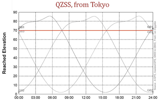
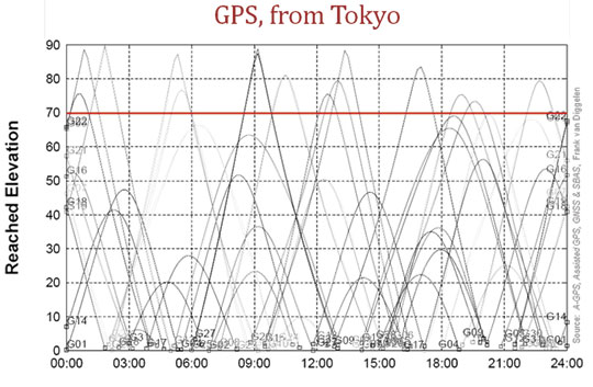
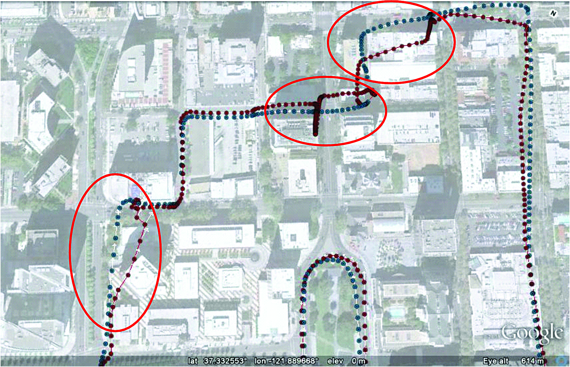


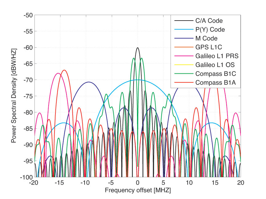
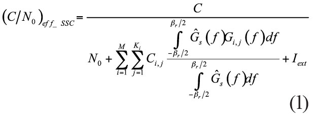
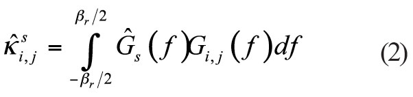
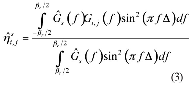
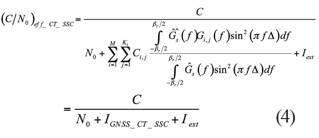
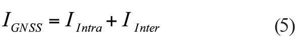


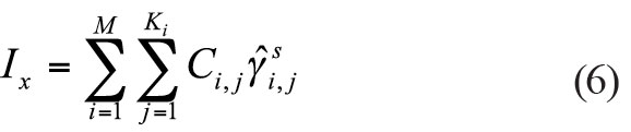
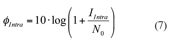
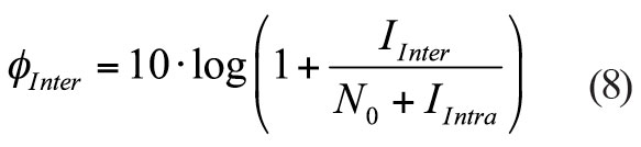
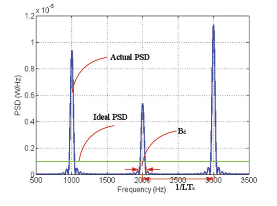
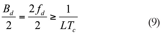
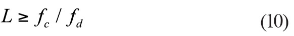
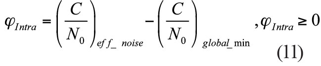
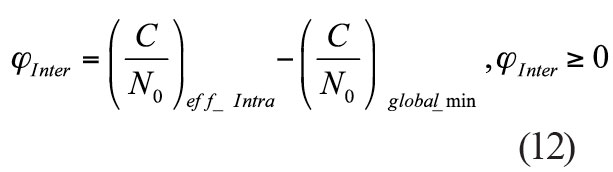
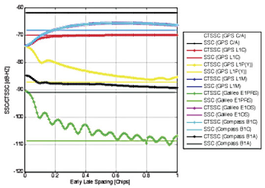
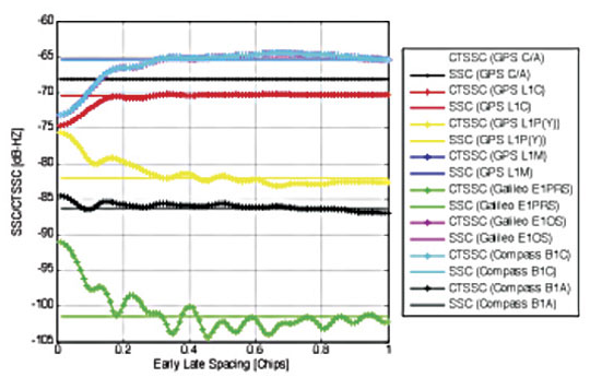


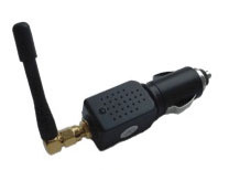
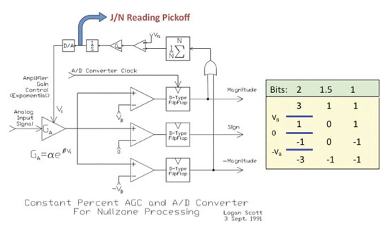
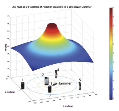
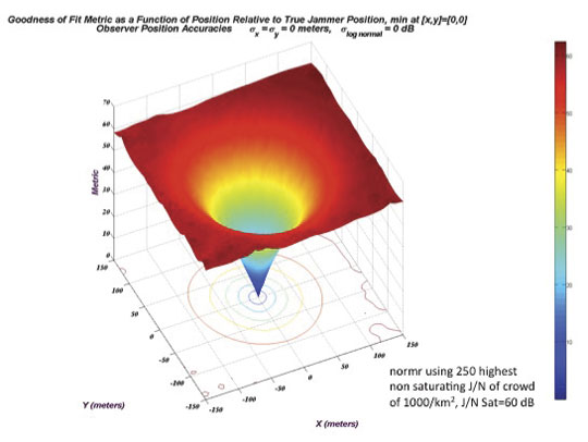
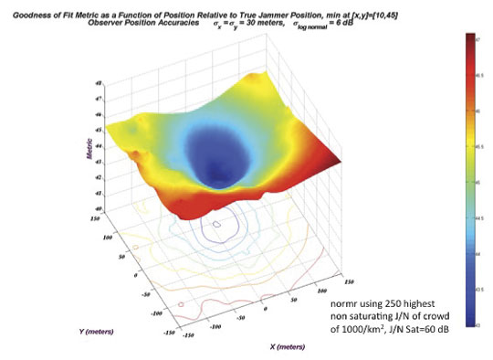
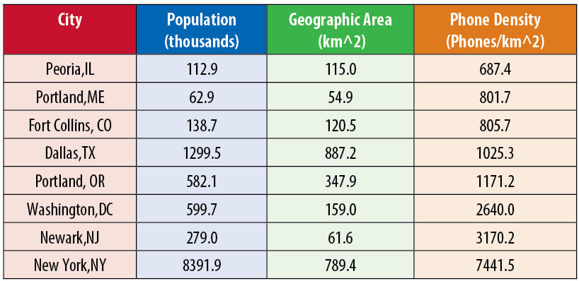
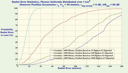
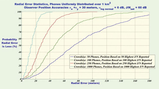
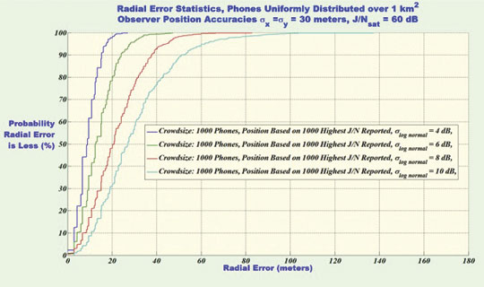
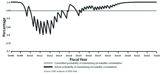
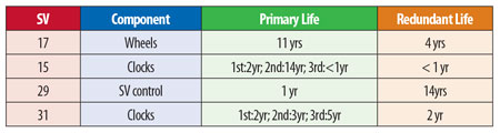
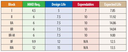
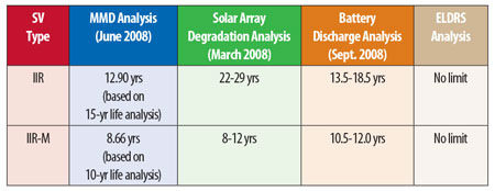
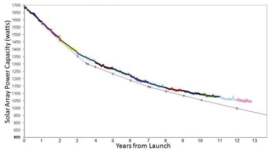
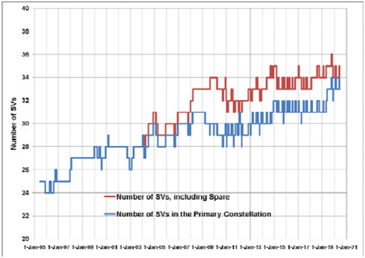
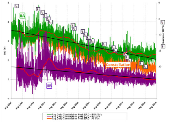
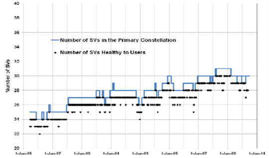
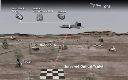
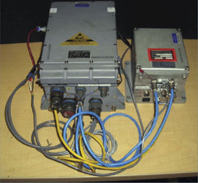
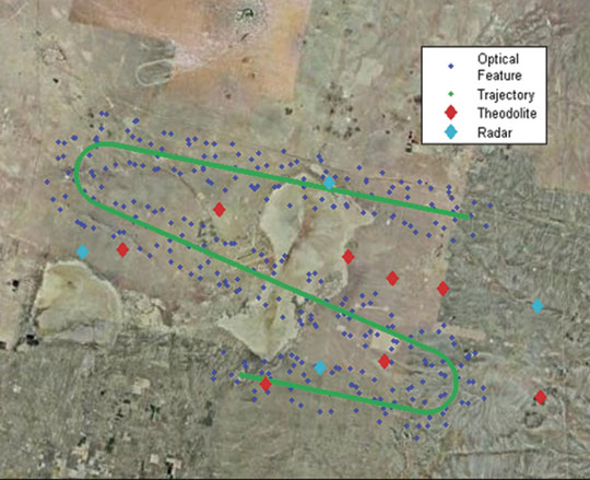
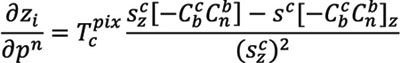
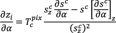
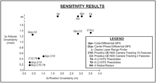

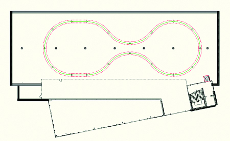
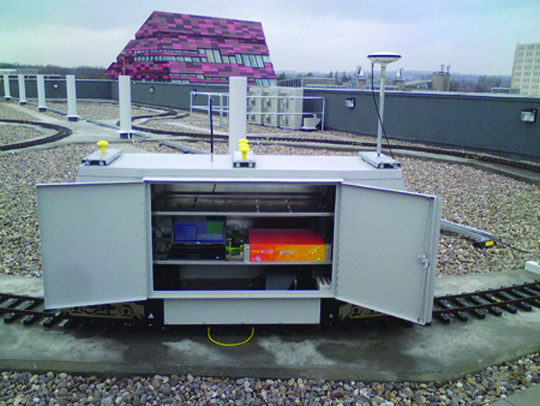