GTX Corp will begin testing its new Cat M1 LTE SmartSoles across North America, Europe and Australia, and will begin the regulatory certification process for FCC/IC and CE.
The following week will begin the device network certification with Verizon, which will be providing the cellular connectivity for the North American market. GTX will also be testing with Orange and Telefonica for connectivity in Europe and Australia.
“With over 200 back orders and increasing demand every day, we intend to begin production as soon as we complete testing and certification, expected sometime next month, and then immediately start fulfilling all pre-orders and backorders first,” said Andrew Duncan, GTX Corp. director.
The patented and award-winning GPS SmartSoles were designed to address Alzheimer’s and autism challenges, where those diagnosed are at risk of wandering and becoming lost. Wandering is a safety issue with far-reaching implications for the person with the disease, their caregiver, law enforcement and healthcare providers.
GPS SmartSoles are placed in the wearer’s shoes. They contain a Nordic Cat M1 LTE GPS module connected through cellular networks that send a GPS location to the GTX central monitoring website and app. GTX is also upgrading its tracking app both for iOS and Android.
The SmartSoles can also be used by people at risk of kidnapping, such as government employees, journalists and corporate executives. SmartSoles come in three trim-to-fit sizes for men, women, and children, are water resistant, include an inductive charging pad, and are assembled in Rhode Island.
The ION GNSS+ 2021 technical program is online, and registration for the event is now open. ION GNSS+ 2021 takes place Sept. 20-24 at the St. Louis Union Station Hotel in St. Louis, Missouri.
ION GNSS+ 2021: GNSS + Other Sensors in Today’s Marketplace, is the 34th International Technical Meeting of the Satellite Division of the Institute of Navigation, and the world’s largest technical meeting and showcase of GNSS and GNSS-related technology, products and services.
“It’s exciting to be meeting in-person in St. Louis,” said Lisa Beaty, ION executive director. “We are expecting a pent-up demand as the community is eager to convene and get caught up. The ION GNSS+ 2021 technical and commercial exhibit is the best opportunity of the year to see what’s been happening in PNT [positioning, navigation and timing].”
ION GNSS+ 2021 features more than 300 technical presentations under two technical tracks: Commercial and Policy, and Research. The opening Plenary Session will feature two keynote addresses: “Towards a Smart Digital Reality: Building a Sustainable Future,” presented by Burkhard Boeckem, and “Artemis: Return to the Moon” presented by Steven Clarke, NASA.
For those unable to attend in person, ION GNSS+ 2021 will include a virtual option. Registration offers access to all on-demand conference content, live streams of select sessions, proceedings, as well as recordings of the sessions that were live streamed during the conference. ION GNSS+ Virtual Registration includes virtual contact with ION GNSS+ exhibitors and CGSIC’s technical program.
To view the ION GNSS+ 2021 technical program and to register, go to ion.org/gnss.
Hyper Precise Location (HPL), a real-time kinematics (RTK) service, is now available via Verizon ThingSpace to customers and application developers in more than 100 U.S. markets. When paired with Verizon’s 5G Edge capabilities, HPL provides precise positioning data for emerging cellular-vehicle-to-everything (C-V2X) technology, which is necessary for certain safety applications.
Verizon recently teamed with automakers to demonstrate vehicle-pedestrian safety scenarios made possible through HPL, 5G Edge and C-V2X.
HPL is software as a service (SaaS) that provides a stream of real-time GNSS correction data to device receivers, enabling location accuracy within 1-2 centimeters, for users on 5G and 4G networks. This can enable high-scale, low-cost, centimeter-level location capabilities for industries such as automotive, HD mapping, robotics, construction, and smart agriculture (AgriTech). Designed and deployed in a privacy-protective manner, HPL does not store or share user location data.
HPL embraces open delivery standards including RTCM for its data streams, with others to be added on a rolling basis. IoT devices using HPL can be accessed and managed through a user API and the ThingSpace IoT management platform. Support resources on ThingSpace will detail API integration, coverage availability, and more.
“Hyper Precise Location stands to boost or enable next-gen technologies across industries, from intelligent-driving to drone delivery to highly automated operations within construction, agriculture, and much more,” said TJ Fox, SVP of Industrial IoT and automotive for Verizon Business. “HPL’s fast expanding coverage area, API friendliness, privacy protection, and use of open-delivery standards make it ideal for developers and customers demanding precision and flexibility.”
In August, Verizon announced it is also developing HPL next-gen road safety and highly advanced driving solutions through partnerships with location and mapping expert HERE Technologies (HERE) and Renovo, the automotive software company. HPL can also support other emerging technologies that depend on high-level location accuracy, such as delivery drones, and advanced IoT applications, such as infrastructure monitoring, critical asset tracking, and high value shipping.
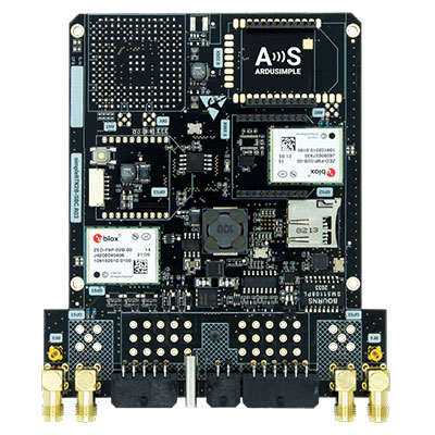
U-blox is partnering with ArduSimple, a Spanish company seeking to facilitate the adoption of centimeter-level GNSS technology for mass-market applications.
The companies partnered to develop the SimpleRTK2B single-board computer (SBC). The device, which is built around up to three u-blox ZED-F9P high-precision GNSS receivers, simplifies the development of centimeter-level positioning solutions supporting real-time kinematics (RTK), making the technology accessible to broader audiences.
The SimpleRTK2B-SBC was developed to make RTK technology as close to plug-and-play as possible. In addition to working as a stand-alone solution, customers can program their own applications with the company’s microPython API.
The SimpleRTK2B-SBC delivers mechanical integration with centimeter position on three axes (heading, pitch and roll), outputting on NMEA, RTCM, RS232 and CANBus interfaces via Ethernet, Bluetooth, Wi-Fi and 2G/3G/4G communication. It offers configurable input/output and an inertial measurement unit.
Firefighters in Slovenia. (Photo: tomazl/E+/Getty Images)
Public Safety Communication Europe (PSCE) and the European Space Agency (ESA) have signed a Memorandum of Intent (MoI) to support the use of satellite applications for public safety.
ESA and PSCE will work together under the new MoI towards establishing interoperable public safety communications systems.
The MoI will support the emergence of space-based applications in the public-safety domain such as public safety services relying on secure mobile broadband communication solutions. These include applications within disaster preparedness, response and resilience, situational awareness, assessments of damages, navigation-based services for tracking and coordinating rescue forces on-site and for emergency vehicles.
“ESA Space Solutions and the 4S Strategic Programme Line will support through this agreement the emergence of solutions making use of secure satellite communications for institutional public safety user communities,” said Rita Rinaldo, ESA. “This can be achieved as of today through existing satellite telecommunications infrastructures. In the future it will be possible to make use of new and innovative infrastructures with enhanced capabilities. Early pilots and demonstrations will showcase the unique benefits granted by satellites to the user communities and early adopters.”
“The cooperation with ESA will help to explore complementary solutions that will contribute to cover capability gaps and needs for public safety. It is of extreme importance to improve public safety communication systems with cutting-edge and rapidly deployable solutions that will facilitate PPDR missions,” explained Marie-Christine Bonnamour, PSCE.
The first step for ESA and PSCE cooperation will be PSCE participation in ongoing user studies on “Satellite Applications for Public Safety.” PSCE will help identify the needs of public safety stakeholders such as emergency services, fire brigades and law enforcement.
Trimble to provide reliable in-lane positioning for the year-long research program
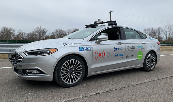
Trimble and VSI Labs have formed an alliance, with Trimble serving as the GNSS precise positioning supplier for VSI’s autonomous research vehicle program. The alliance officially kicked off in March at Destination ACM, a long-distance driving event for VSI’s research vehicle that continues with additional events throughout the year.
The collaboration provides the opportunity to showcase Trimble RTX technology as the trusted precise-positioning correction source for car manufacturers and their suppliers. Coupled with Trimble’s inertial positioning, Trimble RTX plays a pivotal role in a vehicle’s ability to maintain accurate and reliable lane-discipline during autonomous driving.
Destination ACM launched from VSI’s Minneapolis headquarters en route to the American Center for Mobility’s (ACM) test center in southeast Michigan where a day of testing and demonstration took place March 26.
“The integration of Trimble’s precise RTX positioning is a key element of VSI’s technology stack for advanced driver assistance systems (ADAS) and autonomous vehicle (AV) applications,” said Stephen Ruff, general manager of Trimble’s On-Road Autonomy Division. “VSI Labs is a leading researcher of best-in-class technologies critical to autonomous vehicle development.”
Suitable for on-road driving applications, Trimble RTX corrections operate on a single, global network. Drivers are not subject to the coverage outages that can exist when relying on local positioning systems — requiring line-of-sight to a positioning source or radio/cellular/internet connections.
When occasional obstructions are present, such as a bridge, tunnel or deep urban or rural canyon, Trimble augments its precise GNSS positioning with inertial technology to maintain continuous positioning and orientation while on the road.
Trimble’s innovative GNSS positioning is being used on the road today by a number of automotive OEMs and Tier 1 suppliers to improve the functional safety and performance of ADAS for passenger vehicles. Consumers have logged more than 7 million miles using Trimble RTX for lane-level positioning to date.
“VSI Labs is thrilled to have Trimble’s RTX technology on board,” said Phil Magney, founder and president of VSI. “Trimble’s positioning capabilities allow us to really expand our applied research on the safety and performance of autonomous and ADAS driving solutions.”
Trimble GNSS positioning technology will be used in the VSI research vehicle during each of the quarterly Destination ACM events, the Drive World Conference in Silicon Valley in August, the VSI 2021 “Drive South,” and other events this year.
For more about autonomous vehicles, see our June issue.
The United Kingdom’s National Timing Centre will conduct a two-phase series of funded studies and demonstrations focusing on “innovation in the dissemination and application of resilient time, frequency and synchronisation.”
The first round now being advertised is for feasibility studies of projects costing between £50,000 and £250,000. Total funding for the round is £2M. A briefing for interested parties will be held on April 20.
The second round and remaining funding will be devoted to technology demonstrations.
The UK’s National Timing Centre was established in response to several national studies and concerns about the vulnerability of space-based timing services.
Severe solar storms, called coronal mass ejections, were listed on the UK National Risk Register in 2012. While rare, these events can damage assets in space and on the ground.
Next month marks the 100th anniversary of the New York Railroad Storm. It was so powerful, telegraph offices were set on fire in the U.S. and Europe, fuses were blown, and equipment damaged. Even underwater telegraph cable traffic was affected.
Experts say if such a storm were to strike the Earth today, it would likely damage GPS and other GNSS satellites. At a minimum, it would charge the atmosphere and prevent signals from getting through for days.
Projects that will be considered for the UK competition must be technologies and application areas providing trust, assurance, security and resilience for time distribution.
While supported by Innovate UK, the National Physical Laboratory (NPL), which operates the virtual National Timing Centre, appears to be the primary agent for execution. NPL will offer applicants who are selected to participate in the feasibility study phase free technical consultation up to 12 hours, and free access to highly precise and accurate time signals from four NPL locations in the southeast of England.
Since its inception, the National Timing Centre seems to have concentrated on establishing distributed suites of atomic clocks, probably linked by fiber, as a first step to improving the nation’s timing resilience.
Industry observers have opined that future efforts are likely to focus on wireless distribution.
“Wireless requires less infrastructure and has no user limit,” said one. “It only makes sense they would go there once they feel they have a solid clock foundation.”
The competition is open to UK entities. Applications will be accepted April 19-June 9, with accepted participants notified on July 30.
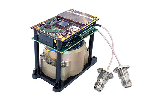
Inertial Labs has released a new generation of GPS-aided inertial navigation systems (INS) for applications such as UAVs, helicopters and lidar surveys.
The company also has released two new inertial measurement units (IMUs) for measuring angular rates and accelerations for motionless and dynamic applications.
INS-DH-OEM
The INS-DH-OEM. (Photo: Inertial Labs)
The high-accuracy INS-DH-OEM is designed for easy integration into custom enclosures and higher order integrated system applications. It combines the HoneywellHG4930 inertial measurement unit (IMU) into a GPS-aided INS to provide high-accuracy orientation, position, velocity and timing for land and aerial systems.
Consisting of three axes each of high-precision accelerometers and gyroscopes, the accuracy of the HG4930 plays a key role in the exceptional performance of the INS-DH-OEM. With input from the IMU, the INS-DH-OEM has a pitch-and-roll accuracy of 0.015 degrees real-mean-squared (RMS) for dynamic applications, and a pitch-and-roll accuracy of 0.01 degrees for motionless applications.
Another key factor for the INS-DH-OEM is its use of the NovAtelOEM7720 dual-antenna GNSS receiver. The OEM7720 is an all-constellation, multi-frequency heading and positioning solution with TerraStar PPP correction services and advanced interference mitigation features.
With aiding data from the OEM7720, the INS-DH-OEM features a 2-meter baseline heading accuracy of 0.05 degrees RMS for both static and dynamic applications. As a result, the INS-DH-OEM is a high-performance solution in line-of-sight and beyond line-of-sight antenna-pointing applications.
A reliable solution in varying environments, the OEM7720 ensures that the INS-DH-OEM is outputting the most accurate GNSS-aided data by supporting GPS, GLONASS, BeiDou, Galileo, NavIC (IRNSS), and QZSS constellations.
The INS-DH-OEM can be applied in a wide range of aerial applications such as remote sensing, flight control and photogrammetry in which the INS-DH-OEM provides accurate positioning, navigation and timing (PNT) data for multi-rotor drones, fixed-wing drones and other UAVs performing these tasks. This data is paramount in the accuracy of these applications’ deliverables such as point clouds, orthomosaics and photogrammetric plots.
Weighing 280 grams and measuring 85.7 x 62.5 x 52.0 mm, the INS-DH-OEM is a lightweight, compact system that can be fitted with custom enclosures or integrated into higher order systems such as lidar payloads. It is compatible with scanners from many lidar manufacturers: Livox, Velodyne, Ouster and Quanergy. This adaptability, coupled with top-of-the-line subcomponents and Inertial Labs’ sensor-fusion expertise, make the INS-DH-OEM the suitable for UAVs, UGVs, antenna pointing, and many more applications.
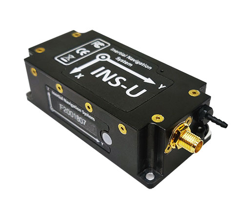
INS-U
The INS-U. (Photo: Inertial Labs)
The new INS-U GPS-aided INS with air data computer (ADC) output signal is based on a u-blox module.
The INS-U a fully integrated INS, attitude and heading reference system (AHRS), IMU and air data computer high-performance strapdown system that determines position, navigation and timing information for any device on which it is mounted.
The INS-U utilizes a single antenna, multi-constellation U-Blox GNSS receiver. With access to GPS, GLONASS, Galileo, QZSS, and BeiDou, the INS-U can be used in a variety of GPS-enabled environments and is protected against spoofing and jamming. Additionally, the INS-U is comprised of two barometers, a miniature gyro-compensated fluxgate compass, and tri-axis temperature calibrated advanced MEMS accelerometers and gyroscopes. These high-performance sensors, along with Inertial Labs’ new on-board sensor fusion filter, state of the art guidance and navigation algorithms, provide accurate position, velocity, and orientation of the device under measure.
Perhaps the most defining feature of the INS-U is its embedded ADC. An essential avionics component for modern UAV applications, an ADC outputs static & dynamic pressure, pressure altitude, calibrated & true airspeed, true angle of attack, rate of climb, and wind speed of the device under measure. This data, combined with inertial reference information, provides UAVs with accurate information about the unit and its relation to its environment.
By using data from an INS, AHRS, IMU and ADC, the INS-U provides a complete navigation solution for UAV and Helicopter applications. The unit can use time-of-flight aiding data from a ground station for long term GNSS-denied conditions as well as external position and heading so it can still output accurate PNT information regardless of the environment.
The INS-U is a lightweight and compact solution with dimensions of 82 x 40 x 26 mm and a weight of less than 200 grams. This, along with an IP67 environmental enclosure, ensures that the INS-U can meet the environmental requirements and size and weight restrictions of a wide range of applications.
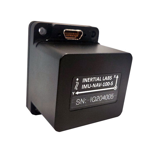
IMU-NAV-100
The IMU-NAV-100. (Photo: Inertial Labs)
The IMU-NAV-100 is a tactical grade IMU for wide range of higher order integrated system applications.
The newest addition to the Inertial Labs Advanced MEMS sensor-based family, the IMU-NAV-100, is now the best performing IMU that Inertial Labs offers. The IMU-NAV-100 is a fully integrated inertial solution that measures linear accelerations, angular rates, and pitch and roll with high accuracy utilizing three-axis high-grade MEMS accelerometers and three-axis tactical grade MEMS gyroscopes.
The IMU-NAV-100 features continuous built-in test, configurable communications protocols, electromagnetic interference protection, and flexible input power requirements which allow it to be easily integrated in a variety of higher order systems.
The IMU-NAV-100 line contains two options to accommodate a variety of projects.
The IMU-NAV-100-S is best for projects that require high performance stabilization for antenna and line-of-sight stabilization systems, motion control sensors, and platform orientation and stabilization systems. With a gyroscope angular random walk of 0.04 deg/√hr, the IMU-NAV-100-S is specialized to provide accurate data for stabilization applications.
The IMU-NAV-100-A is best used in a variety of systems such as GPS-aided INS, AHRS, and motion reference units. Regardless of the application, the IMU-NAV-100 is the company’s best performing IMU to date, providing a pitch-and-roll accuracy of 0.03 deg RMS. Fully calibrated, temperature compensated, and mathematically aligned to an orthogonal coordinate system, the IMU contains up to 0.5 deg/hr bias in-run stability gyroscopes and 0.003 mg bias in-run stability accelerometers with very low noise and high reliability.
The National Geodetic Survey (NGS) has revised an important technical document on the modernized National Spatial Reference System (NSRS). Zilkoski explores a use case on flood mapping, discussing an Elevation Certificate example, Flood Insurance Rate Map and Flood Insurance Study. NGS has scheduled a webinar for April 8 to discuss the four use case examples.
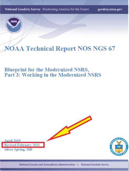
In February 2021, the National Geodetic Survey (NGS) revised NOAA Technical Report NOS NGS 67 Blueprint for the Modernized NSRS, Part 3: Working in the Modernized NSRS. Users can download the publication. See the box titled “NOAA Technical Report NOS NGS 67.”
This column will highlight one of the four use cases: “Use Case 1: Flood Mapping.” The case study discusses the Elevation Certificate (CE) example, Flood Insurance Rate Map (FIRM), and Flood Insurance Study (FIS).
The following is the scenario that NGS considered in this use case:
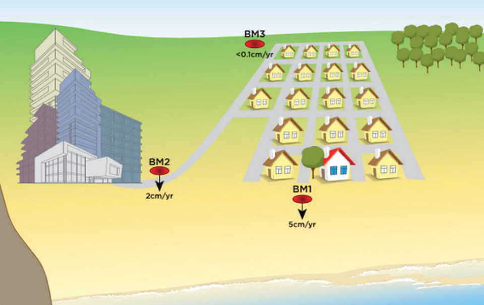
“This use case’s examples are set in an imaginary flood-prone coastal community experiencing non-uniform ground subsidence at the watershed scale (see Figure 10). Although many areas are not subject to this level of vertical motion, the full benefits of NSRS modernization are most apparent in this context. We illustrate differences in the use of the NSRS of today and the modernized NSRS with two common NFIP workflows. First, we consider steps anticipated in the certification of NAPGD2022 elevations for a NFIP Elevation Certificate. Second, we step into the shoes of a FEMA Mapping Partner to examine the ways future NSRS tools support more accurate mapping in Flood Insurance Rate Map (FIRM) and Flood Information Study (FIS) updates.”
I think this is a good scenario to use to demonstrate the full benefits of the NSRS modernization in areas of subsidence, but I believe there are important issues that will need to be addressed before the implementation of NAPGD2022 in flood mapping projects. I will highlight some of these issues later in the newsletter. First, let’s look at NGS example.
As depicted in figure 10 in NOS NGS 67 technical document, the area has three difference subsidence rates (<0.1 cm/yr., 2 cm/yr., and 5 cm/yr.). See the box titled “Diagram of fictional case study location for Use Case 1.” As NGS stated in the document, “Although many areas are not subject to this level of vertical motion, the full benefits of NSRS modernization are most apparent in this context.”
This may not be the typical situation of a flood mapping project but it should be noted that this type of high individual rates and large relative rate differences has occurred in the Houston-Galveston, Texas, region (see the following publications):
NGS’s example illustrates differences in the use of the NSRS today and the future NSRS with two common National Flood Insurance Program (NFIP) workflows. The example addresses surveyors performing a FEMA Elevation Certification using NAPGD2022 elevations, and the ways future NSRS tools support more accurate mapping in Flood Insurance Rate Map (FIRM) and Flood Information Study (FIS) updates.
It should be noted that according to the September 27, 2017, Office of Inspector General Department of Homeland Security OIG-17-110 report, FEMA’s goal is to review flood maps every five years.
“According to the National Flood Insurance Reform Act of 1994, FEMA must assess the need to revise and update all floodplain areas and flood risk zones identified once during each 5-year period. Thus, valid miles will expire every five years if not assessed. Failure to assess an NVUE compliant mile within the 5-year window will result in the mile being re-categorized as “Unknown” in the Needs Database. Unknown miles have not been subjected to the validation process to determine whether they reflect the current flood risk or are in need of restudy. In 2009, FEMA set a goal to attain 80 percent NVUE by the end of fiscal year 2014.” — Excerpt from Department of Homeland Security OIG-17-110 report
The modernized NSRS will help facilitate meeting this goal. This is described in NGS’s use case example:
NFIP products will primarily utilize the official NSRS reference epochs
“As the NFIP is structured today, NFIP products will primarily utilize the official NSRS reference epochs. Additionally, some NFIP products such as the EC form itself, as well as guidance, and technical references for FIRM and FIS preparation would benefit from updates that reflect changes to the NSRS. While the time-dependency and incorporation of a gravimetric geoid model will manifest as improved risk assessment reliability in inundation map products, we notably anticipate that NSRS modernization will have a limited impact on the basic structure of most recommended workflows associated with the NFIP of today. The most significant development is therefore the opportunity for FEMA’s National Flood Mapping Program (NFMP) to increasingly leverage the new capabilities of the NSRS to ensure that current, accurate ground elevation data is used, and to better incorporate relevant flood control structure and future conditions mapping data to support decision-making beyond the NFIP. Details of how the modernized NSRS can help FEMA achieve broader NFMP objectives and opportunities for data-driven case studies to explore this are described at the end of the use case.”
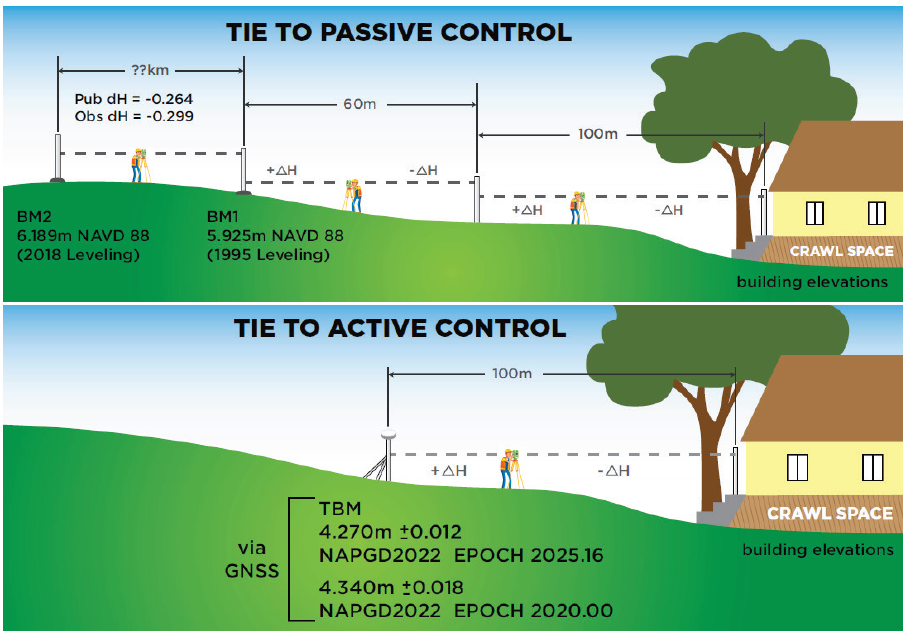
So, what does this really mean? The document uses two diagrams to explain how the new NSRS would be used to estimate a height for a FEMA Elevation Certificate (see box titled “Figure 11 from Use Case 1”). The top cartoon labeled “Tie to Passive Control” describes the process being performed today. That is, a surveyor locates the two closest marks that have published orthometric heights, follows the appropriate surveying procedures to ensure that the marks have not moved since the last time they were leveled to, and then performs the appropriate procedures to obtain the height for the Elevation Certificate. Depending on the location of the published orthometric heights in the area of the structure, this process could be very expensive. The lower cartoon labeled “Tie to Active Control” describes the process that will be used in the modernized NSRS using NADGP2022 heights. The user would occupy a temporary mark near the structure with GNSS to obtain a NAPGD2022 orthometric height computed using the appropriate ellipsoid height and geoid height value, and then perform the appropriate leveling procedures to obtain the height for the Elevation Certificate. This process will provide the most up-to-date height in the area.
Figure 11 from Use Case 1. Cartoon of Elevation Certificate field surveys based on establishing a tie to the NSRS via passive control leveling (top panel) and via active control with GNSS (lower panel). (Image: NGS)
There is an issue that should be noted here: the temporary mark determined using active control may provide the most up-to-date height at a particular location but that height may not be consistent with the heights used to establish the Base Flood Elevation (BFE). At first, someone would say, that’s good because it’s indicating that the flood hydraulics have changed on the floodplain map. However, without performing a detailed height analysis in the region, the user won’t really know whether the BFE value should be updated based on the current changes in topography in the floodplain region. In other words, if the entire region has subsidence at the same rate then the relative height difference hasn’t changed, and the new starting height may not be consistent with the published BFE on the FEMA Floodplain Map. In most floodplain mapping regions, the changes in heights are probably less than the accuracy of the maps but using the height of a mark that is not consistent with the BFE could place a homeowner’s house incorrectly in a flood zone. A good surveying practice would include occupying several marks with GNSS (or leveling between marks) that were involved in the creation of the flood insurance study and the generation of the floodplain map to ensure that the height used on the Elevation Certificate is consistent with the BFE. This is a good procedure to use for the current NSRS as well as the modernized NSRS. However, this is not economically practical using the current NSRS but could be in the new NSRS which is a major benefit of the modernized NSRS.
So, let’s look at the Houston-Galveston region using the latest information available.
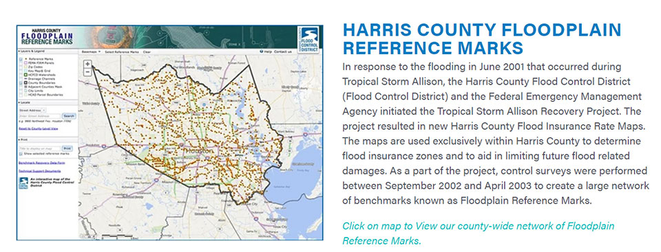
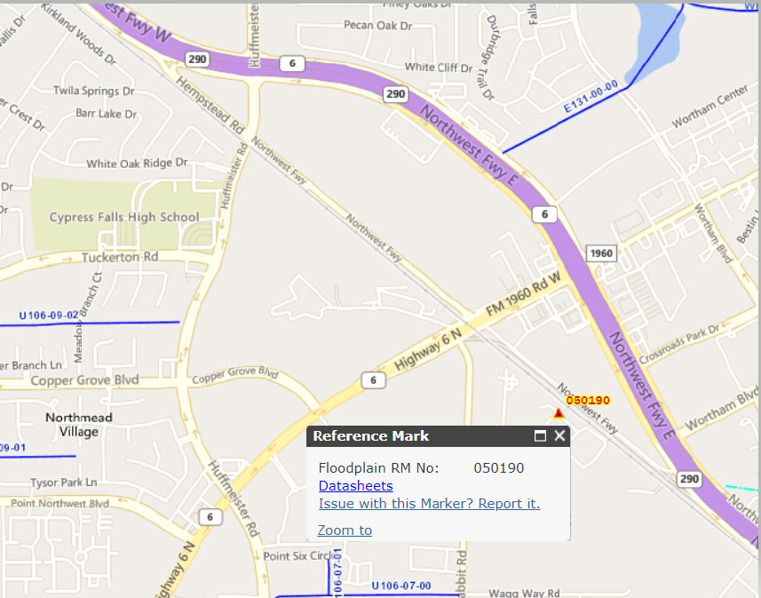
The box titled “Snapshot of Vertical Control from Harris County Floodplain Reference Marks Website” depicts the location of one of the reference marks, denoted as 050190.
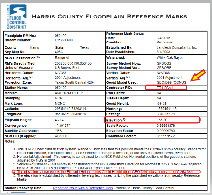
Clicking on the datasheets link, provides the information about the floodplain reference mark in the Harris County Flood Control District’s system (see the box titled “Harris County Floodplain Reference Mark Datasheet”).
It should be noted that the GNSS-derived orthometric heights were based on GEOID99 and the official hybrid geoid model published by NGS today is GEOID18. A GNSS-derived orthometric height computed using NGS’ webtool OPUS will use GEOID18 not GEOID99. The difference between GEOID99 and GEOID18 at this location is approximately 0.45 feet (0.138 meters). Users must ensure that they are using heights that are consistent with the BFE on the FIRM. The new NAPGD2022 will help to reduce issues associated with effects due to changes in geoid models.
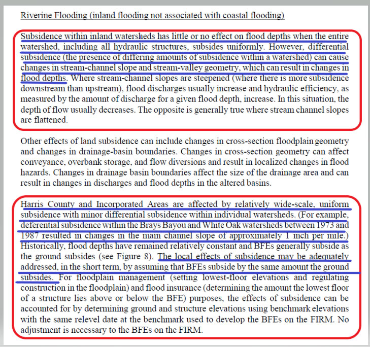
Page 113 from the November 15, 2019 Flood Insurance Study 48201CV001G addresses the issues associated with riverine flood in the region. (See the box titled “Page 113 from November 15, 2019 Flood Insurance Study 48201CV001G.”) The highlighted sections basically state that subsidence within inland watersheds has little or no effect on flood depths when the entire watershed subsides at the same rate. However, it also states that differential subsidence can cause changes in flood depths. The report goes on to say that the “Harris County and Incorporated Areas are affected by wide-scale, uniform subsidence with minor differential subsidence within individual watersheds.” It also states that “The local effects of subsidence may be adequately addressed, in the short term, by assuming that BFEs subside by the same amount the ground subsides.” The Houston-Galveston, Texas, region is a very complicated area due to the differential subsidence and numerous individual watersheds.
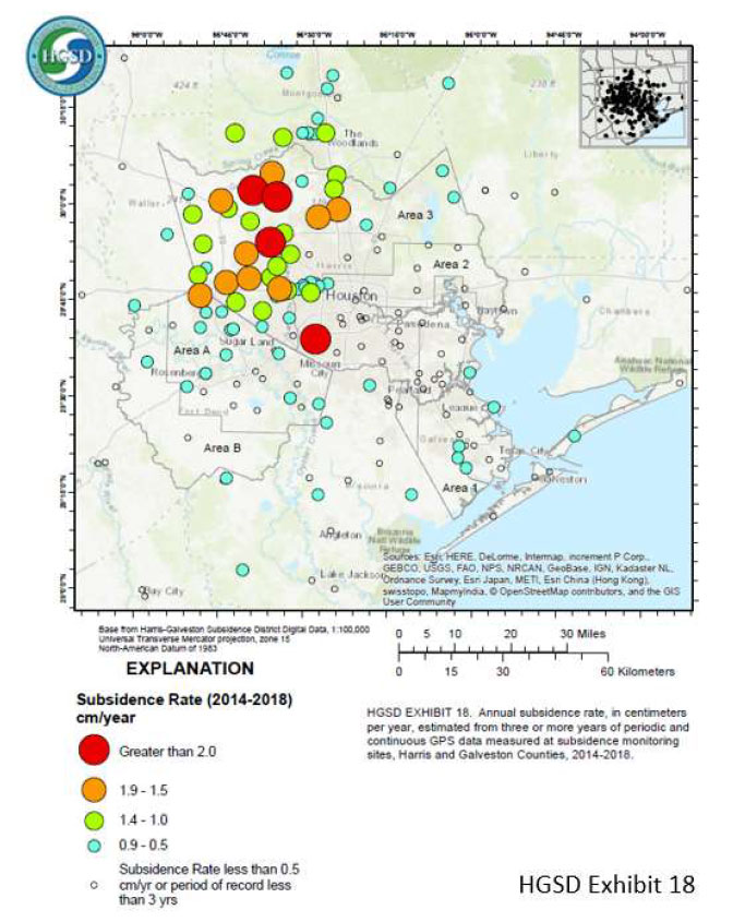
That said, let’s look some of the latest subsidence data in the region. The Harris-Galveston Subsidence District’s 2018 Annual Groundwater Report By Robert Thompson, William M. Chrismer, and Christina Petersen, PhD, P.E. provide some of the latest estimates of subsidence in the region. The box titled “HGSD Exhibit 18” depicts the locations of the GNSS sites used in the study. The plot provides the average compaction in centimeters over the past five years. The values range from 0.0 cm/year to greater than 2.5 cm/year.
HGSD Exhibit 18. This map shows the locations of the GPS sites throughout the area. The colored dots represent the average compaction over the past five years for each site, in centimeters. They range from 0.0 cm/year to greater than 2.5 cm/year. (Image: Harris-Galveston Subsidence District)
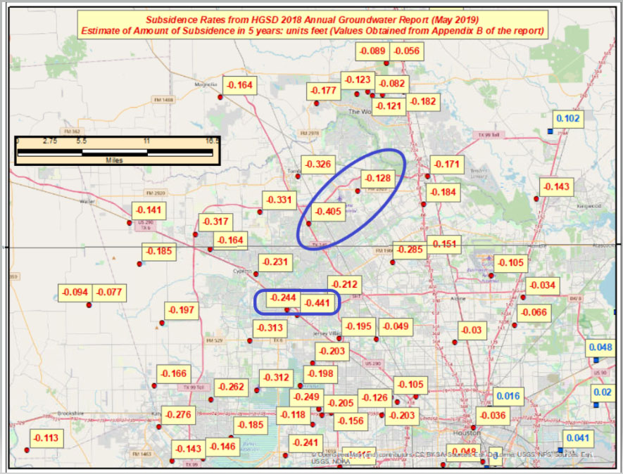
I used the information from Appendix B provided in the report to generate a few plots that show the estimate of subsidence in feet over 5 years. I’ve highlighted some marks that have large relative height changes. (Note: The units of the previous figure are centimeters; the units of the next several plots are feet.)
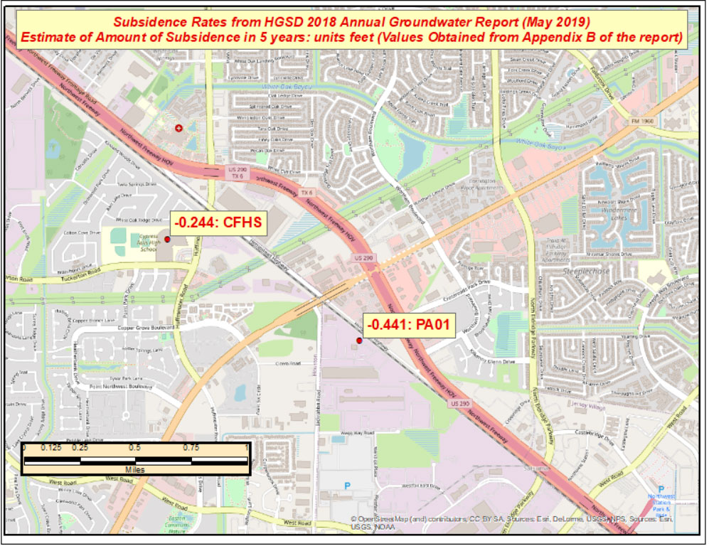
The relative height change between the two marks PA01 and CFHS, which are about 1.5 kilometers (approximately 1 mile) apart, is 0.197 feet in only 5 years. (See the box titled “Estimate of Amount of Subsidence in 5 Years at Pam 1– Units Feet.”)
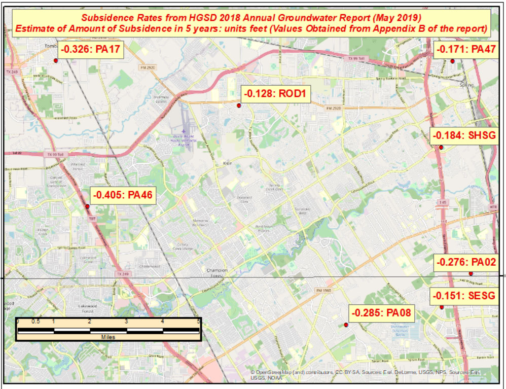
The estimated relative height change between mark PA46 and ROD1, which are about 8 kilometers (approximately 5 miles) apart, is 0.277 feet in five years. (See the box titled “Estimate of Amount of Subsidence in 5 Years at Pam 46 – Units: Feet.”)
The effect of these large relative differences may not have any effect on the BFE on a particular watershed. These subsidence estimates are at a specific mark so they only provide information at a particular location. The new NAPGD2022 along with NGS’s webtools will enable users to economically obtain current, accurate heights in the entire region. Leveraging the capabilities of the new NSRS will help facilitate the implementation of FEMA’s goal of assessing the need to revise and update all floodplain areas and flood risk zones identified once during each five-year period.
This column highlighted the potential effects of subsidence on published heights in the Houston, Texas, region, which implies that most of the published heights based on older surveys in the region are not current or accurate.
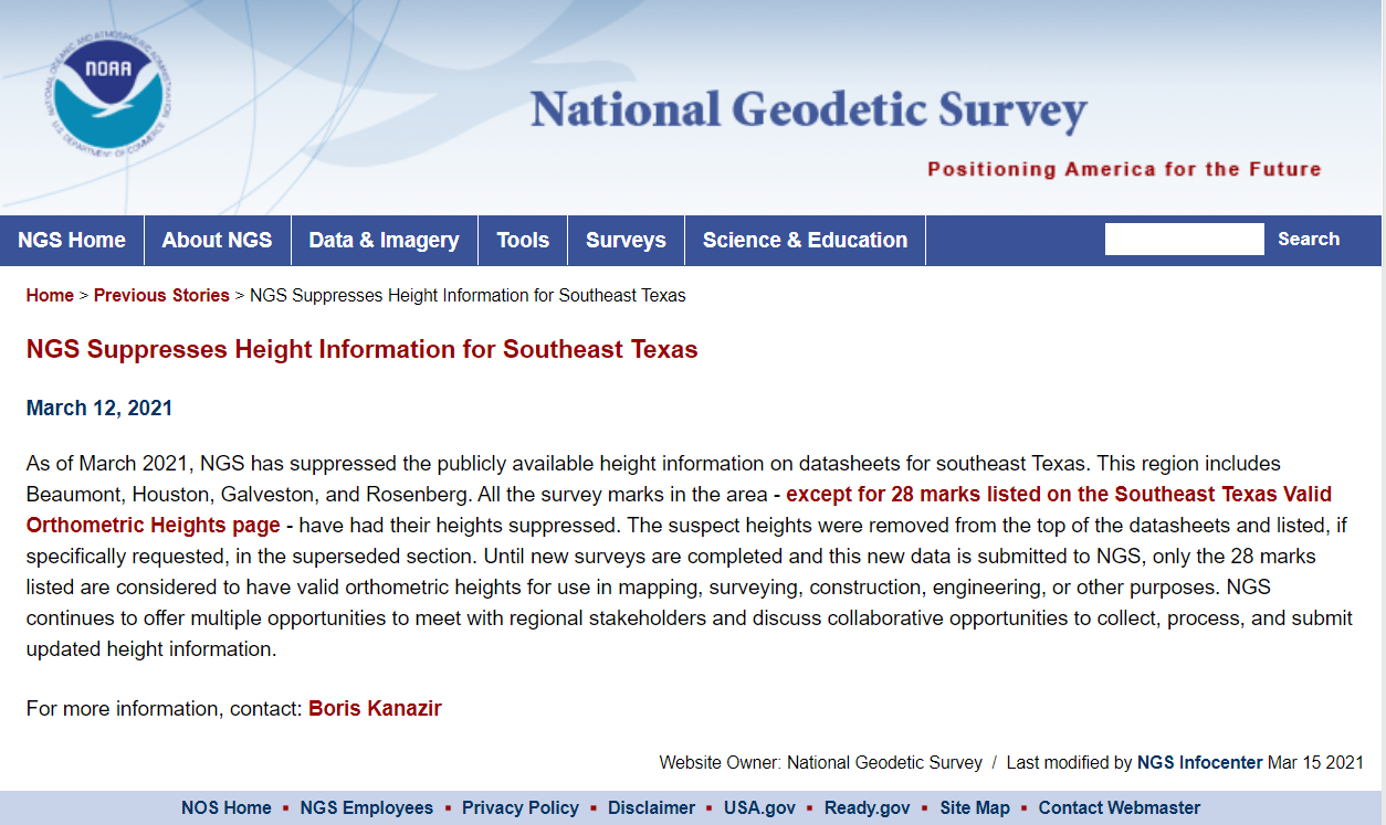
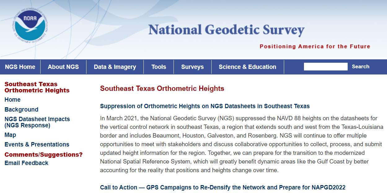
According to the announcement, only 28 marks will have publicly available orthometric heights on NGS datasheets in Southeast Texas. This NOAA website provides more information. See the box titled “NGS Southeast Texas Orthometric Heights.”
I would encourage everyone to check out the website to obtain a better understanding of what this suppression of published heights means to their operations. Future newsletters will address the suppression of the orthometric heights in Southeast Texas, and how users can help densify the network and prepare for the new, modernized NAPGD2022. Again, a benefit of the new modernized NSRS will facilitate the establishment of consistent, accurate NAPGD2022 GNSS-derived orthometric heights.
Lastly, NGS is convening the 2021 Geospatial Summit on May 4 and 5. The 2021 Geospatial Summit will provide updated information about the planned modernization of the National Spatial Reference System (NSRS). Register here.
Unmanned aerial vehicles (UAVs) are something of a Swiss Army knife for the surveying and mapping communities. Commercial applications continue to grow, with UAVS — known as drones in the vernacular — gathering data and observations for agriculture, mining, utility inspections, natural resources, historical preservation, security, and many more applications.
UAVs perform high-risk tasks that keep workers out of harm’s way. They fly in places and situations difficult or impossible for aircraft to reach. They collect high-resolution imagery across the spectrum, accompanied by exact positioning and location data. They detect and help preserve the past in rich detail.
A study by Polaris Market Research predicts the UAV market will reach $15.62 billion By 2026, spurred not only by new use cases, but through miniaturization and improvement of components. Payload components that continue to improve include GNSS receivers, inertial measurement units, micro-electromechanical components, cameras of all types (RGB, thermal, hyperspectral and high-resolution video) and lidar. (For more on lidar with UAVs, see Diving into UAV lidar surveys.)
In these pages, we share a variety of case studies from companies taking part in the UAV revolution. In many of these use cases, companies saved considerable money using UAVs rather than more traditional surveying methods. In others, UAVs are helping to keep people safe.
In all cases, using UAVs provides a wealth of data that offer new insights, no matter the application.
Every ounce counts on a drone. While a larger ground plane on a GNSS patch antenna improves its performance, the additional size increases weight — an unacceptable tradeoff.
The antenna’s location on the drone is another factor. It must be distant from motors and other electronic components that generate interference, which undermines positional accuracy. But remote locations are often off-limits because the antenna’s weight in those spots would disrupt the delicate balance drones require.
Drone-maker Parrot took these factors into consideration when choosing a GNSS antenna for its ANAFI USA drone. Although it weighs just 500 grams, ANAFI USA is designed to operate in winds up to 53 km/h.
To meet these challenges, Parrot chose the Taoglas DSGP.1575.15.4.A.02, a passive patch antenna that supports GPS L1 and Galileo E1. At 3.3 grams and 4 mm high, with a 15-mm2 footprint, the DSGP.1575 is designed for ultra-compact devices.
Key customers
High GNSS accuracy and reliability are critical for Parrot customers such as the French military, which recently ordered 300 ANAFI USA drones for reconnaissance and intelligence missions by its conventional and special forces.
Manufactured in the United States, ANAFI USA has also been selected by U.S. federal government partner organizations as part of the Blue sUAS project — the only UAV from a non-American drone manufacturer to be commercialized on the GSA Schedule, the buying platform of the U.S. military and civilian government agencies.
Police departments, federal agencies and firefighters in the United States and other countries also use ANAFI USA. The drone is also used for surveying, inspection and other commercial enterprises.
Tuned on a 50×50 mm ground plane, the DSGP.1575 operates at 1575.42 MHz with a 2.59 dBi gain. It uses ceramic materials — suitable for UAV applications because drones spend most of their time flying parallel with the horizon, a position in which ceramic antennas collect sufficient GNSS signals to meet performance requirements.
The DSGP.1575’s light weight and energy efficiency enable the ANAFI USA to carry bigger payloads and fly longer, up to 32 minutes compared to the consumer model’s 25 minutes.
“We chose Taoglas because of the quality of their antennas and their ability to tune an existing antenna in the mechanics of the product and to make it on a large scale for mass production,” said Meryam Abou El Anouar, Parrot technical leader for RF and Connectivity. “They are also known for their great experience with the GNSS propagation specificities as multipaths, so that is helpful when you try to achieve good GNSS accuracy.”
Taoglas provided Parrot with design and testing support in its design centers, as well as making regular visits to Parrot’s facility in Paris.
“Our engineering team managed to carry out tests at antenna and system levels,” said Baha Badran, Taoglas Global Antenna Technology director. “This includes passive antenna testing, in-chamber active antenna testing and GPS field testing of the drone. Each of these tests was carried out to ensure optimum GPS system performance was achieved, to give the highest possible positional accuracy for such an application.”
The support also helped Parrot minimize the cost and lead time for bringing the ANAFI USA to market.
Hexagon AB has acquired CADLM SAS, a company focused on computer-aided engineering (CAE) with artificial intelligence (AI) and machine learning. These technologies enable simulation in product-development processes and lifecycles.
Founded in 1989, France-based CADLM develops computational design and optimization methods for industrial products and processes. Since 2014, CADLM has been developing AI and machine learning solutions. Its ODYSSEE software platform applies AI and machine learning to real-world sensor data and physics-based simulation data to produce accurate, predictive models of a product at efficient computing power levels.
The combination enables faster, more efficient simulations of dynamic, multi-physics phenomena — such as automotive crash and safety — that fully characterize and understand real-world product behavior. This insight enables engineers to explore the design more extensively and interactively, and improve next-generation products without prohibitive computing cost or time.
Ola Rollén, CEO, Hexagon
Use of the digital twin beyond the early design phase enables manufacturers to leverage image recognition, predictive simulation and fault prediction to address challenges such as downtime, throughput, quality and flexibility throughout the manufacturing process.
“The convergence of CAE with advances in data management, AI, machine-learning and an increasingly connected manufacturing lifecycle is transforming the industry’s ability to address increasingly complex design challenges with rapid innovation and increased productivity,” said Hexagon President and CEO Ola Rollén. “CADLM’s AI knowledge and technology further strengthen our smart manufacturing solutions portfolio, putting data to work beyond the early design phase to improve product design innovation, manufacturing productivity, product quality and environmental sustainability through reductions in material waste.”
CADLM will operate as part of Hexagon’s Manufacturing Intelligence division. The acquisition has no significant impact on Hexagon’s earnings. Completion of the transaction (closing) is subject to normal closing conditions.