A roundup of recent products in the GNSS and inertial positioning industry from the April 2021 issue of GPS World magazine.
OEM
STL receiver
For Satellite Timing and Location service
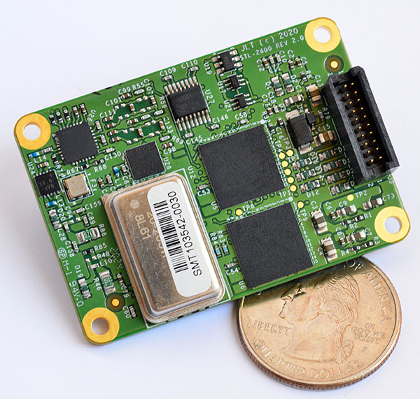
The STL-2600 Satellite Timing and Location (STL) commercial receiver was designed in partnership with Satelles Inc., the STL service provider. The STL-2600 provides a GNSS-independent, low-cost capability to generate UTC nanosecond timing and meters-accurate positioning anywhere in the world. The STL signal has 30-db (1,000 times) higher power compared to GPS signals, allowing the receiver to operate deep indoors independent of any GPS/GNSS signal. It is also useful in marine applications where GNSS signals are regularly denied or manipulated and for stationary high-accuracy timing applications such as 5G. It can be directly connected to JLT’s GPS Transcoder products for glueless retrofit capability of existing customer legacy GPS-only receiver systems to Galileo, GLONASS, BeiDou, QZSS and SBAS as well as adding the STL and optional atomic holdover capability to these legacy systems.
Jackson Labs Technologies, jackson-labs.com
Autosteering antennas
Provide high-precision accuracy
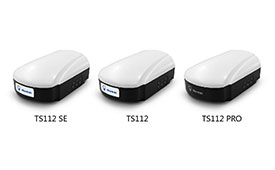
The TS112 family of smart antennas is designed for demanding applications such as agricultural machine autosteering systems that require high positioning accuracy. They offer scalable positioning solutions with increased GNSS availability, reliability and accuracy. Each of the three models embeds Harxon X-Survey four-in-one technology. The high-gain and wide beamwidth multi-constellation GNSS antennas integrate 4G, Bluetooth and Wi-Fi in a compact unit. They feature multi-point feeding technology, ensuring high phase-center stability and real-time kinematic (RTK) centimeter-level positioning accuracy. They integrate a high-precision GNSS module with multi-band GNSS receiver and Harxon’s four-in-one multifunctional GNSS antenna in a compact housing.
Harxon, harxon.com
Tactical INS
With photonic integrated chip technology
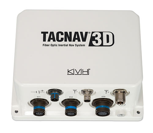
The TACNAV 3D tactical navigation system is now available with the P-1775 inertial measurement unit (IMU) featuring KVH’s new photonic integrated chip (PIC) technology. PIC technology features an integrated planar optical chip that replaces individual fiber-optic components to simplify production while maintaining or improving accuracy and performance. KVH’s IMUs with PIC technology are designed to deliver improved bias stability and greater accuracy. The fiber-optic gyro (FOG)-based TACNAV 3D tactical navigation system provides an assured positioning, navigation and timing (A-PNT) solution with an embedded GNSS and optional chip-scale atomic clock (CSAC).
KVH Industries, kvh.com
Asset tracker
Offers security features
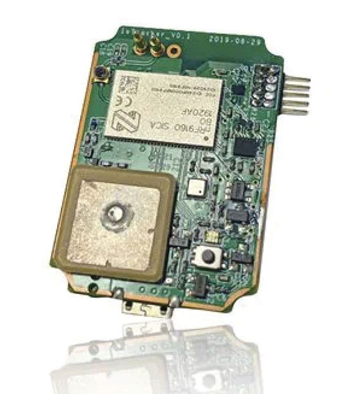
IoTeX has selected Nordic Semiconductor’s nRF9160 low-power System-in-Package (SiP) with integrated LTE-M/NB-IoT modem and GPS receiver to provide the cellular internet of things (IoT) connectivity for its Pebble Tracker. The Pebble Tracker provides trusted location, environment and motion-tracking data for global asset tracking and industrial supply chain applications. Critical features strengthen security from hacking and data corruption, meeting the demand of applications that require strong data security and integrity protection throughout the supply chain. There are two versions of Pebble Tracker. The first targets blockchain and IoT developers, while a second commercial version is designed for the asset tracking and industrial supply chain markets. The product combines an environmental sensor, a motion sensor (gyroscope and accelerometer), and an ambient light sensor. It enables cellular network connectivity and integrated GPS support in a global version supporting precise, long-range tracking of asset data using established cellular infrastructure.
IoTeX, iotex.io
Nordic Semiconductor, nordicsemi.com
SURVEYING & MAPPING
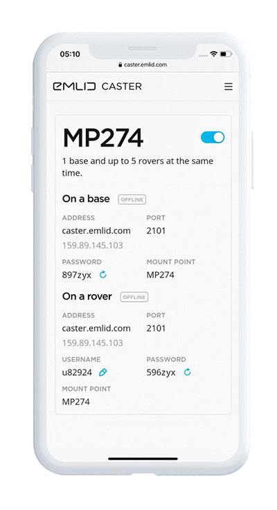
NTRIP caster
Enables transmission of corrections via the internet
Emlid Caster is an easy way to transmit corrections between real-time kinematic (RTK)-capable devices via the internet. Emlid Caster has a simple interface. Users can create their personal mount point and connect one base and up to five rovers. It works not only with Emlid products but any other device supporting NTRIP. For example, users can pass RTK corrections to the DJI Phantom 4 RTK drone from the Reach RS2 receiver as a base station. Emlid Caster is free and available worldwide. Once signed up, personal NTRIP credentials are generated automatically for a base and a rover.
Emlid, caster.emlid.com
Entry-level software
For construction surveying
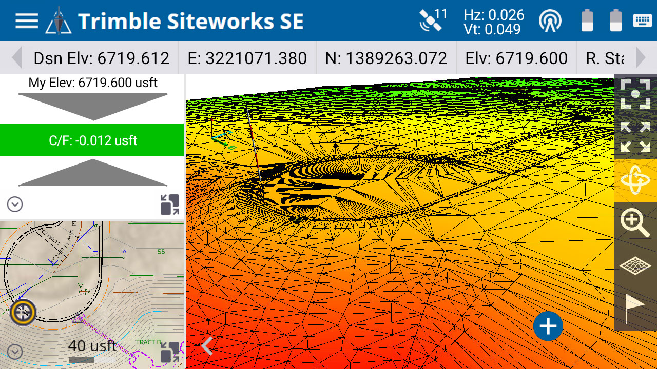
The Trimble Siteworks SE Starter Edition is an entry-level construction surveying software program. With the program and a construction GNSS receiver, a supervisor, foreman, grade checker or site engineer can easily check a grade, slope or alignment and navigate the project more accurately and in less time than with traditional survey methods. It also can give more personnel on the jobsite access to survey technology, enabling more productive and efficient field crews. Trimble Siteworks SE Software is a simplified version of Trimble Siteworks Software, intended for users who do not require a full feature set and are interested in a lower-cost version to connect to GNSS only. Contractors can easily upgrade to the full version.
Trimble, trimble.com
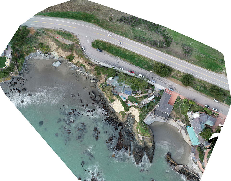
Low-altitude mapping
Flexibility for all flying parameters
The Leica CityMapper-2L configuration is designed for airborne urban mapping projects at low altitude operation. Lower flying heights can be required by air traffic control (ATC) restrictions and in areas with low cloud cover. It features a 71-mm focal length at nadir, suitable for 5-cm ground sample distance (GSD) data acquisition at flying heights of 940-m above ground level. The new lenses offer similar coverage and productivity for a specific GSD as existing configurations for standard and high-flying heights, while significantly expanding the operation envelope. The CityMapper-2 hybrid airborne sensor combines oblique imaging and a lidar in one system. The sensor efficiently creates digital twins of cities. The system includes two 150 MP nadir cameras (RGB and NIR), four 150 MP oblique cameras and a 2-MHz linear-mode lidar sensor.
Leica Geosystems, leica-geosystems.com
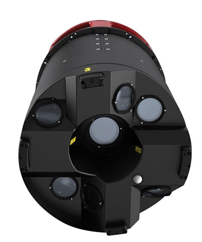
Lidar dataset
Full-waveform flash data for autonomous vehicle development
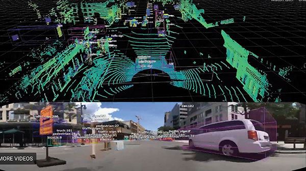
Leddar PixSet is a publicly available sensor dataset for advanced driver assistance and autonomous driving research and development. The dataset includes full-waveform data from LeddarTech’s Leddar Pixell, a 3D solid-state flash lidar sensor. LeddarTech is offering these datasets free of charge for academic and research purposes. It allows academic and engineering research teams specializing in advanced driver-assistance systems (ADAS) and autonomous driving technology to use existing sets of sensor data to test and develop advanced software and to run simulations without having to assemble new sensor suites and collect their own dataset. An instrumented vehicle was utilized in the development of the dataset. The various scenes were recorded in high-density urban and suburban environments as well as on the highway.
LeddarTech, leddartech.com
UAV
Lidar surveying
High-resolution scanning
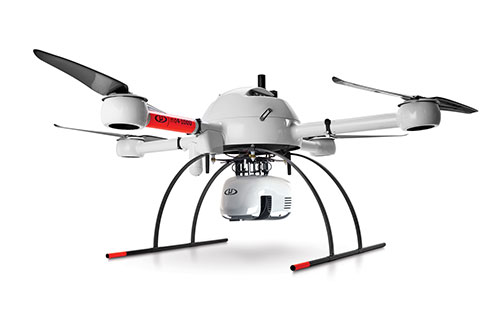
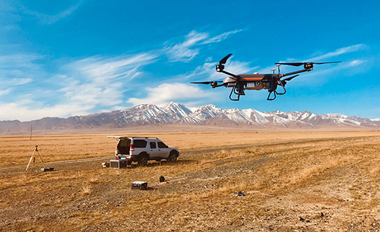
The mdLiDAR1000HR aaS drone lidar survey package is designed for professionals responsible for geospatial data collection, such as corridor mapping, mining (volume calculation), construction site monitoring, recording environmental changes over time, forestry, contour mapping, archaeology and cultural heritage, and more. The drone lidar system has a 90° field of view for both scanned points and imagery. It repeatedly provides a precision of 1.6 cm (.052 feet) when flown at 40 m (130 ft) at a speed of 8 m/s (18 mph). It integrates the Velodyne Puck Lite lidar sensor.
Microdrones, microdrones.com
Agriculture drone
Helps assess crop health
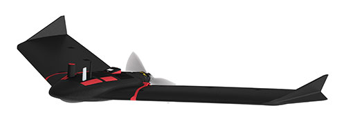
The fixed-wing eBee Ag drone can provide a complete assessment of a farm and crops faster than traditional field scouting. With its dual-purpose Duet M camera, eBee Ag captures accurate RGB and multispectral data that enable farmers to effectively assess crop health and help catch early indicators of pests, diseases and weed infestations that threaten crop yields. It features real-time kinematic (RTK) functionality for greater mapping precision. With its available RTK, the drone can achieve absolute accuracy down to 2.5 cm (1.0 inches) with RGB. Highly accurate index maps allow farmers to understand each acre while managing problematic areas field-wide.
SenseFly, sensefly.com
Lidar products
Include new terrain software module
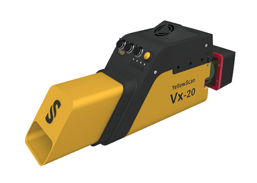
The Vx15-300 and Vx20-300 UAV lidar solutions are new additions to Yellowscan’s Vx product series. A new terrain software module allows users to automatically classify grounds from off-ground, as well as export various digital elevation models. Both integrate the Riegl Mini-VUX 3 airborne laser scanner (1.55 kg / 3.4 lbs), designed specifically for integration with UAVs. The scanner offers a selectable 100-kHz, 200-kHz and 300-kHz laser-pulse repetition rate (PRR). At 300-kHz PRR, the sensor provides up to 100,000 measurements per second at 120° field of view, and thus a dense point pattern on the ground for UAV-based applications that require the acquisition of small objects.
Yellowscan, yellowscan-lidar.com
TRANSPORTATION
Vaccine container
GPS tracking ensures custody chain remains intact
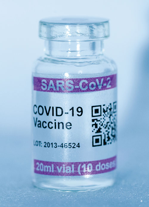
Cryo-Vacc containers use helium — a fraction of the weight of nitrogen — to provide safe transportation of vaccines at the required extremely low temperatures and for periods of up to 30 days, without the need for any power supply. Now in prototype, the containers work with both air and ground transportation. A temperature range of -150°C to 8°C, makes it versatile for a range of vaccines — including those for COVID-19 — that need to be transported for up to 25 days or longer in transit, where access to an external power source is not possible. Combined with cold-chain monitoring and asset tracking technology from Beyond Wireless (a World Health Organization-certified provider), Cryo-Vacc can provide accurate temperature readings of vaccines in transit, as well as GPS-based tracking to ensure the custody chain can be audited.
Renergen, renergen.co.za
Data logger
Multiple parameter sensing for transportation
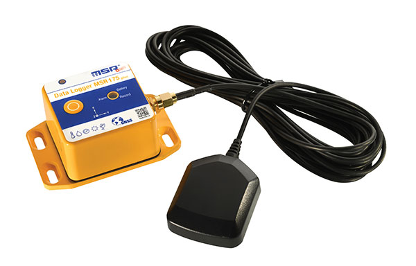
The tamper-proof MSR175plus GPS data logger records potentially damaging shock events as well as the associated ambient conditions with the exact geographic position via its GPS/GNSS receiver. It contains two 3-axis-acceleration sensors (±15 g/±200 g), a temperature sensor (-20 to +65° C), a humidity sensor (0 to 100% relative humidity), air pressure sensing (0 to 2000 mbar), and an ambient light sensor (0 to 65,000 lux). It helps ensure compliance with transport specifications and provides irrefutable data for identifying damage liability for help with insurance claims. An external connector is ready for a cable-connected antenna. The removable, rechargeable 2400 mAh LiPo-battery enables recording for up to 8 weeks (at least one year without GPS-based tracking).
MSR Electronics, www.msr.ch