“Seen & Heard” is a monthly feature of GPS World magazine, traveling the world to capture interesting and unusual news stories involving the GNSS/PNT industry.
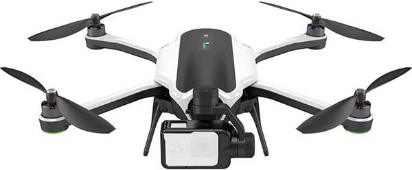
Photo: Karma drone/GoPro
Bad karma
The GoPro Karma drone has been grounded since the new year began, reports The Verge. Multiple owners say their Karma controllers are flashing errors about not receiving a GPS signal, and that they can’t calibrate the compass. They’re not able to fly the drones even after disabling GPS. A GoPro spokesperson told The Verge that it is “actively troubleshooting” the issue.
Going wild at the casino
A Waze ad in January misdirected drivers headed to Atlantic City’s Borgata Hotel Casino & Spa into New Jersey’s Pine Barrens. Jackson Township police helped numerous motorists stuck on unpaved roads about 45 miles from the casino, which is just off the Atlantic City Expressway. The address on the ad was correct, but the location pinned with the ad is actually in the Colliers Mills wildlife area.
Photo: Rock penguins/Charles Bergman/Shutterstock.com
Feed the birds, not the mice
Irish structural engineer John Houston used a Trimble R10 GNSS receiver and Centerpoint RTX to help mitigate a serious threat to Gough Island’s birds. The Royal Society for the Protection of Birds seeks to eradicate invasive mice left from 19th-century ships. The survey will help locate temporary infrastructure for workers to distribute poisoned bait to kill the voracious rodents, which feed on two million defenseless eggs and chicks each year. Though 1,000 kilometers from the nearest reference station, Houston achieved centimeter accuracy on all survey points. See the monster mice here.
Photo: U.S. Marines at Al Asad Air Base in 2018. (Cpl. Jered T. Stone/Marine Corps)
Missiles guided by GLONASS
According to Israeli military intelligence website DEBKAfile, Russia gave Iran access to GLONASS to target the U.S. base in Iraq on Jan. 8. The strike injured 34 American soldiers. DEBKAfile reports that Russia-provided GLONASS access allowed Iranian missiles to hit with an accuracy of 10 meters at the Ain Assad base in western Iraq. “According to Russian sources, 19 missiles were fired from the territory of Iran, 17 of which hit the targets,” DEBKAfile said.
How do we ensure that GPS is protected from harmful interference?
By J. David Grossman, guest columnist
J. David Grossman
Debates in Washington over harmful interference and the coexistence of divergent services are raging. Nowhere are the differences more apparent than when comparing radio navigation services such as GPS to radio communications systems used in wireless communications networks.
How do we ensure that a satellite-based radionavigation service like GPS, which by design operates below the ambient noise floor, is protected from harmful interference? The International Telecommunications Union’s (ITU) definition of harmful interference provides a starting point, by defining harmful interference as a level that “endangers the functioning of a radionavigation service.”
With this foundational definition, the internationally established criterion of a 1-decibel (dB) increase in the noise floor, otherwise known as the 1-dB standard, provides the answer, offering a readily identifiable, objective and predictable metric.
The 1-dB standard uses a 1-dB increase in the noise floor as the distinction between the onset of interference that can be detected by a GPS receiver and harmful interference. (This can be reliably measured by a 1-dB decrease in the carrier-to-noise ratio, C/N0, reported by the receiver). Thus, the 1-dB standard provides a definitive way to protect GPS receivers from harmful interference. Adherence to this standard helps ensure that systems operating in an adjacent spectrum band do not interfere with GPS.
Why use the 1-dB standard instead of other metrics? The 1-dB standard is based upon well-understood GNSS engineering considerations and is associated with quantifiable changes in the overall noise to which GNSS receivers are subject, with equally well-understood effects on receiver operation. (The 1-dB standard enables system designers and spectrum regulators to carefully assess interference from various sources and analyze their net effect on GNSS receivers).
It also has been adopted internationally and has a long and well-established proven history of protecting GPS operations from harmful interference in both international and domestic regulatory proceedings.
So-called “alternatives” to 1 dB, which may be appropriate in the context of radio communications systems, fail to recognize that the accuracy, integrity and reception (availability) of GPS signals used by a receiver can be degraded by interfering noise in ways not immediately apparent to an end user. This means that the effects of degraded service of GPS signals can still be detrimental well before the user loses position accuracy or experiences complete loss of position.
Additionally, C/N0 is computed at the entry point of a GPS receiver, such that a 1-dB decrease serves as an early warning of interference potentially becoming harmful. Other metrics, computed further downstream, may be indicative of harmful interference already occurring.
GPS has become a fundamental part of our lives and is an integral engine of the U.S. economy, creating new jobs, and unlocking innovation. Maintaining the 1-dB standard ensures that the GPS success story and American innovation will continue for decades to come.
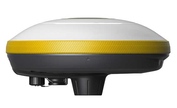
The interface adopts a concealed design for better protection, and USB type-C charging and transmitting is a two-in-one function.
The magnesium-alloy body is rugged and the battery level can be checked with a unique LED power indicator. The weight of the whole receiver is 940 grams.
The E300 Pro supports satellite station differential and satellite chain life, quick connection, intelligent voice, and tilt compensation. The E300 Pro tracks GNSS with 700 channels and fully supports BDS-3 signals. It supports 31 frequency points, using all GNSS satellite systems and frequency bands.
Inertial integration. The E300 Pro integrates multiple sensors including GNSS, an inertial measurement unit (IMU) , a magnetometer and a thermometer. With the help of a Kalman filter algorithm, the device can dynamically output position, speed and attitude information. It can measure and make real-time dynamic sampling without the need for leveling.
Combined GNSS Antenna. For better radio signal quality, the E300 Pro integrates GNSS, Bluetooth, Wi-Fi, 4G main and auxiliary antennas on the top of the receiver to ensure the best reception in all directions. An innovative RF connector greatly improves connection reliability, while reducing loss of gain.
Founded in 2005, e-Compass provides data acquisition and positioning equipment including high-precision GNSS receivers, GIS data collectors and combined inertial navigation products.The company is based in Shanghai, China, with offices in the United Kingdom and Hong Kong.
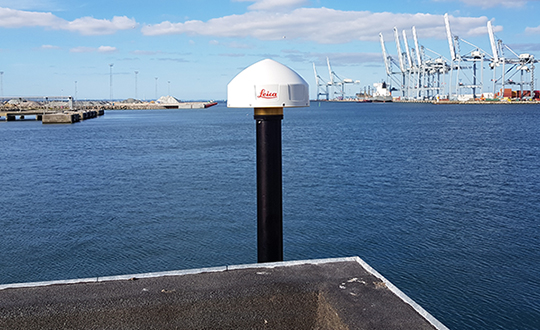
Rooftop view of the central parts of Aarhus with the harbor area and the sea in the background. (Photo: DTU Space)
A testbed in an active urban center can show real-world effects on GNSS as an aid for developing autonomous systems for green mobility, smart-city applications or transportation, to name a few.
Sited in Denmark, the 600-square-kilometer Testbed in Aarhus for Precision Positioning and Autonomous Systems (TAPAS) covers both a densely populated city center and suburbs, a large industrial harbor and parts of Aarhus Bay. Aarhus is the second largest city in Denmark with a population of 350,000 people.
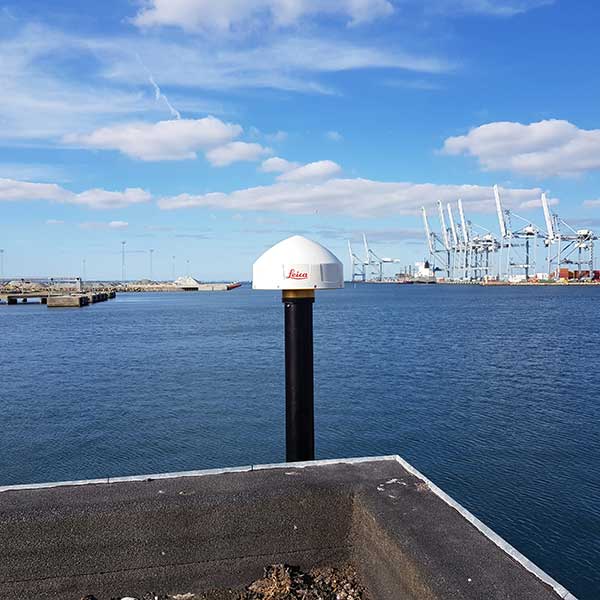
The GNSS antenna at TAPAS station TA01. (Photo: DTU Space)
Based on RTK methodology, TAPAS is a sound ground-based testbed to support, test and validate technological developments with a need for fast, efficient, flexible and reliable precision positioning. It is designed as a geodetic innovation platform, with both physical and virtual networks providing positioning to the centimeter (cm) level.
Autonomous systems within transportation, agriculture and environmental monitoring constitute a large growth area for businesses and governments. Automated vehicles, drones and vessels are linked closely to geodetic infrastructure and communications networks such as 5G. TAPAS provides developers in these fields with opportunities to observe GNSS in urban canyons and under canopies, as well as challenges for coastal marine applications. The testbed is available for third-party research projects, and testing of ideas, initiatives and concrete prototypes.
TAPAS is fully funded and owned by the Danish Agency for Data Supply and Efficiency (SDFE), the Danish agency for geodesy and geographical data. TAPAS is developed by the National Space Institute at the Technical University of Denmark (DTU Space), and is supported by the city of Aarhus. The TAPAS testbed was established partly because of Denmark’s National Space Strategy, which points to the new technological development within positioning, as well as possibilities for use of Galileo, the European GNSS, to the benefit of as many citizens as possible.
In this article, we review the TAPAS testbed, including design and installation of the GNSS reference stations and the data-processing center, as well as initial performance testing carried out by DTU Space.
Network of GNSS Reference Stations
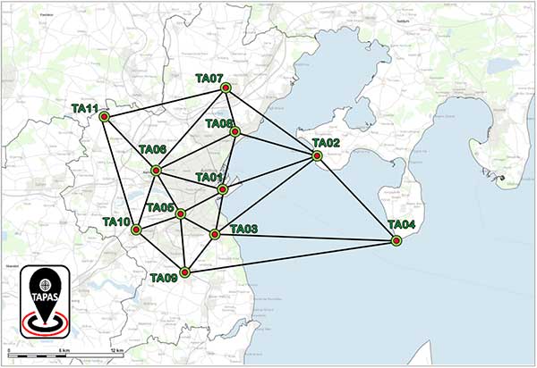
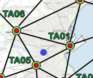
The network of TAPAS stations in and around the city of Aarhus in Denmark. (Map: DTU Space)
The basic component of TAPAS is high-accuracy carrier-phase-based GNSS positioning using the network RTK methodology, which can provide real-time position accuracies for the end user down to the cm level.Essentially, TAPAS is based on a network of 11 GNSS reference stations as well as data communication infrastructure, a central processing facility with a data server, processing software and data storage.
TAPAS was designed to provide real-time position uncertainties for objects in motion within 1 cm in three dimensions (1 cubic cm), for end users with modern GNSS equipment. A dense network of GNSS reference stations was originally designed with stations 5 km apart in the city center and up to 10 km apart in the suburbs.
Because suitable locations had to be found, in the final network distances range from 4.1 km to 22.3 km, with the longest distances across the water to station TA04 (see the network plot in the graphic above).
Stations TA01, TA03, TA05, TA06 and TA08 are in the city center. Stations TA02 and TA04 are across Aarhus Bay, ensuring coverage for marine applications and contributing to more robust positioning near the sea and in the harbor area around station TA01.
TAPAS Stations
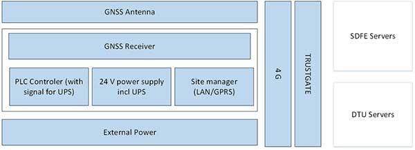
The TAPAS GNSS reference stations are equipped with the newest generation of GNSS receivers and antennas capable of tracking all available signals from the GPS, GLONASS, Galileo and BeiDou systems. The stations also have an antenna splitter, power supply, fuse box, programmable logic controller (PLC) for monitoring and control, trustgate, modem and uninterruptible power supply with battery pack (Figure 1). All units were integrated in the cabinets and tested in the lab before installation The stations are modular and flexible for future iterations and updates.
The receivers can be accessed remotely via a VPN line to a web interface for monitoring, changing settings or firmware updates. All TAPAS stations transmit data to servers at DTU Space where the data is used for estimation of RTK corrections. Also, data is transmitted to servers at the SDFE for storage and backup (Figure 1).
Figure 1. Design schematics of the TAPAS stations. (Image: DTU Space)
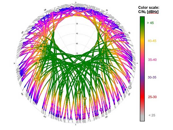
After installation in the fall of 2018, GNSS data quality was verified for each station by estimating preliminary positions and analyzing data quality. Also, signal strength as given by the carrier to noise ratio (C/N0) of the received signals was analyzed and plotted with 24 hours of data from each of the stations (Figure 2).
Network Real-Time Kinematic (RTK)
Data from the TAPAS stations streams in real time to the Central Processing Facility (CPF) operated at a dedicated server at DTU Space in Lyngby, North of Copenhagen. The GNSS observations are processed using the GNSMART 2 software from Geo++, where corrections for network RTK positioning are estimated. The corrections are estimates for errors affecting the GNSS positioning, such as inaccuracies in satellite positions and clock drift parameters as well as ionospheric and tropospheric effects. The dense network of reference stations in TAPAS will assure that corrections for the atmospheric effects will be of very high quality.
For estimation of the RTK corrections, standard software settings are used. All corrections are estimated by a state space representation (SSR) technique, where error sources are modeled individually. This means TAPAS can deliver both RTK corrections and corrections for precise point positioning (PPP).
TAPAS corrections are generated in the RTCM format and output using the NTRIP protocol. Registered users can access the corrections through the internet via an NTRIP caster. On the user side, the TAPAS corrections are applied in the positioning process of a GNSS receiver. To make full use of the TAPAS data, user equipment should be capable of tracking carrier-phase-based GNSS data and applying the TAPAS correction data supplied in the RTCM version 3.x format.
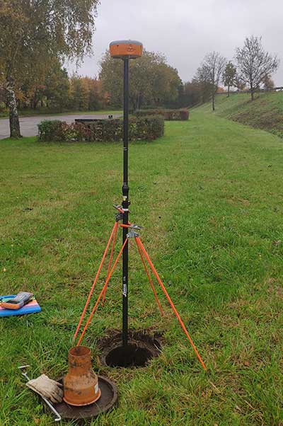
An example of a use of TAPAS is provided in the photo in Figure 9 below where the authors of this article tested the position accuracy of TAPAS for a typical land surveying task, using a Septentrio Altus APS3G receiver with an allegro2 controller unit for RTK positioning. The user’s GNSS equipment can, however, be many other different types and makes of GNSS antennas and receivers, and the equipment can be installed on many different platforms for instance in vehicles, on drones, in robots etc.
Geodetic Basis
When determining positions with uncertainties at the 1-cm level, it is important to be aware of the geodetic reference frame used for the positioning. In this case, coordinates for the TAPAS stations have been estimated by DTU Space, using Bernese GNSS software, in the national Danish reference frame which is a realization of the European Terrestrial Reference System (ETRS).
When applying corrections from the TAPAS caster in the positioning calculations at the user side, positions will be obtained within the same reference frame (coordinate system). In this case, where the national geodetic reference frame is used, this means that the user will obtain positions compliant with maps, charts and other types of geodata geo-referenced in the same coordinate system.
For 3D positioning, the Danish geoid model must be applied on the user side to obtain heights relative to mean sea level in the national Danish Vertical Reference (DVR90).
It is possible to configure the setup of the central processing facility using another reference frame for TAPAS given that precise coordinates for the TAPAS stations can be provided in the given reference frame. Future work with TAPAS can involve the use of dynamic geodetic reference frames and transmission of coordinate transformation parameters to the users.
Performance Testing
After the stations were installed, DTU Space conducted performance testing, including testing data communication between the TAPAS stations and the TAPAS server, analyses of data completeness from the TAPAS stations, and field tests carried out after the network RTK processing had become sufficiently stable.
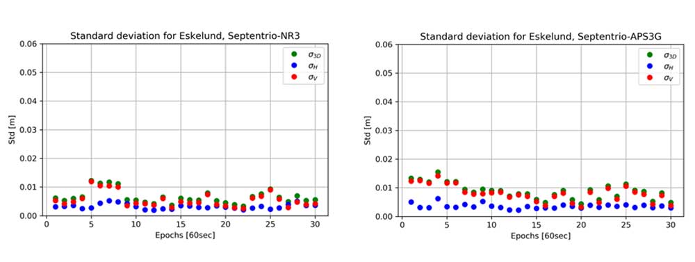
Performance test in static mode. In February 2019, a static mode test took place in a park-like area within the three innermost stations. Two different high-accuracy survey-grade RTK-receivers were used for the field test. RTK positions were estimated at 1 Hz for 30 minutes. For each minute, an average position was calculated based on the 60 observations, and for each of the minute-bins the standard deviation with respect to the reference position was computed.
Test location indicated with purple circle in the network plot. (Image: DTU Space)Altus APS3G unit mounted at the test location. (Photo: DTU Space)
The results are shown in the plots below, where standard deviations are provided for each epoch (i.e., for each bin of 60 seconds).
Standard deviation in meter for each 60 second with GNSS receiver Altus NR3 (left) and Altus APS3G (right). Results provided in meter. (Images: DTU Space)
In the plots, results are provided for the vertical (red), the horizontal (blue) and the 3D position (green). Results of using the two different receivers are comparable, and focusing on the 3D solutions the largest standard deviation is 1.6 cm which is for the fourth epoch with receiver APS3G. Most of the 3D results shown in the plots are better than 1 cm.
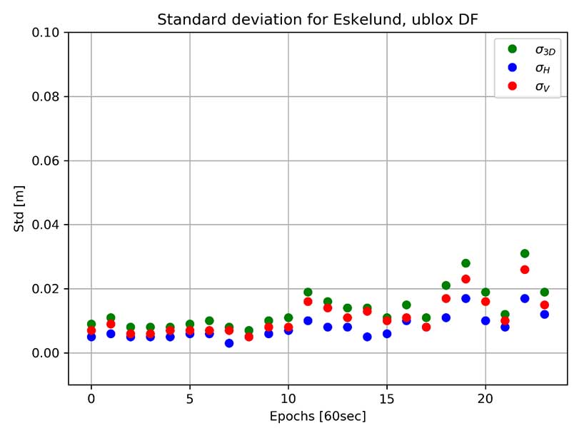
The same test was carried out using a dual-frequency non-survey-grade receiver developed for machine control and autonomous vehicle applications. This receiver was connected to the same antenna mounted on a tripod. Results of using this receiver in static mode are shown in the plot below. In this case, the 3D results are all better than 3.1 cm, and many of the 3D results are better than 1 cm in this open test area.
Standard deviation for each 60 second with GNSS receiver u-blox F9P dual frequency (DF). Results provided in meter. (Image: DTU Space)
Performance test in kinematic mode. In the same area used for the static test, a kinematic test was carried out with the same three receivers.
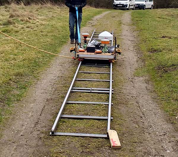
The test was performed using a camera dolly and by placing approximately 10 m of rail on the ground. The camera dolly was pulled back and forth along the rail, a setup that provided a stable trajectory for testing positioning performance while the GNSS antennas were moved slowly and smoothly. A rigid bench, where the GNSS antennas could be mounted, was constructed and installed on the dolly. The three GNSS receivers with antennas were mounted on the bench, and the dolly was pulled back and forth along the tracks 10 times.
Kinematic Test: Camera dolly with GNSS equipment pulled along tracks. (Photo: DTU Space)
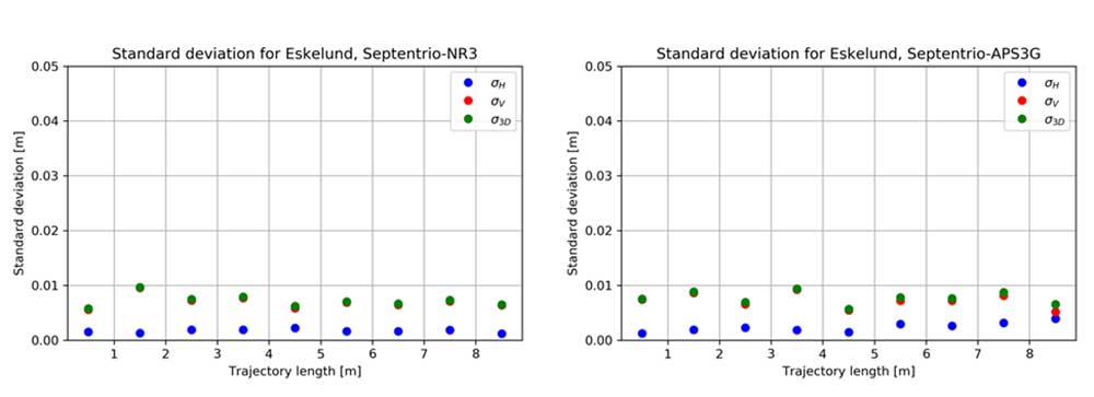
For each 1-meter section of track, the standard deviation of the differences with respect to the reference trajectory of the 10 repetitions was calculated. Results for the two survey-grade receivers are shown in the plots in Figure 3. All of the 3D standard deviations are better than 1 cm for both survey-grade receivers.
Figure 3. Kinematic test results are provided for the vertical (red), horizontal (blue) and 3D (green) positions. (Image: DTU Space)
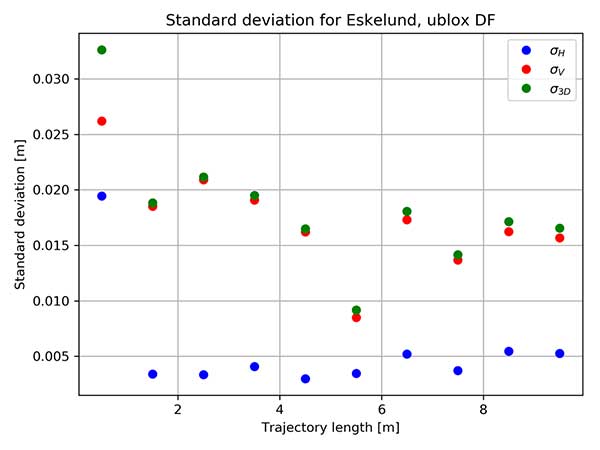
The non-survey-grade dual-frequency receiver also was mounted on the test bench, and the results of using this receiver are shown in the plot below. With this receiver, the 3D results are below 2.1 cm for all sections of the trajectory, except for the first meter, a deviation that may have been caused by issues with initialization of the test.
Binned standard deviation of 10 repetitions with GNSS receiver u-blox F9P dual frequency (DF). Results provided in meter. (Image: DTU Space)
These tests show that it is possible when using TAPAS to obtain position solutions at the cm-level in open areas in both static and kinematic mode.
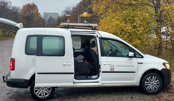
Performance test in dynamic mode. In November 2019, DTU Space carried out a performance test of TAPAS in dynamic mode, using a car with roof-mounted GNSS equipment. The car was driven within the TAPAS coverage area, passing through urban canyons, open streets and the harbor area. During the test, the car drove in normal Aarhus traffic, at speeds varying from zero at traffic lights up to 60 km/h on the wider roads leading into the city center.
Four different receivers were strapped in the car and connected to either a small patch antenna or a survey-grade antenna mounted on the roof. A survey-grade receiver was mounted on the roof.
Three different GNSS antennas mounted on the roof of the car used for dynamic testing. (Photo: DTU Space)
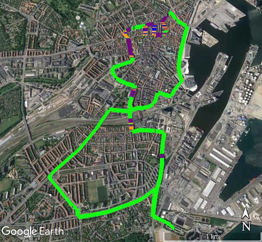
Data from the receiver was converted to KML files, which can be used with Google Earth to illustrate the quality of the positioning obtained during the drives through the city. The plot in Figure 4 shows the quality of the position solution. The best quality is obtained when the ambiguities are fixed, such as an RTK fixed solution at the cm level (green). The second-best quality is with ambiguities estimated to float values, such as an RTK float solution at the dm level (purple). Orange shows differential position solutions at the meter level when corrections for the carrier-phase data have not been obtained. Finally, a few positions were stand-alone GNSS solutions when no aiding from TAPAS was applied in the roving GNSS receiver (blue).
Figure 4. Quality of RTK positions obtained during one drive through the City of Aarhus. (Map data: Google, TerraMetrics)Photo:
The plot clearly shows, as expected, that the quality of the positions determined by the survey-grade receiver in the car is good most of the time. But it suffers in areas with narrow streets aligned with buildings or trees.
These results do not tell the actual uncertainty of the position solutions. But GNSS carrier-phase data collected with one of the receivers in the car during the drive will be post processed to serve as a reference trajectory. Upcoming analyses of the data will then reveal the uncertainty of the positions determined in real time as compared to the post-processed reference trajectory.
Test Conclusion. After the field tests, we conclude that the TAPAS testbed is able to provide correction data that makes it possible to perform GNSS-based positioning in real time in both static and dynamic mode with position uncertainties at the cm-level. Further, as we analyze the test data thoroughly, TAPAS will be able to set a tone for new research. For instance, the plot in Figure 4 provides a foundation for testing assistance procedures to gain better coverage in the most densely built areas. In this way, TAPAS will aid research into feasible infrastructure for the technologies of tomorrow, such as autonomous driving.
Outlook and Future Work
Because TAPAS is not commercial, it is possible, upon agreement with the SDFE, to make changes to the system to adapt to specific testing or development needs. Examples are removing data from some stations in the estimation of RTK correction data, installing an extra receiver in one or more stations using the antenna splitters, or making changes to the settings in data processing on the TAPAS server for shorter time intervals.
At DTU Space, plans for the testbed include further development of software for ionosphere and integrity monitoring. The station receivers can estimate total electron content (TEC) along the GNSS signal path in Earth’s atmosphere, as well as indices for ionospheric scintillation. DTU Space is researching using this output for an ionosphere monitoring service and to develop it into an integrity monitoring service for GNSS users.
Upcoming additions to the RTCM data format will support more advanced modeling of the effects of the ionosphere and troposphere, and this will allow for full benefit of the TAPAS SSR network corrections. Research on such models to be applied on the server side, as well as on the user side, will be carried out by DTU Space and tested with TAPAS as a contribution towards the integration, or hybridising, of PPP and RTK. This is also referred to as PPP-RTK positioning which is expected to be especially useful for mass market applications such as autonomous driving. When implemented in TAPAS, such solution may effectively increase the number of simultaneous users as well as use-cases for TAPAS.
TAPAS provides many opportunities for testing precision or high-accuracy applications, such as autonomous vehicles, vessels, drones and robots; location-based services requiring high accuracy on various digital platforms; and solutions for a more digitized and intelligent city environment through smart-city and green mobility initiatives.
TAPAS is prepared for the implementation of the coming 5G technologies, and station intercommunication capabilities enable testing of internet of things (IoT) technologies where precision positioning is part of the development. The testbed also provides an excellent environment for validation of new services such as the Galileo High Accuracy Service (HAS). Another area in which TAPAS can play an important role is verification and validation of future 5G-based positioning services.
The TAPAS testbed was developed with close cooperation between DTU Space and SDFE. SDFE contributors include Kristian Keller, Casper Jepsen, Henrik Olsen, Martin Skjold Grøntved, Brigitte Rosenkranz, Maria Rask Mylius and Søren Fauerholm Christensen. DTU Space contributers include Ole Bjerregaard Hansen, Finn Bo Madsen, Lars Stenseng, Daniel Haugård Olesen, Stefan Emil Steffensen, Thor Heine Snedker, Per Knudsen and Niels Andersen.
Manufacturers
The GNSS receivers at the TAPAS stations are Septentrio PolaRx5S, and the antennas are Leica AR20. For field testing, a Septentrio Altus NR3 receiver, a Septentrio Altus APS3G receiver and a u-blox ZED F9P dual-frequency receiver were used. The TAPAS station cabinets were assembled and mounted by Nordtec-Optomatic A/S. The TAPAS testbed software solution is based on the GNSMART 2 software package from Geo++ GmbH. Data analyses and processing has been carried out using the Septentrio SBF Analyser and SBF Converter, the RTKlib and the Bernese GNSS software.
Anna B. O. Jensen is senior advisor and team lead of the GNSS group at DTU Space in Denmark. She is also a part-time professor at KTH Royal Institute of Technology in Sweden.
Per Lundahl Thomsen is a chief consultant at DTU Space. He has many years of experience with management of space technology projects and is project manager for the TAPAS testbed.
Søren Skaarup Larsen is a Ph.D. student at DTU Space. Along with his GNSS studies, he runs the RTK-part of the TAPAS testbed.
Qorvo, a provider of RF solutions, is acquiring Decawave, as well as Custom MMIC. Financial details have not been disclosed.
“This acquisition is by far the biggest in the indoor location industry,” according to Bruce Krulwich, founder of Grizzly Analytics. “While the price is not disclosed, I and others have estimated it at $400-500 million.”
“Apple is using their own UWB chips in upcoming iPhones, but their own chips are too big and use too much power to be used in smartwatches or other small devices,” Krulwich said. “Decawave’s chips will enable Qurvo to sell compatible UWB chips to a much wider range of markets.Apple’s use of UWB in iPhones is the tipping point for UWB. With Apple’s stamp of approval, UWB will be incorporated into a wide range of location-aware electronics, including robots, drones, wearables, smartwatches and more.”
“The biggest implications for this acquisition are not only in the RTLS market, but also in the areas of internet of things, wearables and location-aware electronics,” Krulwich said. “UWB is being used in next-generation products like drones by Intel, robots by iRobot, and autonomous vehicle movement by Segway.”
Bob Bruggeworth, president and chief executive officer of Qorvo, said in a third-quarter financial release that the company was “looking forward to welcoming two industry-leading teams, Decawave and Custom MMIC, to the Qorvo family, expanding our technology portfolio and product offerings.”
Decawave is an Irish fabless semiconductor company specializing in precise location and connectivity applications. The acquisition will advance market penetration of IR-UWB and enable broad global adoption of the technology.
Decawave was founded in Dublin in 2007 by current CEO Ciaran Connell and CTO Michael McLaughlin. The co-founders had a vision that the new IR-UWB technology, based on a nascent IEEE standard, could deliver ultra-accurate location in a way that would revolutionize people’s lives like GPS did in the 1990s.
Twelve years later, IR-UWB is on the verge of becoming the next essential component technology, like GPS, Wi-Fi and Bluetooth before it. Already shipping in millions of smartphones and cars, and across more than 40 other verticals, IR-UWB is enabling accurate indoor location services, secure communications, context aware user interfaces and advanced analytics.
“We are thrilled to announce the acquisition of Decawave by Qorvo,” said co-founder and CEO Ciaran Connell. “We have created an incredibly unique technology, but we understand that to embrace the opportunity in front of us, we will need greater resources to execute at scale, accelerate our innovation and product launches and to continue to support our growing customer base with the same level of service.
“Joining forces with Qorvo’s leading expertise in RF technology, their experience in serving very high-volume markets like Mobile but also the thousands of customers in Industrial and Enterprise, is, for Decawave, a perfect combination to scale and further accelerate the adoption of IR-UWB.”
Eric Creviston, President of Qorvo Mobile Products, said, “We’re very pleased to welcome the Decawave team, which we believe will enhance Qorvo’s product and technology leadership while expanding new opportunities in mobile, automotive and IoT. We look forward to building on the groundbreaking work that Decawave has done and helping to drive new applications and businesses using their unique UWB capability.”
Decawave co-founder Michael McLaughlin added, “From proving a new technology, to building new markets and to today joining a Tier 1 semiconductor company, the past 12 years have been a challenging and fantastic journey.
“None of this would have been possible without the dedication and passion of Decawave employees as well as the constant support from our lead investor Atlantic Bridge, Act Venture Capital, Summit Bridge, Enterprise Ireland and our business angels. To all others who accompanied us on this journey we also say a sincere and profound thank you and we look forward to the next chapter for IR-UWB.”
In the coming months and years Decawave and Qorvo will:
Continue to contribute to the IEEE, Car Connectivity Consortium, FiRa and UWB alliance to define next-generation PHYs and protocols, ensuring interoperability across applications and fueling IR-UWB adoption,
Accelerate the roadmap of ICs and modules, leveraging their respective R&D strengths and product portfolio to bring even more IR-UWB solutions to the market,
Pursue existing partnerships and investments in enablement to offer flexible and easy to integrate IR-UWB solutions to our customers.
Sapcorda Services GmbH has released its SAPA (Safe And Precise Augmentation) Premium GNSS positioning service.
The SAPA service enables mass-market GNSS devices to operate with increased accuracy and reliability across Europe and the continental United States. The service’s technology unlocks advanced performance with instantaneous sub-decimeter position accuracy for devices used in all market applications.
SAPA is delivered using the open industry-recognized SPARTN format, which allows efficiently delivery of the correction data via internet and satellite broadcast. “When using our service, users across Europe and the United States can experience homogeneous, gap-free, advanced positioning performance with any GNSS hardware designed for high precision positioning,” CTO Rodrigo Leandro said.
The SAPA service is tailored for mass-market applications including innovative mobility solutions, IoT applications, and traditional markets such as maritime.
SAPA was designed from ground up to support safety-critical applications such as autonomous driving.
SPARTN (Safe Position Augmentation for Real-Time Navigation) is a high-accuracy, open- and free-to-use GNSS format tailored for broadcast distribution in mass-market applications.
Sapcorda Services GmbH is a GNSS service provider focusing on the emerging high-precision GNSS mass markets. The company has designed its technology and service offering to serve high volume automotive, industrial and consumer markets.
What are the key technical criteria in matching GNSS receivers and antennas from the same or different manufacturers? For what uses does it matter most?
John Fisher. (Photo: Orolia)
“For fixed-pattern antennas, it’s fairly simple: RF + DC to power the antenna. Most vendors are compatible. The challenge is more for controlled radiation pattern antennas (CRPA). Power requirements vary greatly, and performance can be improved with a two-way data exchange between the CRPA and receiver, but there is no industry standard yet for this interface. An example: tilt angles from the receiver’s IMU can greatly aid beam pointing.” John Fischer Orolia
Ellen Hall
“Antenna selection is exceptionally critical for our military and high-precision users. The platform and environment are the primary drivers of these antenna requirements. In general, SWaP (size, weight and power) is at the forefront of all criteria. As operational plans are developed, requirements for a single or multi-element array, element gain, and noise figure must be considered.” Ellen Hall Spirent Federal Systems
Members of the EAB
Tony Agresta Nearmap
Miguel Amor Hexagon Positioning Intelligence
Thibault Bonnevie SBG Systems
Alison Brown NAVSYS Corporation
Ismael Colomina GeoNumerics
Clem Driscoll C.J. Driscoll & Associates
John Fischer Orolia
Ellen Hall Spirent Federal Systems
Jules McNeff Overlook Systems Technologies, Inc.
Terry Moore University of Nottingham
Bradford W. Parkinson Stanford Center for Position, Navigation and Time
A proposed FAA rule — open for public comment until March 2 — would require drones over 0.55 pounds to electronically transmit their location and ID.
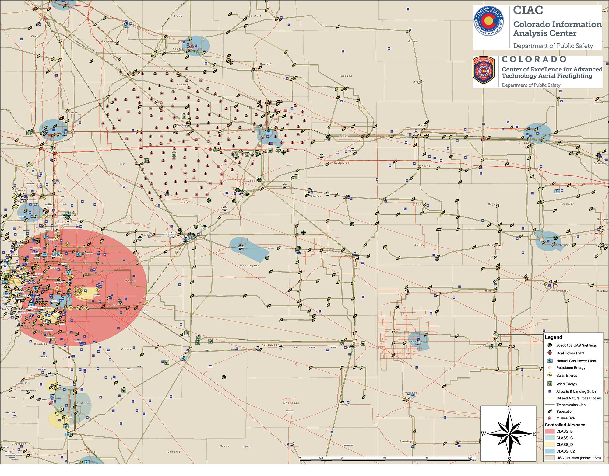
Northeastern Colorado was visited with a mystery in late December and January. Residents began seeing drones from 7 to 10 p.m. each night, moving in groups as large as 30, and flying in a grid pattern. The drones stayed about 200 feet to 300 feet in the air and flew steadily in squares of about 25 miles, at speeds estimated at 25–40 mph.
Reports were so numerous that a multi-agency task force was formed to investigate, including 10–15 law enforcement agencies as well as the FBI and Federal Aviation Administration (FAA). The drones were reported to measure six feet across and sound like a small jet engine. “These are not drones that people in our county can just buy,” said Washington County Sheriff Jon Stivers.
Numerous government agencies and companies denied the drones were theirs, including the U.S. Air Force, NOAA, NORAD, the FAA, and large drone developers Google, Amazon and Uber.
The Colorado Division of Fire Prevention and Control (DFPC) flew the state’s Multi-Mission Aircraft in an area where drones had been reported during two January missions.
This DFPC map, obtained by FOX31 TV, shows possible locations of drone sightings along with power plants, pipelines and missile sites. (Map: Colorado Division of Fire Prevention and Control)
Some suspect the drones were part of a secretive Air Force counter-drone program to protect nuclear missile silos. Another theory was a hunt for a missing nuclear warhead from one of the many intercontinental ballistic missile sites that dot the prairies of Wyoming, Colorado and Nebraska.
A group of Wichita, Kansas, drone enthusiasts also came forward, saying they had flown groups of drones in the area — but not to the same scale.
In an interview at January’s World Economic Forum in Davos, Switzerland, Transportation Secretary Elaine Chao told Yahoo Finance, “We don’t know who they belong to, we don’t know who’s operating them, to this day we do not.” Her department oversees the FAA, which issues Part 107 waivers to drone operators, allowing them to fly at night or out of line of sight of the operator. The waivers (thousands have been issued) lack enough specifics to narrow down who might be responsible for mystery drones.
A proposed FAA rule — open for public comment until March 2 — would require drones over 0.55 pounds to electronically transmit their location and ID, giving agencies access to information on drones in flight.
The new remote ID requirement would help with the creation of the Unmanned Aircraft System Traffic Management System, a project between the FAA, NASA and other agencies to “ultimately identify services, roles and responsibilities, information architecture, data exchange protocols, software functions, infrastructure, and performance requirements for enabling the management of low-altitude uncontrolled drone operations,” according to the FAA.
As of press time, no one has come forward to claim ownership of the drones. The public is encouraged to submit reports. As The X-Files’ Fox Mulder might say, “Watch the skies.”
At ION GNSS+ in September, I met with Nunzio Gambale and Paul Benshoeff of Locata. They were excited to share their news about the timing tests conducted at White Sands Missile Range by the U.S. Air Force’s 746th Test Squadron.
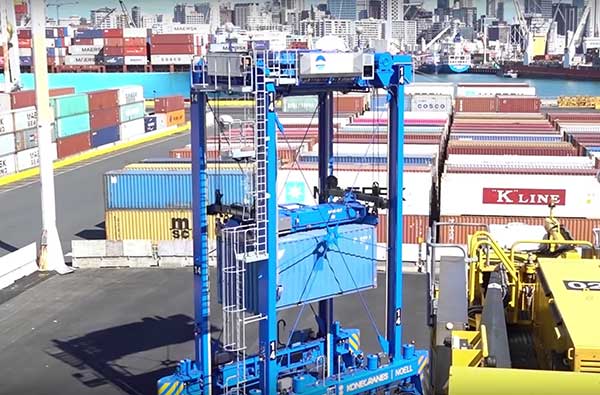
In the January issue, we share the results of the tests. The two also showed me and Matteo Luccio, our contributing editor, a YouTube video highlighting another Locata project: guiding 100-ton robots around the Ports of Auckland, New Zealand.
The robots are straddle carriers, giant mechanisms that are usually driven by a human. The carriers move and sort the shipping containers as they arrive from ships and leave via truck or train.
In the new setup, Locata has made possible the elimination of the human element with nanosecond-precision tracking.
Tom Scott, a former Sky One television host and now host of a series of YouTube shows, highlighted the robotic system in April 2019 on his “Amazing Places” channel.
Screenshot: Tom Scott video
Compared to manned straddle carriers, the automated straddle carriers (A-STRADs) are able to stack the containers closer, higher and work more steadily, increasing the capacity of the limited land space at the port. The A-STRADs can stack containers with the accuracy of a few centimeters.
The automated system also allows stack shuffling, so that wear and tear on the asphalt is spread more evenly and requires fewer repairs.
The Locata local positioning system uses synchronized transmitters installed around the port, with two antennas on each straddle carrier using the lightspeed delay from each transmitter to find exact position. “They don’t just look at the timing signal itself, they track the phase of each transmitter’s carrier signal,” Scott explained.
Highly accurate, UK city-wide 3D models are now available to view and download from Bluesky’s online Mapshop.
The geographically accurate, photo-realistic MetroVista mesh models are available in a variety of formats ready for use in 3D GIS, CAD and other modelling software as well as visualisation, gaming and Virtual Reality workflows.
Captured using Leica’s large-format imagery and lidar hybrid airborne sensor and generated in Skyline’s PhotoMesh software, the Bluesky MetroVista datasets of major UK cities are available online offering a compelling alternative to traditional photogrammetrically produced models.
Now in America. In December, Bluesky launched its 3D data capture programme in the United States. The MetroVista product suite allows high-resolution imagery, both vertical and oblique, to be captured simultaneously with high-accuracy, wide-scale 3D data using an advanced Leica camera, the CityMapper. Specifically designed for 3D city modeling and urban mapping, the system includes a traditional vertical camera as well as survey-grade oblique cameras.
The CityMapper also includes high-performance lidar technology to accurately collect elevation data — even in shadows that are common in urban environments and can make photo-based collection difficult.
“Since launching in the UK the MetroVista product range has received enormous offline interest from sectors such as infrastructure and building development, risk assessment, telecommunications and environmental mapping,” said Rachel Tidmarsh, managing director of Bluesky. “By making the data easy to access and consume via our online Mapshop, we hope to increase the take up from traditional users of 3D models and encourage applications such as smart city management, autonomous vehicle testing, virtual reality experiences and gaming.”
Two seasons in the UK
Bluesky has been capturing MetroVista data in the UK for two flying seasons. Visitors to Bluesky’s Mapshop will initially be able to select an area and download MetroVista mesh models of London, Birmingham and Cambridge with other UK and U.S. cities coming online in the future.
Data can be supplied in a variety of proprietary and open source formats including OBJ, FBX, I3s and 3DML for use in Skyline’s TerraExplorer product suite.
The Bluesky Mapshop also offers complete nationwide coverage of aerial photography from multiple epochs, 3D models, lidar data, thermal mapping and Bluesky’s National Tree Map. Blueskymapshop.com is easy to use and purchasing of data is simple, straightforward and secure. Account options are also available and data can be purchased with a range of easy to understand licence options, including the option of a Sub Contractor Licence.
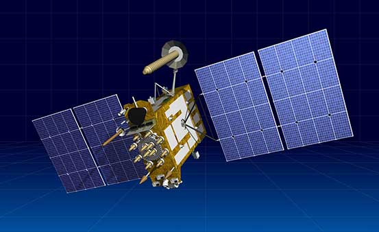
Artist’s rendering of a Glonass-K satellite. (Image: ISS-Reshetnev)
ISS-Reshetnev Company — the primary GLONASS contractor — has a backlog of orders for navigation satellites up to 2025, according to General Director Nikolay Testoyedov.
Testoyedov discussed GLONASS production on Dec. 30, 2019, at a meeting hosted by ISS-Reshetnev Company for Russia’s Science and Technical Council.
“Within the Federal Target Program, GLONASS ISS-Reshetnev Company is tasked with the production of 27 navigation satellites,” Testoyedov said. “Taking all things together, we plan to double the number of satellites launched in 2020 compared to 2019.”
The orders require production at full capacity at the company’s facilities. At any given time, about 50 satellites are in varying stages of production, including 12 ground spares. Some of them are slated for launch in 2020.
In 2019 eight satellites designed and built by the company were launched into various orbits. As of today, 104 ISS-Reshetnev-made satellites are in space, or two-thirds of Russia’s entire orbital fleet of satellites. ISS-Reshetnev also successfully completed several projects for the manufacture of satellite onboard systems and instruments, including the international ExoMars-2020 program slated to launch this year.
A joint team of experts representing ISS-Reshetnev Company and the operating organization successfully completed all procedures moving the Glonass-M satellite to its proper orbital position, and switched on its main instruments. To this date, all the required data has been received from the satellite, which allowed it to be commissioned into service.
The new Glonass-M replaced a retired satellite of the GLONASS constellation that had surpassed its designed life expectancy by seven years.
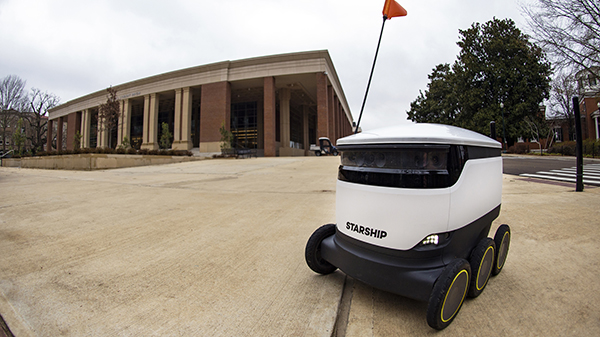
Photo: Christian Johnson/University of Mississippi
As University of Mississippi (UM) students resume classes for the spring semester, they are sharing the campus’ sidewalks with a fleet of robots that can deliver meals at the push of a button.
Starship Technologies has launched robot food delivery services at the university, the first in the Southeastern Conference to have autonomous delivery robots.
Beginning Jan. 22, Ole Miss students, faculty and staff can access the Starship Deliveries app (iOS and Android) to order food and drinks to be delivered anywhere on campus, within minutes from any of the 30 robots serving UM. The service will work in conjunction with student meal plans.
“Ole Miss Dining is focused on the continued utilization of advanced technology to enrich the student, faculty and staff dining experience,” said Chip Burr, resident district manager of Ole Miss Dining Services. “We are excited about the expansion of our mobile ordering operation and the new opportunities this partnership creates.”
The robots use a combination of sophisticated machine learning, artificial intelligence and sensors to travel on sidewalks and navigate around obstacles. The computer vision-based navigation helps the robots to map their environment to the nearest inch. They can cross streets, climb curbs, travel at night and operate in both rain and snow.
A team of humans also can monitor their progress remotely and take control if needed.
By making food and drink more accessible, the Starship robots save time and reduce stress, aiming to make the busy lives of the Ole Miss community a little easier, Burr said.
Items can be ordered from Starbucks, Chick-fil-A, McAlister’s, Panda Express, Which Wich, Qdoba, Einstein Bros. Bagels, Raising Cane’s, Steak ‘n Shake, Freshii, Papa John’s and Sambazon. After choosing their items, users select their location by dropping a pin on the campus map where they want their food delivered.
The app allows users to watch the robot’s journey in real time through an interactive map. Once the robot arrives, the user will receive an alert and can meet the robot and unlock it through the app.
The delivery usually takes just minutes, depending on the menu items ordered and the distance the robot must travel. The robots can carry up to 20 pounds.
Starship Technologies operates commercially on a daily basis around the world. Its robots have traveled more than 350,000 miles and completed 100,000 autonomous deliveries.
“We’re honored to be able to help make lives a little bit easier for Rebels across the Ole Miss campus by offering the world’s leading autonomous delivery service,” said Ryan Tuohy, senior vice president of business development at Starship. “Whether it’s getting breakfast delivered in the morning or having a late-night snack, our robots are here to serve students, faculty and staff at all times of the day.”