Hexagon AB, a global leader in sensor, software and autonomous solutions, introduced its Smart Autonomous Mobility solutions portfolio today at CES 2020, bringing together all the necessary sensors, software and services to make autonomous driving possible.
CES 2020, the massive annual consumer electronics show, is taking place Jan. 7-10 in Las Vegas. Hexagon’s Smart Autonomous Mobility solutions portfolio will be demonstrated in Hexagon’s pavilion CP-15.
Hexagon said it is on a mission to enable all customers to accelerate and deploy a bold autonomous mobility vision — from research and development to advanced machine learning and simulation, to full integration and production into industry ecosystems.
“Through our Smart Autonomous Mobility solutions portfolio, Hexagon is empowering an autonomous future that can transform ecosystems, protecting millions of lives and dramatically lowering carbon emissions,” said Ola Rollén, Hexagon president and CEO. “We are committed to providing complete technology solutions that enable our customers to build, test and put fully autonomous fleets to work safely.”
The Smart Autonomous Mobility portfolio includes three solution sets: Enable, Accelerate and Deploy.
Enable. Hexagon enables customers to fast-track R&D with hardware, software, and services to quickly enable autonomous driving systems across a variety of vehicle platforms and applications. From providing a turn-key automated driving research vehicle platform for field testing, integrating a customisable and assured positioning engine with reliable correction services, and offering baseline simulation tools and high-accuracy ground truth, Hexagon has already enabled thousands of customers worldwide with these technologies.
Accelerate. Hexagon enables customers to create Smart Digital Realities — seamless workflows between real-world and simulated environments. To drive even 20% better than a human driver requires 11 billion miles of validation, which is equivalent to 500 years of non-stop driving in the real world with a fleet of 100 cars.
With machine learning, simulation and testing for entire system performance and engineering and integration services, and high-definition digital reality capture, visualization and on-demand feature extraction, Hexagon allows customers to optimise, verify and validate the necessary billions of miles of driving required to safely deploy autonomous vehicles to the road.
Deploy. Hexagon allows customers to quickly scale from prototype and R&D phases to production for any autonomous application. The automotive-grade hardware solutions, autonomy software technologies, and functionally safe positioning solutions and services available in Hexagon’s Smart Autonomous Mobility portfolio are ready to deploy at scale for:
Mass production of passenger vehicles
Neighborhood electric vehicles (NEV)
Tractor trailers (class 8)
Off-road vehicles for mining, agriculture and defense
Technology includes vehicle-grade computing platform solution, high-dynamic range camera and ADS synchronization controller
DeepRoute, an international self-driving startup and CES 2020 Innovation Award Honoree, will be debuting three innovative technologies at CES 2020 including a vehicle-grade computing platform solution, DeepRoute-Tite, high-dynamic-range camera and ADS synchronization controller.
CES 2020, the massive annual consumer electronics show, is taking place Jan. 7-10 in Las Vegas. The company will be located at Booth no. 25647 at South Hall 2 LVCC throughout the show.
“It is an honor to be joining international innovators at CES 2020,” said Shuang Gao, Chief Operating Officer of DeepRoute. “We’ve worked hard over the last year to perfect our technologies and reinforce the safety of autonomous vehicles. We are excited to unveil the fruits of our team’s hard work, creativity and talent to the world at the prestigious and highly anticipated global technology show.”
DeepRoute-Tite, the company’s computing platform solution that migrates the algorithm required for L4 level autonomous driving to the vehicle-level computing platform, Nvidia Xavier, significantly reducing the cost, size and power consumption down to 45 watts. DeepRoute’s computing platform solution uses Nvidia’s vehicle-specific computing platform Xavier to process L4 level autonomous driving modules such as perception, prediction, decision-making, planning and control, along with navigation.
Along with the debut of the computing platform, DeepRoute will be launching its first-generation vehicle camera, DeepRoute-Vision. The vehicle camera has a higher dynamic range than other products on the market, allowing optimal performance even under bright sunlight or from within a dark tunnel. Designed to handle LED bulb flicker, the camera can also accurately capture information displayed on LED screens. The vehicle camera will be on display and demonstrated by DeepRoute representatives at the show.
DeepRoute also plans to unveil its second-generation ADS Synchronization Controller, DeepRoute-Syntric. The ADS controller can synchronize information from different types of sensors, enabling the perception algorithm to process sensor data aligned in the same standard. In the event that the sensors malfunction, the ADS controller can take control of the vehicle and perform emergency tasks such as braking.
The company recently announced the availability of DeepRoute Sense, their driving sensing solution technology which will be on display at the show alongside their Level 4 full-stack self-driving technology using a demo vehicle with an independently designed roof box equipped with 8 vehicle cameras, 3 lidars, GNSS and a series of other sensors.
At any given moment, more than 5,000 airplanes are flying over the United States. In a single year, nearly 778 million passengers will take to the skies — more than twice the population of the U.S., and the number increases each year. Aviation is the safest form of transportation. It is 100 times safer than driving. For every 100 traffic deaths, only one aviation related fatality occurs; and the Federal Aviation Administration (FAA) is working hard to make aviation even safer.
Safety is the FAA’s primary focus. The FAA Strategic Plan FY 2019– 2022 states its mission is to provide the safest, most efficient aviation system in the world. To achieve this goal, the FAA is implementing several initiatives. The technical aspects of these efforts fall under a framework called NextGen designed to modernize the nation’s air traffic control system. NextGen began in 2003 in the VISION 100 – Century of Aviation Reauthorization Act. At its core, NextGen is a geospatial framework with satellite navigation as its backbone.
The Geospatial Data Act (GDA) became law when President Trump signed the FAA Reauthorization on Oct. 5, 2018. You might have wondered how the GDA came to be included in the bill. It makes sense in the context of technology advancements towards a smart transportation network, specifically in aviation.
The smart transportation concept integrates all forms of transportation to provide economic and environmental benefits as well as increase safety and reduce wait times and congestion. A large part of smart transportation is based on geographic information technology. The aviation component of this smart transportation initiative falls within the FAA’s authority under the overarching framework named NextGen.
NextGen is an integrated concept improving the efficiency and safety of flight operations both on the ground and in the air. The use of geospatial technology enables precision time-management for controlling air traffic. The system allows each airplane to digitally coordinate with other aircraft in the area, taking into account such things as terrain and other known hazards to safely reroute air traffic as necessary. The FAA refers to this as trajectory-based operations. Those with a knowledge of GIS will recognize it as four dimensional: it calculates direction, speed, distance and time relative to position in x-y-z, and coordinates that information with other known data. Additionally, the system uses historical flight data and predictive analytics to maximize airspace for routing air traffic such as what is experienced during the holidays.
NextGen also uses a system called Optimal Profile Descents (OPD), which allows an airplane to trim its engines and descend along a glide slope from flight level into the airport. The point at which a plane begins its descent is a geospatial calculation to determine the precise point in space for the airplane based upon its altitude, weight, glide slope and distance to the airport. The benefits of OPD are reduced engine noise, fuel savings, less carbon emissions and a positive economic impact. NextGen is an across-the-board win for the airline industry, airline passengers, the economy and the environment.
According to an interview with Michael Whitaker, former deputy administrator of the FAA who was the Chief NextGen Officer, NextGen revolutionizes aviation by enabling digital data communication. It replaces radar-based navigation and tracking with satellite-based air traffic control. The cornerstone of NextGen is the Automated Dependent Surveillance Broadcast (ADS-B) system.
ADS-B is an aviator’s version of Waze, but with a lot more information. ADS-B(out) broadcasts an airplane’s Flight ID, ICAO Code, speed and location in three-dimensional space to air traffic controllers and to everyone who is equipped with ADS-B(in). The combination of ADS-B(out) and ADS-B(in) greatly increases situational awareness for aviators. On Jan. 1, 2020, all airplanes operating in controlled airspace needed to have ADS-B(out) installed. ADS-B transforms the entire National Airspace System into a satellite-based geospatial network. It integrates multiple sources of real-time data, such as weather, pilot reports, aircraft positions, 3D airspace information, and other sources of data, which can be overlaid on top of various basemaps and terrain elevation models, allowing pilots to make more informed and safer decisions.
Switching to ADS-B opens up more capacity in already crowded skies by decreasing the required vertical and horizontal separation distances between aircraft. At Hartsfield-Jackson International Airport, the busiest airport in the world, changing to performance-based operations allowed 8 to 12 more departures per hour; and in Memphis International Airport, one of the busiest airports for cargo operations, arrivals increased by 20%.
Rune Duke, senior director of government affairs, Airspace, Air Traffic and Aviation Security for the Aircraft Owners and Pilots Association (AOPA), said that ADS-B will allow much faster update rates for air traffic controllers on the order of once every second, compared to legacy radar systems that report positions every 8 to 12 seconds. For an airplane traveling at 350 knots, that is about 1 mile. A lot can change in a mile in densely packed airspace.
If you are reading this because of your love of maps and aviation, then I highly recommend the FlightAware and ForeFlight smartphone apps. FlightAware turns the phone into an ADS-B(in) receiver showing the location and flightpath of each aircraft in the immediate area on a basemap. I sit on my back deck and watch airplanes coming and going because I live under the flightpaths for Dulles International Airport, Reagan International Airport, Leesburg Executive Airport, the Montgomery County Airpark and the TERPZ waypoint. On occasion I see helicopters flying to Camp David because I am under that flight path as well.
So, I get to see a variety of aircraft. You can select the airplane icon to see information such as aircraft type, airline, Flight ID, departing and arrival airports, altitude, and groundspeed. Even more information is available by selecting the pop-up window. This is ADS-B information. ForeFlight, on the other hand, is a pilot’s flight bag on a tablet.
In the future, ADS-B will integrate Aircraft Hazardous Areas (AHA): temporary no-fly zones due to commercial space launches. Because of ADS-B, planes will automatically reroute around the AHA, and when the AHA expires, airplanes will be routed back through the area.
ADS-B supports evolving technologies such as remote towers, another significant change to air traffic control. Remote towers allow air traffic controllers to be at a location other than the actual airfield. Remote towers use a suite of sensors mounted at the airfield, including high-definition video, thermal and night vision that can be combined with the digital information provided by ADS-B, all of which is displayed on widescreen panels in a room duplicating the experience of being at the airport and directing aircraft. This allows smaller airports that cannot afford the huge expense of building and staffing an air traffic control tower to be part of a remote tower network. One remote tower center will be able to support several airfields. Leesburg Executive Airpark recently finished successful testing of one of the first remote tower operations in the United States.
“Over the next 10 years, we are going to see logistics and transportation open up, from being limited by currently rigid road infrastructure to operating on fully flexible and responsive aerial transportation networks,” said Patrick Watson, director of business development for Animal Dynamics.
The envisioned Platform Unmanned Cargo Aircraft. (Photo: PUCA)
ADS-B will also support the integration of unmanned aerial systems (UAS) into the airspace, specifically unmanned cargo aircraft (UCA). In the not too distant future, carrier air fleets without pilots or aircrew will be taking to the skies. UCAs do not require crews, so there will be no need for water, toilets, sewage containment, kitchens or a cockpit (in the traditional sense). Taking those out will allow for more space in the plane to carry cargo and fuel. Plus, without crews on board, there will be no time restrictions on crew hours — planes will be able stay aloft longer and travel further. ADS-B greatly enables the success of this technology.
Septentrio’s GNSS devices are being used for high-accuracy positioning solutions by two companies.
Compact multi-frequency GPS/GNSS receiver module provides robust centimeter-level positioning for advanced driver assistance systems (ADAS) provided by NXP.
Septentrio and Analog Devices collaborate on high-performance GNSS/INS solutions.
Image: Sepentrio
NXP V2X Integration
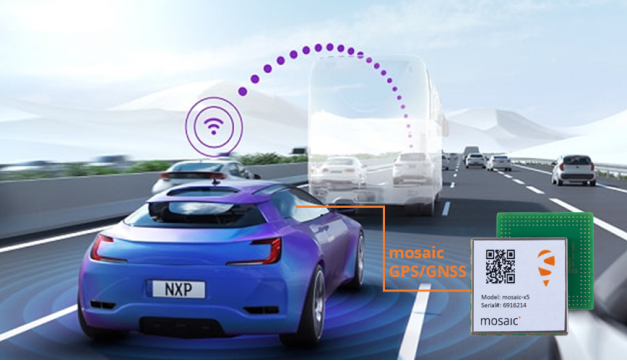
NXP, a leader in communication technology for embedded applications, is integrating Septentrio GNSS technology into its V2X (vehicle-to-everything) reference design and development boards.
Septentrio, a leading high-accuracy GNSS positioning company, is providing to NXP its mosaic module. Mosaic is a multi-frequency, multi-constellation GNSS receiver that delivers accurate and reliable global localization even in harsh environments.
V2X technology enables cars to communicate with infrastructure as well as other vehicles, making driving safer and more efficient. It enables cars to “see” what’s around the corner or through the dense urban environment warning the driver about road works, traffic congestion and emergency vehicles.
Precise GNSS-assisted localization combined with V2X communication enables a wide array of ADAS functionality such as automatic braking if slowing traffic is detected ahead or truck platooning.
Septentrio’s mosaic is a compact high-accuracy GNSS receiver module which is integrated into NXP’s V2X development boards. True multi-frequency multi-constellation technology gives mosaic access to every possible signal from all available GNSS constellations including the U.S. GPS, European Galileo, Russian GLONASS, Chinese BeiDou and Japanese QZSS satellites.
Septentrio’s advanced, field-proven algorithms exploit this signal diversity to deliver maximum positioning availability even in difficult environments such as under foliage or in urban areas.
“Reliable lane-accurate positioning is vital for many road-safety applications of V2X, such as queue and emergency stop warnings or blind spot warning,” said Andrew Turley, NXP’s senior director of innovation and V2X business development. “Septentrio’s unique easy-to-integrate GNSS module provides field-proven, reliable and robust positioning. Integration of mosaic into our reference design gives our customers a direct solution for developing these and other advanced V2X services.”
”We are excited that NXP selected our GNSS solution for their V2X reference design,” said Jan Van Hees, business development director at Septentrio. “NXP is a world-leader in complete solutions for V2X communications for active safety systems and intelligent transport system (ITS) management. Working with NXP gives us an excellent opportunity to bring the best of V2X and reliable GNSS to our customers.”
Inside a car GPS signals can become “jammed” by nearby electronics or illegal devices called “jammers” which are used by some drivers to avoid road tolling. mosaic uses jamming-resistant signal processing making it robust against interference. Its design is centered around continuous, reliable high-accuracy positioning making mosaic suitable for safety-critical applications such as ADAS and autonomous navigation.
Consumer Electronics Show. The Septentrio mosaic GNSS module will be showcased at CES in Las Vegas, January 7-10. Visitors are welcome to see mosaic and talk to Septentrio GPS experts about V2X, ADAS, INS and other automotive positioning solutions in booth 1135 at the Paradise West Center. A personal meeting can be booked in the Septentrio Suite at the Westgate Las Vegas Resort & Casino.
Combining with Analog Devices on INS
In December, Septentrio announced a collaboration with Analog Devices. The two companies are combining Analog Devices’ high-quality inertial measurement units (IMUs) with Septentrio’s multi-frequency, multi-constellation GNSS receivers.
The resulting high-performance GNSS/inertial navigation systems (GNSS/INS) deliver centimeter-accurate positioning together with 3D orientation (heading, pitch and roll), suitable for applications such as automotive ADAS and industrial automation.
“We are excited to work with Septentrio,” said Tony Zarola, general manager of inertial sensors, Analog Devices. ”Septentrio’s GNSS technology provides a unique combination of accuracy and robustness which is aligned well with the capabilities of our sensors. The company’s deep know-how of GNSS and focus on providing reliable solutions even in harsh environments complements Analog Devices’ focus to solve the toughest engineering challenges for our customers.”
“ADI’s high-end industrial IMU systems are a reference in the industry and we are very pleased to be working together with them,” said Danilo Sabbatini, product manager at Septentrio. “Combining ADI’s IMU experience with our GNSS expertise enables creation of high-performance, easy-to-integrate systems that allow our customers to tackle demanding applications. As a result, customers can expect a faster go-to-market due to the interoperability between the GNSS and INS components.”
Septentrio will incorporate Analog Devices’ advanced industrial-grade IMUs into a selection of its GNSS/INS products. Working directly with Analog Devices allows Septentrio to provide faster and more efficient GNSS/INS integration solutions for high-volume customers. This collaboration promises a solid foundation for design and production of top-performance integrated positioning and inertial solutions, with first products available in spring 2020.
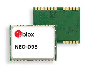
u-blox’s Bluetooth low-energy module features direction finding, bringing the benefits of high-precision positioning to indoor applications
U-blox, provider of positioning and wireless communication technologies, has announced the u-blox NINA-B4 Bluetooth low-energy module series. Based on Nordic Semiconductor’s recently announced nRF52833 chip, NINA-B4 enables a number of Bluetooth features including Bluetooth long range, Bluetooth mesh and Bluetooth direction finding.
The module is tailored to the needs of applications in the connected industry, smart homes, buildings and cities, asset tracking and eHealth.
The NINA-B4 offers a new direction-finding feature, a key component of the Bluetooth v5.1 specification that brings the benefits of high-precision positioning to indoor applications. It is the first u-blox module designed to act as both a transmitter and a receiver in angle of arrival (AoA) and angle of departure (AoD) direction finding and indoor positioning applications.
In AoA-based implementations, stationary beacons equipped with multi-antenna arrays determine the angle of arrival of signals emitted by a tracking device to pinpoint the tracker’s location with sub-meter-level accuracy. When AoD is used, the tracking device triangulates its position by calculating the angle of departure of signals from the stationary Bluetooth beacons’ multi-antenna arrays.
Mesh, long range, and extended temperature range
The u-blox NINA-B4 enables wireless mesh networks, which offer robust communication between large numbers of connected devices, extending the reach of messages by relaying them from node to node until they reach their destination. By simplifying the control of groups of devices, mesh networks are well suited for applications such as smart lighting systems in cities and buildings, which further benefit from the module’s enhanced operating temperature range (up to 105 °C).
Featuring Bluetooth long range, the NINA-B4 series can be deployed in harsh environments, for instance, to enable wirelessly connected and configurable equipment. Long range not only increases the distance that Bluetooth signals can travel in undisturbed environments, but also makes communications more robust and reliable in unfavorable ones, a common need in production plants or on factory floors.
The NINA-B4 series comes with u-blox u‑connect software, simplifying integration of Bluetooth into new and existing products by providing an easy-to-use interface to configure the connectivity required.
NINA-B4 has a powerful Arm Cortex-M4F MCU with an open CPU architecture, allowing customers to run their own applications on the module. Supporting Zigbee and Thread, the first members of the NINA-B4 family come with an internal PCB antenna, or alternatively with a U.FL connector for an external antenna of choice.
Samples of the NINA-B4 will be available in December.
How AI and machine learning algorithms redefine the way utility companies manage their infrastructure
By Jaro Uljanovs, Lead AI Developer and Data Scientist, Sharper Shape
Artificial intelligence (AI) boasts a wide range of potential applications, across nearly every industry imaginable — healthcare, automotive, retail, even fast food. But it’s the utility industry where AI and machine learning (ML) are beginning to demonstrate some of their most impactful effects on many aspects of the business. Power companies are increasingly leaning on AI to improve their electricity delivery and prevent potential wildfires, and AI is actually enhancing, rather than eliminating, human jobs.
From data collection and analysis to their presentation of actionable insights, AI and ML algorithms are quickly redefining how utility companies manage their electric infrastructure.
Consolidating and classifying data
Utility companies oversee massive infrastructure networks, comprising poles, conductors, substations and transmission and distribution lines that span thousands of miles. The vegetation surrounding this key infrastructure must also be monitored, as it presents a danger of fire or outage.
Taking a comprehensive snapshot of these assets means utilizing a variety of different sensors for network inspections. These sensors include lidar, color (RGB), hyperspectral and thermal imagery.
This allows the system to capture everything — from vegetation proximity, to infrastructure assets, to individual components (such as insulators on poles) and their operational integrity, to hot spots indicating potential fire risks.
That’s a lot of data to capture, catalog and process. And there are a lot of individual elements within that data — even in just one image — to pinpoint and classify, let alone do so accurately. Classifying billions of data points across all of those images is an impossibly time-consuming task to do manually.
Photo: shaunl/E+/Getty Images
AI and ML tools can accomplish that same work — scanning thousands of images collected across thousands of miles of utility infrastructure — in seconds. Lidar point cloud segmentation can detect conductors (quite a difficult component-type to segment) with an accuracy of over 90%, while hyperspectral image segmentation can identify vegetation species with an accuracy of up to 99%.
More than that, when paired with drone sensors, these algorithms can also improve the upfront collection of images and data. AI and ML tools help to adjust sensor positioning in real time, in the event a signal is lost or the drone veers slightly away from its inspection flight path.
By helping to readjust the sensors’ bearings while in flight, AI not only ensures more accurate data collection, but also that the flight doesn’t need to be done again or prematurely ended because of faulty data collection, saving time and money. AI pinpoints any faults in the sensors or the drone’s flight path while in the air, recalibrating as needed and identifying individual elements within the data as it comes through the sensor’s video feed.
Breaking down silos to create a holistic data approach
Key to all of this is eliminating the silos that tend to naturally build up between different data segments. In the utility inspection space, asset management, vegetation management, different sensors and so on all produce their own disparate, walled-off sets of data.
When data is kept siloed like this, it becomes unnecessarily difficult if not impossible for teams to derive companywide insights or conclusions from the information being collected. And what good is all that data if it can’t be used to check against itself and enhance other sets of data?
Good data management can’t exist in a piecemeal approach. It needs to be holistic, and AI provides the impetus to make that happen. AI provides a central resource for pooling all these data sources together, making it easier to cross-analyze for potential problems — like wildfire-prone vegetation or damaged components. When these issues are collected in one system, it becomes much easier to identify faults and resolve them — and do so far faster than it would be to manually sift through countless images of poles or vegetation maps.
And for all the stereotypical concerns about AI eliminating work for human beings, at utility companies AI actually enhances the role that people have to play in the network inspection process. Because the AI is what analyzes the data, it’s not something that is dependent on the potentially biased expertise of a professional human inspector, nor is it prone to fatigue and the anomalous results that can come from that. But at the same time, AI can’t do everything itself. It’s a tool for presenting clearer, more accurate and more actionable information for the people to then act on with their own judgment.
There’s a lot of easy-to-make assumptions, both good and bad, about AI. But at the end of the day, what AI really means for the utility industry is a more efficient and effective tool for providing the right information about a power company’s infrastructure — its transmission and distributions lines, its poles, and its nearby vegetation — into the hands of its key decision makers.
Hitec stated in a press release, “SUI’s experience in engineering and manufacturing small unmanned aircraft systems contributes perfectly with our expanding unmanned product platforms and progressive mapping and data acquisition solutions.”
Hitec Commercial Solutions continues to obtain integral assets which strengthen those products utilized for efficient surveying in agriculture, energy and gas, public safety, construction and first response services.
The acquisition agreement was closed Aug. 9 after approval by core members of the board of directors.
Hitec offers a variety of unmanned platforms, including the XENO FX, its proprietary fixed wing platform. The company also partners with Quantum Systems.
Founded in 2015, SUI provides technology in professional-use small unmanned aircraft systems (sUAS) with its Endurance and Endurance LT customized multirotor packages and ground controller system.
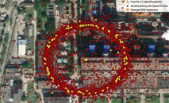
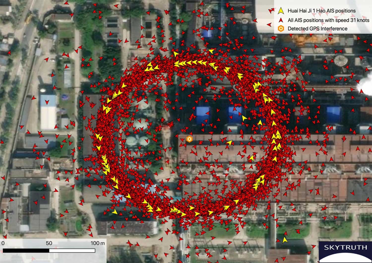
“GPS spoofing circles” have been discovered at 20 locations along the Chinese coast, according to the non-profit environmental group Skytruth. Of the locations observed, 16 were oil terminals; the others were corporate and government offices.
GPS spoofing in Shanghai that resulted in reported positions from ships, fitness trackers and other GPS enabled devices forming circles some distance from the shore was first observed by the non-profit C4ADS. Subsequently, Professor Todd Humphreys briefed the phenomena at an Institute of Navigation conference in September. The MIT Technology Review published an article about it in November.
This caught the interest of an analyst at the environmental non-profit Skytruth.
Evaluating a larger data set of ship AIS (Automatic Identification System) data, analyst Bjorn Bergman discovered at least 20 locations near the Chinese coast where similar spoofing had taken place in the last two years.
Sixteen of these “spoofing circle” locations were oil terminals. The most frequent occurrences by far were at the port of Dalian in northern China, close to the border with North Korea. Based upon the timing of the spoofing, imposition of sanctions on purchase of Iranian oil by the United States, and observations by others of Iranian oil being received by China, Bergman suggests that much of the spoofing is designed to help conceal these transactions.
Of the four locations not associated with oil terminals, three were government offices and one was the headquarters of the Qingjian industrial group, a huge engineering and construction conglomerate. These infrequent and irregular events may be related to visits by important government officials. A C4ADS report earlier this year demonstrated Russia uses GPS spoofing extensively for government VIP protection.
Bergman suggests that the actual spoofing device is located at the center of each of the rings formed by false GPS reports. He has also observed that not all AIS/GPS receivers in the impacted area are affected, the spoofing circles tend to be about 200 meters in diameter, many false vessel positions orbit the circle counterclockwise at 21 knots or 31 knots, and some receivers are spoofed to locations other than the circle.
Mass GPS spoofing is most easily detected and analyzed in coastal areas because of the availability of large data sets from AIS transmissions. AIS is a maritime safety system that uses GPS for location and movement information. This data is broadcast to other ships and shore stations to help prevent collisions and improve traffic management.
The U.S. Coast Guard first experimented with receiving AIS signals by satellite in 2008. Since that time, numerous governments and commercial entities have established AIS data services using both space-based and terrestrial receivers.
It is likely that the kinds of disruptions seen in Russian and Chinese maritime regions are occurring elsewhere. The lack of easily accessible data from non-maritime areas, though, makes this more difficult to detect.
Confounding this problem is an apparent reluctance of many users to report disruptions. The U.S. Coast Guard Navigation Center has had only one official report a GPS problem from a user in Russian waters and one from Chinese waters, for example. Yet it is clear that thousands of vessels have been impacted in ways that must have been quite evident to their captains and crews.
A roundup of recent products in the GNSS and inertial positioning industry from the December 2019 issue of GPS World magazine.
OEM
GNSS simulator
Testing for signals and sensors
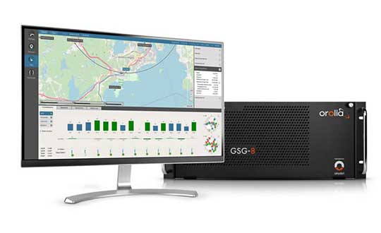
Photo: Orolia
The GSG-8 is an advanced software-defined simulator that offers ultra-high performance and flexibility in an easy-to-use format. It was developed to deliver the highest standard of GNSS signal testing and sensor simulation performance in an upgradable, scalable platform. The GSG-8 uses the robust 1000-Hz Skydel software engine. It is designed for customers who require complex capabilities to validate product and program performance in harsh, high-risk environments where failure is not an option, such as government agencies, space programs and specialized commercial programs.
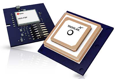
The Edge Locate GNSS L1/L2/E5 module combines antenna, RF electronics and receiver technology to deliver reliable centimeter-level positioning for the internet of things (IoT). It provides 1- to 3-centimeter-level accuracy using multi-band GNSS technology. With Edge Locate, manufacturers can quickly and effectively build devices with centimeter-level positioning technology. Its multi-band GNSS positioning can be used in conjunction with real-time kinematic (RTK) positioning capability. It uses a common connector for integration into any electronics device. It also connects directly to the Taoglas Edge board for immediate connectivity options.
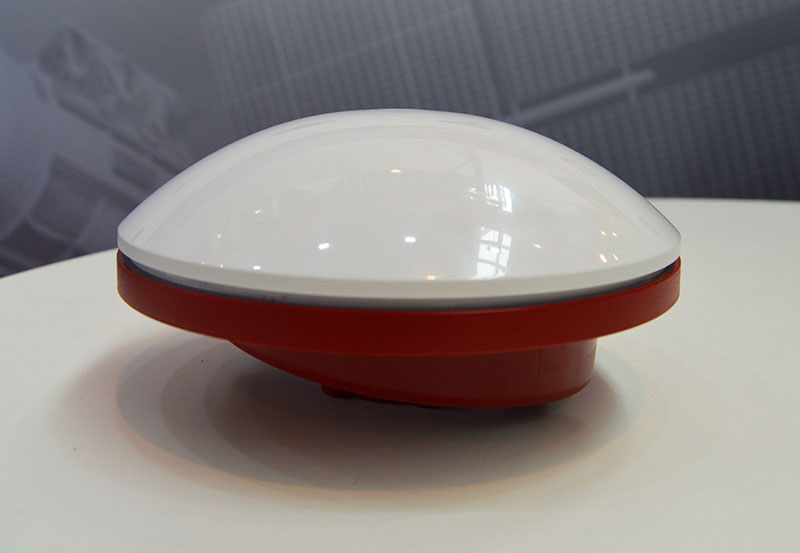
The VSP600L VeroStar precision antenna supports the full GNSS spectrum, as well as L-band correction services, and provides low-elevation satellite tracking with a high-efficiency radiating element. It is suitable for real-time kinematic (RTK) and precise point positioning (PPP) applications, and features a light, compact and robust design. It also has a low axial ratio through all elevation angles, providing strong multipath rejection. The VSP600L VeroStar provides high receive gain over the full GNSS spectrum: low GNSS band (1164 MHz to 1300 MHz), L-band correction services (1539 MHz to 1559 MHz) and high GNSS band (1559 MHz to 1610 MHz).
Tallysman, www.tallysman.com
L1 + L5 chip
Suitable for IoT and auto OBD
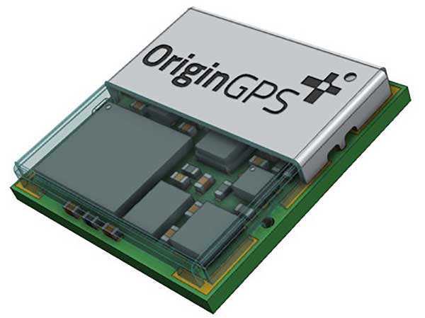
Photo: OriginGPS
The ORG4600-B01, OriginGPS’ first dual-frequency GNSS module, is supported by the BCM47758 chip, enabling ultra-accurate GNSS positioning. It was developed for solutions requiring super-precision GNSS and a dual-frequency combination. The module enables customers to build solutions with sub-1-meter accuracy without implementing external components. Measuring 10 x 10 millimeters, the ORG4600-B01 supports L1 + L5 GNSS reception with one RF port, enabling use of a low-cost, dual-band antenna delivering sub-1-meter accuracy performance in real-world conditions. An alternate build option allows for separate L1/L5 RF outputs when dual antennas are required. The module is suitable for solutions requiring ultra-accurate positioning, such as telematics, the internet of things (IoT) and auto OBD applications.
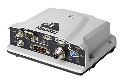
The PwrPak7-E2 contains an advanced Epson G370N MEMS inertial measurement unit (IMU) to deliver NovAtel SPAN technology in an integrated, single-box solution. It has a powerful OEM7 GNSS engine, built-in Wi-Fi, onboard NTRIP client and server support, and 16 GB of internal storage with higher performance and INS data rate. Connection options include serial, USB, CAN and Ethernet. Features include a 555-channel, all-constellation, multi-frequency positioning solution and multi-channel L-band that supports TerraStar correction services. It can be paired with an external receiver to support ALIGN GNSS azimuth aiding for low dynamic applications.
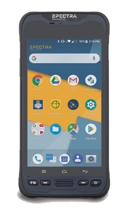
The MobileMapper 60 is a durable, efficient and accurate handheld device for geographic information system (GIS) and professional data-collection applications. The all-in-one GNSS receiver and smartphone offers 2-4 meter positioning accuracy in an all-weather design with a hand strap. It operates in extreme temperatures and rugged field conditions. It features a 6-inch high-resolution screen, large capacity all-day battery, Android 8.0 operating system and 2.2-GHz processor. Its 4 GB of memory and 64 GB of storage can manage large data sets with ease and speed. Bluetooth 4.1, 4G LTE and Wi-Fi capable, the MobileMapper 60 is suitable for cadastral, survey, topography and forestry.
Spectra Geospatial, spectrageospatial.com
Outdoor AR
Enables visualization of 3D data
Photo: Trimble
The SiteVision outdoor augmented reality (AR) system enables users to visualize 2D and 3D data with cellular or internet connectivity for planning, collaboration and reporting. Combining hardware and software in an integrated, lightweight handheld or pole-mounted solution, users can view 3D models and assets in a real-world environment at a 1:1 scale, from any angle or position. SiteVision integrates a Trimble Catalyst DA1 antenna, electronic distance measurement (EDM) rangefinder and power management into a lightweight, handheld device that connects to a user-supplied Android mobile phone. The SiteVision subscription is available monthly or yearly, and combines Trimble’s high-accuracy positioning services and cloud-based processing technology to create a centimeter-accurate AR system. Users can visualize digital models from a wide range of data collection, design and constructible modeling tools in open industry-standard formats, including IFC and LandXML. For civil projects, SiteVision accurately visualizes data from Trimble’s Quantm, Business Center and Novapoint; design data from Civil 3D and Bentley OpenRoads; and GIS data from Esri ArcGIS software.
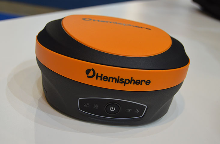
The S621, powered by the Phantom 40 GNSS OEM board, is a redesign of Hemisphere’s previous S321+. It processes and supports more than 800 channels with flexible and scalable simultaneous tracking of every modern and planned GNSS constellation and signal including GPS, GLONASS, BeiDou (including Phase 3), Galileo, QZSS, IRNSS, SBAS and Atlas L-band. The S621 combines Hemisphere’s Athena GNSS engine and Atlas L-band correction technologies with a new web user interface. It meets IP67 requirements and is immune to magnetic interference. It is designed for use in land or marine survey, GIS, mapping, construction or other applications requiring high-performance precision and positioning.
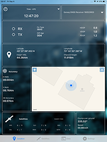
Records and transfers raw data for post processing
Photo: Geneq
The SXblue ToolBox is now available for iOS-compatible devices. The application was developed with special interest paid to raw data recording and NTRIP service connection. The Android application debuted in 2018. With the new iOS application, iPhone and iPad users can analyze the position data provided by the SXblue receiver, as well as location metadata. The application can record, save and transfer raw data from the GNSS receiver, thereby allowing post-processing activities. The application also acts as an NTRIP client, capable of connecting to an NTRIP server for real-time kinematic (RTK) corrections, and thus allows the receiver to issue very accurate location information. Receiver configuration is easy through the application, with the ability to set up and save user-defined commands for subsequent use. The settings include constellation to be used, differential source, NTRIP login credentials list and more.
TRANSPORTATION
Telematics for Ford
Simplifies mixed-fleet management
Photo: Ford
The Geotab Integrated Solution for Ford Vehicles integrates Ford vehicle data into the MyGeotab platform to give fleet managers a dedicated portal to process data. Ford Data Services securely transfers data from Ford vehicles with a factory installed or plug-in modem to Geotab’s cloud environment. It provides access to the Geotab Marketplace, a portfolio of mobile apps, hardware add-ons and software add-ins.
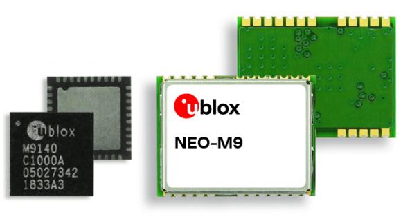
The M9 platform is designed for demanding automotive, telematics and UAV applications. With the u-blox UBX-M9140 GNSS chip, the M9 technology platform and the NEO-M9N (the first module based on the platform) can receive signals from GPS, GLONASS, BeiDou and Galileo concurrently. It can achieve high positional accuracy in difficult conditions such as deep urban canyons. The M9 offers a position update rate of up to 25 Hz, enabling dynamic applications to receive position information with low latency and has special filtering against RF interference, jamming and spoofing. U-blox also provides Explorer Kit M9 (XPLR-M9) for developers.
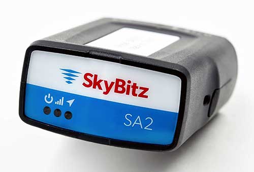
The SA2012 GPS tracker is equipped with the latest 4G LTE with 3G fallback. It is designed for customers looking for a scalable vehicle telematics solution. The hardware can be installed using the SkyBitz Ops Center mobile device, either directly plugging it into the vehicle diagnostic port or covertly installing it behind the dashboard. Once installed, the device feeds into the Ops Center platform, where users can manage the new device and others via a single interface. Coverage is across North America.
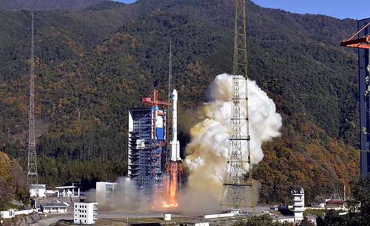
China successfully sent two satellites of the BeiDou Navigation Satellite System (BDS) into space from Xichang Satellite Launch Center in Sichuan Province at 15:22 on Dec. 16.
So far, 24 medium earth orbit (MEO) BDS-3 satellites have been successfully sent into space, and the deployment of the core BDS-3 constellation system has been completed, according to Yang Changfeng, chief designer of the BDS.
Launched on a Long March-3A carrier rocket, the two satellites entered preset orbit after a more than three hours of flight, according to XinhuaNet, China’s official news service.
The launch was the 321st mission for the Long March series carrier rockets and the 108th mission for the Long March-3A carrier rocket.
In June, China stated its plan to complete the BDS-3 constellation by 2020.
Yury Urlichich, First Deputy Director General, Roscosmos. (Photo: Roscosmos)
By Yury Urlichich, First Deputy Director General of ROSCOMOS State Space Corporation Sergey Karutin, Designer General of GLONASS Nikolay Testoedov, Director General, Information Satellite Systems
Roscosmos keeps concentrating on user needs as it did in previous years. Growing digitalization is driving a high demand for high-accuracy navigation services. Space information technologies support user needs by modern digital services, including increasing accuracy of position and velocity determination. Because of this, it is of vital importance for us to ensure that GLONASS provides continuous services and stable performance.
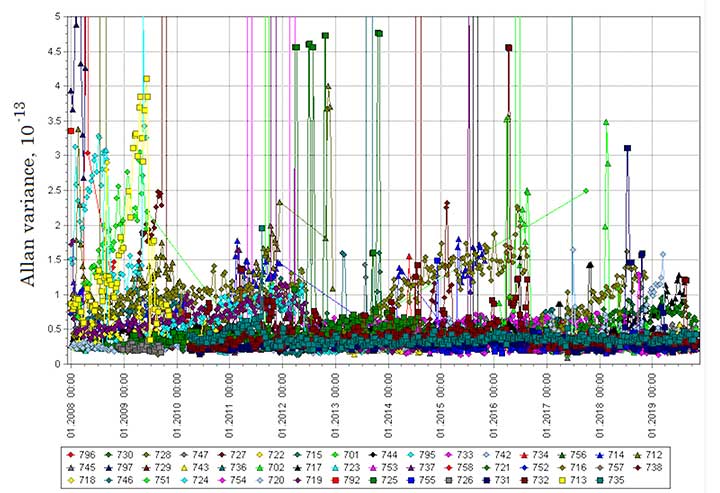
Figure 1. Mature Glonass-M satellites show improved cesium frequency standards performance in terms of daily stability. (Image: Roscosmos)
Performance Standard & ICD
This year, we finished drafting the GLONASS Open Service Performance Standard (GLONASS OS PS; the Russian language version is available). In 2020, the new version of the GLONASS Interface Control Document (ICD) also will be publicly available.
GLONASS OS PS serves as a high-level mainframe document specifying the values of the achieved GLONASS performance characteristics plus the significant guaranteed margin. These, coupled with the signal reception environment and a priori estimation of user equipment performance characteristics, can further be translated into the performance that an end user can expect to achieve in his specific PVT solution.
This GLONASS OS PS is a basis for certification of GLONASS services and development of lower level standards for user receiver and GLONASS-based service, as well as for development of international standards like those of the International Civil Aviation Organization (ICAO), the International Maritime Organization (IMO) and others.
Use of the unified set of performance parameters and calculation methods for all GNSS — GLONASS, GPS, Galileo and BDS — is a conventional practice. The similar standards for GPS, Galileo and BDS have been published and are regularly updated.
In fact, this GLONASS OS PS is the second one after the ICD baseline interface between GLONASS and user receiver manufacturers and the GLONASS-based services developers. The OS PS establishes the minimum performance that can be achieved by users with a high level of trust based on the system’s long-term statistical history.
Signal-in-Space. This OS PS specifies standards for the GLONASS OS Signal-in-Space (SIS) performance neglecting receiver biases, signal propagation and reception biases (in terms of performance metrics used to specify system performance, that is, taking into account the GLONASS space segment and the GLONASS ground segment contributions to the performance). It can serve as a basis for certification of the GLONASS-based services and receivers incorporating GLONASS, including those used in aviation and other user domains.
The OS PS provides an overview of the GLONASS system and an overview of the GLONASS Open Service SIS. It specifies the standards for the performance characteristics of the channel of standard accuracy used to provide the Open Service, and lists the legal reference documents.
L3 CDMA. One of the most significant tasks is the harmonization of GLONASS user interfaces with respect to new L3 CDMA signals. The requirements related to the interface between the space segment of GLONASS and the navigation user segment for radio frequency links is established by the GLONASS ICDs.
The new version of ICD for CDMA L1, L2 and L3 signals to be broadcast by new-generation Glonass-K2 satellites was issued in 2016. However, the Glonass-M satellites (## 755-758) and the Glonass-K satellites currently in orbit transmit the L3 signal as per the L3 Open Access CDMA Radionavigation Signal Interface Control Document (Edition 1) of 2011.
In order to mitigate the above-mentioned discrepancies, five reference documents (Interface Control Documents for open-access signals) have been updated and prepared for publication. In addition, flight tests to verify new ionospheric and tropospheric delay models have been scheduled.
Incorporating More Data
The new ICDs for open access and authorized signals incorporate changes related to the introduction of additional data into the spare bits of the navigation message. This additional data is to be used by user receivers for better PVT solution purposes.
The updated versions of ICDs will incorporate:
The mathematical ionospheric delay model and inclusion of the model parameter into the navigation message.
The mathematical tropospheric delay model, which does not require that any specific parameters be included into the navigation message. It only employs data on the latitude of a user receiver location and the season (i.e., winter, spring, summer, and autumn).
The attribute (or flag) to inform a user that a satellite is in the turn mode and its antenna phase center behavior is different from that when a satellite is in the sun orientation mode.
Information about the types of signals broadcast on the L1, L2, and L3 frequencies; 5-bit field, in which the first three bits denote L1, L2, and L3 CDMA signals, respectively, while the 4th and the 5th bits denote L1 and L2 FDMA signals, respectively.
A 5-bit field to be used to broadcast age of data (AOD) for time offsets in addition to the similar field used to broadcast AOD for ephemerides.
Backward Compatibility. The updated CDMA and FDMA ICDs will support the backward compatibility for the uninterrupted operation of the existing envelope of user equipment and the introduction of the ionospheric and tropospheric model parameters into the message spare capacity.
Constellation Refresh
The GLONASS constellation has been replenished steadily. Since 2013, we have been launching one to two satellites a year, and this year is not an exception. The launch on May 27 and the December launch will help sustain the nominal constellation. The Glonass-M satellites demonstrate good dynamics for the average operational life. Two satellites are well beyond their 10-year design life — their operational lifetime has exceeded 12 years. As some of the Glonass-M satellites grow older, their cesium frequency standards performance in terms of daily stability improves (see Figure 1).
Glonass-K. In 2020, the launch campaign for the Glonass-M satellites will come to its end. The Glonass-K satellites will come on stage with the first launch of Glonass-K-15 scheduled for the beginning of the next year. We are fully confident that this satellite will not disappoint our users.
By Javier Benedicto
Head, Galileo Programme department,
European Space Agency
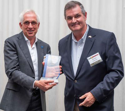
Javier Benedicto, left, accept the 2018 GPS World Satellites Leadership Award on behalf of Giuliano Gatti of the European Space Agency, from Phil Froom of Rockwell Collins. (Photo: Melanie Beus)
Since the Galileo initial services declaration in December 2016, the Galileo Program has been providing global PNT and search-and-rescue services for users worldwide. The European GNSS Agency (GSA) just issued its GNSS 2019 Market Report in October, providing a complete overview of the current status and trends of the GNSS worldwide market with focus on European GNSS (Galileo and EGNOS) applications and services.
In parallel with service provision, the Galileo Program is undertaking extensive infrastructure development and deployment activities to reach Full Operational Capability (FOC), incorporating new service capabilities, but above all aiming at increasing the robustness and resilience of the system infrastructure, operations and service provision.
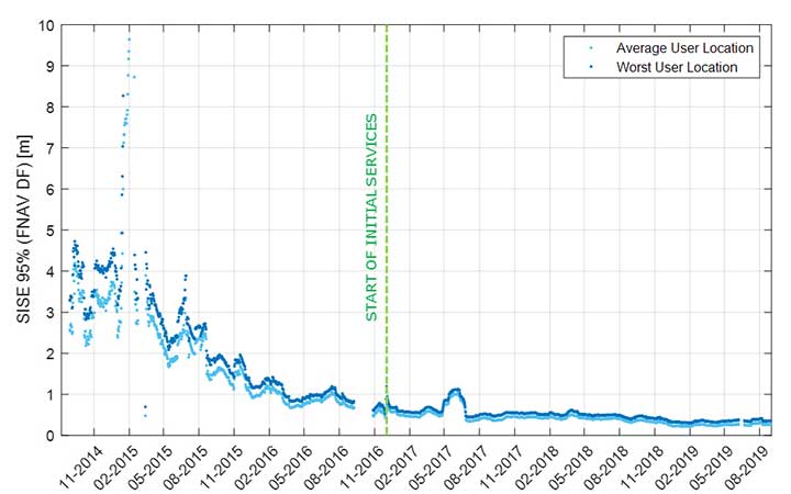
Galileo’s signal-in-space quality has steadily improved over the past few years, reaching in 2019 a best signal-in-space error (SISE) of about 0.25 meters (95%, global average; Figure 1). This has been achieved through a combination of several factors, including the increased number of operational satellites, enhanced versions of the Ground Mission Segment, and higher uplink rate of the navigation message (lower age of data). This performance is well within Galileo’s initial service accuracy commitments, as defined in the public Open Service – Service Definition Document (OS SDD).
Figure 1. Long-term historical SISE plot over a 30-day sliding window, constellation averaged. (Image: ESA)
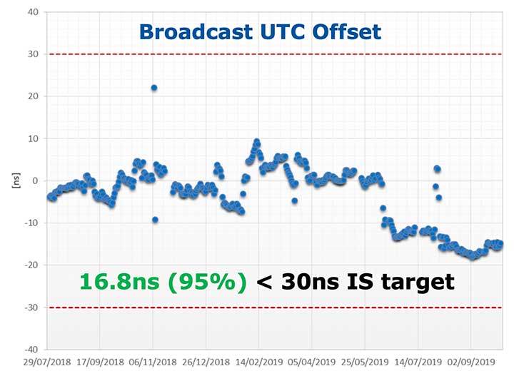
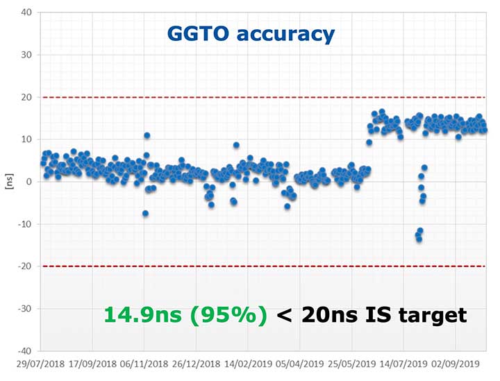
Figures 2 and 3 (see page 40) show Galileo’s timing performance as broadcast UTC offset and GGTO accuracy. The evaluation was performed with calibrated GPS/Galileo timing receivers operated in UTC(k) laboratory (PTB, INRIM). Again, the initial timing service commitments have been fully met.
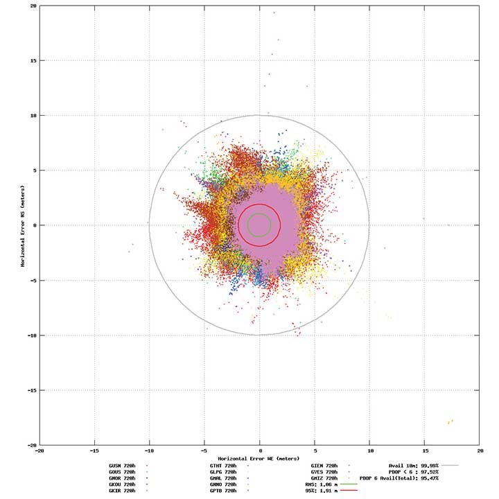
Probably the most significant discriminator of Galileo compared to other GNSS is its capability to broadcast multi-frequency (E1, E6, E5) signal components on all operational satellites. The position performance of a dual-frequency user receiver on-ground is shown in Figure 4. This measurement from June 2019 demonstrates a Galileo position accuracy well below 2 m (95%).
Figure 4. Galileo position accuracy performance, dual-frequency, June 2019. (Image: ESA)
With the aim of further improving the Open Service (OS) performance, three newly introduced I/NAV message improvements on Galileo E1-B are under implementation, namely FEC2 Reed-Solomon Clock and Ephemeris (CED), Reduced CED, and Secondary Synchronization Pattern (SSP). Galileo Open Service (OS) users will benefit from improved robustness in terms of navigation data retrieval in challenging environments, in addition to facilitating a reduced time to first fix. Those I/NAV improvements on Galileo E1-B are backwards compatible with previously released OS SIS ICDs.
In addition, Galileo infrastructure is currently being upgraded to provide means for OS authentication. The protocol proposed uses the E1B External Data Broadcast Service (EDBS) to provide authentication data to the user. The OS Navigation Message Authentication (NMA) is based on an adaptation of the Timed Efficient Stream Loss-tolerant Authentication (TESLA) protocol.
Beyond the OS, the Galileo system has been designed to allow for the dissemination of value-added data, such as high accuracy and authentication, in the E6B signal component. The component has been designed to broadcast the Galileo High Accuracy Service based on the provision of accurate satellite data (clocks, orbits and biases) and atmospheric data (mainly ionospheric corrections) to enable multi-frequency multi-constellation PPP with correction data transmitted through an open format in the Galileo E6B signal.
The introduction in early 2020 of the automatic acknowledgment of the SAR/Galileo Return Link Message (RLM) as part of the Cospas-Sarsat system will enable space assets to be used for search and rescue — persons in distress will get swift acknowledgement that their alert has been detected and located. The Return Link is the means to interact with a SAR beacon, improving the effectiveness of SAR operations. Extensive testing has demonstrated that the median latency for the reception of a return link message on the ground is 14.2 seconds, while 99% of messages are received within 57 seconds, after the request for the RLM transmission is delivered to Galileo (from Cospas-Sarsat to the RLSP). At the same time, the measured rate of reception was 100%, considering line-of-sight availability, thanks to the very robust Galileo navigation data link. This performance has been demonstrated to be uniform across the globe, as shown in Figure 5.
Figure 5. Beacon activation map and RLM delivery latency through the Galileo system. (Image: ESA)
Following the re-profiling of the Galileo Safety-of-Life (SoL) service, Galileo is meant to be exploited through dual-frequency multi-constellation (DFMC) SBAS and will support the provision of integrity through the concept of Horizontal Advanced Receiver Autonomous Integrity Monitoring (H-ARAIM). To allow the exploitation of Galileo for these SoL applications, a thorough analysis of the actual signal-in-space (SiS) performance and of potential feared events critical for SoL users is key. In this context, the Galileo Integrity Failure Mode and Effect Analysis (IFMEA) process is implemented through measurements and review of the system design, including feared-events characterization.
Ground Segment Brings Robustness
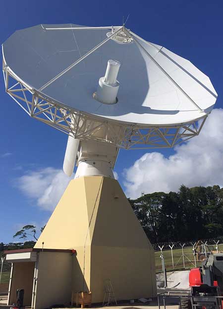
Galileo telemetry and telecommand ground station. (Photo: ESA)
Galileo’s Ground Segment is being upgraded to fully redundant control centers. These include processing and storage, monitoring and control facilities, and security monitoring centers. A worldwide network of Galileo Sensor Stations (GSS) allows monitoring and measuring of satellite signals; uplink stations allow dissemination of the navigation message to users through Galileo satellites; and telemetry, tracking and control (TTC) stations allow monitoring and control of the satellites.
Ground segment upgrades under production by Thales Alenia Space France (in charge of the ground mission segment and security monitoring) and GMV Spain (in charge of the ground control segment) are addressing increased service robustness, through the introduction of a more flexible infrastructure with a significant technology refresh, improved security, service continuity, enhanced service performances, and enhanced operability features.
One important objective of the ongoing upgrades is to implement a modern infrastructure, based on leading virtualization technologies. This modernized infrastructure will make it possible to easily accommodate hardware and software changes without requiring significant redesign or requalification, and will minimize the impact to Galileo service operations — under responsibility of Spaceopal GmbH — during future deployment activities.
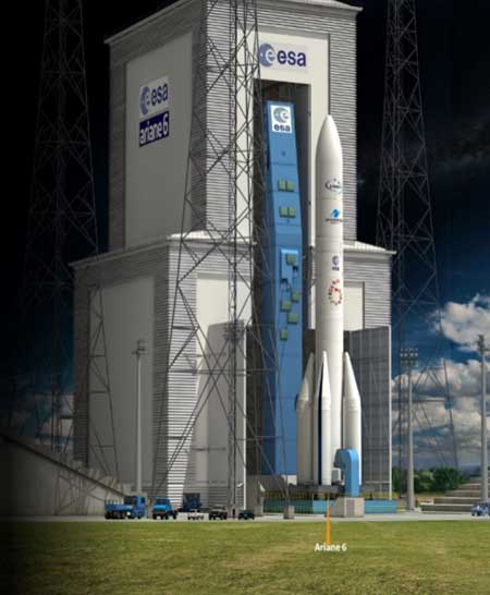
Batch 3, Ariane 6 Under Production
Ariane 6 on the launchpad. (Artist’s concept: ESA)
The production of Batch 3 of 12 additional Galileo FOC satellites is proceeding, aiming at readiness for launch by the end of 2020 onward. The satellite design includes a selected number of improvements compared to the 22 FOC satellites launched previously and built by the same satellite manufacturer OHB Systems.
The different stages of assembly, integration and initial test phase in the OHB production plant in Bremen have already started, before shipment to ESA-ESTEC in the Netherlands for the environmental test campaign consisting of thermal vacuum, mechanical tests, interface verification with the launcher and system end-to-end performance tests with the elements of the Galileo ground segment.
Following the phasing out of the Ariane 5 SE launcher, the third batch of Galileo satellites will be progressively launched with the new Ariane 62 launcher vehicle, the two solid-booster variant of Ariane 6 now in the final stages of development.
Evolution to Meet User Needs
The Galileo Second Generation roadmap has achieved maturity in 2019 and is now entering the preliminary design and implementation phase. Based on the EU’s H2020 Galileo Second Generation activities managed by ESA, and the GSA prospective market analysis, the European Commission, in close consultation with EU member states, has agreed on an ambitious set of long-term PNT goals for the future European GNSS infrastructures.
Technology pre-developments, critical engineering activities and synergic design activities between space and ground infrastructure are being conducted. This will translate into the progressive deployment of a complete set of space/ground infrastructure that is tailored to satisfy the diversified user needs in four main dimensions:
Satellite and ground segment infrastructure with capabilities that can dynamically adapt to current and future user needs. Key drivers are flexibility and robustness, ensuring fast time to market to meet user needs.
Full synergy between GNSS and SBAS systems infrastructure, to complement and enhance the service portfolio. This will allow segmentation and complementarity of safety-critical services and extension to all new PNT services available today, including high-accuracy positioning integrity.
Enhanced integration with terrestrial systems — 5G/6G, signals of opportunity (SOOP), terrestrial beacon systems (TBS). ESA and GSA have been actively leading the 5G positioning standardization worldwide in collaboration with public and private institutions inside 3GPP and will soon move toward the start of standardization of 6G terrestrial positioning and GNSS interconnection technologies.
Full complementarity with external sensors (such as INS, barometer and lidar) and application environments (low-power devices and internet of things) so that the Galileo Second Generation Infrastructure enhances and complements the capabilities provided by these external means.
A key pillar for this long-term strategy is the Galileo transition satellites. The competitive procurement procedure for the first batch of transition satellites is coming in 2020. The flexibility and robustness of these satellites will allow the European PNT infrastructure to satisfy all the different user needs in the next decade. This procurement — together with others at system, ground segment and technology level — will enable the start of the in-orbit validation of second-generation capabilities from 2025 onward.
Additional ground and test infrastructure are in early engineering analysis, design and technology development, in order to proceed with additional procurements for experimental and operational usage, starting early in the 2020s.