Tells Space Advisory group spectrum issues a concern for all
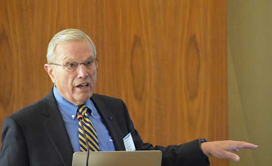
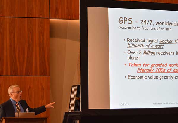
Speaking to a gathering of space industry leaders, Dr. Brad Parkinson, the original chief architect for establishment of the Global Positioning System, outlined the threats to GPS signals posed by a proposal from Ligado Networks that is before the Federal Communications Commission (FCC).
The proposal, which was initially approved, has been pending since 2011 over concerns about its impact on reception of GPS signals.
When asked why the proposal has been pending for so long, Parkinson speculated a combination of the enormous sums of money potentially involved and difficulties for the FCC in arriving at an equitable solution were to blame.
“I hope they find some spectrum for Ligado,” he said. “Just not the spectrum they are asking for.” Referring to the powerful proposed transmissions in frequencies adjacent to those used by weak GPS signals, he said “You don’t want to put a rock band next to a retirement home.”
“You don’t want to put a rock band next to a retirement home.”
Parkinson was speaking to the National Space Council’s User Advisory Group (UAG). The UAG was chartered under the Federal Advisory Committee Act in December 2017. Membership includes the CEOs of Lockheed, Boeing and other companies with interests in space, the Governor of Alabama, five former astronauts, and other leaders in space technology and policy.
This was the first time the UAG’s agenda focused on GPS and positioning, navigation, and timing issues. Parkinson was invited to discuss the activities of the U.S. National Space-based Positioning, Navigation, and Timing Advisory Board. The UAG was interested in learning from the PNT Advisory Board’s experience, and about some of the issues it has encountered over the 15 years since its establishment in 2004.
Parkinson used the PNT board’s experience with adjacent band compatibility and the Ligado proposal as an example of a particularly thorny issue. He said the Ligado issue was an ongoing concern that the UAG should share.
Brad Parkinson shared his concerns over lack of Ligado decision with the National Space Council’s User Advisory Group (UAG). (Photo: Rebecca Zia)
Also that spectrum issues writ large should be of great concern to all users of space as the competition for spectrum from terrestrial users will continue increase. He called the Ligado proposal “a grave threat to GPS,” especially for aviation and high-precision users.
During the course of the presentation Parkinson asked for the UAG’s support of the PNT Board’s recommendations on the Ligado proposal. He also asked the group to endorse the National PNT Executive Committee’s adjacent band compatibility methodology to any future such proposals.
Parkinson’s presentation concluded with a discussion of how GPS is increasingly being used to support activities in space. It has long been used for booster guidance during the initial phase of space flight.
Relatively recent work using side lobe signals from GPS satellites has caused engineers to recognize a Space Service Volume for GPS. This allows use of the signals for mid-course launch corrections, satellite station-keeping, rendezvous, and potentially trans-lunar navigation.
Bentley is a global provider of comprehensive software and digital twin cloud services for advancing the design, construction, and operations of infrastructure, and Topcon is a leader in positioning technology for the survey and construction industries.
The companies made the announcement at The Year in Infrastructure Conference, held Oct. 21 in Singapore.
Digital Construction Works has a global staff of digital construction experts and provides digital automation, integration and “twinning” services around a portfolio of fit-for-purpose software and cloud services from Topcon, Bentley, and other software vendors. The venture was created to realize the “breakthrough potential of constructioneering” for industrializing construction, according to a press release.
Bentley Systems and Topcon joined forces in 2016 to jointly develop enhanced integration between their respective MAGNET and ProjectWise cloud services so that engineering and construction workflows could be integrated for improved project quality and performance.
Since then, Bentley and Topcon have continuously introduced innovations in surveying, reality modeling, scheduling and logistics, work packaging, machine control, and progressive assurance for construction.
In 2017, they opened Constructioneering Academies, including at Topcon’s “sandbox” facilities, for construction professionals to experience new digital best practices, first-hand. During 2018, the companies assimilated Bentley’s SYNCHRO and Topcon’s ClearEdge3D acquisitions into constructioneering offerings.
Digital Construction Works is chartered to embed its experts within constructors’ major project teams to advance and optimize constructioneering processes for delivering better design-build outcomes.
Through its digital integration services, to connect and automate constructors’ existing processes with constructioneering, Digital Construction Works can make the best projects better while also helping to institutionalize these digital workflows throughout a constructor’s full project portfolio, the companies said.
At the same time, experiences gained by Digital Construction Works will help guide Bentley Systems and Topcon in prioritizing their constructioneering software development investments.
Digital Construction Works is led by CEO Ted Lamboo, previously senior vice president of strategic partnerships for Bentley Systems, and COO Jason Hallett, formerly vice president of digital construction and business development for Topcon.
Greg Bentley, CEO of Bentley Systems, said, “When we and Topcon recognized the opportunity for constructioneering to finally industrialize capital project delivery, we committed respectively to completing its software requirements. Indeed, our new software capabilities make possible construction digital twins—converging digital context, digital components, and digital chronology. What remains, in going digital for infrastructure construction, is for constructors’ people and processes to take advantage of the technology. We and Topcon have now in turn committed many of our best resources, professionals experienced in both construction and software, to serve shoulder-to-shoulder, in virtual hardhats, to innovatively advance the required digital integration. The Digital Construction Works joint venture has the full management and capital commitments of both our companies, multiplying its unique strengths for helping to realize constructioneering’s potential to close the world’s infrastructure gap.”
Ray O’Connor, president and CEO of Topcon Positioning Systems, said, “What Topcon and Bentley Systems initiated in recent years was done in the spirit of changing mindsets and processes on how we approach construction, and that collaboration has led to the development of this joint venture. The creation of Digital Construction Works perfectly aligns with our focus of helping the industry succeed in meeting infrastructure demands through technological innovations. Through the new organization, companies will have the opportunity to integrate hardware and software capabilities to more quickly and efficiently adopt new technology for more rapid productivity improvements. With customized services to address the individual needs of an organization, widespread adoption and technology improvements can be more readily realized. We are excited to take this journey with Bentley Systems in moving the industry forward.”
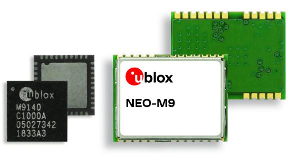
The ultra-robust M9 technology platform will suit demanding automotive and high-end telematics.
U-blox, a global provider of positioning and wireless communication technologies, has launched its new ultra-robust meter-level M9 global positioning technology platform, designed for demanding automotive, telematics and UAV applications.
Because of the high-performance GNSS UBX-M9140 chip, the M9 technology platform and the NEO-M9N (the first module based on the platform) can receive signals from up to four GNSS constellations (GPS, GLONASS, Beidou and Galileo) concurrently. It can achieve high positional accuracy even in difficult conditions such as deep urban canyons, u-blox said in a press release.
The u-blox M9 offers a position update rate of up to 25 Hz, enabling dynamic applications like UAVs to receive position information with low latency. It also features special filtering against RF interference and jamming, spoofing detection and advanced detection algorithms that enable it to report fraudulent attacks quickly so that users’ systems can react to them in a timely fashion.
A SAW (surface acoustic wave) filter combined with an LNA (low noise amplifier) in the RF path is integrated in the NEO-M9N module. This setup guarantees normal operations even under strong RF interferences, such as when a cellular modem is co-located with the NEO-M9N.
“We’ve developed the u-blox M9 as a follow-on from our very successful u-blox M8 GNSS platform, offering even more robust meter-level positioning technology and security features to protect the integrity of applications in the automotive, telematics, and UAV markets,” said Bernd Heidtmann, product manager, Product Strategy GNSS, Product Center Positioning, at u-blox.
Users of the u-blox M9 will benefit from it being part of the wider u-blox product family, which means that developers will be able to design a single PCB and then migrate to a different positioning technology — such as dead-reckoning augmenting GNSS technology — with little change to the board design.
Explorer kit released
U-blox has also released the Explorer Kit M9 (XPLR-M9), a development board for designers who want to assess the technology. The miniature plug-and-play device is supplied with user-friendly u-start software, which includes preset scenarios to enable users to explore the performance of the new device.
The u-blox M9 technology platform complies with the ISO/TS 16949, ISO 16750, AEC-Q100 standards. Engineering samples of the NEO-M9N, the first module based on the M9 platform, the UBX-M9140 high-performance chip, and the Explorer Kit are available now.
To learn more about M9, visit the u-blox booth, Hall South, S.2702, at Mobile World Congress 2019 in Los Angeles, Oct. 22-24.
Satelles Inc., provider of highly secure satellite-based time and location services, has raised $26 million in Series C funding. C5 Capital led the round, with participation from Iridium Communications and existing investors.
The new investment brings Satelles’s total funding since the launch of its platform to $39 million and will help the company expand its sales and marketing efforts, broaden its partner network, and accelerate product development.
In 2016, Satelles demonstrated sub-microsecond timing using its Satellite Time & Location (STL) service with a stand-alone TCXO-based receiver. In February 2018, the company released new tests using configurations with a differential source and with a more accurate OCXO clock, producing timing accuracy of 160 nanoseconds.
Industry and government requirements for positioning, navigation, and timing (PNT) are expanding at a rapid pace, and the Satellite Time and Location (STL) broadcast signal from Satelles provides assured PNT across a range of applications and at scale.
“Today’s world runs on systems requiring trusted time and location information, and C5 Capital shares our commitment to make it a more secure and better place,” said Michael O’Connor, CEO of Satelles. “We are delighted that C5 led this latest investment round because they bring great insight into cybersecurity, and their international network is unparalleled.”
Attacks such as jamming and spoofing — where a radio transmitter near the target is used to interfere with legitimate GPS or GNSS signals — and hacking are becoming more of a threat because of the key role that GPS and GNSS play in the operation of critical infrastructure.
The STL signal strength is much greater than GNSS because the LEO satellites are much closer. (Slide: Satelles)
According to the company, the Satelles STL platform brings security to telecommunications networks, financial exchanges, electrical grids, maritime transportation systems, and many other sectors that depend on timing or location information.
Downtime or malfunctions in these systems due to such attacks would be very costly. A June 2019 report sponsored by the National Institute of Standards and Technology estimated a $45 billion loss to the U.S. economy if GPS were to experience a 30-day service disruption.
The Satellite Time and Location broadcast service from Satelles is encrypted to thwart malefactors aspiring to spoof or otherwise disrupt the STL signal, which is delivered via the low-Earth-orbit (LEO) satellite constellation operated by Iridium, an investor in this financing round.
“STL addresses a critical and growing need across many applications and industries, so Iridium’s investment in Satelles aligns with our strategic vision,” said Matt Desch, CEO of Iridium Communications. “Satelles’s technology is unique and powerful, and we are proud to host such an innovative service that solves important problems and leverages the unique capabilities of our network.”
The Iridium satellite constellation-based system offers many advantages:
A signal 1,000 times stronger than GPS/GNSS is better at reaching users and facilities in GPS/GNSS-challenged environments such as inside buildings, underground locations, and urban canyons.
Overlapping and constantly moving spot beams enable revolutionary cybersecurity solutions that can rely on trusted time and location for authentication and data access.
Polar-orbiting, cross-linked satellites ensure truly global coverage.
The L-band frequency range allows small, low-cost equipment to receive the Satelles STL signal.
“The capabilities of Satellite Time and Location are enhanced by the technical and service delivery attributes of low-Earth-orbit satellites,” said Dr. Gregory Gutt, President and CTO of Satelles. “An extraordinary constellation such as Iridium’s gives us an incredible platform from which to deliver our trusted PNT solutions, so we remain committed to LEO technologies going forward.”
Commenting on the closure of the Series C investment in Satelles, Andre Pienaar, Managing Partner of C5 Capital, said, “Space is a rapidly developing battleground for cyber threats to critical infrastructure, and GPS is unable to meet all these challenges. Satelles has developed a powerful solution which not only prevents attacks but provides a stronger and more effective service through STL. We are pleased to have led this funding round and look forward to working closely with this remarkable business.”
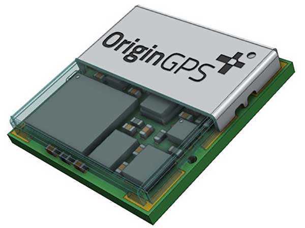
OriginGPS has collaborated with Broadcom to create a new miniature module with L1 + L5 support provided by the BCM47758 chip, enabling ultra-accurate GNSS positioning. The module was developed for solutions requiring super-precision GNSS and a dual-frequency combination.
Photo: OriginGPS
The ORG4600-B01 is OriginGPS’ first dual-frequency GNSS module. The module enables customers to build solutions with sub-1-meter accuracy without implementing external components.
Measuring 10 x 10 mm, the ORG4600-B01 module supports L1 + L5 GNSS reception with one RF port, enabling the use of a low-cost, dual-band antenna delivering sub-1-meter accuracy performance in real-world operating conditions.
Alternate Build. An alternate build option allows for separate L1/L5 RF outputs when dual antennas are required. The ORG4600-B01 is suitable for solutions requiring ultra-accurate positioning, such as telematics, the Internet of Things (IoT) and auto OBD applications.
“This year has seen several satellites launched into orbit every month, most of them fitted with L5/E5 capabilities, and the Chinese and European Union governments plan to have their satellite constellations fully operational by 2020.” said Haim Goldberger, CEO of OriginGPS.
Developing the ORG4600-B01 module with the BCM47758 GNSS receiver chip by Broadcom Inc. was the fastest and surest way to add a high-quality dual-frequency module to our portfolio and meet our customers’ increasing requirements for ultra-accurate GNSS modules,” Goldberger said.
“Size is a crucial parameter in GNSS dual-frequency solutions,” said Prasan Pai, product marketing director for the Wireless Communications and Connectivity Division at Broadcom. “The collaboration with OriginGPS has created the industry’s smallest dual-frequency module with ‘no compromise’ quality. For our customers seeking an ultra-accurate GNSS solution in a compact form factor, the ORG4600-B01 fits the bill. The collaboration enables Broadcom to reach new markets, such as precision agriculture, security, children tracking and fleet management.”
“OriginGPS is interested in additional partnerships to enable bringing advanced solutions to market quickly,” said Haim Goldberger, CEO of OriginGPS.
OriginGPS is presenting its products with real-life demonstrations at MWC 2019, Los Angeles, Oct 22-24, Booth S2938.
Geotab, an IoT and connected transportation company, now offers the Geotab Integrated Solution for Ford Vehicles. Integrating Ford vehicle data into the MyGeotab platform gives fleet managers one dedicated portal with powerful tools to process data from vehicles with an embedded modem as well as those which require a third-party device.
Through this integration, Ford Data Services will securely transfer data from Ford vehicles with a factory installed modem (or Ford Plug-In Modem, where required) to Geotab’s cloud environment, eliminating the need for third-party hardware in Ford vehicles.
A business unit of Ford Smart Mobility, Ford Commercial Solutions help fleets improve their operational effectiveness by offering OEM-grade data verified by Ford engineers such as fuel use and vehicle health alerts. The Transportation Mobility Cloud (TMC), an open platform that securely manages information flow to and from Ford vehicles’ embedded modems, facilitates both new products.
Simplifying the task of mixed-fleet management, the latest solution from Ford and Geotab provides fleet managers with the ability to oversee their entire fleet in one portal while also presenting the added benefit of access to the Geotab Marketplace, a portfolio of mobile apps, hardware add-ons and software add-ins that enable Geotab customers to further customize their fleet management solution.
“Ford Data Services provides the ‘Power of Choice’ so that businesses can get manufacturer-grade vehicle information from the telematics provider of their choice, such as Geotab,” said Michelle Moody, director at Ford Commercial Solutions. “With the launch of Geotab Integrated Solution for Ford Vehicles, fleets are able to access vehicle information such as fuel usage, vehicle health and driver behavior, through the Geotab platform for vehicles with a Ford modem.”
With the solution, fleet managers can access proprietary Ford-specific data available for all Ford 2020 or newer models in the United States.
“The Geotab Integrated Solution for Ford Vehicles will allow fleet managers to benefit from the combination of Geotab’s actionable data insights and powerful rules engine with the rich diagnostic data from Ford’s factory-fitted modem,” said Geotab’s Sherry Calkins, Vice President, Strategic Partners. “This means that regardless of whether they are utilizing an embedded or externally installed telematics solution, the entire fleet can be managed from one platform.”
Traditional tide gauges are in contact with the water surface and as a result are susceptible to measurement error and damage during extreme weather. An alternative approach is the use of GNSS reflectometry. We learn how this innovative use of satellite navigation signals works in this month’s Innovation column.
Innovation Insights with Richard Langley
Seawater level is conventionally monitored by tide gauges that measure the vertical distance of the water surface from a point on the ground. As the tide gauges provide seamless and highly accurate measurements, many countries operate a tide-gauge network to monitor sea-level changes and to assess flood risk. For example, the National Oceanic and Atmospheric Administration (NOAA) operates a permanent observing system, the National Water Level Observation Network (NWLON), with more than 400 gauges throughout the United States.
However, some challenges of tide gauges can be identified. Firstly, tide-gauge measurements require direct contact with the water, which causes limitations in installing and maintaining the equipment. The equipment requiring direct sensing is highly vulnerable to coastal hazards, such as coastal flooding and tsunamis, resulting in potential measurement errors or even equipment destruction during severe natural events.
Furthermore, tide gauges require maintenance on a regular basis, which is expensive because it requires the use of divers. This greatly limits the operation of tide gauges, especially in extreme environments such as in the Arctic. Alaska, for example, has significant gaps in its available spatially-varying tidal information. However, in the Arctic, it is also very important to constantly and closely monitor the long- and short-term variation of water levels because this area has a significant impact on global climate and ecosystems. Consequently, more support is needed for sea-level monitoring and coastal mapping in this region.
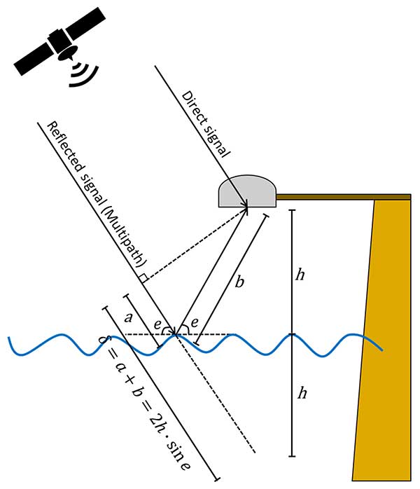
GNSS can serve as an alternative approach for water-level monitoring. GNSS satellites continuously transmit radio signals and ground-based, space-based, and airborne receivers access the signals regardless of weather conditions. Some of the received signals are reflected from obstacles or surfaces near the antenna, a phenomenon referred to as multipath (see FIGURE 1).
FIGURE 1. Schematic drawing of the GNSS-based tide gauge. (Image: Authors)
Multipath tends to be regarded as one of the major error sources for GNSS positioning where it causes unexpected phase delays when compared to the direct signal. Consequently, various procedures have been developed to mitigate the multipath effect. However, the GNSS signals reflected from the Earth’s surface contain information about the geophysical properties of the reflecting surface. The use of these signals is known as GNSS reflectometry (GNSS-R). GNSS-R allows us to monitor the temporal variation of water levels by calculating phase delays of GNSS signals reflected from the water surface. A GNSS-R-based tide gauge does not require direct contact with the water because it measures the water levels based on a remote-sensing technique. Thus, a GNSS-R-based tide gauge can be effectively applied to water-level monitoring.
However, several challenges exist in processing GNSS signals observed at high latitudes compared to mid-latitudes. Not only do we have to contend with extreme weather conditions and limited infrastructure availability, but also with problematic satellite geometry and ionospheric effects on the GNSS signals. To overcome these limitations in the use of GNSS-R in the Arctic, we introduce enhanced algorithms to improve the temporal and spatial resolutions of GNSS-R sea-level measurements.
Our approach includes an enhanced spectrum analysis based on multi-frequency signals and statistical reliability verification. Moreover, we include the signals transmitted by the Galileo constellation in addition to GPS to improve the quantity and the quality of GNSS observations in the Arctic. We have tested the proposed method with an experiment in Alaska and validated the results with nearby tide gauges. The experimental results clearly show the feasibility of employing GNSS-R-based tide gauges in the Arctic.
GNSS-R-BASED WATER-LEVEL MONITORING
Martin-Neria first introduced a method of monitoring sea level using the GNSS-R technique in 1993. Thereafter, many studies have been conducted to apply GNSS-R to water level estimation. Anderson proposed a method to estimate sea level using the interference pattern caused by the direct and reflected GNSS signals, which relies on the fact that the spacing between peaks in the interference pattern is almost entirely dependent on the height of the antenna above the reflecting surface.
The phase difference in the GNSS receiver between the direct and the reflected satellite signals varies while the geometry of a GNSS satellite changes (see Figure 1), generating the interference pattern. The interference pattern is particularly noticeable in signal-to-noise ratio (SNR) data. The reflected signals contribute to the SNR data in the form of oscillations, while the smoothly rising overall arc mostly depends on the signal strength and the antenna gain pattern.
The reflected signals can be isolated from the SNR data by removing the main trend — for example, by polynomial fitting — indicative of the direct signal. The frequency of the remaining dSNR oscillations is constant with respect to the sine of the elevation angle, assuming that the water level does not change during the satellite arc and the reflection surface is horizontal. Consequently, the frequency of the oscillation is linearly proportional to the height of the antenna above the reflecting surface.
The frequency can be derived from the dSNR data by spectral analysis. Among a number of spectral-analysis methods, the Lomb-Scargle periodogram (LSP) is commonly applied since it allows for processing of unevenly sampled data.
Determining the frequency of the oscillations. The antenna height above the water surface is directly calculated from the frequency of the oscillations derived from LSP processing. However, it is difficult to determine the dominant frequency because of the roughness of the water surface, especially in extreme environments such as Arctic regions with high currents and strong winds. In addition, the observed SNR data is easily affected by obstacles near the GNSS antenna. Therefore, it is difficult to distinguish the spectral peak of the signal reflected from the water surface from other additional reflected signals, especially when additional and unexpected reflections occur near the sea surface.
To minimize the erroneous determination of the frequency of the oscillations using dSNR, we can take advantage of the multiple frequencies of modern GNSS signals. In our study, we processed signals from both the GPS and Galileo constellations, with GPS transmitting three carrier signals (L1, L2 and L5) and Galileo transmitting five carrier signals (E1, E5a, E5b, E5ab and E6).
By comparing the spectrum peaks from the multiple signals on different frequencies, one can analyze the dominant peaks across the different frequencies on the same raypath. This algorithm is based on the fact that the multiple frequency signals should detect consistent sea-level heights because they are transmitted along the same raypath during the same period. One of the biggest advantages of this approach is that no additional data or equipment is required to accurately determine the frequency of oscillations of the GNSS signals reflected from the water surface.
Statistical Testing of Retrieved Sea Levels. Reflected signals are not necessarily all from the sea surface. To remove erroneous solutions, we conducted a statistical test. Data including measurement errors and/or some noise can be approximated to the model by the least squares method that determines the model parameters by minimizing the sum of squared residuals. However, this method yields an incorrect result when many outliers deviating from the normal distribution are included in the data set.
This problem can be overcome by applying RANdom SAmple Consensus (RANSAC). RANSAC stochastically estimates the model parameters maximizing consensus, that is, the parameter supported by the largest number of sample data through an iterative process. However, the RANSAC results can act differently each time for the same input data because it is essentially a statistical estimation method using random samples. Therefore, we perform RANSAC with rough constraints primarily to remove outliers significantly out of normal range, then the remaining noise in the data can be excluded by performing secondary fitting using tightly constrained least squares. For the least squares procedure, a series was applied for the fitting model, which represents various motions of the sea surface such as ocean tide loading, as a sum of trigonometric functions.
SEA-LEVEL MONITORING IN ST. MICHAEL
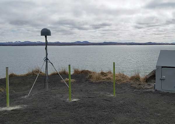
The Plate Boundary Observatory (PBO) network operated by UNAVCO (formerly the University NAVSTAR Consortium) is primarily designed to monitor long-term tectonic and volcanic deformation. However, it can also be used for GNSS-R applications. A new PBO station, AT01, was installed in May 26, 2018, in St. Michael, Alaska, which is designed to be suitable as a GNSS-R-based tide gauge with a clear and wide-open view toward the sea covering from 0° to 230° in azimuth (see FIGURE 2). The equipment at this site consists of a Trimble choke-ring geodetic antenna and a Septentrio PolaRx5 receiver that can receive not only GPS signals but also those of Galileo, with data recorded every 15 seconds.
FIGURE 2. The surrounding area of AT01 in St. Michael, Alaska: south view. (Photo: Authors)
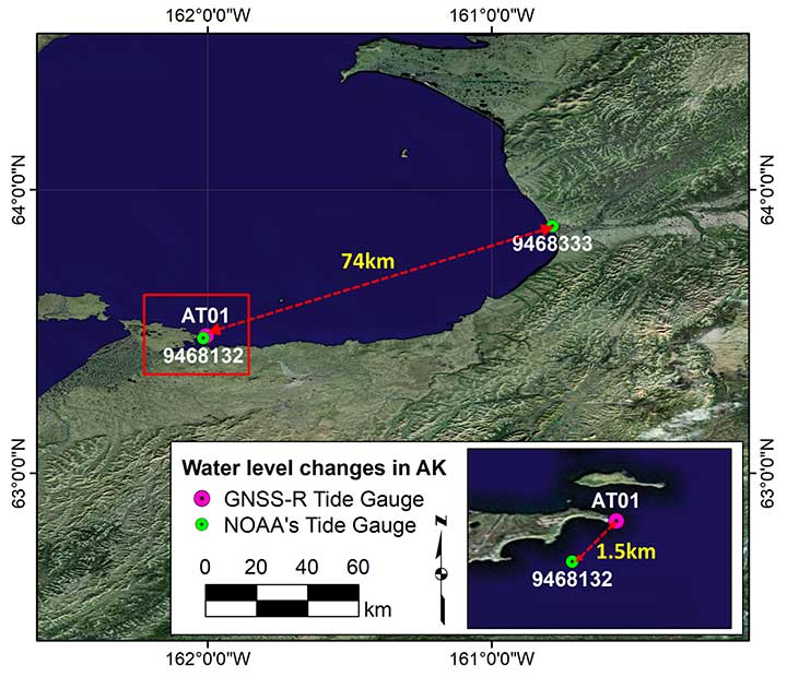
We have used this station to assess our technique using one month of SNR data from June 2018. It should be emphasized that not only GPS but also Galileo signals were processed, and the Center for Orbit Determination in Europe’s Multi-GNSS Experiment final orbit and satellite clock products were used to minimize the satellite orbit error. Additionally, NOAA tide gauge stations (9468132 and 9468333) were used for comparison and verification of the water levels measured from the GNSS-R-based tide gauge (see FIGURE 3).
FIGURE 3. Locations of AT01 and two NOAA tide-gauge stations (9468132 in St. Michael and 9468333 in Unalakleet). The red box represents the zoomed area at the bottom right. (Image: Authors)
The 9468132 tide gauge in St. Michael is the nearest tide gauge at approximately 1.5 kilometers from AT01. However, since it is not operational, NOAA only provides water-level predictions (just high and low tides) based on the harmonic constituents, not the actual measurements. On the other hand, the 9468333 tide gauge in Unalakleet is approximately 74 kilometers away from AT01. This makes it difficult to use the tide gauge as ground truth, but it does provide the actual sea-level measurements including any abnormal daily variations during the observation period. Therefore, we used the water-level predictions and measurements from both stations to validate the GNSS-R-based water-level measurements at AT01.
Determination of Water Level. The GPS and Galileo SNR data were independently analyzed using our in-house software package (written in MATLAB) using the following procedures.
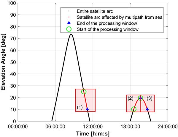
As a preprocessing step, each SNR data series was examined to filter out the signals reflected from other surfaces surrounding the antenna and to isolate the signals that were reflected by the sea surface. Since AT01 PBO station was installed to investigate the feasibility of its use as a GNSS-R-based tide gauge, the most effective azimuth and elevation ranges were given, which are 0° to 230° and 10° to 25°, respectively.
The azimuth and elevation angle ranges were applied, which effectively removed reflected signals from surfaces other than the sea surface. After identifying the SNR data affected by the reflection from the sea surface, the processing windows were dynamically determined by the continuous path and direction (ascending and descending) of the satellites, and the height of the sea surface was estimated using only a portion of the satellite arc contained within each processing window.
For example, FIGURE 4 shows the processing windows determined for the GPS satellite PRN 1 on June 1, 2018. The red dots in the figure show the parts of the satellite arcs affected by multipath from the sea surface. The data was divided into three processing windows due to the arc discontinuities and satellite path directions. It should be noted that only the processing windows with a data span of 30 minutes or longer were used for water level estimation. This minimum data span duration of 30 minutes was empirically determined by observing the probability of failure of the water -level calculation for shorter spans.
FIGURE 4. An example of the processing window determination for GPS satellite PRN 1 on June 1, 2018. (Image: Authors)
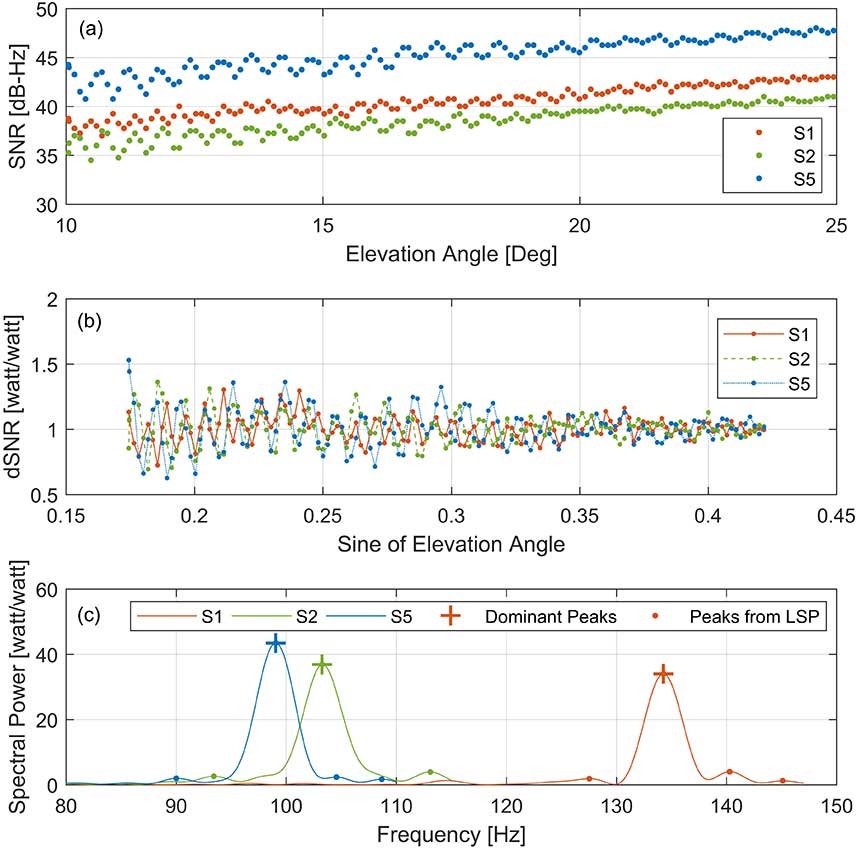
To isolate multipath effects from the SNR observation, we removed the trend in the SNR by a second-order polynomial fitting using only the portion of a satellite arc contained within each window. FIGURE 5 (b) shows the detrended SNR (dSNR) from FIGURE 5 (a), and the impact of the multipath is clearly identified in the form of the oscillation. As discussed earlier, the oscillation frequency is related to the antenna height above the sea surface. Accordingly, the dSNR data was analyzed through an LSP. As shown in FIGURE 5 (c), multiple peaks are founded from the LSP results of each dSNR series, and it is not easy to distinguish the frequency of the reflected signal from the sea level among these peaks.
Since multiple frequency signals from the same satellite must detect the same sea-level height, the final dominant peak was determined by checking the consistency of the resulting heights from each dominant peak among the multi-frequency signals. After that, the dominant frequency was converted to the antenna height above the reflection surface, which was then subtracted from the orthometric height of the antenna (the height above the geoid or, approximately, the height above mean sea level [MSL]) to refer the height of the instantaneous sea surface to MSL.
FIGURE 5. SNR data-analysis procedures with PRN 1 GPS on June 1, 2018: (a) The SNR data affected by the reflection from the sea surface, (b) detrended SNR data through a second-order polynomial, and (c) LSP results and dominant peaks of each frequency. (Image: Authors)
After analyzing all SNR data observed during one day, we carried out the reliability test of the retrieved sea levels to reject erroneous sea-level solutions.
RESULTS AND VALIDATION
The water-level changes from the GNSS-R-based tide gauge at St. Michael were compared to the independently predicted and measured sea levels from the neighboring St. Michael and Unalakleet tide gauges during June 1–30, 2018. Although the tide gauges are considered reliable ground truth, our experimental study must take into account the physical distance between the sites (about 1.5 and 74 kilometers from AT01, respectively) as well as the difference coming from the model versus the actual measurement.
In addition, a vertical offset between the data time series of the GNSS-R-based tide gauge and the standard tide gauges should be considered due to their different datums. Whereas the GNSS-R-derived sea level refers to a geodetic datum — namely the U.S. National Spatial Reference System (NAVD 88) — a standard tide gauge is highly localized with reference to a tidal datum such as local mean sea level. Generally, the difference between the geodetic and tidal datums is provided by NOAA, which allows us to convert between two vertical datums.
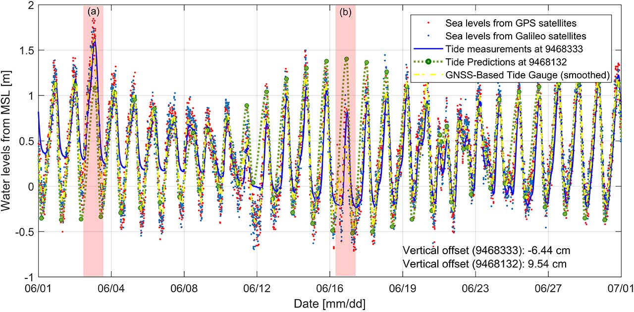
However, the vertical datum in Alaska has significant gaps in the spatially varying tidal information because of the difficulties of operating tide gauges there so that accurate information for datum conversion cannot be obtained. Therefore, the averages of the vertical differences were calculated (–6.44 centimeters for the St. Michael tide gauge and 9.54 centimeters for the Unalakleet tide gauge), which were then applied to each of the time series to make the comparisons. In fact, such a problem implies another advantage of a GNSS-R-derived tide gauge: it already returns a water-level height based on the terrestrial datum so that the datum of the land and the ocean can be consistently retained.
FIGURE 6 shows the sea level derived from the GNSS-based tide gauge measurements using GPS (red dots), Galileo (blue dots), the predicted sea level from the St. Michael tide gauge (green dots and lines) and measured sea level from the Unalakleet tide gauge (blue line).
FIGURE 6. Time series of sea level derived by GNSS-R-based tide gauge (AT01) in St. Michael, Alaska, during a month (red and blue dots for GPS and Galileo satellites, respectively; yellow dashed lines for the smoothed time series from two hours’ moving average filter) together with sea-level measurements from the Unalakleet tide gauge (blue solid line) and sea-level predictions from the St. Michael tide gauge (green dots for high- and low-tide predictions and green dashed line for interpolated predictions). (image: Authors)
The overall results show good agreement with the tide predictions at the nearby St. Michael tide-gauge station. It should be noted that the St. Michael tide gauge only provides high- and low-tide predictions so these were interpolated. However, some tidal characteristics not represented in the published predictions were also confirmed. In particular, as shown in the red-shaded segments of the time series marked (a) and (b) in Figure 6, larger and lower amplitudes than the tide predictions for the St. Michael tide gauge were identified on June 3 and 16, respectively.
These inconsistencies can be explained by the comparison with actual sea-level measurements at the Unalakleet tide gauge (solid blue line in Figure 6), which show very similar sea-level changes compared to those of the GNSS-R-based tide gauge. In addition, the overall larger amplitudes in the time series from the Unalakleet tide gauge can be explained by considering the fact that the amplitudes of the water levels vary along the coastline in Alaska and the Unalakleet tide gauge is approximately 74 kilometers from AT01.
To quantitatively investigate the agreement between the GNSS-R-based tide gauge and the standard tide gauges, we computed correlation coefficients. To ensure simultaneous data, the standard tide-gauge measurements and predictions were interpolated to the time tags of the GNSS-R-based time series. The correlation coefficients are 0.87 and 0.81 with the St. Michael and Unalakleet tide gauges, respectively.
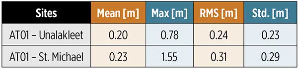
The statistical analysis of the comparison result is summarized in TABLE 1. The mean and maximum values were computed using the absolute sea-level differences. From the results, it could be established that the GNSS-R-derived sea level shows better agreement with actual sea-level measurements at the Unalakleet tide gauge even though it is approximately 74 kilometers away from AT01.
Table 1 Statistical analysis of the sea-level differences between the GNSS-R-based tide gauge (AT01) and the standard tide gauges (Unalakleet and St. Michael).
Spectral analysis was additionally conducted to validate the sea levels from the GNSS-R-based tide gauge. Because the St. Michael tide gauge does not provide actual measurements (only predictions), only the Unalakleet tide gauge was used in the spectral comparison. A fast Fourier transform (FFT) was applied to convert the time series of the sea levels to the frequency domain.
The GNSS-R-based tide gauge showed good agreement with the Unalakleet tide gauge overall. In addition, from the corresponding spectral analysis results, we were able to find meaningful harmonic constituents, M2, K1 and O1. The harmonic constituents estimated from the sea-surface measurements of the GNSS-R-based tide gauge have amplitudes most similar to the published harmonic constituents of the nearest St. Michael tide gauge, although the difference in amplitudes of the three harmonic constituents averages 12.3 centimeters.
In fact, the Unalakleet tide gauge also does not exactly match the amplitude of the estimated harmonic constituents and the published harmonic constituents. But by summarizing the corresponding results, we can conclude that the harmonic constituents estimated from the GNSS-R-based tide gauge are reliable.
As mentioned earlier, in our study, we estimated the water-level change by using GPS and Galileo satellite signals to overcome the degradation of GNSS performance due to the satellite geometry in the Arctic. The smoothed time series, calculated from a moving-average filter of two-hour intervals, is shown in Figure 6 (yellow dashed lines). The time series of sea level derived by the GNSS-R-based tide gauge during the whole month were used as ground truth for evaluating the accuracy.
This was done because the Unalakleet tide gauge is approximately 74 kilometers away from AT01 and the St. Michael tide gauge does not provide actual measurements, making it difficult to use as ground truth. As a result, the sea levels determined using the Galileo and GPS signals showed very similar accuracy with an average difference of 0.11 meters. Therefore, even if Galileo is additionally used, the estimated final water levels were at a similar level of accuracy.
However, the number of water-level observations dramatically increased (approximately doubled) when GPS and Galileo signals were both involved, even though the number of Galileo satellites is fewer than the number of GPS satellites. This is because Galileo transmits on five frequencies while GPS transmits on just three, so we can achieve more robust solutions by including Galileo.
We investigated how adding Galileo satellites changes the temporal resolution of the final sea-level measurements. At this time, several sea-level measurements pointing to the same epoch (such as sea levels from several frequency observations of the same satellite arc) were considered as one measurement for the time interval computation.
Overall, sea-level measurements using only Galileo satellites show lower temporal resolution compared to GPS satellites alone, with a mean time interval of 48.97 minutes because Galileo is not fully operational yet and fewer satellites are available. However, combining GPS and Galileo satellites to the sea-level analysis significantly increased the time resolution.
When only GPS satellites were used, the maximum time interval between two water-level measurements was greater than 3 hours, while the maximum time interval was shortened to about 1.5 hours when Galileo satellites were included in the water-level measurement.
However, even if both GPS and Galileo satellites were used, the average time interval was still 14.1 minutes, which is considerably longer than the time resolution of the standard tide gauge of 6 minutes. The lower time resolution of a GNSS-R-based tide gauge is explained by the limited ranges (azimuth and elevation angle ranges of 0° to 230° and 10° to 25°, respectively) toward the ocean at station AT01. It means the time resolution can be improved by securing a wider view of the ocean from the GNSS-R-based tide gauge.
SUMMARY AND CONCLUSION
The purpose of our study was to evaluate and verify the feasibility of using GNSS-R for sea-level monitoring in the Arctic. We used data from a GNSS station in St. Michael, Alaska, and applied an advanced algorithm that accurately determines sea levels through the comparisons of results from multiple GNSS signals along with an effective filtering procedure. Our results were validated through comparisons with measurements and predictions from nearby standard tide gauges.
From the corresponding analysis, we could confirm that the GNSS-R technique overcomes the limitations of standard tide gauges in the Arctic and successfully estimated the sea-level change in St. Michael, Alaska. The results from this study show many promising applications for a GNSS-R-based tide gauge in the Arctic, such as tsunami and flood monitoring and tidal datum determination.
In future studies, additional research should be conducted on how well the GNSS-R-based tide gauge can operate in extreme conditions such as low temperatures, wind gusts, storms, and snow. And, for further improvement of the temporal resolution of the technique, all active GNSS constellations including GPS, GLONASS, Galileo, and BeiDou should be included — that will certainly improve the temporal resolution and also potentially improve the accuracy and reliability. It would be also worth studying the spatial variations of sea-level changes by investigating the specular reflection points of GNSS multipath signals.
ACKNOWLEDGMENTS
This article is based on the paper “Monitoring Sea Level Change in the Arctic Using GNSS-Reflectometry” presented at ION ITM 2019, the 2019 International Technical Meeting of The Institute of Navigation, Reston, Virginia, Jan. 28–31, 2019.
SU-KYUNG KIM is a graduate research assistant at Oregon State University in Corvallis, Oregon. She received her M.Sc. in geoinformation engineering from Sejong University in Seoul, South Korea, in 2013. Her research interests are focused on sea-level change monitoring and crustal deformation studies using GNSS.
JIHYE PARK is an assistant professor of geomatics at Oregon State University. She holds a Ph.D. in geodetic science and surveying from The Ohio State University in Columbus, Ohio. Her research interests include GNSS positioning and navigation, GNSS reflectometry, ionospheric and tropospheric monitoring for natural hazards and artificial events, and other geospatial-related topics.
FURTHER READING
Authors’ Conference Paper
“Monitoring Sea Level Change in the Arctic Using GNSS-Reflectometry” by S.-K. Kim and J. Park in Proceedings of ION ITM 2019, the 2019 International Technical Meeting of The Institute of Navigation, Reston, Virginia, Jan. 28–31, 2019.
Pioneering Work by Manuel Martin-Neira
“The PARIS Concept: An Experimental Demonstration of Sea Surface Altimetry Using GPS Reflected Signals” by M. Martín-Neira, M. Caparrini, J. Font-Rossello, S. Lannelongue and C.S. Vallmitjana in IEEE Transactions on Geoscience and Remote Sensing, Vol. 39, No. 1, 2001, pp. 142–150, doi: 10.1109/36.898676.
“Coastal Sea Level Measurements Using a Single Geodetic GPS Receiver” by K.M. Larson, J.S. Löfgren and R. Haas in Advances in Space Research, Vol. 51, No. 8, 2013, pp. 1301–1310, doi: 10.1016/j.asr.2012.04.017.
“Monitoring Coastal Sea Level Using Reflected GNSS Signals” by J.S. Löfgren, R. Haas and J.M. Johansson in Advances in Space Research, Vol. 47, No. 2, 2011, pp. 213–220, doi: 10.1016/j.asr.2010.08.015.
“Three Months of Local Sea Level Derived from Reflected GNSS Signals” by J.S. Löfgren, R. Haas, H.-G. Scherneck and M.S. Bos in Radio Science, Vol. 46, No. 6, 2011, RS0C05, doi:10.1029/2011RS004693.
“Determination of Water Level and Tides Using Interferometric Observations of GPS Signals” by K.D. Anderson in Journal of Atmospheric and Oceanic Technology, Vol. 17, No. 8, 2000, pp. 1118-1127, doi: 10.1175/1520-0426(2000)017<1118:DOWLAT>2.0.CO;2.
Earlier Innovation Columns Dealing with GNSS Refectometry
Tides, Surges and Mean Sea-Level by D. Pugh, published originally by J. Wiley & Sons, Chichester, U.K., 1987, reprinted with corrections in 1996 and subsequently issued in e-print form by NERC Open Research Archive.
Random Sample Consensus
“Random Sample Consensus: A Paradigm for Model Fitting with Applications to Image Analysis and Automated Cartography” by M.A. Fischler and R.C. Bolles in Communications of the ACM, Vol. 24, No. 6, 1981, pp. 381–395, 10.1145/358669.358692.
The Official Journal of the European Union (EU) will publish a funding opportunity in the near future for a GNSS “Advanced Interference Detection and Robustness Capabilities System,” according to officials familiar with the project.
Advance notice of this procurement was first given in August of last year, with an award projected for the first quarter of 2019. Some observers have speculated that the procurement delay was related to a change in how the final system is envisioned. The current version of the notice asks for a crowdsourcing, software and networked-based solution.
The advance notice calls for the vendor to both establish the system and operate it.
The purpose of the present tender is to establish a new mechanism to detect interference at receiver and antenna level based on crowdsourcing and sharing information coming from any user (individuals or associated ones) and run the service for a period of two years.
While for many “crowdsourcing” suggests the participation of large numbers of individuals, this will likely not be part of the scheme. Speaking to a government advisory board, Jean Yves Courtois, CEO at Orolia, said that battery drain on cell phones would prevent this from being practical. “Privacy concerns would also be an issue,” he said. Each individual would have to affirmatively agree to have their location information used continuously. This additional administrative burden would be significant.
Much easier and preferable would be using Information from already deployed networks of fixed receivers, such as base stations. Unchanging locations and existing network connections make the engineering easier and thorny privacy concerns would be minimized. These ideas are also reflected in the current version of the advance notice:
The activity shall also focus on identifying and engaging users (such as entities currently monitoring vast networks of devices integrating GNSS receivers) by means of an appropriate enrolment scheme ensuring the provision of the data. The design of the system shall ensure that the sensitivity of the data (GNSS vulnerabilities) is always protected.
Crowdsourcing and collating such information is seen by many in industry as a relatively straight-forward engineering problem. Representatives from Orolia and Microsemi, for example, included ideas about crowdsourcing disruption data in recent presentations to the U.S. PNT Advisory Board. Both agreed, though, that there are few commercial incentives to do such work without a government customer.
It is perhaps not a surprise that the EU is taking the lead in this field while other GNSS providers seem to have little interest.
Unlike GPS, GLONASS and BeiDou, which are first and foremost national security systems, Europe’s Galileo was built and is operated by a civil organization focusing on economic and civil benefits. Interference with signals directly undercuts these benefits and can be easily seen in direct economic costs.
Many European countries are using GNSS for road tolling, for example. Small GNSS jammers are easy to acquire off the internet and their illegal use is likely costing nations millions of euros in lost tolls each year. Without the ability to regularly detect, sanction, and deter this activity financial losses will continue to mount.
The interference with tolling problem is not specifically addressed in the EU’s advance notice. It may well be that tolling authorities and others will be expected to install their own application specific interference detectors and then encouraged to link them to the EU backbone and database.
The European Commission has been aware of this vulnerability for some time. In 2015 it contracted with Nottingham Scientific Ltd. in the UK to lead a multi-nation team and assess the extent of the problem.
The STRIKE3 project was in operation from February 2016 to January 2019. Its goals were to sample and classify interference events, recommend a standard event reporting scheme, and assess the vulnerability of different types of GNSS receivers.
The project’s sampling activity in 23 different countries detected nearly 500,000 interference events. Of these, 59,000 were classified as deliberate attempts to disrupt GNSS signals.
Within the deliberate events the STRIKE3 team were able to identify about 300 jammer “families,” according to Mark Dumville, Co-Founder and Director at Nottingham Scientific. Along with the jammers they were able to classify into groups, there were “some very interesting outliers,” Dumville said. “These are likely evidence of jammer technology continuing to develop and evolve.”
STRIKE3 is viewed as a very successful project by most everyone in the international PNT community, and certainly within the EU, according to officials.
The upcoming announcement and future establishment of an on-going interference detection capability are some of the next logical steps to better securing Europe’s PNT services.
UAVOS has added the R22-UV unmanned helicopter to its agriculture unmanned aircraft portfolio for spraying for diseases, weed and pest control, and vegetation control.
The R22-UV is a manned Robinson-22 helicopter converted by UAVOS to an unmanned aircraft. (Photo: UAVOS)
The Agro-Drone R22-UV is equipped with a specially developed utility to deliver liquid chemicals — the spray system Simplex model 222.
The R22-UV drone is provided with a 100-liter tank for chemicals and can stay airborne for two hours. Weight of the system is 42 kilograms, boom span is 7 meters, and swath width is 14 to 16 meters.
UAVOS listed several advantages that could maximize the value of such a heavy UAV for farmers:
The R22-UV can be operated in the regions without airfields, under severe weather conditions and during night-time, in conditions with a high probability of risk for the pilot.
UAVs are excellent for operations in conditions of high humidity, where the use of ground equipment is impossible or difficult. Unlike heavy machinery, which cannot go into a field immediately after a heavy rain, UAV has no impact on the ground. Drone sprayers don’t touch the ground so there will be less soil compaction. This is when heavy machinery like tractors roll over the soil, pressing it down and damaging it. Farmers can fix this with plowing, but it can be harmful to the soil over a long period of time.
UAV implementation eliminates manual spraying with backpack sprayers, so workers don’t come into contact with hazardous chemicals.
UAVs also enable growers to spray their crops precisely and at will, which is critical for fighting herbicide-resistant weeds. Spraying is better. The rotor of an agricultural drone produces a huge downward rotation force, which promotes the pesticide droplets to penetrate the crop from top to bottom, which is conducive to the pesticide droplets evenly scattered in all parts of the plant, so that the spraying is accurate.
Unmanned aircraft can be used for spot spraying weeds with herbicides and are useful for spraying crops with pesticides. A spot-oriented approach based on preliminary analysis of digital images from robot cameras minimizes the cost of agrochemicals, reducing the chemical impact on soil, water, culture and, ultimately, on the consumer’s body, while achieving higher results of crop cultivation than with traditional approaches. The aircraft can be set on a predetermined GPS-defined route to fly over a field, dropping doses of pesticides, herbicides and fungicides as it flies.
“Precision agriculture is based on the use of valuable metrics to make farmers’ crop management efficient and optimized,” said Aliaksei Stratsilatau, CEO of UAVOS. “Validating-of-damage reports used to be on paper. So, unmanned aircraft help our customers to validate the veracity of reports so that we could come up with a comprehensive solution. Generally, agriculture is very complex and there are a lot of problems, but there are solutions available through the new technology.”
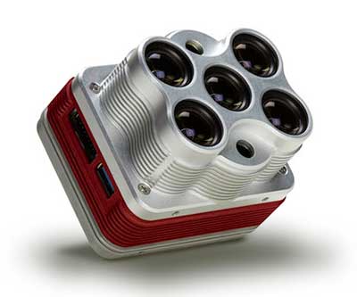
The Altum is a 3-in-1 sensor that combines thermal, high-resolution and multispectral imaging capabilities. (Photo: MicaSense)
The Altum sensor, offered by MicaSense, is designed for professional-grade agricultural drone mapping by enterprise and academic researchers. The Altum captures synchronized multispectral and thermal imagery, enabling aligned outputs for advanced analytics.
Altum’s multispectral imagers are the highest resolution integrated multispectral solution available for drones, allowing for detailed RGB outputs and advanced crop classifications.
Whereas before they had to fly multiple flights with multiple sensors, researchers, growers and service providers can now capture data for plant health, water stress mapping, phenotyping and more in one flight, with one sensor.
“The Altum design resulted from experience developing advanced analytics and understanding needs for advanced research,” said Justin McAllister, CTO and co-founder of MicaSense. “We realized the market is limited by time and cost constraints of owning multiple sensors and flying multiple passes over the same field. The goal of Altum is to simplify the workflow, and with synchronized capture, to provide results that can be correlated and quantified more easily.”
Altum includes MicaSense’s standard five-band configuration of multispectral bands (red, green, blue, near-infrared and red-edge) and an integrated Lepton radiometric thermal longwave infrared sensor from FLIR Systems, providing temperature measurement for every pixel of the scene for additional crop data and optimization.
https://youtu.be/Kdim4uol7S4
Expandable high-capacity USB 3.0 storage allows users to fly longer and cover more area without landing to swap storage. In addition, advancements in image capture rate enables faster flight speeds.
Users can process Altum data with industry standard software like Agisoft and Pix4Dmapper to generate an aligned, radiometrically calibrated six band (R, G, B, RE, NIR, T) geotiff, or access the raw data from Altum to process data themselves.
Included with Altum is DLS 2, the patent-pending next generation of the MicaSense Downwelling Light Sensor (DLS). DLS 2 allows for a more streamlined integration as it combines both the DLS and GPS into one product. In addition, through proprietary MicaSense technology, the DLS 2 will offer significantly better calibration for changing light conditions and better measurements over time.
Integrated solutions
Altum’s multiple interface options and open API gives users the ability to utilize Altum on a variety of platforms. In addition to the DJI SkyPort integration, Altum is integrated with drone offerings from the following companies (with more to come):
North America: Drone Nerds (U.S.), BirdsEyeView Aerobotics (U.S)., OmniView Tech (Canada), Sky Flight Robotics (U.S.), Blue Skies Drone Rental (U.S.)
Europe: 3D Target (IT), Globe Flight (DE), C-Astral (SI), Droneparts.de (DE), Ecobotix (DK), NaviGate (PL), Quantum Systems (DE)
DJI Payload SDK Program: Altum and RedEdge-MX for DJI M200 Series
Through DJI SkyPort, MicaSense is able to provide seamless integration of its specialized sensors with DJI’s powerful line of enterprise drones, resulting in the MicaSense Altum and RedEdge-MX solutions. This provides users a high-quality drone and sensor combination they can rely on to capture quality data every time – with virtually no set-up time.
The DJI SkyPort integration for Altum and RedEdge-MX features plug-and-play integration for Altum and RedEdge-MX right out of the box, including power and quick connect/disconnect, and enhanced light calibration with MicaSense DLS 2.
“Solutions like the MicaSense Altum and RedEdge-MX demonstrate the value of integrating specialized industrial payloads to DJI’s powerful drone platforms,” said Jan Gasparic, head of Enterprise Partnerships at DJI. “By collaborating with solution providers, we are expanding the benefits of drone technology to more and more industries. In the case of agriculture, a specialized suite of sensors and more advanced level of analytics can truly bring tangible value to business workflows and decision making today.”
The Altum and SkyPort enabled RedEdge-MX and Altum are available today through the MicaSense website.
The new GSAGNSS Market Report is now available for download. The report provides a comprehensive overview of the GNSS market and the global industry, as well as a focus on EGNSS differentiators and synergies with Copernicus, according to the publisher, the European GNSS Agency (GSA).
Areas covered include:
A general overview of the GNSS market and a global industry overview.
Analysis of macro-trends affecting GNSS, including climate change and the circular economy, big data, artificial intelligence, the silver economy, cyber security and the sharing economy.
A review of the main GNSS market segments in detail, including trends and developments, forecasts for future shipments, revenues and the GNSS installed base, and a look into GNSS user requirements.
GNSS in Space. This year, the report features the “Editor’s Special: GNSS for NewSpace,” a section that introduces GNSS receivers in satellites and their relation to the evolving space sector.
GNSS market monitoring is a key activity of the GSA. Market monitoring supports GNSS stakeholders in their planning and decision-making, and offers a clear tool to understand GNSS trends and evolutions.
Since its launch in 2010, the GSAGNSS Market Report has become the go-to-source for information on the dynamic, global GNSS market segments and applications.
Quectel Wireless Solutions has completed a data call over its 5G millimeter wave (mmWave) module that fully complies with 3GPP Release 15 5G NR standards.
The 5G data call on Sept. 25 was made over a Quectel RM510Q-GL 5G module based on Keysight’s 5G testing device in a lab, paving the way for the upcoming 5G mmWave field tests and commercial deployment of 5G internet of things (IoT) projects.
In addition, the move is a testament to Quectel’s leadership in 5G research and development capability and IoT innovations.
Tailored for IoT/eMBB (enhanced mobile broadband) applications, Quectel RM510Q-GL features the Snapdragon X55 5G modem and supports mmWave and sub-6 GHz frequencies in both 5G standalone (SA) and non-standalone (NSA) operations.
The M.2 module covers nearly all the mainstream carriers worldwide. Designed backward compatible with LTE-A and 3G networks, RM510Q-GL integrates multi-constellation GNSS receiver, eSIM, as well as high-speed interfaces such as USB 3.1 and PCIe 3.0, which make it suitable for globally deployed mobile devices including Always Connected PCs (ACPC), industrial PDAs, mobile gateways and more.
AsusTek Computer Inc., a Taipei-based multinational computer company, is planning to use RM510Q-GL for its next-generation 5G mmWave laptops, according to Quectel. Leveraging its industry leading 5G modules and local technical support, Quectel will accelerate the time-to-market for AsusTek to enhance its competitiveness in the 5G era.
Quectel will showcase commercial 5G modules at the Qualcomm 5G Summit in Barcelona, Oct. 14-16, and MWC Los Angeles (Booth 1236), Oct. 22-24.