Author: Tracy Cozzens

  • Research Roundup: Navigating urban canyons

    Research Roundup: Navigating urban canyons

    Tall buildings block GNSS signals, making satellite navigation in urban canyons very challenging. (Photo: RoschetzkyIstockPhoto/iStock/Getty Images Plus/Getty Images)
    Tall buildings block GNSS signals, making satellite navigation in urban canyons very challenging. (Photo: RoschetzkyIstockPhoto/iStock/Getty Images Plus/Getty Images)

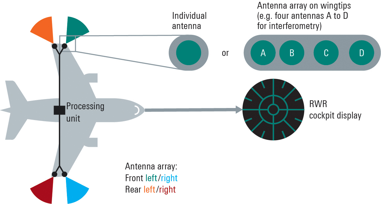
    GPS positioning for navigation and mapping is challenging in urban environments, where GPS signals often are blocked by tall buildings. The following three papers — to be presented at the Institute of Navigation (ION) GNSS+ conference Sept. 19–23, 2022 — explore ways to solve that problem. The full papers will be available at www.ion.org/publications/browse.cfm following the conference.

    ALGORITHMS FOR URBAN MAPPING

    In this work, the authors use an urban environment model incorporating visibility predictions and remote-sensing techniques, which they tested in a sensor-equipped vehicle in Denver. They use an interacting multiple model (IMM) filter that uses extended Kalman filters to build and verify a map of the signal environment in an urban-canyon setting. The techniques will give ground-vehicle operations the ability to plan for blocked and delayed signals for global path planning.

    Zeller, Emma; Strandjord, Kirsten, University of Minnesota; and Wang, Pai, Shanghai Jiao Tong University; “Algorithms for Mapping the Urban Signal Environment for Navigation of Ground Vehicle Operations.”

    ADDING VISUAL TO GNSS/INS

    GNSS real-time kinematic (GNSS-RTK) positioning is a key technology for surveying and mapping applications. To extend the capability of GNSS in difficult environments, a tight coupling between GNSS-RTK and an inertial navigation system (INS) can greatly improve the results. If the time spent in a GNSS outage is too long or if the kinematic of the survey is too weak, the GNSS/INS solution can be compromised with high navigation errors, ultimately making it impossible to align the heading angle at initialization.

    This paper presents an innovative solution to overcome GNSS/INS limitations, minimizing system complexity by using a tightly coupled GNSS/INS solution with a monocular visual inertial SLAM system. This solution is capable of initialization in a few seconds and is very reliable in the long term. This vision/INS/GNSS coupling increases the overall RTK fix rate and broadens the availability of high-precision navigation solutions under challenging conditions.

    Bénet, Pierre; Saussay, Brice; Saidani, Mourad; and Guinamard, Alexis; SBG Systems; “Tightly Coupled Inertial Visual GNSS Solution: Application to LIDAR Mapping in Harsh and Denied GNSS Conditions.”

    USING 3D BUILDING MODELS

    To solve the urban-navigation challenge, the authors propose using a 3D building model to assist GNSS positioning. This type of algorithm is named the 3D building model aided GNSS (3DMA GNSS). It can predict measurement errors and the visibility of the satellites, as line-of-sight or non-line-of-sight. The solution is then derived from the likelihood of the observed and predicted measurements over candidate locations.

    The authors propose an innovative method for evaluating the reliability of building models based on the awareness of sky visibility in a specific geographic context. Sky visibility estimation is improved with use of a support vector machine regression and considering low-Earth-orbit (LEO) constellations. The real-time sky visibility could present the update of the surrounding buildings, whereas the predicted sky visibility based on the existing building models remains unchanged. Making use of this inconsistency, the authors could identify areas with the updated building. Additionally, the impacts of the building update monitoring on the 3DMA GNSS are evaluated in an urban canyon.

    Xu, Hao-Sheng and Hsu, Li-Ta; Department of Aeronautical and Aviation Engineering, The Hong Kong Polytechnic University; “Urban Buildings Update Monitoring Based on Sky Visibility Estimation using GNSS and LEO.”

  • Editorial Advisory Board Q&A: The need for correction services

    Will GPS modernization and improvements in GPS receivers and antennas reduce or even eliminate the need for correction services for most applications?

    Headshot: Julian Thomas
    Julian Thomas, managing director, Racelogic


    “For most applications, I think the answer is yes, the need for correction services will be reduced. When you can get <1m without external corrections, the majority of conventional accuracy requirements are fulfilled. However, increases in accuracy always open up new applications for GPS, so correction services will still be required.”
    — Julian Thomas
    Racelogic


    Headshot: Miguel Amor
    Miguel Amor, chief marketing officer, Hexagon’s Autonomy & Positioning Division

    “Correction services will continue to be in demand for those markets and applications requiring precision and accuracy below a few inches, 2-3 sigma confidence levels and high reliability, availability and integrity. While ionospheric errors have been low in the past 15+ years, correction services will also provide ionospheric models beneficial in periods of higher activity. Even as there are improvements in user equipment and signal modernization, the demand for correction services will increase in line with these improvements and new functionalities to enable more markets and applications worldwide.”
    — Miguel Amor
    Hexagon’s Autonomy & Positioning Division

  • Reliable navigation with interference-free GNSS signals

    Reliable navigation with interference-free GNSS signals

    By Markus Irsigler and Sebastian Kehl-Waas

    Interference-free GNSS signals are essential for more than just military vehicles and aircraft. Anti-jam systems usually suppress signals from interference sources by means of spatial filtering.

    These solutions can likewise be used to protect satellite navigation signals for autonomous driving and flying against interference signals. To allow GNSS receivers to detect interference sources and suppress transmitted interference signals, they must be designed as multichannel systems.

    This way the direction of the interference signal can be determined using phase-coherent signal processing of signals from multiple antennas, and the interference can be suppressed. Rohde & Schwarz offers a solution for the verification of interference immunity and interference suppression.

    FIGURE 1a. The GNSS antenna in the example on the left has only one element, so its characteristic cannot be modified. A sufficiently strong interference signal can prevent the receiver from processing the GNSS signals, making satellite-based navigation impossible.
    FIGURE 1a. The GNSS antenna in the example on the left has only one element, so its characteristic cannot be modified. A sufficiently strong interference signal can prevent the receiver from processing the GNSS signals, making satellite-based navigation impossible.
    FIGURE 1b. In contrast to the individual antenna, the characteristic of the antenna array can be modified by combining and weighting the received signals. The interference signal is suppressed at its angle of arrival, and the GNSS signals can be received. A disadvantage is that GNSS signals from the same direction as the interference signal are also suppressed.
    FIGURE 1b. In contrast to the individual antenna, the characteristic of the antenna array can be modified by combining and weighting the received signals. The interference signal is suppressed at its angle of arrival, and the GNSS signals can be received. A disadvantage is that GNSS signals from the same direction as the interference signal are also suppressed.

    Multi-channel receivers can simultaneously process signals from multiple distributed antennas or from an antenna array. This is useful for determining the direction of incoming signals by means of signal analysis, and for adjusting the antenna pattern so that undesired signals are suppressed. For GNSS-based position determination, this means that signals from global navigation satellite systems (GNSS) can be strengthened and jamming or spoofing signals originating from the ground or the air can be suppressed. Up to now this technology has primarily been used for military applications, but in the future it can also make an important contribution to robust navigation for autonomous driving or flying. Typical interference sources in this regard are harmonics of transmitters in the vicinity, tactical air navigation (TACAN) signals, DME air navigation signals for civil aviation, and LTE signals. Another factor is the growing popularity of so-called personal privacy devices (PPD), which are GNSS jammers that radiate narrowband or broadband signals to disrupt GNSS localization. A new solution from Rohde & Schwarz enables comprehensive testing of the resistance of GNSS receivers to interference signals, if necessary in a realistic hardware-in-the-loop (HIL) environment.

    Multi-Channel GNSS Receivers for Interference Suppression

    GNSS receivers often use controlled reception pattern antennas (CRPA) to suppress undesired signals. These antennas consist of an antenna array and a signal processing unit. The connected antennas are generally arranged in a strict geometric pattern to achieve full coverage of all possible signal directions. The overall receive characteristic of the antenna array can be altered by suitable weighting of the signals from the individual antennas in the signal processing unit (Fig. 1). This way, interference signals can be specifically blanked out (nulling) or the required GNSS signals can be amplified at their angle of arrival (beamforming). A combination of these two methods is also possible. The antenna arrays typically consist of four to seven elements. The number of interference signals that can be simultaneously suppressed increases with the number of elements.

    FIGURE 2. A four-channel GNSS test system consisting of two R&S SMW200A vector signal generators and an R&S SMA100B analog signal generator for the LO signal (left). The vector network analyzer is used to calibrate the overall system at a user-selectable reference plane in terms of amplitude, phase and propagation time.
    FIGURE 2a. A four-channel GNSS test system consisting of two R&S SMW200A vector signal generators and an R&S SMA100B analog signal generator for the LO signal (left). The vector network analyzer is used to calibrate the overall system at a user-selectable reference plane in terms of amplitude, phase and propagation time.
    FIGURE 2. A FIGURE 2b. A four-channel GNSS test system consisting of two R&S SMW200A vector signal generators and an R&S SMA100B analog signal generator for the LO signal (left). The vector network analyzer is used to calibrate the overall system at a user-selectable reference plane in terms of amplitude, phase and propagation time.four-channel GNSS test system consisting of two R&S SMW200A vector signal generators and an R&S SMA100B analog signal generator for the LO signal (left). The vector network analyzer is used to calibrate the overall system at a user-selectable reference plane in terms of amplitude, phase and propagation time.
    FIGURE 2b. A four-channel GNSS test system consisting of two R&S SMW200A vector signal generators and an R&S SMA100B analog signal generator for the LO signal (left). The vector network analyzer is used to calibrate the overall system at a user-selectable reference plane in terms of amplitude, phase and propagation time.

    Test System Requirements

    Rohde & Schwarz offers a test system for GNSS receivers that use CRPAs. First, it acts as a multichannel GNSS simulator that considers all aspects of a satellite navigation system. It must be able to generate the signals of all standard satellite navigation systems in all GNSS frequency bands, with attention to correct satellite orbits, signal propagation characteristics and realistic modeling of the dynamically changing receive environment. Configuration of the antenna array in terms of geometry and the receive characteristics of the individual antennas also must be included.

    Simulating the Interference Signals

    Second, the system can simultaneously generate jamming or spoofing signals in order to test the interference suppression functions of the device under test (DUT). A second, identical test system is necessary for freely definable configuration of interference sources with very high transmit power. Here the R&S Pulse Sequencer software assists in the definition of complex interference scenarios. The scenarios cover requirements such as long simulation times, moving interference sources and GNSS receivers, user-defined antenna patterns and antenna scans. In addition, the software calculates the correct amplitude, phase angle and propagation time of the signals as a function of signal frequency, antenna arrangement, and the positions of transmitters and receivers in three-dimensional space for each individual antenna element. Signal generation is handled by the R&S SMW200A high-end vector signal generator.

    For the tests, the required GNSS signal as well as the unwanted interference signals must be generated for each antenna input of the GNSS receiver. In order to test a CRPA receiver with four antenna inputs, this means that four signal sources are needed to generate the GNSS signals and an additional four signal sources are needed to generate the interference signals. Fig. 2 shows a pair of test systems that can be used to generate coupled GNSS signals and interference signals for a four-channel CRPA receiver.

    Calibration Against the DUT

    In order to correctly simulate the directions of the satellite signals and the interference signals, the test systems must be calibrated at the RF interface to the DUT with regard to amplitude, phase and propagation time. This means that the amplitude, phase and propagation time differences between the individual RF paths, resulting for example from cables or RF components, must be compensated. The vector signal generators of each system are phase coherently linked using suitable synchronization. A high-end R&S SMA100B analog signal generator in each system provides the shared LO signal.

    Using the R&S RF Ports alignment software, the complete system can be calibrated at any desired reference plane with regard to amplitude, phase and propagation time, so that the properties of the test system do not corrupt the simulated signal differences between the individual antennas. The required measurements are performed with a vector network analyzer.

    It is not necessary to calibrate the two test systems relative to each other. For the simulation of realistic scenarios, it is sufficient to run the GNSS and interference source simulations at the same time, since in the real world there is usually no correlation between GNSS satellites and interference sources.

    FIGURE 3. Aircraft with a multichannel radar warning system consisting of multiple receive channels, a central processing unit and a display.
    FIGURE 3. Aircraft with a multichannel radar warning system consisting of multiple receive channels, a central processing unit and a display.

    Integration in an HIL Environment

    The GNSS test system also can be embedded in a hardware-in-the-loop (HIL) environment. In this case a computer streams the motion profile of the GNSS receiver under test, with position, speed, acceleration and vehicle attitude, to the test system at a high data rate. The test system then generates the corresponding satellite navigation signal in real time. This requires very high update rates and low latencies.

    Summary

    Multichannel GNSS CRPA receivers considerably improve the navigation of ground vehicles and aircraft of all kinds. With the new Rohde & Schwarz test system, realistic multi-channel test signals can be generated for both GNSS simulation and interference simulation. For tests in an HIL environment, motion data also can be streamed to the GNSS test system.

  • Collins Aerospace launches M-code-compatible system for ground vehicles in Europe

    Collins Aerospace launches M-code-compatible system for ground vehicles in Europe

    Photo: Collins Aerospace
    Photo: Collins Aerospace

    Collins Aerospace has introduced NavHub-200M, a vehicle navigation system for the international market compatible with military code (M-code) receiver technology. The NavHub-200M is not controlled by the International Traffic in Arms Regulations (ITAR).

    Collins Aerospace made the announcement at Eursatory 2022, taking place June 13-17 in Parsis.

    NavHub-200M’s message formats and signal modulation techniques ensure faster and more accurate performance for ground vehicles on the connected battlespace, the company said.

    NavHub-200M provides assured positioning, navigation and timing (APNT) capabilities while improving overall resistance to existing and emerging threats to GPS, such as jamming and spoofing.

    “With GPS-based Selective Availability Anti-Spoofing Module (SAASM) receivers set to become obsolete, it is critical that M-Code receiver technology is made available to ground forces around the world as quickly as possible so they can trust that the signals they receive in a fast-moving, hostile environment are accurate and actionable,” said Ryan Bunge, vice president and general manager, Communication, Navigation and Guidance Solutions for Collins Aerospace. “Our NavHub-200M provides an improved resistance to jamming and interference, as well as advanced security features to prevent unauthorized access or exploitation.”

    NavHub-200M also includes the open interface standards and sensor-fusion capabilities required for a GNSS upgrade path, such as that for Europe’s Galileo constellation, as well as the ability to interface with key vehicle sensors such as the inertial measurement unit (IMU) and odometer, among others.

    Collins, a leader in APNT solutions for ground platforms, has delivered more than 10,000 navigation systems to military armed forced around the world.

    Attendees at Eurosatory can learn more by visiting Collins Aerospace at booth number C523.

  • Amazon to start drone delivery service in California

    Amazon to start drone delivery service in California

    Photo: Amazon
    Photo: Amazon

    Amazon customers in Lockeford, California, will be among the first to receive Prime Air drone deliveries in the United States, later this year. According to an Amazon blog, the company has been working for almost a decade to make it a reality.

    Customers in Lockeford will see Prime Air-eligible items on Amazon. They will place an order as usual and receive an estimated arrival time with a status tracker for their order. For these deliveries, the drone will fly to the designated delivery location, descend to the customer’s backyard, and hover at a safe height. It will then safely release the package and rise back up to altitude.

    Customer feedback about Prime Air, with drones delivering packages in their backyards, will help Amazon create a service that will safely scale to meet the needs of customers everywhere, according to the company.

    “Lockeford residents will soon have access to one of the world’s leading delivery innovations,” said California State Assemblyman Heath Flora, whose district includes Lockeford. “It’s exciting that Amazon will be listening to the feedback of the San Joaquin County community to inform the future development of this technology.”

    “We are working with the Federal Aviation Administration (FAA) and local officials in Lockeford to obtain permission to conduct these deliveries and will continue with that collaboration into the future,” the blog said.

    Amazon designed its drones’ sense-and-avoid system for two main scenarios: to be safe when in transit, and to be safe when approaching the ground. Its algorithms use a diverse suite of technologies for object detection, enabling it to identify a static object in its path, such as a chimney. It can also detect moving objects on the horizon, such as other aircraft, even when it’s hard for people to see them.

    When obstacles are identified, the Amazon Prime drone will automatically change course to safely avoid them. As the drone descends to deliver a package into a customer’s backyard, it ensures that there’s a small area around the delivery location that is clear of  people, animals or other obstacles.

    Prime Air is one of three drone-delivery companies that has gone through the rigorous process to earn an FAA air carrier certificate, which will be required to operate drones using these advanced capabilities.

  • Anello Photonics offers GNSS/INS evaluation kit for autonomous applications

    Anello Photonics logoThe company is engaged in trials with customers in mapping, surveying, robotics, construction, trucking, defense, aerospace and autonomous vehicle applications

    Anello Photonics has made available an optical gyroscope and GNSS/inertial navigation system (INS) evaluation kit (EVK) for autonomous applications.

    Powered by Anello’s optical gyroscope solution and sensor-fusion engine, the Anello EVK can maintain centimeter accuracy in conditions where far more expensive ground-truth positioning and localization systems degrade.

    The Anello EVK is accurate in extended full GNSS-denied operation and is stable over wide temperature ranges and under extreme vibration.

    “We are actively engaged with many customers to drive new technology adoption and explore how by providing high precision, highly scalable, optical gyro-based solutions we can accelerate and improve position accuracy for a wide range of autonomous use cases,” said Mario Paniccia, CEO of Anello Photonics. “We see a lot of interest around our unique and innovative integrated silicon photonics technology and our product roadmap, and are excited to be working with many industry leaders looking for cutting-edge innovation.”

    The Anello EVK is designed to be easy to use while enabling seamless navigation and positioning in challenging GNSS-denied environments where accuracy is paramount.

    “Anello’s optical gyroscope solution is perfect for our offerings due to its performance compared to other MEMS solutions currently available and used by the industry. The Anello solution provides ease of installation together with high accuracy and reliability,” said Sean Kish, CEO of Psionic. “Through our work with Anello, we’re seeing significant improvements in the performance of our SurePath product for long-range precision navigation in GNSS-denied environments.”

  • Garmin’s latest bike GPS device features solar charging

    Garmin’s latest bike GPS device features solar charging

    Photo: Garmin
    Photo: Garmin

    The Edge 1040 Solar has breakthrough solar charging and multi-band GNSS technology

    Garmin International has announced the Edge 1040 Solar, a GPS-based bike computer featuring solar charging and multi-band GNSS technology.

    Photo: Garmin
    Photo: Garmin

    The Edge 1040 has a Power Glass-branded solar charging lens, giving cyclists more ride time between charges – up to 100 hours in battery saver mode – while multi-band GNSS technology provides more accurate positioning in challenging ride environments, such as dense urban areas or under deep tree cover.

    The 3.5-inch touchscreen also features a refreshed, modernized user experience, giving cyclists easier access to key information, the ability to customize the home page and an improved ride summary view.

    Its innovative advancements include:

    • Solar charging: The Power Glass solar charging lens extends battery life to up to 100 hours in battery saver mode, giving cyclists an additional 42 minutes per hour during daytime riding.
    • Multi-band GNSS technology: Provides better positional accuracy and coverage, even in challenging environments.
    • Cycling ability and course demands: The device can classify a cyclist’s strengths and weaknesses, focus on improvement and prepare for the demands of a specific course.
    • Power guide: Recommended power targets make it easier to manage efforts throughout a course.
    • Real-time stamina insights: Cyclists can monitor and track exertion levels in real-time during a ride.
    • Simple setup: Custom ride profiles prepopulate based on previous Edge data, ride types and sensors. From there, cycling activity profiles can be managed directly on a compatible smartphone from the Garmin Connect smart device app.
  • UK’s SBAS signal repurposed for sovereign UK PNT capability

    UK’s SBAS signal repurposed for sovereign UK PNT capability

    The tests will assess whether UKSBAS can develop into a full operational capability to support safety-critical applications

    Artist's impression of an Inmarsat-3 satellite. (Image: Inmarsat)
    Artist’s impression of an Inmarsat-3 satellite. (Image: Inmarsat)

    An Inmarsat-led team of companies in the United Kingdom has begun broadcasting a satellite navigation signal as part of a program to explore the creation of a sovereign national capability in resilient positioning, navigation and timing (PNT) for the aviation and maritime sectors.

    The signal, being broadcast in coordination with the U.S. Federal Aviation Administration (FAA), the European Space Agency (ESA) and the European Union Space Programme Agency (EUSPA), is now stable and operational, enabling ongoing testing and validation by industry, regulators and users.

    Inmarsat, a satellite communications company, alongside British partners Goonhilly Earth Station and GMV NSL, is delivering the UK Space Agency-funded tests with the European Space Agency via ESA’s Navigation Innovation and Support Program (NAVISP).

    The UK Space-Based Augmentation System (UKSBAS) generates an overlay test signal to the U.S. GPS, compliant with International Civil Aviation Organization (ICAO) standards, to enable assessment of more precise, resilient and high-integrity navigation for maritime and aviation users in UK waters and airspace. It increases accuracy in positioning to a few centimeters of accuracy rather than the few meters provided by standard GPS.

    This is a similar system to that already under evaluation in Australia and New Zealand, supported by Inmarsat.

    Since leaving the European Union, the UK is not part of the Galileo satnav system and cannot use the European Geostationary Navigation Overlay Service (EGNOS) safety of life (SOL) services, which enable the use of GPS for airport approach and landing operations for aircraft. The UK ceased to have access to EGNOS on June 25, 2021.

    By repurposing the SBAS transponder on Inmarsat’s I-3 F5 satellite in geostationary orbit at 54° west, the UKSBAS signal enables testing of this potential alternative system. Built by Inmarsat’s Athena partner Lockheed Martin and launched in 1998, I-3 F5 covers the UK as part of its Atlantic Ocean region service overlay. This makes it a suitable candidate to participate in this test and demonstrates the commitment to sustainability of Inmarsat with a satellite that has already served the equivalent of several low Earth orbit (LEO) satellite life cycles.

    “The Inmarsat team is inspired by delivering solutions to new problems through technology and innovation,” said Todd McDonell, president, Global Government at Inmarsat. “Repurposing a transponder on a long-serving satellite to deliver a new capability to the UK, potentially a vital and enduring one, certainly lives up to that core Inmarsat ethos. Working with our fellow British companies at Goonhilly and GMVNSL to deliver such a capability for the country is very rewarding, and we look forward to reporting on the results.”

    The tests will assess whether UKSBAS can develop into a full operational capability to support safety-critical applications such as airport approach and landing operations or navigating ships through narrow channels, especially at night and in poor weather conditions.

    Goonhilly provides the signal uplink for the system from Cornwall; software from Nottingham-based GMVNSL generates the necessary navigational data.

    “The UK’s thriving space sector is developing at pace, and British-led innovations like this have the potential to deliver crucial navigation services for our aviation and maritime sectors.” said Transport Minister Robert Courts. “That’s why this government is investing millions in new technologies to make our transport network even safer while boosting high-skilled job opportunities across the nation.”

    UKSBAS is helping to regenerate UK strategic capabilities in this domain. The establishment of this new national platform creates the opportunity to evaluate high-integrity, resilient and precise navigation across the country, in its airspace and within surrounding waters. The project may be crucial for UK users who need accurate, high-integrity navigation capabilities to enable their operations, initially covering aviation and maritime operations but with potential extension into rail and road applications.

    “Congratulations to Inmarsat, Goonhilly and GMVNSL on this impressive achievement,” said Paul Bate, CEO of the UK Space Agency. “In recent years, the UK Space Agency has invested in the development of UK expertise in positioning, navigation and timing (PNT), and the government’s commitment to strengthening PNT resilience is set out in both the National Space Strategy and Integrated Review, given its importance to our critical national infrastructure and economy. “This project is a great example of the innovation found throughout the UK space sector and demonstrates how we can work effectively with the European Space Agency to strengthen our national space capabilities.”

  • U-blox announces full-featured platform to test IoT solutions

    U-blox announces full-featured platform to test IoT solutions

    Featuring the full gamut of u-blox technologies and services, the XPLR-IOT-1 enables end-to-end proofs of concepts for IoT products and applications

    The u-blox XPLR-IOT-1 IoT explorer kit. (Image: u-blox)
    The u-blox XPLR-IOT-1 IoT explorer kit. (Image: u-blox)

    U-blox has announced the u-blox XPLR-IOT-1 IoT explorer kit, an all-in-one package to test, evaluate and validate applications for the internet of things (IoT).

    The board hosts an ultra-low-power MAX-M10S positioning module capable of concurrently tracking four GNSS constellations, delivering highly reliable location data wherever GNSS coverage is available.

    Integrating all relevant u-blox technologies and services into a capable prototyping platform with a vast selection of sensors and interfaces as well as cloud connectivity, XPLR-IOT-1 makes it easier to explore the potential of IoT applications.

    The increasing complexity of IoT devices, which often require satellite-based positioning, Bluetooth low energy, Wi-Fi, and cellular connectivity via, for example, LTE-M is raising the importance of prototyping and validating ideas before bringing them to production. This trend is driving demand for multifunctional application boards like the u-blox XPLR-IOT-1 over evaluation kits (EVKs), intended to comprehensively test a product’s entire feature set.

    Prototyping platform

    The XPLR-IOT-1 gives users everything they need to prototype low-power IoT use cases such as logistics container trackers, industrial automation, sensor-to-cloud applications, and fleet management solutions. Besides the MAX-M10S positioning module, the board has a u-blox NORA-B106 Bluetooth LE 5.2 radio module that doubles as its main MCU, hosting the application software and controlling the other modules.

    Other modules include a u-blox SARA-R510S for LTE-M and NB-IoT cellular connectivity with built-in cloud security, as well as a u-blox NINA-W156 for 2.4 GHz Wi-Fi.

    The hardware is complemented by a broad selection of sensors commonly used in IoT applications, including accelerometers and gyroscopes, a magnetometer, and temperature, humidity, pressure and ambient light sensors. A power-on switch, LEDs and user buttons make it easy for users to interact with the device.

    The NORA-B106’s powerful Arm Cortex M33 MCU is solely dedicated to running the application software. Clocked at 128 MHz, with 1 MB of embedded flash and 512 kB of RAM, and 8 MB of external flash memory, it offers a solid foundation for development of highly capable solutions.

    Integrated antennas for featured technologies, a USB interface and USB charging, a Sparkfun Qwiic I2C connector, and a debug interface contribute to a smooth product development experience, u-blox said.

    Native support for u-blox services

    The XPLR-IOT-1 offers engineers an easy way to start working with u-blox’s services offering. Included with the kit is a trial of MQTT Anywhere, which delivers ultra-low power by communicating data between the device and the enterprise using the MQTT-SN (MQTT for sensor networks) protocol.

    Tracking applications with the most stringent power requirements such as freight container trackers can realize four times longer battery life with u-blox’s positioning in cloud service, CloudLocate, while the CellLocate mobile-network-based location service extends tracking beyond the reach of GNSS signals.

    A starting point for commercial end-products

    Developers working with XPLR-IOT-1 can use code from u-blox’s ubxlib GitHub repository, a library of software examples for key use cases, to speed up the prototyping of solutions, which can range from wireless sensor networks to indoor and outdoor tracking solutions to industrial or smart building gateways.

    Because all hardware design files, software, smartphone app, and online dashboard source code are shared, the XPLR-IOT-1 can also serve as a starting point for commercial end-product design.

    “The XPLR-IOT-1 is fully geared towards rapid development, testing, and validation of IoT solutions,” said Pelle Svensson, senior principal, Product Strategy Short Range Radio, u-blox. “Offering a single platform to develop a variety of IoT use cases, the versatile explorer kit reduces the expertise required for hardware, software, and service integration and code development.”

    Once launched in June 2022, the XPLR-IOT-1 will initially be sold via Digi-Key.

  • NAVCEN website redesign now live

    NAVCEN website redesign now live

    Photo:The NAVCEN website upgrade and redesign is now live.

    “This is an exciting moment for our team,” said Stephanie Southwick, NAVCEN web team. “Thank you again for your patience as we move forth with this transition to improve user experience and to provide the public with timely and reliable maritime safety information.”

    As a reminder, while the primary URL will stay the same, all sub-URLs have changed with the transition. Use of any bookmarked legacy URLs will result in broken links, including PDFs  and URLs used in automatic downloading of data and products. “We appreciate your patience in re-bookmarking your favorite pages when we update the site,” Southwick said.

    The NAVCEN outreach team will work with users to ensure transition to using the redesigned site is as seamless as possible. Communicate with the team at [email protected] with questions or to request additional information.

    For more information on the changes, visit this page.

  • NASA moon mission set to break record in navigation signal test

    NASA moon mission set to break record in navigation signal test

    Collaboration powers GPS and Galileo navigation experiment

    By Danny Baird
    ​NASA’s Goddard Space Flight Center

    As the Artemis missions journey to the Moon and NASA plans for the long voyage to Mars, new navigation capabilities will be key to science, discovery and human exploration.

    Through NASA’s Commercial Lunar Payload Services initiative, Firefly Aerospace of Cedar Park, Texas, will deliver an experimental payload to the Moon’s Mare Crisium basin. NASA’s Lunar GNSS Receiver Experiment (LuGRE) payload will test a powerful new lunar navigation capability using Earth’s GNSS signals at the Moon for the first time.

    “In this case, we are pushing the envelope of what GNSS was intended to do — that is, expanding the reach of systems built to provide services to terrestrial, aviation, and maritime users to also include the fast growing space sector,” said J.J. Miller, deputy director of Policy and Strategic Communications for NASA’s Space Communications and Navigation (SCaN) program. “This will vastly improve the precision and resilience of what was available during the Apollo missions, and allow for more flexible equipage and operational scenarios.”

    LuGRE — developed in partnership with the Italian Space Agency (ASI) – will receive signals from both GPS and Galileo, and use them to calculate the first-ever GNSS location fixes in transit to the Moon and on the lunar surface.

    “Space missions close to Earth have long relied on GNSS for their navigation and timekeeping,” said Joel Parker, LuGRE principal investigator at NASA’s Goddard Space Flight Center in Greenbelt, Maryland. “In recent years, NASA and the international community have pushed the boundaries of what was considered possible by using these techniques in the Space Service Volume and beyond.”

    This graphic details the different areas of GNSS coverage. (Image: NASA/Danny Baird)
    This graphic details the different areas of GNSS coverage. (Image: NASA/Danny Baird)

    Missions in the GNSS Space Service Volume — from about 1,800 miles to 22,000 miles in altitude — receive signals that spill past Earth’s edge from GNSS satellites on the opposite side of the planet. The first Space Service Volume experiments occurred around the dawn of the new millennium. Since then, numerous missions in the Space Service Volume have reliably used GNSS to navigate.

    In 2016, the NASA’s Magnetospheric Multiscale Mission (MMS) employed GPS operationally at a record-breaking 43,500 miles from Earth. Then, in 2019, MMS broke its own record by fixing its location with GPS at 116,300 miles from Earth — nearly halfway to the Moon.

    At these extreme altitudes, missions need extremely sensitive GNSS receivers. The LuGRE mission will use a specialized weak-signal receiver developed by Qascom, an Italian company specializing in space cybersecurity and satellite navigation security solutions, and funded by ASI.

    LuGRE teams are now testing the payload in preparation to deliver it for integration onto the Firefly “Blue Ghost” lander in November of this year. Launch is slated for no earlier than 2024 from Cape Canaveral, Florida, aboard a SpaceX Falcon 9 rocket.

    During the multi-week flight to the Moon, LuGRE will collect GNSS signals and perform navigation experiments at different altitudes and in lunar orbit. After landing, LuGRE will deploy its antenna and begin 12 days of data collection, with the potential for extended mission operations. NASA and ASI will process and analyze data downlinked to Earth, and then share results publicly.

    “LuGRE is the latest effort in a long line of missions designed to expand high-altitude GNSS capabilities,” said Fabio Dovis, LuGRE co-principal investigator, ASI. “We’ve developed a cutting-edge experiment that will serve as the foundation for operational GNSS systems at the Moon.”

    The LuGRE mission seeks to spark further development of GNSS-based navigation capabilities near and on the Moon, even as NASA plans to begin using high-altitude GNSS operationally for future lunar missions. NASA and ASI will bring the results of this work forward to the space community through the International Committee on GNSS, a United Nations forum focused on ensuring the interoperability of GNSS signals. These capabilities are also a key stepping stone towards building LunaNet, an architecture that will unify cooperative networks into seamless lunar communications and navigation services.

    Artistic rendering of LuGRE and the GNSS constellations. In reality, the Earth-based GNSS constellations take up less than 10 degrees in the sky, as seen from the Moon. (Image: NASA/Dave Ryan)
    Artistic rendering of LuGRE and the GNSS constellations. In reality, the Earth-based GNSS constellations take up less than 10 degrees in the sky, as seen from the Moon. (Image: NASA/Dave Ryan)

    “The lunar deliveries we’re sourcing from commercial vendors are providing a number of innovative new technologies and opportunities to conduct experiments with affordable access to the lunar surface,” said Jay Jenkins, Commercial Lunar Payload Services Program executive. “LuGRE is one example of the progress that government and industry can make when united in their exploration objectives.”

    Developing new uses of GNSS for emerging space operations is a priority for the SCaN program at NASA headquarters, as the lead organization responsible for implementing guidance from Space Policy Directive-7, which directs NASA to develop requirements for GPS support of space operations and science in higher orbits and beyond into cislunar space.

  • BAE unveils advanced M-code receiver at ION Joint Navigation Conference

    BAE unveils advanced M-code receiver at ION Joint Navigation Conference

    New M-code GPS receiver enables precision strike capabilities in contested environments

    Image: BAE Systems
    Image: BAE Systems

    BAE Systems unveiled its newest advanced M-Code GPS receiver for guided weapons and other small applications at the ION Joint Navigation Conference, taking place this week in San Diego.

    The Strategic Anti-jam Beamforming Receiver – M-Code (SABR-M) enables precise geolocation and strike capabilities in highly contested battlespaces. It delivers accurate position, velocity, altitude and timing data, as well as strong protection against GPS signal jamming and spoofing – critical capabilities for unmanned aerial vehicles (UAVs), precision-guided munitions (PGMs), and missiles in threat environments.

    SABR-M integrates receiver technology with advanced antenna electronics in a small, hardened package designed to meet challenging performance requirements, such as weapons applications. It is the most capable integrated anti-jam GPS receiver and the first integrated M-Code receiver available for weapon systems, according to BAE Systems.

    “We’re making our full portfolio of military GPS solutions M-code-compatible to meet warfighters’ need for reliable positioning, navigation, and timing data to achieve their missions,” said Doug Lloyd, director of weapon systems GPS at BAE Systems. “SABR-M enables small platforms with challenging environmental conditions to get where they’re going despite interference.”

    The compact (4.5 x 6 x 1 inch) SABR-M meets size, weight, power, cost (SWaP-C) and thermal requirements for space-constrained military applications. It uses advanced beamforming technology to improve GPS signal reception and counter threat signals. SABR-M is form-compatible with previous generations of the field-proven SABR receiver, which are integrated on low-cost precision weapon systems and long-range cruise strike missiles.

    SABR-M will be fully qualified for production by the end of 2022. Production will take place at BAE Systems’ modern facility in Cedar Rapids, Iowa, which is in the final stages of construction. The purpose-built 278,000-square-foot factory and research center will be home to 700 military GPS experts in BAE Systems’ Navigation and Sensor Systems business.