The U.S. International Trade Commission (ITC) has issued an exclusion order against certain SiRF GPS chips and products containing those chips imported into the United States, as well as cease-and-desist orders against SiRF and four specific SiRF customers.
This comes after the commission affirmed an ITC administrative law judge’s initial determination that SiRF infringes on three additional GPS patents held by Global Locate Inc., a wholly owned subsidiary of Broadcom. This latest ruling brings the total number of Global Locate GPS-related patents that SiRF has been found to infringe up to six.
In 2008, an ITC administrative law judge found that SiRF infringed on all six patents asserted by Global Locate/Broadcom and subsequently recommended an import ban within in the United States; SiRF appealed the finding. The full ITC Commission subsequently upheld the administrative law judge’s finding on three patents, while holding off on a final determination on the other three pending further review. On Thursday, January 15, the commission issued both its Final Determination on those patent issues and orders regarding the appropriate form of remedy.
“We are optimistic that the ITC orders will become effective after a 60-day statutory review period so that U.S. Customs may begin enforcement and prevent any further patent infringement,” said David Rosmann, Broadcom’s vice president for intellectual property litigation.
The six patents at the center of the dispute are United States patents 6,417,801; 6,937,187; 6,606,346; 7,158,080; 6,704,651; and 6,651,000 — relating to extended ephemeris assistance, calculating time in GPS receivers, enhancing sensitivity in assisted GPS systems, and implementing hardware structures for parallel correlation, according to Broadcom. These patents involve several SiRF products, including SiRFstarIII and SiRFInstant devices.
For its part, however, SiRF said that the impact of the ITC’s decision is minimal, as the products involved are legacy products. It also hinted that it could still file an appeal in federal court.
“We are pleased that the commission followed the Federal Circuit’s Kyocera ruling, which significantly limits the impact to our customer base,” said Kanwar Chadha, founder of SiRF in a statement. “While disappointed with the commission’s ruling as it relates to its patent infringement findings regarding SiRF’s earlier products, we continue to work closely with the named customers to conform with the commission’s ruling and enable them to maintain uninterrupted product delivery to market.”
Chadha was referring to a federal circuit court’s October 14, 2008, decision that ITC limited exclusion orders only affect parties named in an investigation involving Kyocera. Other than the four named customers in the investigation, all other SiRF customers are not affected, the company said. Those four customers have not been named publicly.
SiRF further noted that following the 60-day presidential review period it has the option to appeal the case to the U.S. Court of Appeals for the Federal Circuit, but did not specifically say it would pursue this option. Broadcom and SiRF are already duking it out in federal district court over patent disputes; that trial is scheduled to begin in November 2010.
This article addresses how best to quantify “which navigation system performs best” in a realistic testing scenario. The methodology focuses on land vehicles navigating in urban environments, but applies equally well to pedestrian navigation and can be adapted for testing assisted-GNSS implementations. During a drive test, the truth-reference system and RF recording system log samples to disk, with no need for the receivers under test to be included during the actual drive.
By Eric Vinande, Brian Weinstein, Tianxing Chu, and Dennis Akos, University of Colorado, Boulder
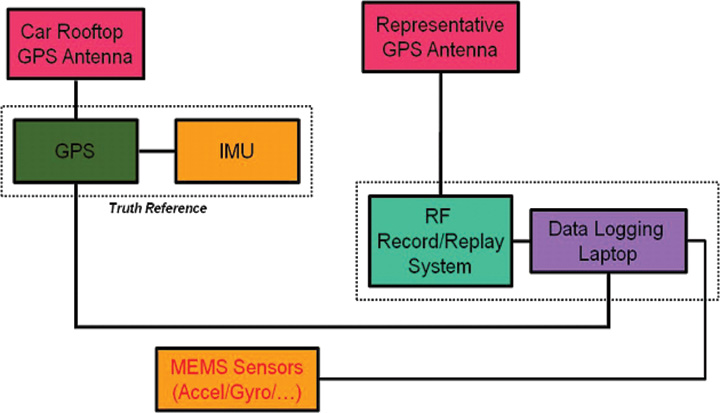
FIGURE 1. Traditional in-vehicle receiver testing.
Radio frequency record-and-playback systems (RPS) have recently become commercially available. These systems sample the RF environment and store it to disk during a drive test and can replay it through receivers back in the lab environment. Here we explore the improvements in dynamic testing methodology created by these units.
RPS test system installation.
RPS constitute a stark contrast to more traditional signal simulators that use pre-defined trajectories and mathematical models to determine appropriate RF output. Signal simulators attempt to reproduce environmental error factors such as multipath, inertial aiding system errors, and building and vehicle obstructions. They rely on mathematical models to simulate these various error sources. In some cases they do a reasonable job of reproducing these errors, but the dynamic urban environment is so complex (for example, rapidly varying/fading signal strength(s), multiple multipath signals, short/long duration obstructions of multiple layers) that even a sophisticated mathematical model can not replicate all effects completely. Some simulators include software that enables the user to define a trajectory and a limited amount of urban scenario details. Again, only so much realism can be created in a simulation environment. Existing testing standards are simulator-based, and as such, are circumscribed by the signal simulator limitations in representing a dynamic environment.
Positioning performance of a satellite navigation receiver under test (RUT) is coupled with its RF front-end system and local oscillator quality. Because of the variation in RF components between RUTs, some likely have superior RF interference (RFI) immunity. RFI can be a serious issue in certain land vehicles due to on-board electrical systems or because of external interference sources.
This article describes a testing method applicable to all receiver types, and complementary to that described in the December 2009 GPS World article by Mitelman and colleagues, “Testing Software Receivers,” regarding validation testing within a production environment. Added elements include taking into account truth-system uncertainty and a repeatability verification of the RF playback process through non-deterministic hardware receivers.
We present here the dynamic testing approach currently used at the University of Colorado in Boulder for receiver evaluation and comparison in the urban environment. The approach also includes the ability to assess the effect of sensor augmentations (for example, inertial, environmental) on positioning performance.
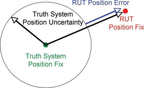
Truth Reference. Comparison with a truth reference system is essential for evaluation of satellite navigation receivers. For dynamic testing, this typically includes a survey-grade receiver coupled with a tactical-grade (or better) inertial measurement unit (IMU) and associated carrier-phase differential post-processing software. This software is filter-based and provides a positioning-error estimate in various components. Truth reference systems provide a continuous position estimate whose quality can vary depending on factors experienced in the urban environment, including length of full/partial satellite signal outage. In this study, we subtracted the 99th-percentile horizontal positioning error estimate of the truth system from the nominal RUT positioning error at each reporting epoch, as shown in Figure 2.
If the RUT position happens to lie within the truth-system position uncertainty, it is not considered to have any position error.
We focus here on a method to evaluate and compare mass-market, consumer-grade receivers to survey-grade receivers. One difference between these two receiver types is the way they handle the trade-off between accuracy and availability. Consumer receivers strive to provide the user with the highest availability, whereas survey receivers’ goal is to maximize accuracy. As a result, consumer-grade receivers will produce more regular position updates in harsh signal-tracking conditions, but must sacrifice accuracy to do so.
FIGURE 2. RUT position error calculation
Current Testing Standards
Currently accepted A-GPS standards such as those used by the 3rd Generation Partnership Project (3GPP) provide very limited dynamic testing in simulated urban conditions, being mainly designed to evaluate the first position calculation achieved in a particular simulated scenario. High-sensitivity receivers that pass or greatly exceed the 3GPP tests, in our opinion, are not guaranteed to have superior navigation performance in urban areas. Also, local oscillator performance is not specified. The trajectory dynamics imposed can actually be much smaller than the clock dynamics of a very low-cost local oscillator. A GPS receiver cannot tell the difference between the two and must track the effective Doppler variation.
The 3GPP defines five independent tests for A-GPS receiver certification. They include tests in the areas of: sensitivity with coarse/fine time assistance, nominal accuracy, dynamic range, multipath performance, and moving scenario/periodic update performance. The last three tests include elements that ostensibly pertain to the urban environment. These tests specify discrete, constant signal power levels for implementation in a hardware signal simulator. The discrepancy between the 3GPP-prescribed signal levels and those observed during actual drive testing is detailed as follows.
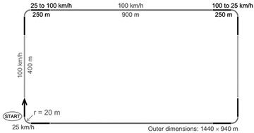
The 3GPP moving scenario/periodic update performance test trajectory is shown in Figure 3.
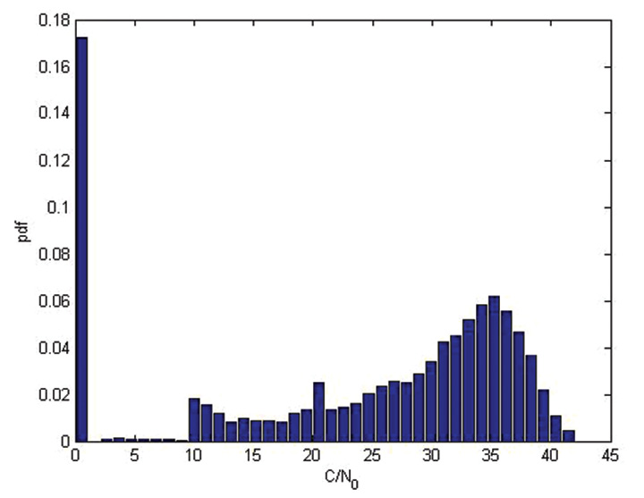
This test profile calls for the simulation of five satellites with a constant signal strength of 2130 dBm while the vehicle travels around the racetrack trajectory. In contrast, during an actual drive test in an urban area, a receiver reported the distribution of carrier-to-noise-density values for all tracked satellites as shown in Figure 4. This more accurately shows the range of signal strengths that should be expected in urban conditions.
FIGURE 4. Drive-test C/N0 distribution
The 3GPP moving test is considered passed if positions are reported regularly, and 95 percent of them are within 100 meters of the true position. This is not a particularly difficult test for a RUT to retain signal lock through, as the linear acceleration is about 0.15 g and the centripetal acceleration is about 0.25 g.
It is difficult for independent third parties to carry out a receiver evaluation following 3GPP guidelines as several of the tests require receiver restarts, which in turn requires testing automation. Depending on the receiver-evaluation hardware availability, restart commands may not be available to to an independent evaluator.
3GPP receiver testing results are quoted as pass or fail over a large number of short evaluations. For the dynamic environment, the system performance over continuous time is required to make a proper comparison between evaluated receivers.
In general, evaluating the GPS engines embedded within cell phones or other devices is difficult. Most are not made to interface with an external antenna, and the mere act of adding an antenna connection can significantly alter performance. The output format is not always documented, if it is even available to an end user. To allow fair across-the-board comparisons, GPS chipset manufacturers should make available development kits that have external antenna connections and well-documented message output formats.
Drive-Test Configuration
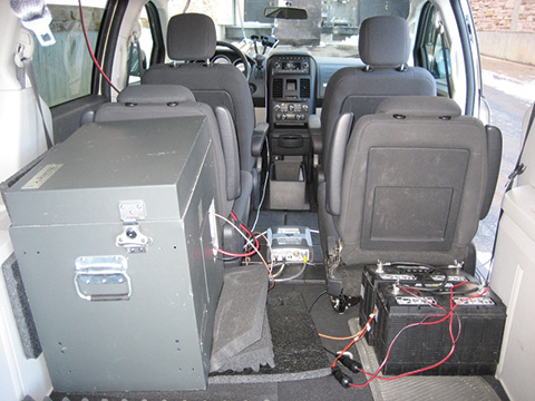
Current live dynamic testing requires multiple systems to be operating in a moving vehicle (see opening Figure 1). A truth-reference system, usually a high-grade GPS/INS device along with post-processing, provides the basis to which all other RUT are compared. This system requires a dedicated vehicle rooftop antenna with the best possible sky view, separate from a lower-grade test antenna located within the vehicle. Each RUT is connected to the representative consumer-grade antenna located in the vehicle through a high-isolation splitter that suppresses inter-receiver interference. It is important at this point that the gain be set appropriately for each RUT, depending on the front-end expectations while maintaining an equivalent noise figure across all receivers.
Visualization Methods
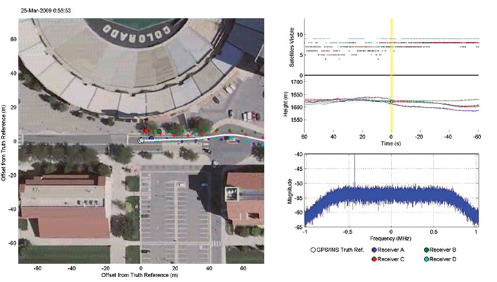
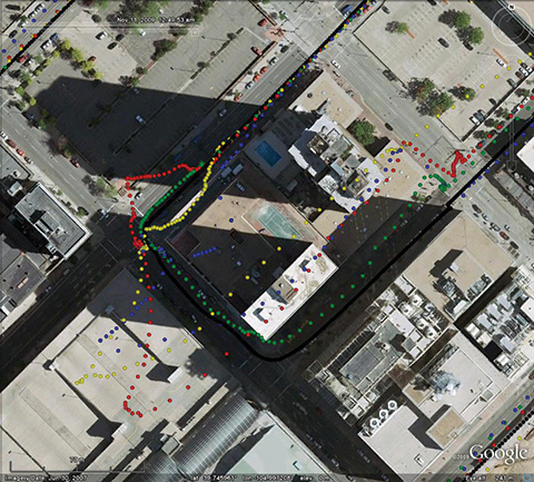
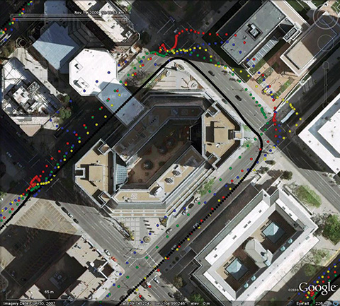
In addition to quantitative methods, we have created a qualitative visualization to assist with interpretation of the raw data. The same parsed data sets that provide the statistical script input are fed into a viewer script along with the post-processed truth reference data. With the truth-reference system data plotted in the center of the screen, each RUT is then plotted the correct distance and direction away, based on the distance and direction of error compared to truth. The receiver plots are overlaid onto Google Earth images centered on the truth-reference location. Plots of number of satellites utilized (top right of Figure 5) and elevation (middle right) as reported by each receiver and the sampled RF spectrum (lower right) are also included.
For each reporting epoch, based on the data frequency of the truth-reference system, a frame is generated with the aforementioned characteristics. These frames are gathered and encoded into a movie clip which can then be used as a quick and simple qualitative tool for receiver comparison. Figure 5 shows an individual movie frame. A forward-looking camera capability is also being added to this movie so the test environment can be documented from multiple angles.
FIGURE 5. Movie visualization screenshot
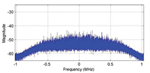
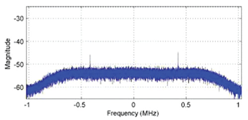
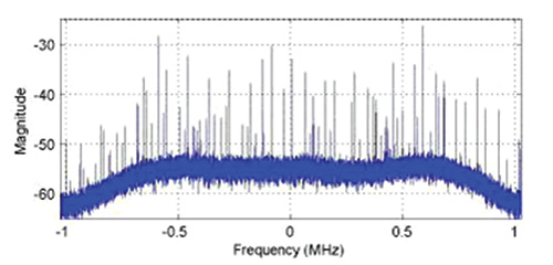
While observing this movie, variations in the sampled RF spectrum from interference or blockages can be associated with the current landscape. Locations of RFI sources can be identified and avoided (or included) in future testing. These RFI and significant blockage locations are of interest for receiver RF component and navigation filter development. The next three figures show spectrum snapshots during various parts of a drive test. In Figure 6, the cumulative GPS spectra rises above the noise floor and is visible during open sky conditions. While below ground level, Figure 7 shows only the front-end filter shape (and relatively minor RFI). Figure 8 shows an example of severe RFI when near a specific parking garage location.
FIGURE 6. Open-sky spectrum (centered on 1575.42 MHz)
FIGURE 7. Spectrum while below ground level (centered on 1575.42 MHz).
FIGURE 8. Spectrum near interference source (centered on 1575.42 MHz).
Record/Playback Concept
To overcome the limitations of hardware signal simulators and repeated vehicle drive testing, the RF record/playback testing method is utilized at the university. Commercially available equipment, capable of recording and playing back an RF signal, has recently become available. Equipment options exist for between $10,000–100,000, with 1–16 bit sampling and 4–25 MHz front-end bandwidth.
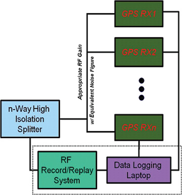
Figures 9 and 10 show the concept of “record once, playback many times.” During a drive test, the truth-reference system and RF recording system log samples to disk. There is no need for the RUT to be included during the actual drive test.
In the laboratory, the logged RF samples are replayed through a splitter to all RUT. The effect of receiver configuration changes can be evaluated without having to repeat the drive test. At a later time, additional receivers can also be tested using the same stored RF sample file.
During separate record and playback phases, testing considerations and methods discussed previously are implemented.
Since the recording process can only obviously capture current conditions, additional drive-test collections are required if different satellite geometry is desired, or if additional representative antennas need to be evaluated.
Repeatability of RPS Testing
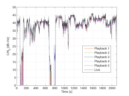
To validate that the playback signal levels were not significantly different from live signals, we conducted an urban, dynamic evaluation. Figure 11 shows that there is typically not more than a 1 dB difference in reported C/N0 between live and playback modes when testing a receiver that only reported integer values. The two dropout instances were excursions into parking garages.
FIGURE 11. Live and playback C/N0 values
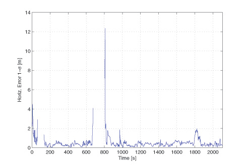
Figure 12 compares the navigation statistics between replays, using the same five playbacks as in Figure 11. The playbacks show a 1-sigma horizontal position solution spread under 1 meter for approximately 83 percent of the test.
FIGURE 12. Playback Horizontal Position Error Spread.
These two figures verify the repeatability of the RPS testing method and solidify it as an alternative to both signal-simulator testing and live testing of satellite navigation receivers.
Denver Testing Method
To evaluate the RPS concept, we conducted tests in three locations: Boulder, Denver, and Interstate Highway 70, all in Colorado. The Boulder and Denver locations were urban collections, while the Interstate 70 location was a natural canyon with significant elevation change. The collection at each location was repeated with two different representative antennas (patch and cell phone) at nearly the same sidereal time in order to keep the overhead satellite constellation similar.
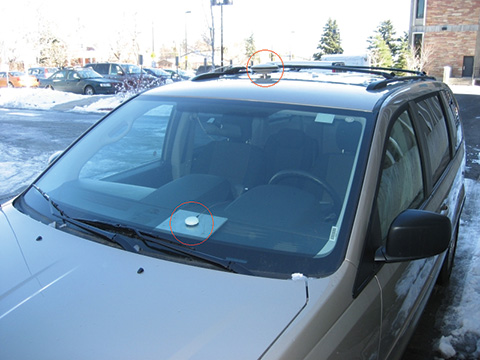
We examine here the November 11 and 16 Denver tests. The November 11 test used a patch antenna that places nearly all its gain in the upward direction, making it more immune to interfering sources below and to its sides. Figure 13 shows the patch antenn
a location on the van, as well as the truth-system antenna location utilized for testing on both days.
FIGURE 13. Patch antenna (dashboard) and truth-system antenna (rooftop) locations.
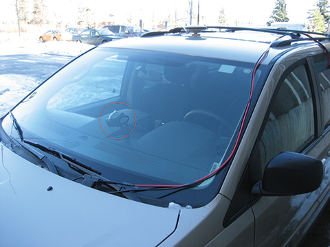
The November 16 test used a cell-phone GPS antenna that does not have a preferential gain direction, making it more susceptible to interfering sources below and to its sides. This antenna type is representative of the typical low-cost antenna (in some cases as simple as a piece of wire) found in consumer cell phones. Figure 14 shows the cell-phone antenna suction-cup mounted to the front window of the testing van. The representative antenna mounting location was chosen to minimize locally-generated RFI effects while also being representative of a typical vehicle-use case.
FIGURE 14. Cell-phone antenna location.
The required equipment and connections are minimal when performing RPS drive testing, as no RUTs are included. The inset to Figure 1 at the beginning of this article shows the RPS unit in the rear of the van, mounted on layers of foam to reduce vibration, which, if not properly addressed, can cause errors in mechanical hard drives writing data at high rates. Also visible are the truth receiver on the center of the van floor, and the car batteries for powering it and the IMU. The IMU is mounted to the vehicle frame and is not shown.
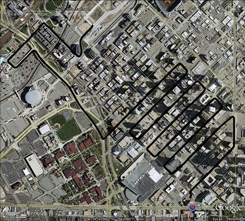
The test drive trajectory through Denver on November 11 and 16 as reported by the truth system is shown in black in Figure 15 and is also repeated in Figures 16 and 17. The test lasted approximately 40 minutes on both days. It started in the upper left part of Figure 15 and continued zig-zagging through downtown to the lower right.
FIGURE 15. Truth trajectory for November 11 and 16 tests.
Figures 16 and 17 show particularly difficult blocks for the four receivers tested under the replay method. These receivers are denoted A (green), B (blue), C (red), and D (yellow).
FIGURE 16. Difficult block #1 during November 11 test and truth system antenna (rooftop) locations.
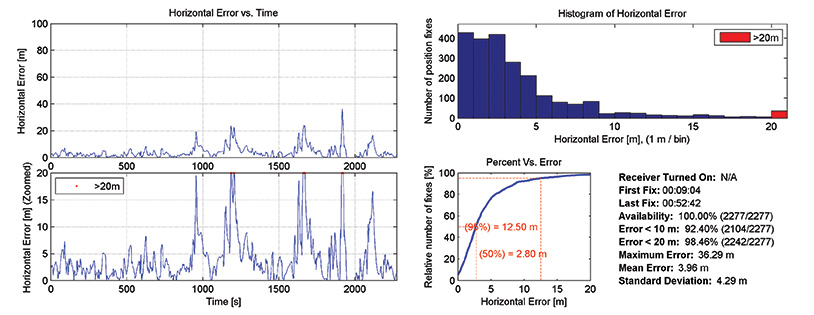
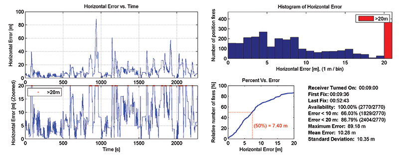
The horizontal positioning error statistics for two receivers on the November 11 test are shown in Figures 18 and 19. The left side shows horizontal error in two different zoom levels. The right side shows a histogram and cumulative distribution of errors, and several reporting metrics over the entire test. Even though receiver A in general outperformed receiver B, from the error time histories there are noticeable periods where both receivers simultaneously had positioning difficulties.
FIGURE 17. Difficult block #2 during November 11 test.
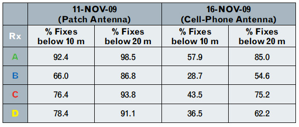
Table 1 summarizes the horizontal positioning statistics for all receivers during both tests. Positioning accuracy was severely degraded when replaying samples collected with the cell-phone antenna as compared to the patch antenna. Receiver A was the most accurate across both tests, while receiver B was the least accurate. The uncertainty of the truth system was subtracted out when producing the horizontal positioning results for all receivers.
Table 1
Conclusions
The record-and-playback system testing approach, in our opinion, represents the best way to test hardware receivers. It overcomes the fidelity limits of simulator-based testing, especially when considering the difficult-to-model urban environment. During receiver development, it requires only a single drive test for each location, as sampled RF data can be replayed from disk.
Having demonstrated that RPS testing is repeatable, we have produced a library of RF sample files representing real-world conditions for continued receiver development and testing purposes.
Eric Vinande is Ph.D. student at the University of Colorado studying GPS/MEMS inertial sensor integration and urban RFI aspects.
Brian Weinstein is a BSEE student participating in the Undergraduate Research Opportunity Program for GNSS receiver testing at the University of Colorado.
Tianxing Chu is a visiting researcher at the University of Colorado from Peking University where he is a Ph.D. student.
Dennis Akos is an associate professor within the Aerospace Engineering Sciences Department at the University of Colorado with concurrent appointments at Stanford University and Luleå University of Technology.
Manufacturers
Development of the methodology described here used two different RPS systems, one from LabSat (RaceLogic) and one from Averna. The test data come from the Averna system.
The U.S. International Trade Commission (ITC) has said it will review the determination of one of its administrative law judges that previously found that SiRF Technology infringed on patents held by Broadcom subsidiary Global Locate.
The ITC judge ruled in August that certain SiRF products, including SiRFstarIII and SiRFInstant GPS architectures, infringed upon six Global Locate/Broadcom patents; the judge later recommended to the ITC that it issue a ban on the import of related SiRF chips into the United States.
Both SiRF and ITC staff filed appeals independently of one another seeking a review of the ruling. Now, the ITC has said it will review claims on three out of the six patents, according to SiRF.
The commission has requested written submissions from the parties involved to address the form of remedy, if any, that should be ordered. According to the notice, if the commission contemplates some form of remedy, it must consider the effects of that remedy upon public interest, SiRF noted.
The final ITC ruling, slated for December 2008, is further subject to a 60-day presidential review period and can then be appealed to the Federal Circuit Court of Appeals.
SiRF, Qualcomm Play Nice
Apparently SiRF and Qualcomm want to avoid the legal snafu in which SiRF and Broadcom are currently embroiled. SiRF also announced that it and Qualcomm have signed a mutual Patent Non-Assertion Agreement covering each party’s patent portfolio.
“We believe that this agreement between leading innovators of A-GPS enabled location technology will help expand the market for location-enabled products, services and content, while enabling each of us to compete in the marketplace based on product merits,” said Kanwar Chadha, SiRFs founder and vice president of marketing.
It’s been a busy week for SiRF; on Wednesday it took the wraps off its SiRFlinkIII, a single chip that combines a GPS RF front end with a Bluetooth 2.1 + EDR controller.
The U.S. International Trade Commission (ITC) has denied the request of SiRF Technology to review its initial determination that found that Broadcom subsidiary Global Locate Inc. didn’t infringe two SiRF GPS patents.
ITC Administrative Law Judge Paul Luckern had previously ruled that two of SiRF’s GPS patents were not infringed by Global Locate and that the asserted claims of one of the patents were invalid, following a six-day trial last March, according to Broadcom. SiRF had already dismissed two additional patents from the case before trial.
This ITC case is separate from a case in which an ITC judge ruled earlier this month that certain SiRF Technology products, including SiRFstarIII chipsets, infringe six patents related to improving GPS processing and sensitivity held by Global Locate.
Broadcom and SiRF have been battling on multiple fronts over patent infringement claims in federal court, the ITC, and before the U.S. Patent and Trademark Office. The August 8 ITC ruling against SiRF caused the company’s stock to take a pounding on Wall Street.
A U.S. International Trade Commission (ITC) judge has ruled that certain SiRF Technology products infringe six patents related to improving GPS processing and sensitivity that are held by Global Locate Inc., a wholly owned subsidiary of Broadcom.
The infringement findings cover a range of SiRF products, including those incorporating the SiRFstarIII and SiRFInstant GPS architectures, according to Broadcom.
The ruling came Friday, August 8, just a day after SiRF said it had asked the U.S. Patent and Trademark Office reexamine four patents that are the subject of an infringement suit Broadcom has brought against SiRF in federal court. Furthermore, In June the ITC rejected claims by SiRF Technology that Global Locate infringed upon two of its patents, and also found that SiRF’s asserted claims on one of the patents at issue were invalid.
The ruling Friday followed a trial earlier this year. Broadcom said it expects a final determination by the full six-person commission by early December.
The six patents that SiRF was found to infringe are U.S. patents 6,417,801; 6,937,187; 6,606,346; 7,158,080; 6,704,651; 6,651,000 — relating to extended ephemeris assistance, calculating time in GPS receivers, enhancing sensitivity in assisted GPS systems, and implementing hardware structures for parallel correlation, according to Broadcom.
SiRF Technology Holdings, Inc. of San Jose, California, has completed filing with the U.S. Patent and Trademark Office official requests for reexamination of each of the four patents that Broadcom recently asserted against SiRF in the Santa Ana, California, federal district court.
SiRF seeks review and invalidation of all four of the Broadcom patents named in the lawsuit, through its requests for ex-parte reexamination and in view of what it terms “substantial new questions of patentability raised by prior art not previously considered by the Patent Office,” according to the company.
SiRF also intends to seek a stay of the federal district court case.
SiRF and Broadcom have been engaged in an ongoing legal battle over patents held by their respective companies, both claiming patent infringement. In late June, SiRF Technology petitioned the International Trade Commission (ITC) to review part of a ruling that found that Broadcom didn’t infringe upon two of its patents as the company alleged.
A ruling in Broadcom’s six claims of patent infringement against SiRF before the ITC is expected any day. The trial took place in April.
SiRF Technology has petitioned the International Trade Commission (ITC) to review part of a ruling earlier this month that found that Broadcom didn’t infringe upon two of its patents as the company alleged.
ITC Administrative Law Judge Paul Luckern issued his initial determination in the suit originally filed by SiRF against Global Locate on June 13 following a six-day trial in March in Washington, D.C. Broadcom acquired Global Locate in July 2007. The judge subsequently found that Broadcom didn’t infringe on SiRF’s intellectual property, and found one of the two patents in question to be invalid.
SiRF said it has petitioned the ITC to review those aspects of the initial determination that found that the valid patent was not infringed by Broadcom.
The intellectual property dispute goes back to 2006, when SiRF also took Global Locate to task in federal district court; it in turn counter-sued. Those suits were stayed pending the ITC ruling.
Broadcom also has its own claims against SiRF before the ITC, having filed six claims of patent infringement; that trial took place in April of 2008. An initial determination in that case, heard before Administrative Law Judge Carl Charneski, should come on Aug. 8, 2008, according to the company. Broadcom also filed a lawsuit in May 2008 in federal district court, claiming infringement of four patents.
Broadcom Corp. says the U.S. International Trade Commission (ITC) rejected claims by GPS chip maker SiRF Technology, which alleged that Global Locate infringed upon two of its patents. Furthermore, the ITC also found that SiRF’s asserted claims on one of the patents at issue were invalid, according to Broadcom.
Broadcom acquired Global Locate in July 2007; the patent dispute stems back at least to 2006, when SiRF also took Global Locate to task in federal district court; it in turn counter-sued. Those suits were stayed pending the ITC ruling. ITC Administrative Law Judge Paul Luckern issued his initial determination Friday, June 13, following a six-day trial last March in Washington, D.C.
Broadcom also has its own claims against SiRF before the ITC, having filed six claims of patent infringement; that trial took place in April of 2008. An initial determination in that case, heard before Administrative Law Judge Carl Charneski, should come on August 8, 2008, according to the company.
Broadcom also filed a lawsuit in May 2008 in federal district court, claiming infringement of four patents.
While European regulatory authorities are closely scrutinizing the proposed TomTom/Tele Atlas merger, they have also turned their eyes to the proposed Navteq/Nokia deal.
Navteq Corp. said today that the European Commission has initiated a second-phase review of Nokia’s pending acquisition of Navteq. The company stressed in its announcement that this is part of the commission’s review process and does not signal the ultimate outcome. Nevertheless, it is a rare, if not extraordinary step for the commission; in the past 10 years it has only initiated a second-phase review in about 3 percent of European mergers of publicly held companies.
The Commission now has 90 working days to make a final decision on the transaction. However, the review period may be extended to 125 working days. Such has been the case with the TomTom/Tele Atlas deal, also under a second-phase review. Those two companies are anticipating a commission decision on their merger by May 21.
Both Navteq and Nokia said they remain committed to their merger plans, noting that the deal has received all the other necessary regulatory approvals, including anti-trust approval in the United States.
Meanwhile, TomTom said March 27 that it was extending the period of its offer for Tele Atlas. It was clear the European Commission wouldn’t reach a decision by the end of the previous time frame attached to the offer to acquire Tele Atlas for €30 per share, or about €2.9 billion, which would have ended March 31, TomTom said. As result, it has extended its offer to May 30. The Commission originally announced that it was initiating a second-phase review of the merger in November of last year.
Navteq Corp. said Wednesday that its stockholders have approved the company’s pending merger deal with Finnish mobile phone giant Nokia.
Shareholders representing more than 75 percent of the issued and outstanding shares of common stock eligible to vote and nearly 100 percent of the total votes cast at the special meeting Wednesday, voted in favor of the merger agreement. That move follows the company’s announcement late last week that it had received early termination of the mandatory waiting period under the U.S. Hart-Scott-Rodino Antitrust Improvements Act.
Upon satisfaction of the remaining closing conditions, under the terms of the merger deal each outstanding share of the common stock of Navteq will be converted into the right to receive $78 in cash, without interest, and Navteq will survive the merger as a wholly-owned subsidiary of Nokia Inc., according to the company. All unvested options to purchase common stock will accelerate and vest in full immediately prior to the consummation of the merger. Option holders will receive a cash payment for each option held equal to the excess of $78 over the applicable option exercise price, less taxes.
The European Commission (EC) is taking a closer look at TomTom’s planned acquisition of TeleAtlas; it looks as if it might have a tough European road to hoe. The EC only initiates a second review in about 3 percent of the mergers it reviews, so it’s a bit of an extraordinary step. The probe will examine whether the deal would push up the price of digital maps for rival portable navigation device makers or limit their access to these maps, the EC said. It set an April 17 deadline for the probe to end.
TomTom and Tele Atlas said in a joint statement they expect to have a clearer idea about whether the deal can go through by early next year. TomTom extended its offer for Tele Atlas shares until March 31, assuming it would know the outcome of the probe by then.
Navteq Corp. said Monday that it has scheduled a special meeting of stockholders next month to consider approval of the previously announced merger agreement between the company and Nokia.
Finnish mobile phone maker Nokia and digital map supplier Navteq first announced on October 1 that they had reached a definitive merger agreement to the tune of $8.1 billion (€5.7 billion). In the meantime, PND rivals Garmin and TomTom became involved in a bidding war over Tele Atlas, a Navteq competitor.
Navteq stockholders of record at the close of business on November 13, 2007, are entitled to notice of the special meeting and to vote on the adoption of the merger agreement, according to the company. The special meeting will be held on December 12 in Chicago. Proxy statements and the accompanying proxy card were mailed to Navteq stockholders earlier this month, the company said.
Completion of the merger is subject to the adoption of the merger agreement by Navteq stockholders at the special meeting and the satisfaction of the other closing conditions set forth in the merger agreement. Navteq currently expects to complete the proposed merger in Q1 of next year.