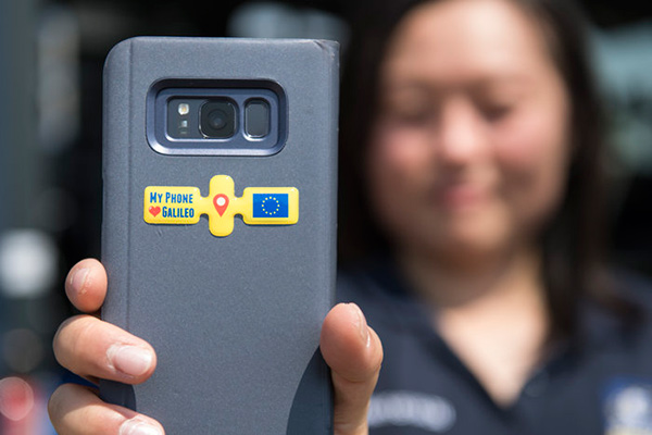
Testing of the three Galileo apps took place in May. (Photo: ESA)
ESA challenged its young graduate and national trainees to develop a smartphone app to perform satnav fixes using only Galileo satellites.
Three teams developed apps in their spare time, presenting their results to a jury of experts from ESA, the European Global Navigation Satellite Systems Agency (GSA) and Google.
“I’m very impressed,” said Javier Benedicto, ESA’s Galileo programme manager. “With little detailed knowledge of satellite navigation, these teams have developed something that didn’t exist just a few months ago. Working on Galileo we love to see that the systems we’re putting together can reach widespread application and inspire new uses.”
The winning Galfins Team put together the GNSS Compare app that promises to turn a smartphone into a “research lab in your pocket” to test Galileo performance in isolation or in combination with other systems. Their prize is to attend an ESA and European Commission-sponsored GNSS Summer School in Austria.
The final presentation and results of ESA’s internal Galileo smartphone app competition took place in the Erasmus centre of ESA’s Erasmus technical centre on May 31. (Photo: ESA)
“Only one of our four-strong team started the challenge with any knowledge about satellite navigation,” said Mateusz Kraiński of the Galfins team. “The rest of us come from different areas — for example, I’m working on the European Robotic Arm project, due to launch at the end of next year. We have learnt a lot and the radio navigation experts at ESTEC were a great source of support.”
“We see a need on the market for such an application, so we will definitely continue with the development. The application will be made available for download when ready, and the project will be released as open source soon after.”
The other two teams were also commended for their work; Chocolateam developed a richly-designed game-based app, giving the user the feeling of observing the Galileo satellites from a spacecraft, while Team 5G distinguished themselves by writing all their own navigation algorithms from scratch rather than relying on open source software.
The challenge was to design an Android smartphone app that allows users to compute and visualize their position based solely on Galileo measurements, as well as the possibility of selecting a combination of satnav constellations to assess their performance.
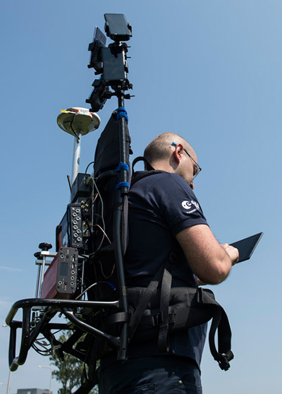
Testing the three apps entered in the Galileo smartphone app competition in the grounds of ESTEC, working in pedestrian mode. (Photo: ESA)
The receiver chipsets inside smartphones make use of Galileo signals in combination with several other satnav constellations — the U.S. GPS, Russian GLONASS and Chinese BeiDou. These chipsets function like “black boxes,” making the resulting positioning fix accessible to users, but not giving any option for the user to select which constellation to employ.
Current phone applications only display general satnav status information, such as which satellites are contributing to the positioning fix, their visibility parameters and overall power levels. This is not sufficient to single out Galileo’s contribution to the phone’s overall positioning performance.
However, in newer Android smartphones it has become possible to access the raw signal measurements used to compute position, opening the door to the development of applications where the user can indeed select which satellites to use.
The teams received one Galileo-enabled smartphone each for developing and testing the app.
ESA’s Director of Technology, Engineering and Quality supported the teams by supplying dedicated software modules to simplify computations of the phone position. During the competition, a technical advisory team also developed an internal app as a benchmark.
The app, named Galileo PVT and developed by ESTEC engineers Paolo Crosta and Tim Watterton, includes an augmented reality system allowing users to “see” the Galileo satellites from which they were receiving signals in the local sky.
“This was a very useful exercise because it helps us understand the needs of satnav app developers in Android,” said the lead advisor, Paolo Crosta. “Then, once the apps were complete, we tested them together, here on the grounds of ESTEC, working in stationary, pedestrian and vehicular modes.”
“Congratulations to all the teams here today,” said Frank Van Diggelen from Google, who had just come from a satnav raw measurements workshop hosted by GSA. “It’s been great to be here and see all the activity around raw signal measurements. Our aim has always been to raise standards by making these measurements available, to let developers see what’s happening inside. And the work you’re doing here is feeding back to chip and smartphone manufacturers, to help change and improve them for the future.”
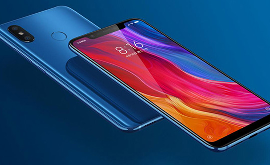
Mobile brand Xiaomi has launched a dual-frequency GNSS smartphone.
Fitted with a Broadcom BCM47755 chip, the Xiaomi Mi 8 provides up to decimeter-level accuracy for location-based services and vehicle navigation, the company said.
The Mi 8 smartphone represents a breakthrough in GNSS technology as the first commercial deployment of Broadcom’s dual-frequency BCM47755 chip designed for the mass market and introduced in September 2017.
Until now, mobile location-based applications have been powered by single-frequency GNSS receivers whose location accuracy is limited to a few meters. However, in recent years GNSS systems have been launching satellites broadcasting signals on new frequencies to open up new possibilities. Specifically, Galileo has the majority of satellites with E1/L1 and E5/L5 frequency capabilities.
The E1/L1 + E5/L5 GNSS chip can compute location with an accuracy of up to a few decimeters.
Leveraging Galileo for increased accuracy
According to the company, users of the Xiaomi Mi 8 and future models with dual-frequency GNSS will benefit from better positioning and navigation experience in urban environments. This is due to the unique shape of the E5/L5 frequency, which makes it easier to distinguish real signals from the ones reflected by buildings, reducing the multipath effect, a major source of navigation error in cities and other challenging environments.
The numerous Galileo satellites broadcasting E5 make this improvement available for users all around the world. In addition, the simultaneous use of two frequencies reduces other sources of error, such as those due to the ionosphere, and the frequency diversity is more robust to interference and jamming.
In addition to making existing applications more accurate, the enhanced position precision offered by dual-frequency GNSS will also create opportunities for new applications in areas such as augmented reality, vehicle navigation and mapping.
Commenting on the product launch, European GNSS Agency (GSA) head of market development Gian Gherardo Calini said that the arrival of the first dual-frequency GNSS smartphone to the mass-market represents a breakthrough for users all over the world.
“The enhanced accuracy provided will empower developers to create new applications that meet the growing high-accuracy location requirements of users and also open up applications that previously only ran in dedicated devices intended for professional use,” Calini said.
“Broadcom is glad to gear up Xiaomi’s flagship smartphones with the very latest dual-frequency GNSS technology,” added Alex Chou, vice president of product marketing for the Wireless Communications and Connectivity Division at Broadcom. “Xiaomi Mi 8, the world’s first smartphone with BCM47755, will take smartphone GNSS navigation to a whole new performance level.”
”The importance of GNSS to modern life is undisputed, and is particularly important for smartphones,” said Zhiyuan Zang, Xiaomi’s director of product marketing. “Navigation and LBS-based apps these days require greater positioning accuracy to work effectively, and dual-frequency GNSS is the key to delivering a great user experience when using these apps. Xiaomi is delighted and honored to be the world’s first smartphone manufacturer to support dual-frequency GNSS. We will continue to pursue innovation for everyone to enjoy.”
Access to raw measurements for geolocation
The launch of the first dual-frequency GNSS smartphone, together with the opportunities offered by the availability of GNSS raw measurements in Android, creates exciting opportunities for the geolocation community, the company said.
Access to raw measurements opens the door to algorithms once restricted to more advanced GNSS receivers. This, in turn, allows users to fully benefit from the differentiators offered by Galileo.
Recognizing these opportunities, in 2017 the GSA engaged with academia and industry in the areas of navigation and positioning to innovate around this new feature as part of a GNSS Raw Measurements Task Force.
Then, in January, the GSA published a white paper on the use of GNSS Raw Measurements in Android, providing developers with in-depth information on accessing and using raw measurements to implement advanced GNSS techniques in mass-market devices.
Building on this work, the GSA and the Raw Measurements Taskforce shared their latest updates at a dedicated workshop — “GNSS Raw Measurements: From Research to Commercial Use” — held at the GSA headquarters in Prague on May 30, where Broadcom presented its encouraging test results from the dual-frequency BCM47755.
Location, principally provided by GPS/GNSS, plays a key role alongside deployment of 5G cellular networks, in the realization of the internet of things (IoT).
A free webinar hosted by GPS World on May 17 will cover how location plays a role in the internet of things. The webinar will include presentations by Fergus Noble, co-founder and CTO of Swift Navigation; Oliver Cameron, co-founder and CEO of Voyage; and Steve Thompson, senior director and office of the CTO of Acorn Technologies.
During his presentation, Noble will highlight the benefits of integrating a cloud corrections service with high-precision GNSS receivers. He also will provide an understanding for users of GPS about how high-precision GNSS receivers benefit from a cloud corrections service, including high-precision results in seconds and increased geographic range.
Cameron will cover why private cities make for the perfect first deployments of self-driving cars and Thompson will offer an overview on cellular positioning technology for ultra-low-cost, ultra-long-battery-life IoT applications.
Qianxun Spatial Intelligence Inc., a high-precision positioning service provider, and u-blox are joining forces to deliver high-precision positioning solutions to the Chinese market.
By coordinating their product offerings, they seek to meet growing demand for increased positioning accuracy for mass-market applications. Some of the areas driving up demand for high-precision positioning services in China are internet of things (IoT) tracking devices such as those used on shared bikes, as well as automotive, UAV and robotic vehicle applications.
u‑blox is bringing to the partnership its high-precision GNSS receivers. Its u‑blox F9 multi-band positioning platform uses integrated real-time kinematic (RTK) technology to process the high-precision positioning correction data provided by Qianxun SI, delivering down to centimeter-level positioning accuracy for wide-ranging applications. It enables even faster and more robust performance by leveraging a greater variety of GNSS signals.
Two major advancements have enabled sub-meter-level positioning accuracy for mass-market applications. The first is modern GNSS correction services that constantly monitor GNSS signals to determine positioning errors caused, for example, by atmospheric distortions, and wirelessly transmit correction data to compensate for these errors to millions of GNSS devices. The second is a new generation of small, power-efficient, and affordable GNSS receivers that are able to use the correction data to achieve such high levels of accuracy.
Qianxun SI, a high-precision positioning service provider, has already laid the groundwork for the large-scale expansion of high-precision positioning in the IoT era, the company said. Based on BeiDou, which is compatible with GPS, GLONASS and Galileo, Qianxun SI’s high-precision positioning service is built on the nationwide ONE Network, composed of more than 2,000 Continuously Operating Reference Stations (CORS) and using proprietary algorithms. It offers vehicles and other applications a range of 24/7 high-precision positioning services in most regions of the country.
By the end of 2018, Qianxun SI’s dynamic centimeter-level service will cover the entire mainland of China, the company said.
“We are delighted to cooperate with u-blox to provide users with high-precision positioning solutions that are user friendly and affordable,” said Jinpei Chen, CEO of Qianxun SI. “I believe our high-precision positioning technology is a key enabler of IoT development, and the cooperation with u‑blox will accelerate the go-to-market process of the technology in an extensive range of industrial and automotive market applications.”.
“This collaboration is a genuine win-win for all involved in that it allows us to develop high-precision solutions that will foster innovation across markets,” said Thomas Seiler, CEO of u-blox. “Partnering with China’s leading GNSS correction service provider allows u-blox customers to bring cutting edge applications to the China market in the shortest possible time.”
The technological underpinning for stock markets’ techno-darlings doesn’t always work perfectly. That problem produces lost revenue and lost value. So Uber, for one, has done something about it, partly based on research developed by Paul Groves at University College London and featured in the February 2012 cover story of GPS World.
Smartphones finding each other in the urban landscape constitute Uber’s business basis. When driver and rider can’t find each other, because they’re on opposite sides of the street or even opposite sides of the block, a ride can’t happen. In the GPS world, we call this multipath, reflected signals, shadowing or simply urban canyon. In Uber parlance it is “wasted supply.”
To eradicate it, Uber acquired Shadow Maps in 2016 and has integrated the company’s technology into the Uber app. Beta testing now goes on in 15 cities; early results indicate that positioning accuracy has improved twofold.
The Shadow Maps process, derived from Groves’ shadow-matching concept, directs the Uber algorithm to examine a 3D rendering of the cityscape and perform a probabilistic estimate of user location based on — simultaneously — which satellites are in direct line-of-sight and which aren’t, in conjunction with predicted satellite location, or almanac.
The process uses ray tracing, color-coding satellite signals by strength to predict likely locations. Each probability calculation takes 20–100 milliseconds, and can run every four seconds for riders and more frequently for drivers, according to Uber engineers and former Shadow Maps principals Andrew Irish and Danny Iland.
“You just want to have a better, tighter estimate to account for how much faster cars move,” Irish said.
Prior Work. Paul Groves has researched this area for nearly a decade at the Space Geodesy and Navigation Laboratory, University College London, where he is an associate professor. Lei Wang won ION’s Parkinson Award for his Ph.D. thesis on shadow matching and now works at Apple. Marek Ziebart is a professor and vice-dean, research, UCL.
“There are many different approaches to 3D-mapping-aided GNSS and several different research groups around the world working on them,” said Groves. “At UCL, we have been integrating shadow matching with 3D-mapping-aided GNSS ranging algorithms. We now have a real-time demo system running on an Android smartphone, albeit limited to Central London. By making full use of the new Android ‘raw measurements’ capability, we get around a factor of 5 accuracy improvement over conventional single-epoch GNSS in dense urban areas.”
“It’s great to see people actually making use of our research rather than it just languishing in research papers. The more widely that shadow matching and other 3D-mapping-aided GNSS techniques are used, the better.”
In February 2012, Groves and his co-authors presciently wrote:
“A practical shadow-matching algorithm must be implementable in real time on a mobile device. Three models may be considered.
A network-based solution, whereby GNSS measurements are transmitted to a server, which stores the building boundary data, computes a solution and then sends it to the user.
A handset-based solution, where the shadow-matching algorithm is run on the handset, which also stores the building boundary data.
A hybrid model, whereby the shadow-matching algorithm runs on the handset, but the building boundary data is streamed from a server as and when required.
“Using stored or streamed building boundaries, fewer than 50 comparison and addition operations are required to calculate an overall shadow-matching score for one candidate position with two GNSS constellations. Therefore, shadow matching may be performed in real time on a mobile device with several hundred candidate positions, where necessary.”
The magazine article was based on a presentation at the European Navigation Conference 2011 in London. The authors will present their latest research, reflecting significant progress over the last seven years, at ION GNSS+ 2018 in Miami, Sept. 24-28.
Spirent Communications plc is working with the European Commission’s Joint Research Centre (JRC) to help implement the eCall system, which is required in new cars sold in Europe starting in April.
Experts from the JRC have been working with Spirent GNSS test equipment during the European GNSS Agency (GSA) eCall test campaign. The campaign aims to pre-test eCall in-vehicle modules and evaluate their compatibility with the positioning services provided by Galileo and the European Geostationary Navigation Overlay Service (EGNOS) in accordance with the test procedures established by the regulation.
As the eCall initiative goes live this month, the GSA launched a test initiative to support eCall device manufacturers in their preparation for type approval. In safety-critical situations, eCall must be as accurate as possible, so defining and conducting proper test procedures is imperative.
Spirent is cooperating with the JRC to develop its own eCall test solution. “Working with JRC enabled us to develop better tests to verify that eCall devices are working properly,” said Steve Hickling, product director for Spirent’s positioning business.
When a collision occurs, an eCall-equipped car automatically calls the nearest emergency centre. Even if no passenger is able to speak – such as because of injuries — a “minimum set of data” is sent, which includes the exact location of the crash site. eCall is expected to significantly reduce emergency service response times, leading to lives saved and injuries reduced.
The JRC used a Spirent GSS9000 simulator to assess eCall devices’s capability to support the reception and processing of the Galileo and EGNOS signals. Using feedback from the JRC, Spirent has developed an eCall Test Suite for its automation solution, PT TestBench.
Tested with various eCall devices, the eCall Test Suite is available for eCall device manufacturers and include, among others, positioning accuracy, time to first fix, GNSS receiver sensitivity and reacquisition performance.
Airgain Inc., a provider of advanced antenna technologies used to enable high-performance wireless networking, has released its Ultramax MIMO 9-in-1 antenna, which can receive multiple GNSS signals.
Designed for public safety fleet management, it provides high rejection GNSS technology with coverage for multiple satellite systems including GPS, GLONASS, Galileo and BeiDou.
The new Ultramax MIMO 9-in-1 antenna will help improve public safety and fleet solutions with enhanced Wi-Fi capability, the company said. It includes 6 x 6 MIMO Wi-Fi, dual LTE and multi-GNSS technology antennas in a single enclosure.
MIMO — multiple input multiple output — is used within LTE to provide better signal performance and higher data rates. With integrated 6×6 Wi-Fi antennas, the antenna provides support for full high-definition (HD) streaming video and other high bandwidth applications.
The antenna is the first in an Airgain series designed to support state-of-the-art communications technology in fleet routers, including the Cradlepoint IBR1700.
The Ultramax MIMO 9-in-1 antenna is equipped with nine ports, supporting tri-band Wi-Fi, LTE/MIMO (including Band 14 for FirstNet) and GNSS. With a single compact footprint, the antenna avoids multiple mounting and cable entry points.
“Technology advances in routers, including enhanced Wi-Fi and expanded MIMO LTE, require enabling antenna technology to deliver an optimized end user experience,” said Reed Pangborn, vice president of channel sales for North America. “We designed a new antenna to support the fleet management applications required in today’s evolving mobile environment. The Ultramax MIMO 9-in-1 antenna demonstrates our commitment to providing leading antenna solutions for our mobility customers covering a wide range of vehicles, including police, fire, ambulance and other fleet assets.”
The Ultramax MIMO 9-in-1 antenna complements Cradlepoint’s IBR1700 and supports all six of its Wi-Fi ports.
Airgain will unveil the new antenna at the Cradlepoint Global Partner Summit in Scottsdale, Arizona, April 11-12. The Ultramax MIMO 9-in-1 antenna will be available to order starting in June.
The U.S. Department of Homeland Security (DHS) has released a memorandum about a GPS rollover event coming in April 2019.
The memorandum, U.S. Owners and Operators Using GPS to Obtain Time, is intended to provide an understanding of the possible effects of the April 6, 2019, GPS Week Number Rollover on Coordinated Universal Time (UTC) derived from GPS devices.
DHS recommends that critical infrastructure and other owners and operators prepare for the rollover. They should:
investigate and understand their possible dependencies on GPS for obtaining UTC;
contact the GPS manufacturers of devices they use to obtain UTC;
understand the manufacturers’ preparedness for the ollover;
understand actions required by CI and other owners and operators to ensure proper operation through the ollover, and
ensure that the firmware of such devices is up to date.
The memorandum is sponsored by the Department of Homeland Security’s National Cybersecurity and Communications Integration Center in coordination with the Department of Homeland Security’s Science and Technology Directorate, the Department of Homeland Security’s National Protection and Programs Directorate Office of Infrastructure Protection and the National Coordination Office for Space-Based Positioning, Navigation and Timing.
GPS World discussed in-depth the previous rollover event in an Innovation column.
UWB is being used in a novel microwave imaging and localization system, one which features Antonio Vivaldi’s namesake antenna.
By Fengzhou Wang and Guohua Wang
INNOVATION INSIGHTS with Richard Langley
VIVALDI. No, you aren’t reading an article in Gramophone. This happens to be the name of a particular kind of broadband antenna, which is particularly useful at microwave frequencies and for ultra-wideband (UWB) applications in particular. It was invented by the British electrical engineer Peter J. Gibson in 1978 while working at Philips Research Laboratories. In a 1979 conference paper entitled “The Vivaldi Aerial,” Gibson described it as “a new member of the class of aperiodic continuously scaled antenna structures and, as such, it has theoretically unlimited instantaneous frequency bandwidth.” He went on to say “This aerial has significant gain and linear polarisation and can be made to conform to a constant gain vs. frequency performance. One such design has been made with approximately 10 dBI gain and -20 dB sidelobe level over an instantaneous frequency bandwidth extending from below 2 GHz to above 40 GHz.” Broadband indeed!
So why did Gibson name the innovative antenna “the Vivaldi aerial”? It has to do with its shape. Another term for the Vivaldi antenna (sometimes called the Vivaldi notch antenna) is the tapered slot antenna. The planar antenna, constructed out of thin metal sheet or printed circuit board (PCB), features a slot line gap cut out of the sheet or etched from the PCB, which gradually flares in the direction of wave propagation (see Figure 1 in this month’s article to see what a Vivaldi antenna actually looks like). Since the spacing of the gap is related to the wavelength of the radio waves that can be launched, the antenna can be used over a wide frequency range not unlike the log-periodic antenna used in shortwave broadcasting or the biconical antenna and its butterfly antenna subtype used for UHF TV reception. Of course, according to the reciprocity theorem, an antenna designed to transmit radio waves can generally be used to receive radio waves with the same antenna properties (gain, bandwidth and so on).
But let’s get back to the tapered slot antenna’s formal name. According to one his co-workers, the shape of the antenna reminded Gibson (who was also a musician and composer) of the cross-section of an early trumpet. So he named his antenna after Antonio Vivaldi, the famous baroque music composer, who wrote several concertos featuring trumpets. And 1978, the year of the antenna’s invention, was the three-hundredth anniversary of Vivaldi’s birth. It doesn’t hurt that the shape of the slot also looks a bit like a cursive “V” when the antenna is stood on its end.
While the basic Vivaldi antenna generates (or receives) linearly polarized waves, it is possible to combine two elements at right angles to generate (or receive) circularly polarized waves.
Because of its broadband characteristics and ease of PCB manufacturing, the Vivaldi antenna has been used extensively in UWB applications. Conventional radio transmissions use a variety of modulation techniques but most involve varying the amplitude, frequency and/or phase of a sinusoidal carrier wave. But in the late 1960s, it was shown that one could generate a signal as a sequence of very short pulses, which results in the signal energy being spread over a large part of the radio spectrum. Initially called pulse radio, the technique has become known as impulse radio ultra-wideband or just ultra-wideband for short. The bandwidths of UWB signals are quite large. For example, in the U.S., current Federal Communications Commission rules for pulse-based positioning or localization implementations require the applied bandwidth to be between 3.1 and 10.6 GHz and the bandwidth to be greater than 500 MHz or the fractional bandwidth to be more than 0.2.
The use of large transmission bandwidths offers a number of benefits, including accurate ranging and that application in particular is being actively developed for positioning and navigation in environments that are challenging to GNSS such as indoors and built-up areas.
In this month’s column, we learn how UWB is being used in a novel microwave imaging and localization system, one which features Antonio Vivaldi’s namesake antenna.
Indoor localization is challenging work using traditional location-based services such as GPS. Approaches for indoor position estimation have used radio-frequency (RF) signals including narrowband signals such as Wi-Fi and Bluetooth. Impulse radio ultra-wideband (UWB) signals have also been widely investigated. Compared with narrowband signals, UWB signals provide high signal-to-noise ratio, which helps to provide an accurate estimate of signal arrival time for time-based location algorithms such as time of arrival (TOA). Furthermore, UWB signals provide larger coverage areas and a ranging capability. Sub-millimeter positioning accuracy is achievable. And UWB-based location has an inherent high time resolution making it useful in a tracking system for medical and other applications.
A number of investigations in UWB positioning have already been carried out, with several relatively expensive commercial UWB kits available from companies such DecaWave and BeSpoon. But additional work still needs to be carried out to fully evaluate the UWB solution, so this is still an open research topic. One problem area requiring further investigation is positioning in the non-line-of-sight (NLOS) environment. This is considered the main challenge for UWB location, since it is associated with strong fading due to reflection and diffraction from various obstructions such as furniture in the room. Various threshold crossing methods using techniques of energy detection, correlation and the multiple signal classification (MUSIC) spectral analysis algorithm have been used to resolve the multipath propagation problem in NLOS environments. However, these approaches require complicated signal processing, which increases the computing cost.
Moreover, UWB technology is also being widely introduced in microwave imaging for military and biological applications. It provides high-precision detection and high-resolution images, depending, in part, on the operating frequency range. The radar-based microwave imaging or MWI is a time-domain confocal imaging method that aims to indicate the position of the targets by use of the delay time of the reflected signal. MWI technology highlights the target from the testing environment by using different values of the dielectric permittivity constant.
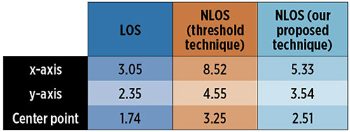
In this article, we propose a hybrid method combining MWI and localization of body-worn UWB antennas for improving the accuracy of indoor positioning. The proposed system will be able to differentiate an LOS environment from an NLOS environment using MWI detection ability, and then adjust the scanning antenna array setup using robotic support. Furthermore, we introduce a threshold value in the filter function to highlight major obstructions in an NLOS environment such as a physical item. Using this proposed system for TOA measurements, we have obtained an overall average accuracy in two-dimensional localization of around 1.7 to 2.5 centimeters.
SYSTEM EXPERIMENTAL SETUP
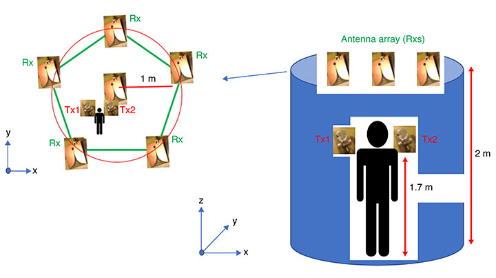
We have developed a robotic antenna array for indoor microwave imaging to assist in indoor location with wearable antennas. The basic architecture of the proposed UWB localization system consists of two components: tag antennas and anchor antennas. Two thin-film tag antennas are worn on both shoulders of a human, and seven wideband Vivaldi antennas (also known as tapered slot antennas), acting as anchor antennas, are mounted on individual robotic supports, which can adjust the height and the rotation angle of each antenna. All the antennas are fabricated with printed-circuit board (PCB) material to reduce the cost.
FIGURE 1. UWB antennas setup for the proposed location approach.
In FIGURE 1, the Vivaldi antennas are shown with blue dots and are placed on the top of the robotic support 2 meters above the ground. The antenna array covers a scanning area with a radius of 2 meters. The two compact wearable tag antennas are placed on the left and right shoulders of the target human at a nominal height of 1.7 meters.
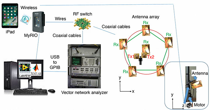
Other main components of the proposed system are shown in FIGURE 2.
FIGURE 2. The proposed system diagram.
The system can be manually controlled by an Apple iPad or automatically controlled by a personal computer (PC). The PC runs the National Instruments (NI) Laboratory Virtual Instrument Engineering Workbench (LabVIEW) programming environment and an NI instrument monitor for debugging the operating process. Further information processing is carried out by combining the received signal from a vector network analyzer (VNA) though the USB-based NI-DAQmx driver software and associated cable and a mobile device such as the Apple iPad for remote control and cloud access. Two ports of the VNA are connected to an RF switch to transmit and receive signals using the antennas located in the scanning area. During the detection phase, the anchor antennas are sequentially active, and a number of signal time series are transferred back to the PC for imaging processing. The delay-and-sum algorithm is used for signal processing and imaging reconstruction in Matlab to find the position of any obstruction in the scanning area.
The following specific components were used in the experimental setup shown in Figure 2: an Agilent HP 8510B VNA (operating from DC to 20 GHz for two-channel acquisition), a single-pole eight-throw (SP8T) switch (an Analog Devices HMC321LP4 on an evaluation PCB forming a switchboard), seven directional UWB Vivaldi receiving antennas (operating from 2 to 14 GHz); two body-worn UWB transmitting thin-film antennas (operating from 3 to 9 GHz), a reconfigurable input/output device based on a field-programmable gate array (FPGA) and a microprocessor (NI myRIO-1950 board), a general-purpose interface bus (GPIB) to USB cable (Agilent 82357B), and a personal computer running LabVIEW and Matlab.
PRINCIPLES OF OPERATION
In our proposed technique, the range-based TOA approach is implemented, making use of the high accuracy obtained by the fine time resolution of the applied UWB impulse signal. FIGURE 3 shows a flowchart of the proposed localization scheme in our approach. Initially, the system needs to be calibrated to normalize the responses of all the antennas in the anchor antenna array and to eliminate the effect of reflections from the environment. To calibrate the system for microwave imaging, no objects should be present in the scanning area at this stage.
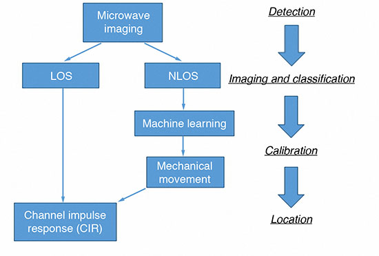
FIGURE 3. Proposed scheme for UWB localization in realistic environments with multipath situations.
There are four main phases of the operation. Firstly, the radar-based UWB microwave imaging system is introduced into the localization system to classify the LOS and NLOS environments. If the environment is LOS, the system will go to the location phase directly. If the environment is NLOS, further operations for the antenna array configuration need to be carried out to reduce the multipath effect from the non-target object. In this case, the only located target is the pair of wearable tag antennas.
Secondly, the system moves to the imaging and classification phase involving the Vivaldi antenna array on the anchor station. Using UWB impulses for MWI, the imaging system can detect the existence of inhomogeneity within a structure or medium and a two-dimensional (2D) image can be developed as shown in FIGURE 4.
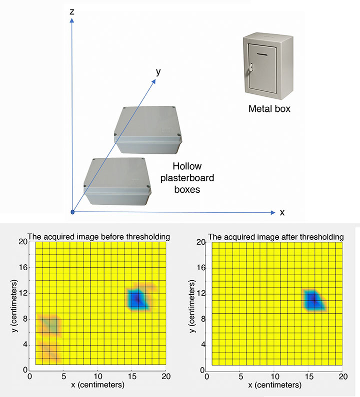
FIGURE 4. (Top) Layout of test setup. (Bottom left) The acquired imaging on shoulder plane before thresholding. (Bottom right) After thresholding.
During the imaging process, one wearable antenna is transmitting a Gaussian pulse while the other is receiving the scattered signals. Circular synthetic aperture radar (CSAR) and elevation-CSAR (E-CSAR) are widely used approaches to extract 2D spatial information of the imaging scenario and have been used for small area 2D remote sensing and foliage target detection. For our current work, we have adopted the CSAR approach. We developed Matlab code to process the data and generate images.
Various material obstructions such as hollow plasterboard boxes, solid concrete items and metal boxes were investigated during our experiments. We had to define threshold values for the various materials to get a more visually acceptable image.
According to the experiments, metal has a significant effect in NLOS environments, and the threshold value was used to optimize the final imaging result (a 20-pixel by 20-pixel image). The scanned area could be visualized with the imaging results depending, in part, on the heights of the antennas on the anchor station and the threshold value used. In this case, two hollow plasterboard boxes are filtered out, leaving the metal box in the image as shown in Figure 4(c).
In the third phase of the operation, the image result is fed into the machine learning algorithm used in the calibration phase. A pre-defined geometry of the antennas on the anchor stations, such as the six anchor stations in a cuboid shape, Y-shape or L-shape, was chosen for implementation in the current environment. The height and angle of the anchor antenna array pattern were adjusted using motors controlled by the NI MyRIO board. In this scenario, all the antennas on the anchor station are receivers (Rxs), and only body-worn antennas are transmitters (Txs).
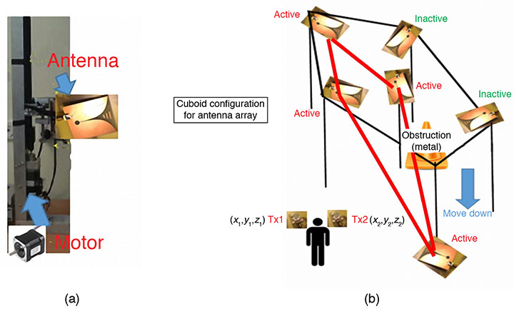
In this particular experiment, the obstruction (the metal box) is detected on the right upper side of the scanning area, so the cuboid configuration was selected as the anchor station setup. Four antennas on the left of the area were selected as receiving antennas as shown in FIGURE 5. Figure 5(a) highlights one of the antennas.
FIGURE 5. (a) Setup of anchor station. (b) Pre-defined geometry setup for anchor stations used for the experiment of Figure 4.
Finally, in the fourth (location) phase, the time of arrival of the signal from the transmitting antenna array at the receiving wearable antenna is estimated by channel impulse response (CIR) and peak detection techniques. An inverse fast Fourier transform (IFFT) is then applied to obtain the impulse response of the measured channels. The channel impulse response is given by:
where δ is the Dirac delta function, K is the number of resolvable multipath components, τk are the delays of the multipath components, ak are the path amplitude values, and θk are the path phase values. The MyRIO board controls the RF switch to circulate each receiving antenna and the corresponding S-parameter value (S21) is passed through the GPIB-to-USB cable for storage in the personal computer. The CIR, a peak detection technique and a TOA data-fusion method are used to accurately estimate the target’s location (xm, ym). Let (xi, yi) represent the position of the ith transmitting antennas, and r represent the range value obtained from the TOA measurement:
RESULTS
Let us summarize the procedure we followed for an experimental test of our proposed approach as described in the previous section. Our hardware setup is shown in Figure 1, and we carried out the experiment to demonstrate performance in both LOS and NLOS environments. Firstly, a 2D image of the scene area was reconstructed using the time-varying backscattered intensities as shown in Figure 4.
Secondly, the image is processed based on a database to detect the dielectric constants of the obstructions. The shape of the obstruction might not be completely delineated as the low resolution of the image favors an increased efficiency of the imaging processing. However, the position of the obstruction can be found whether it is on a critical path or not. Thirdly, the proper archor-station setup is implemented using the MyRIO board to control the RF switch and antenna motors according to a pre-defined database in the personal computer. Lastly, the peak detection algorithm is used to estimate the TOA of the UWB signal from the Tx at the Rx. The TOA is directly estimated by the detection of the strongest peak of the CIR.
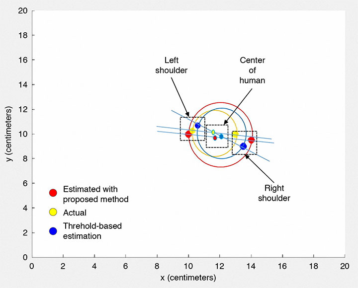
FIGURE 6 shows the localization results for the situation in Figure 4. The same experimental method was repeated but using a threshold-based TOA estimation procedure, and the results compared with our procedure. The results using that approach are also displayed in Figure 6.
FIGURE 6. UWB localization: estimated and actual positions of the antennas placed on the body for the environment as shown in Figure 5.
In TABLE 1, we summarize the localization errors obtained in the different environments using the two estimation techniques. The average accuracy achieved for our proposed approach for a single antenna is in the range of 3 to 5 centimeters. Given that there are two sensing antennas, one on each shoulder, we could establish a middle point as the position of the human body, and combining the results of each antenna, we could improve the accuracy to about 2.5 centimeters in the NLOS environment.
TABLE 1. Average localization error in centimeters for different testing environments with different estimation methods.
The method accuracy depends on the pre-defined solution for the anchor antenna array in the NLOS environment, and the estimation accuracy could be improved by training the hardware during the operating period. Furthermore, the localization accuracy also can be enhanced by increasing the number of active anchor stations. However, this will cost more in terms of hardware implementation and also require more space for the apparatus.
CONCLUSIONS
This article presents a hybrid UWB technique combining radar-based microwave imaging and localization of a body-worn UWB antenna for mapping 2D environments. We provided an overview of the concept and method of detecting obstructions, and described a sample implementation that proved the concept and provides ideas for further improvements.
Our results demonstrate the usefulness of the proposed technique, which provides similar performance regarding computational load and accuracy compared to traditional methods using a threshold-energy-based algorithm such as the search-back method and least-edge detection methods. The technique also is able to distinguish between LOS and NLOS environments.
Our approach has some advantages compared to the common methods for NLOS location. One advantage is the reuse of the anchor station for the microwave imaging setup to get low-resolution results for calibration. In addition, the reconfigurable anchor-station setup could be suitable in any NLOS environment with the predefined database. The database could also be improved even after the hardware system is set up. Furthermore, since the radar-based UWB microwave imaging technique uses a short pulse of low-power microwaves in the frequency range 3 GHz to 10 GHz, the measured scattered signal in the far-field can be used for imaging specific material according to its dielectric constant.
However, since the power level of the signal is limited, in part due to safety regulations, it is only detected over a short distance. The UWB pulse has a large bandwidth and, as such, the reflected signals contain a significant amount of information about the target for further imaging applications. Moreover, the anchor-station configuration model can be scaled by a factor suitable for the dimensions of any room or area under observation for a variety of indoor location applications.
A couple of important points to note is that although it is a radio technique, UWB is license-free because of its low power, and UWB technology’s carrier-less transmission property offers the advantage of simple and compact hardware.
Importantly, the performance of our proposed technique achieves more accurate localization of humans, for example, by using two body-worn transmitting antennas, one on each shoulder. The reconfigurable hardware structure under computer control provides the potential for a self-upgrading platform for indoor positioning with a more appropriate anchor-station setup being achieved using machine learning technology.
ACKNOWLEDGMENTS
The authors thank Iain Gold of the School of Engineering, University of Edinburgh, for his help in the fabrication and measurements of the antennas. The authors also acknowledge the Scottish Microelectronics Centre at the University of Edinburgh for measurement equipment support. This article is based on the paper “Localisation of Wearable Ultra-wideband Antenna for Indoor Positioning Application” presented at ION GNSS+ 2017, the 30th International Technical Meeting of the Satellite Division of The Institute of Navigation, Portland, Oregon, Sept. 25–29, 2017.
FENGZHOU WANG received a B.S. (Hons.) degree in electrical engineering from Birmingham City University in England, and an M.S. degree from the University of Southampton, England. He is working towards a Ph.D. degree in the School of Engineering, University of Edinburgh, Scotland. His research addresses the area of RF sensor systems design and integration.
GUOHUA WANG received his B.S. degree in machinery design and manufacture from Southwest Agricultural University, Chongqing, China; an M.S. degree in agricultural mechanization engineering from China Agricultural University, Beijing, China; and a Ph.D. degree in measurement technology and instrumentation from Beihang University, Beijing, China. He is a lecturer in the School of Instrumentation and Opto-Electronic Engineering in Beihang University. His research interests include automatic testing and partially reconfigurable systems.
“Hybrid Positioning with Smartphones” by J. Liu in Ubiquitous Positioning and Mobile Location-Based Services in Smart Phones, edited by R. Chen, published by IGI Global, Hershey, Pennsylvania, 2012, pp. 159–194.
Ubiquitous Positioning by R. Mannings, published by Artech House, Norwood, Massachusetts, 2008.
“Non-GPS Navigation for Security Personnel and First Responders” by L. Ojeda and J. Borenstein in Journal of Navigation, Vol. 60, No. 3, September 2007, pp. 391–407, doi: 10.1017/S0373463307004286.
• Ultra-Wideband Positioning
“Comparing Ubisense, BeSpoon, and DecaWave UWB Location Systems: Indoor Performance Analysis” by A.R.J. Ruiz and F.S. Granja in IEEE Transactions on Instrumentation and Measurement, Vol. 66, No. 8, pp. 2106–2117, August 2017, doi: 10.1109/TIM.2017.2681398.
Ultra-wideband Positioning Systems: Theoretical Limits, Ranging Algorithms, and Protocols by Z. Sahinoglu, S. Gezici and I. Guvenc, published by Cambridge University Press, Cambridge, U.K., 2008.
“Prior Models for Indoor Super-resolution Time of Arrival Estimation” by D. Humphrey and M. Hedley in Proceedings of VTC Spring 2009, the 69th Vehicular Technology Conference, Barcelona, Spain, April 26–29, 2009, 5 pp., doi: 10.1109/VETECS.2009.5073817.
“Ranging with Ultrawide Bandwidth Signals in Multipath Environments” by D. Dardari, A. Conti, U. Ferner, A. Giorgetti and M.Z. Win in Proceedings of the IEEE, Vol. 97, No. 2, February 2009, pp. 404–426, doi: 10.1109/JPROC.2008.2008846.
“A New Time of Arrival Estimation Method Using UWB Dual Pulse Signals” by R. Zhang and X. Dong in IEEE Transactions on Wireless Communications, Vol. 7, No. 6, June 2008, pp. 2057–2062, doi: 10.1109/TWC.2008.070112.
“Threshold-based TOA Estimation for Impulse Radio UWB Systems” by I. Guvenc and Z. Sahinoglu in Proceedings of ICU 2005, IEEE International Conference on Ultra-Wideband, Zurich, Switzerland, Sept. 5–8, 2005, pp. 420-425, doi: 10.1109/ICU.2005.1570024
Ultrawideband Antennas for Microwave Imaging Systems by T.A. Denidni and G. Augustin, published by Artech House, Norwood, Massachusetts, 2014.
“The Vivaldi Aerial” by P.J. Gibson in Proceedings of the 9th European Microwave Conference, Brighton, U.K., Sept. 17–20, 1979, pp. 101–105, doi: 10.1109/EUMA.1979.332681.
• Characteristics of Antennas and Their Interaction with Humans
An independent technical review published earlier this month found sufficient data in three government-conducted tests to assess the risk of using frequencies near the GPS band for a ground-based communications network — specifically, the one proposed by Ligado Networks. The panel rejected two tests sponsored by Ligado Networks, saying they did not meet minimum criteria for inclusion or use.
The testing and various hearings before the Federal Communications Commission (FCC) come in response to increasing demand for commercial spectrum to support broadband wireless communications. The FCC and other branches of U.S. government are giving serious consideration to repurposing various radio frequencies, including the satellite communications bands next to GPS, to accommodate this.
Ligado Networks has petitioned the FCC to repurpose satellite frequencies near GPS to also support terrestrial telecom services, effectively transferring its license for space-based broadcasting to powerful terrestrially-based broadcast towers. Ligado’s custom networks would provide services for industrial operations such as power grids and connectivity for drones and driverless cars, in addition to consumer broadband services.
The National Executive Committee of the government’s National Coordination Office for Space-Based Positioning, Navigation, and Timing released the assessment by its National Space-Based PNT Systems Engineering Forum (NPEF) of testing methodologies used to analyze the impacts of adjacent band interference on GPS receivers. The assessment is also known as the “gap analysis.”
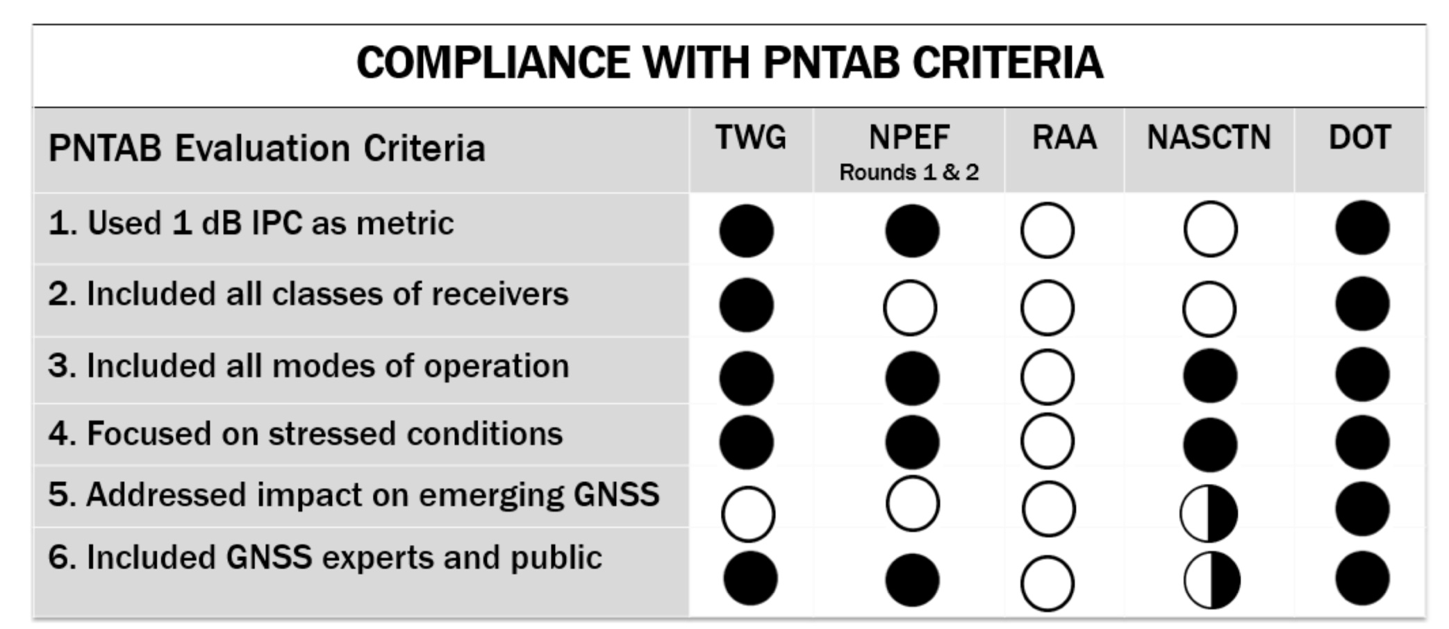
The NPEF evaluated five tests performed by the following organizations, the first three of them government organizations and the last two private tests sponsored by Ligado with little or no public or government input:
Federal Communication Commission (FCC)-mandated Technical Working Group (TWG) — done in 2011.
National Space-Based PNT Systems Engineering Forum (NPEF) — done in 2011.
Department of Transportation (DOT) Adjacent Band Compatibility (ABC) — done in 2017 but not previously released.
Roberson and Associates (RAA)
National Advanced Spectrum and Communications Test Network (NASCTN).
The gap analysis concluded that the results from the first three tests are sufficient and appropriate to inform spectrum policy makers on the major impacts of a proposed LTE network on GPS receivers. The DOT test results revealed the power levels that GPS and GNSS receivers can tolerate from interference sources in the adjacent band in an effort to inform the enforcement of a GPS interference protection criterion.
PNT Advisory Board’s set of minimum criteria. The two Ligado-sponsored tests are the RAA and the NASCTN. (Image: PNTAB)
The NPEF team found the scope and framework of the last two tests, sponsored by Ligado, to be insufficient when evaluated against the PNT Advisory Board’s set of minimum criteria. Key among these criteria is one that specifies use of the internationally accepted 1 dB degradation Interference Protection Criterion (IPC): a one-decibel (1 dB) degradation in C/N0, the carrier-to-noise power density ratio. Ligado has tried to redefine the standard measurement of interference to one more in its favor: a change in positioning and timing accuracy.
For further background on this and other aspects of the gap analysis, see the January 2018 GPS World article by Brad Parkinson, “A Grave Threat to GPS and GNSS.”
The NPEF strongly recommended that decisions impacting the GPS radio frequency environment be informed by data from tests that align with the PNTAB’s set of minimum criteria and with full consideration of the potential operational, scientific, and economic impacts.
The full gap analysis study can be downloaded here.
The NPEF is co-chaired by the Departments of Defense and Transportation and consists of representatives from at least 14 federal agencies.
STMicroelectronics has confirmed the validation of its LSM6DSL 6-axis inertial sensor and LPS22HB pressure sensor for the Alibaba internet of things (IoT) ecosystem, which enables users to create complete IoT nodes and gateway solutions with better time to market.
Launched in 2017, AliOS Things is a light-weight embedded IoT operating system developed by Alibaba. The company recently released AliOS Things v1.2, which includes a sensor-based component called uData.
The ST sensors that have passed the AliOS validation have been integrated in uData, and the two companies are cooperating on the development of IoT systems that aim to improve end-user experiences.
The LSM6DSL is a system-in-package featuring a 3D digital accelerometer and a 3D digital gyroscope that operates at 0.65 mA in high-performance mode and enables always-on low-power features for an optimal motion experience for the consumer.
According to the company, high robustness to mechanical shock makes the LSM6DSL the preferred choice of system designers for the creation and manufacturing of reliable products. The LSM6DSL supports main OS requirements, offering real, virtual and batch sensors with 4 Kbytes for dynamic data batching.
The LPS22HB is an ultra-compact piezo-resistive absolute pressure sensor that functions as a digital output barometer. Dust-free and water-resistant by design, the sensor enables high accuracy and low-power operation. It is available in full-mold package with silicon cap and six 20-µm holes guaranteeing sensor moisture resistance, relative accuracy of pressure measurement 0.1 mbar, and very low power consumption (12 µA in low-noise mode).
“The validation by Alibaba of ST’s LSM6DSL and LPS22HB sensors is an important achievement,” said Collins Wu, marketing director, Analog and MEMS Group, Greater China & South Asia, STMicroelectronics. “Creating and connecting nodes quickly and securely is facilitated by the holistic platform of AliOS, which cuts time to market for users and allows them to create IoT systems in China quickly for applications in smartphones, smart watches, smart locks, smart parking and beyond. On top of this, Alibaba is collaborating closely with ST to integrate more products in the platform, offering compelling IoT solutions for customers.”
Telit’s two latest modules are aimed at the European internet of things (IoT) market.
Modules WE866E4-P and ME910C1-E2 are designed to meet European specifications requirements, providing the ability to bring advanced IoT applications to market such as smart buildings, smart energy, industrial applications, medical devices and others.
“Our modules were designed with the European market in mind, eliminating the guesswork associated with what standard to use for IoT projects in the region,” said Yossi Moscovitz, Telit president of products and solutions. “We are providing the industry the ability to digitally transform by creating new opportunities for our customers to achieve innovation. We’re pleased to be a key part of enabling the promise of Smart IoT that we are seeing during this week’s conference.”
The WE866E4-P is a fully integrated dual-band, dual-mode combo Wi-Fi (802.11 a,b,g,n) and Bluetooth Low Energy (BLE) 5.0 module, with an small footprint (285 sq. mm) that provides a cost-effective way for manufacturers to add wireless connectivity to the products. It has an integrated tri-core system-on-chip with dedicated CPUs for IoT applications, Wi-Fi and BLE.
The module is self-contained with full Wi-Fi, BLE and TCP/IP networking stacks along with a complete suite of security features such as secured boot, Flash encryption, copy protection, HTTPS and WPA/WPA2 personal and enterprise security modes.
The ME910C1-E2 is a member of Telit’s flagship xE910 module family delivering 4G radio access technology in the 28.2 x 28.2 x 2.2 mm family form factor. This module increases the addressable market for LTE technology to include a broad range of new applications and use cases best served with lower maximum data rate, ultra-low power, reduced complexity and cost, and is capable of Cat M1, NB-IoT and 2G fallback. Examples of use are smart meters, industrial sensors, health-care monitors, home automation, asset tracker and other low-data-rate IoT devices.
For more information please visit Telit during this week’s Smart IoT Conference in London at Stand T2865.