XPeng Motors‘ new XPeng P5 smart electric vehicle is equipped with automotive-grade lidar technology. The P5 has “navigation guided pilot” (NGP) capabilities, which will be on China’s city roads for the first time in a production vehicle, powered by XPeng’s full-stack in-house developed autonomous driving system XPILOT 3.5.
The XPILOT 3.5 autonomous driving system has a high-precision positioning unit (GNSS + inertial measurement unit, or IMU) along with 32 perception sensors — two lidar units, 12 ultrasonic sensors, five millimeter-wave radars and 13 high-resolution cameras. The sensors are fused into a 360° dual-perception system to provide sufficient redundancy to handle challenging and complex road conditions.
The double-prism lidar units are able to distinguish pedestrians, cyclists and scooters, static obstacles, and road work, in challenging scenarios such as night and low-light conditions, backlighting and alternating light-and-dark illumination in tunnels.
Extending the NGP function from highways to city diving, the P5 will be able to handle situations such as other autos cutting in, automatic follow and speed-limit optimization on urban roads, recognizing traffic lights as well as small objects.
The P5’s Xmart OS 3.0 in-car operation system supports all-voice interaction. It uses Qualcomm’s Snapdragon SA8155P auto-grade computing platform to ensure seamless user control and interaction. The instrument console includes a 15.6-inch screen with essential information and controls where the driver needs them. Xmart OS 3.0 also allows vehicle-to-home connection.
The P5 will be featured at Auto Shanghai 2021 on April 19.
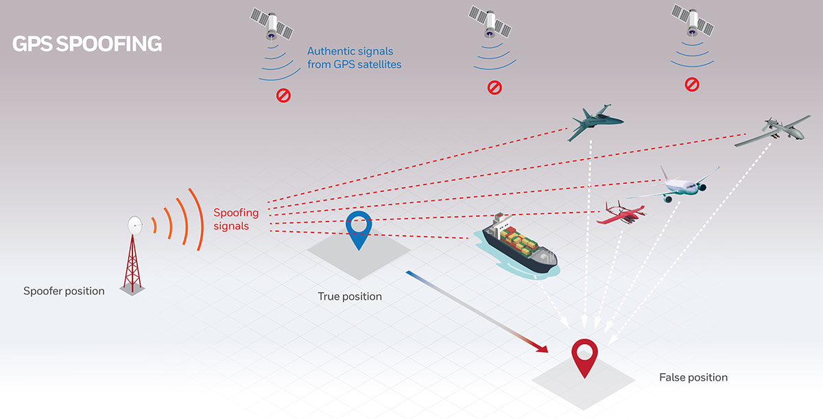
New technologies use a variety of inputs to help ensure seamless navigation, even when GPS reception fails because of interference or jamming.
Honeywell has successfully demonstrated multiple alternate navigation technologies for military aircraft. These new products are intended to help ensure seamless navigation — even when GPS signals are blocked, interrupted or unavailable.
For military operations, GPS-jamming — intentional or not — can block vital signals from conveying critical information regarding positioning, navigation and timing (PNT). In these instances, it’s important for military vehicles and aircraft to be equipped with alternative navigation technologies, like celestial or vision navigation, to maintain operational readiness.
“For military operations, not having access to critical positioning and timing information can make or break a mission,” said Matt Picchetti, vice president and general manager, Navigation & Sensors, Honeywell Aerospace. “We’re very excited to roll out this robust lineup of alternate navigation solutions, which are specifically designed to address the needs of our military customers and give them the added layers of redundancy needed to successfully carry out their operations, even if they lose access to GPS signals.”
Illustration: Honeywell
Alternate navigation technologies provide a different means of measuring position, velocity and heading when GPS is disrupted. These technologies include:
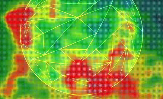
Vision-aided navigation. This technology uses a live optical or infrared camera feed and compares it with maps to provide a passive, not jammable, highly accurate alternative PNT solution that provides GPS-like accuracy in GPS-denied or jammed conditions.
Celestial-aided navigation. Honeywell’s celestial-aided navigation technology observes stars and “reference objects” orbiting the earth such as satellites, which have known positions and velocities. This technology compares those reference objects to stars and can determine position and velocity, the same way a GPS receiver can.
Magnetic anomaly-aided navigation. This navigation technology measures magnetic strength using sensors and compares this data with known geographical magnetic maps to accurately identify the position of the aircraft relative to the Earth.
Prototypes of these alternate navigation systems will be available in 2022, with initial deliveries expected to start in 2023.
Honeywell navigation systems are used by nearly every aircraft flying to guide millions of passengers to their destinations. Since 1914 when the first autopilot used Honeywell gyroscopes to hold the plane stable during flight, Honeywell has delivered more than 500,000 high-performance inertial sensors across several platforms on land, in the air and at sea.
GTX Corp will begin testing its new Cat M1 LTE SmartSoles across North America, Europe and Australia, and will begin the regulatory certification process for FCC/IC and CE.
The following week will begin the device network certification with Verizon, which will be providing the cellular connectivity for the North American market. GTX will also be testing with Orange and Telefonica for connectivity in Europe and Australia.
“With over 200 back orders and increasing demand every day, we intend to begin production as soon as we complete testing and certification, expected sometime next month, and then immediately start fulfilling all pre-orders and backorders first,” said Andrew Duncan, GTX Corp. director.
The patented and award-winning GPS SmartSoles were designed to address Alzheimer’s and autism challenges, where those diagnosed are at risk of wandering and becoming lost. Wandering is a safety issue with far-reaching implications for the person with the disease, their caregiver, law enforcement and healthcare providers.
GPS SmartSoles are placed in the wearer’s shoes. They contain a Nordic Cat M1 LTE GPS module connected through cellular networks that send a GPS location to the GTX central monitoring website and app. GTX is also upgrading its tracking app both for iOS and Android.
The SmartSoles can also be used by people at risk of kidnapping, such as government employees, journalists and corporate executives. SmartSoles come in three trim-to-fit sizes for men, women, and children, are water resistant, include an inductive charging pad, and are assembled in Rhode Island.
Hyper Precise Location (HPL), a real-time kinematics (RTK) service, is now available via Verizon ThingSpace to customers and application developers in more than 100 U.S. markets. When paired with Verizon’s 5G Edge capabilities, HPL provides precise positioning data for emerging cellular-vehicle-to-everything (C-V2X) technology, which is necessary for certain safety applications.
Verizon recently teamed with automakers to demonstrate vehicle-pedestrian safety scenarios made possible through HPL, 5G Edge and C-V2X.
HPL is software as a service (SaaS) that provides a stream of real-time GNSS correction data to device receivers, enabling location accuracy within 1-2 centimeters, for users on 5G and 4G networks. This can enable high-scale, low-cost, centimeter-level location capabilities for industries such as automotive, HD mapping, robotics, construction, and smart agriculture (AgriTech). Designed and deployed in a privacy-protective manner, HPL does not store or share user location data.
HPL embraces open delivery standards including RTCM for its data streams, with others to be added on a rolling basis. IoT devices using HPL can be accessed and managed through a user API and the ThingSpace IoT management platform. Support resources on ThingSpace will detail API integration, coverage availability, and more.
“Hyper Precise Location stands to boost or enable next-gen technologies across industries, from intelligent-driving to drone delivery to highly automated operations within construction, agriculture, and much more,” said TJ Fox, SVP of Industrial IoT and automotive for Verizon Business. “HPL’s fast expanding coverage area, API friendliness, privacy protection, and use of open-delivery standards make it ideal for developers and customers demanding precision and flexibility.”
In August, Verizon announced it is also developing HPL next-gen road safety and highly advanced driving solutions through partnerships with location and mapping expert HERE Technologies (HERE) and Renovo, the automotive software company. HPL can also support other emerging technologies that depend on high-level location accuracy, such as delivery drones, and advanced IoT applications, such as infrastructure monitoring, critical asset tracking, and high value shipping.
Firefighters in Slovenia. (Photo: tomazl/E+/Getty Images)
Public Safety Communication Europe (PSCE) and the European Space Agency (ESA) have signed a Memorandum of Intent (MoI) to support the use of satellite applications for public safety.
ESA and PSCE will work together under the new MoI towards establishing interoperable public safety communications systems.
The MoI will support the emergence of space-based applications in the public-safety domain such as public safety services relying on secure mobile broadband communication solutions. These include applications within disaster preparedness, response and resilience, situational awareness, assessments of damages, navigation-based services for tracking and coordinating rescue forces on-site and for emergency vehicles.
“ESA Space Solutions and the 4S Strategic Programme Line will support through this agreement the emergence of solutions making use of secure satellite communications for institutional public safety user communities,” said Rita Rinaldo, ESA. “This can be achieved as of today through existing satellite telecommunications infrastructures. In the future it will be possible to make use of new and innovative infrastructures with enhanced capabilities. Early pilots and demonstrations will showcase the unique benefits granted by satellites to the user communities and early adopters.”
“The cooperation with ESA will help to explore complementary solutions that will contribute to cover capability gaps and needs for public safety. It is of extreme importance to improve public safety communication systems with cutting-edge and rapidly deployable solutions that will facilitate PPDR missions,” explained Marie-Christine Bonnamour, PSCE.
The first step for ESA and PSCE cooperation will be PSCE participation in ongoing user studies on “Satellite Applications for Public Safety.” PSCE will help identify the needs of public safety stakeholders such as emergency services, fire brigades and law enforcement.
Trimble to provide reliable in-lane positioning for the year-long research program
Trimble and VSI Labs have formed an alliance, with Trimble serving as the GNSS precise positioning supplier for VSI’s autonomous research vehicle program. The alliance officially kicked off in March at Destination ACM, a long-distance driving event for VSI’s research vehicle that continues with additional events throughout the year.
The collaboration provides the opportunity to showcase Trimble RTX technology as the trusted precise-positioning correction source for car manufacturers and their suppliers. Coupled with Trimble’s inertial positioning, Trimble RTX plays a pivotal role in a vehicle’s ability to maintain accurate and reliable lane-discipline during autonomous driving.
Destination ACM launched from VSI’s Minneapolis headquarters en route to the American Center for Mobility’s (ACM) test center in southeast Michigan where a day of testing and demonstration took place March 26.
“The integration of Trimble’s precise RTX positioning is a key element of VSI’s technology stack for advanced driver assistance systems (ADAS) and autonomous vehicle (AV) applications,” said Stephen Ruff, general manager of Trimble’s On-Road Autonomy Division. “VSI Labs is a leading researcher of best-in-class technologies critical to autonomous vehicle development.”
Suitable for on-road driving applications, Trimble RTX corrections operate on a single, global network. Drivers are not subject to the coverage outages that can exist when relying on local positioning systems — requiring line-of-sight to a positioning source or radio/cellular/internet connections.
When occasional obstructions are present, such as a bridge, tunnel or deep urban or rural canyon, Trimble augments its precise GNSS positioning with inertial technology to maintain continuous positioning and orientation while on the road.
Trimble’s innovative GNSS positioning is being used on the road today by a number of automotive OEMs and Tier 1 suppliers to improve the functional safety and performance of ADAS for passenger vehicles. Consumers have logged more than 7 million miles using Trimble RTX for lane-level positioning to date.
“VSI Labs is thrilled to have Trimble’s RTX technology on board,” said Phil Magney, founder and president of VSI. “Trimble’s positioning capabilities allow us to really expand our applied research on the safety and performance of autonomous and ADAS driving solutions.”
Trimble GNSS positioning technology will be used in the VSI research vehicle during each of the quarterly Destination ACM events, the Drive World Conference in Silicon Valley in August, the VSI 2021 “Drive South,” and other events this year.
For more about autonomous vehicles, see our June issue.
Inertial Labs has released a new generation of GPS-aided inertial navigation systems (INS) for applications such as UAVs, helicopters and lidar surveys.
The company also has released two new inertial measurement units (IMUs) for measuring angular rates and accelerations for motionless and dynamic applications.
INS-DH-OEM
The INS-DH-OEM. (Photo: Inertial Labs)
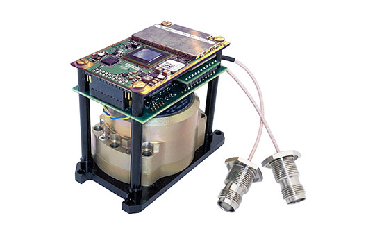
The high-accuracy INS-DH-OEM is designed for easy integration into custom enclosures and higher order integrated system applications. It combines the HoneywellHG4930 inertial measurement unit (IMU) into a GPS-aided INS to provide high-accuracy orientation, position, velocity and timing for land and aerial systems.
Consisting of three axes each of high-precision accelerometers and gyroscopes, the accuracy of the HG4930 plays a key role in the exceptional performance of the INS-DH-OEM. With input from the IMU, the INS-DH-OEM has a pitch-and-roll accuracy of 0.015 degrees real-mean-squared (RMS) for dynamic applications, and a pitch-and-roll accuracy of 0.01 degrees for motionless applications.
Another key factor for the INS-DH-OEM is its use of the NovAtelOEM7720 dual-antenna GNSS receiver. The OEM7720 is an all-constellation, multi-frequency heading and positioning solution with TerraStar PPP correction services and advanced interference mitigation features.
With aiding data from the OEM7720, the INS-DH-OEM features a 2-meter baseline heading accuracy of 0.05 degrees RMS for both static and dynamic applications. As a result, the INS-DH-OEM is a high-performance solution in line-of-sight and beyond line-of-sight antenna-pointing applications.
A reliable solution in varying environments, the OEM7720 ensures that the INS-DH-OEM is outputting the most accurate GNSS-aided data by supporting GPS, GLONASS, BeiDou, Galileo, NavIC (IRNSS), and QZSS constellations.
The INS-DH-OEM can be applied in a wide range of aerial applications such as remote sensing, flight control and photogrammetry in which the INS-DH-OEM provides accurate positioning, navigation and timing (PNT) data for multi-rotor drones, fixed-wing drones and other UAVs performing these tasks. This data is paramount in the accuracy of these applications’ deliverables such as point clouds, orthomosaics and photogrammetric plots.
Weighing 280 grams and measuring 85.7 x 62.5 x 52.0 mm, the INS-DH-OEM is a lightweight, compact system that can be fitted with custom enclosures or integrated into higher order systems such as lidar payloads. It is compatible with scanners from many lidar manufacturers: Livox, Velodyne, Ouster and Quanergy. This adaptability, coupled with top-of-the-line subcomponents and Inertial Labs’ sensor-fusion expertise, make the INS-DH-OEM the suitable for UAVs, UGVs, antenna pointing, and many more applications.
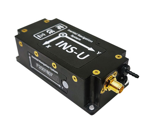
INS-U
The INS-U. (Photo: Inertial Labs)
The new INS-U GPS-aided INS with air data computer (ADC) output signal is based on a u-blox module.
The INS-U a fully integrated INS, attitude and heading reference system (AHRS), IMU and air data computer high-performance strapdown system that determines position, navigation and timing information for any device on which it is mounted.
The INS-U utilizes a single antenna, multi-constellation U-Blox GNSS receiver. With access to GPS, GLONASS, Galileo, QZSS, and BeiDou, the INS-U can be used in a variety of GPS-enabled environments and is protected against spoofing and jamming. Additionally, the INS-U is comprised of two barometers, a miniature gyro-compensated fluxgate compass, and tri-axis temperature calibrated advanced MEMS accelerometers and gyroscopes. These high-performance sensors, along with Inertial Labs’ new on-board sensor fusion filter, state of the art guidance and navigation algorithms, provide accurate position, velocity, and orientation of the device under measure.
Perhaps the most defining feature of the INS-U is its embedded ADC. An essential avionics component for modern UAV applications, an ADC outputs static & dynamic pressure, pressure altitude, calibrated & true airspeed, true angle of attack, rate of climb, and wind speed of the device under measure. This data, combined with inertial reference information, provides UAVs with accurate information about the unit and its relation to its environment.
By using data from an INS, AHRS, IMU and ADC, the INS-U provides a complete navigation solution for UAV and Helicopter applications. The unit can use time-of-flight aiding data from a ground station for long term GNSS-denied conditions as well as external position and heading so it can still output accurate PNT information regardless of the environment.
The INS-U is a lightweight and compact solution with dimensions of 82 x 40 x 26 mm and a weight of less than 200 grams. This, along with an IP67 environmental enclosure, ensures that the INS-U can meet the environmental requirements and size and weight restrictions of a wide range of applications.
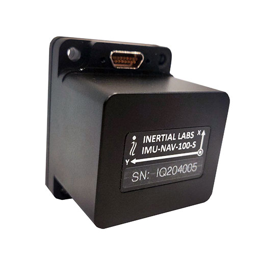
IMU-NAV-100
The IMU-NAV-100. (Photo: Inertial Labs)
The IMU-NAV-100 is a tactical grade IMU for wide range of higher order integrated system applications.
The newest addition to the Inertial Labs Advanced MEMS sensor-based family, the IMU-NAV-100, is now the best performing IMU that Inertial Labs offers. The IMU-NAV-100 is a fully integrated inertial solution that measures linear accelerations, angular rates, and pitch and roll with high accuracy utilizing three-axis high-grade MEMS accelerometers and three-axis tactical grade MEMS gyroscopes.
The IMU-NAV-100 features continuous built-in test, configurable communications protocols, electromagnetic interference protection, and flexible input power requirements which allow it to be easily integrated in a variety of higher order systems.
The IMU-NAV-100 line contains two options to accommodate a variety of projects.
The IMU-NAV-100-S is best for projects that require high performance stabilization for antenna and line-of-sight stabilization systems, motion control sensors, and platform orientation and stabilization systems. With a gyroscope angular random walk of 0.04 deg/√hr, the IMU-NAV-100-S is specialized to provide accurate data for stabilization applications.
The IMU-NAV-100-A is best used in a variety of systems such as GPS-aided INS, AHRS, and motion reference units. Regardless of the application, the IMU-NAV-100 is the company’s best performing IMU to date, providing a pitch-and-roll accuracy of 0.03 deg RMS. Fully calibrated, temperature compensated, and mathematically aligned to an orthogonal coordinate system, the IMU contains up to 0.5 deg/hr bias in-run stability gyroscopes and 0.003 mg bias in-run stability accelerometers with very low noise and high reliability.
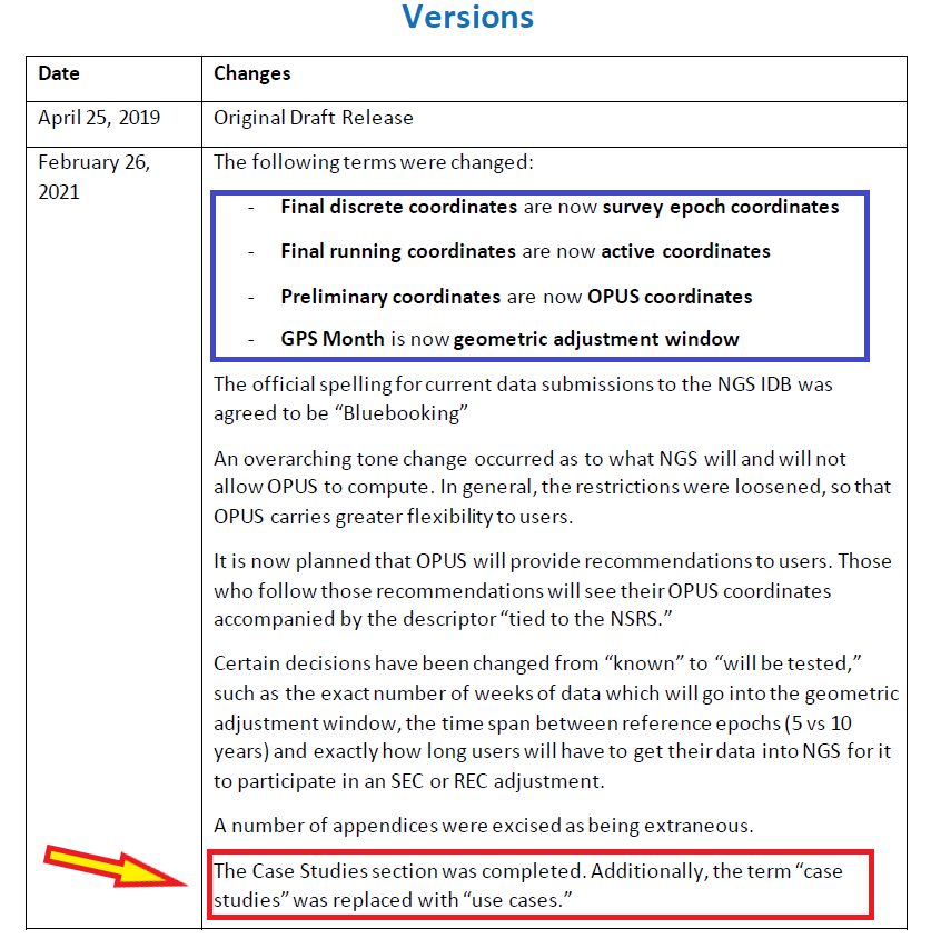
The National Geodetic Survey (NGS) has revised an important technical document on the modernized National Spatial Reference System (NSRS). Zilkoski explores a use case on flood mapping, discussing an Elevation Certificate example, Flood Insurance Rate Map and Flood Insurance Study. NGS has scheduled a webinar for April 8 to discuss the four use case examples.
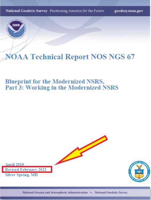
In February 2021, the National Geodetic Survey (NGS) revised NOAA Technical Report NOS NGS 67 Blueprint for the Modernized NSRS, Part 3: Working in the Modernized NSRS. Users can download the publication. See the box titled “NOAA Technical Report NOS NGS 67.”
This column will highlight one of the four use cases: “Use Case 1: Flood Mapping.” The case study discusses the Elevation Certificate (CE) example, Flood Insurance Rate Map (FIRM), and Flood Insurance Study (FIS).
The following is the scenario that NGS considered in this use case:
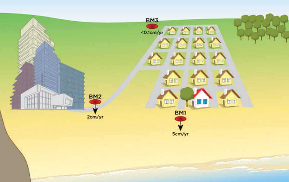
“This use case’s examples are set in an imaginary flood-prone coastal community experiencing non-uniform ground subsidence at the watershed scale (see Figure 10). Although many areas are not subject to this level of vertical motion, the full benefits of NSRS modernization are most apparent in this context. We illustrate differences in the use of the NSRS of today and the modernized NSRS with two common NFIP workflows. First, we consider steps anticipated in the certification of NAPGD2022 elevations for a NFIP Elevation Certificate. Second, we step into the shoes of a FEMA Mapping Partner to examine the ways future NSRS tools support more accurate mapping in Flood Insurance Rate Map (FIRM) and Flood Information Study (FIS) updates.”
I think this is a good scenario to use to demonstrate the full benefits of the NSRS modernization in areas of subsidence, but I believe there are important issues that will need to be addressed before the implementation of NAPGD2022 in flood mapping projects. I will highlight some of these issues later in the newsletter. First, let’s look at NGS example.
As depicted in figure 10 in NOS NGS 67 technical document, the area has three difference subsidence rates (<0.1 cm/yr., 2 cm/yr., and 5 cm/yr.). See the box titled “Diagram of fictional case study location for Use Case 1.” As NGS stated in the document, “Although many areas are not subject to this level of vertical motion, the full benefits of NSRS modernization are most apparent in this context.”
This may not be the typical situation of a flood mapping project but it should be noted that this type of high individual rates and large relative rate differences has occurred in the Houston-Galveston, Texas, region (see the following publications):
NGS’s example illustrates differences in the use of the NSRS today and the future NSRS with two common National Flood Insurance Program (NFIP) workflows. The example addresses surveyors performing a FEMA Elevation Certification using NAPGD2022 elevations, and the ways future NSRS tools support more accurate mapping in Flood Insurance Rate Map (FIRM) and Flood Information Study (FIS) updates.
It should be noted that according to the September 27, 2017, Office of Inspector General Department of Homeland Security OIG-17-110 report, FEMA’s goal is to review flood maps every five years.
“According to the National Flood Insurance Reform Act of 1994, FEMA must assess the need to revise and update all floodplain areas and flood risk zones identified once during each 5-year period. Thus, valid miles will expire every five years if not assessed. Failure to assess an NVUE compliant mile within the 5-year window will result in the mile being re-categorized as “Unknown” in the Needs Database. Unknown miles have not been subjected to the validation process to determine whether they reflect the current flood risk or are in need of restudy. In 2009, FEMA set a goal to attain 80 percent NVUE by the end of fiscal year 2014.” — Excerpt from Department of Homeland Security OIG-17-110 report
The modernized NSRS will help facilitate meeting this goal. This is described in NGS’s use case example:
NFIP products will primarily utilize the official NSRS reference epochs
“As the NFIP is structured today, NFIP products will primarily utilize the official NSRS reference epochs. Additionally, some NFIP products such as the EC form itself, as well as guidance, and technical references for FIRM and FIS preparation would benefit from updates that reflect changes to the NSRS. While the time-dependency and incorporation of a gravimetric geoid model will manifest as improved risk assessment reliability in inundation map products, we notably anticipate that NSRS modernization will have a limited impact on the basic structure of most recommended workflows associated with the NFIP of today. The most significant development is therefore the opportunity for FEMA’s National Flood Mapping Program (NFMP) to increasingly leverage the new capabilities of the NSRS to ensure that current, accurate ground elevation data is used, and to better incorporate relevant flood control structure and future conditions mapping data to support decision-making beyond the NFIP. Details of how the modernized NSRS can help FEMA achieve broader NFMP objectives and opportunities for data-driven case studies to explore this are described at the end of the use case.”
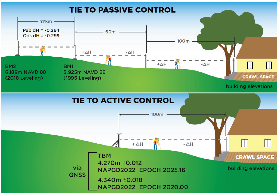
So, what does this really mean? The document uses two diagrams to explain how the new NSRS would be used to estimate a height for a FEMA Elevation Certificate (see box titled “Figure 11 from Use Case 1”). The top cartoon labeled “Tie to Passive Control” describes the process being performed today. That is, a surveyor locates the two closest marks that have published orthometric heights, follows the appropriate surveying procedures to ensure that the marks have not moved since the last time they were leveled to, and then performs the appropriate procedures to obtain the height for the Elevation Certificate. Depending on the location of the published orthometric heights in the area of the structure, this process could be very expensive. The lower cartoon labeled “Tie to Active Control” describes the process that will be used in the modernized NSRS using NADGP2022 heights. The user would occupy a temporary mark near the structure with GNSS to obtain a NAPGD2022 orthometric height computed using the appropriate ellipsoid height and geoid height value, and then perform the appropriate leveling procedures to obtain the height for the Elevation Certificate. This process will provide the most up-to-date height in the area.
Figure 11 from Use Case 1. Cartoon of Elevation Certificate field surveys based on establishing a tie to the NSRS via passive control leveling (top panel) and via active control with GNSS (lower panel). (Image: NGS)
There is an issue that should be noted here: the temporary mark determined using active control may provide the most up-to-date height at a particular location but that height may not be consistent with the heights used to establish the Base Flood Elevation (BFE). At first, someone would say, that’s good because it’s indicating that the flood hydraulics have changed on the floodplain map. However, without performing a detailed height analysis in the region, the user won’t really know whether the BFE value should be updated based on the current changes in topography in the floodplain region. In other words, if the entire region has subsidence at the same rate then the relative height difference hasn’t changed, and the new starting height may not be consistent with the published BFE on the FEMA Floodplain Map. In most floodplain mapping regions, the changes in heights are probably less than the accuracy of the maps but using the height of a mark that is not consistent with the BFE could place a homeowner’s house incorrectly in a flood zone. A good surveying practice would include occupying several marks with GNSS (or leveling between marks) that were involved in the creation of the flood insurance study and the generation of the floodplain map to ensure that the height used on the Elevation Certificate is consistent with the BFE. This is a good procedure to use for the current NSRS as well as the modernized NSRS. However, this is not economically practical using the current NSRS but could be in the new NSRS which is a major benefit of the modernized NSRS.
So, let’s look at the Houston-Galveston region using the latest information available.
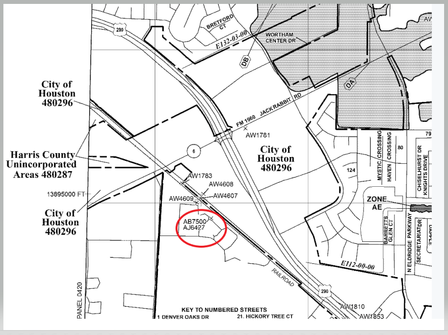
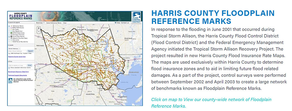
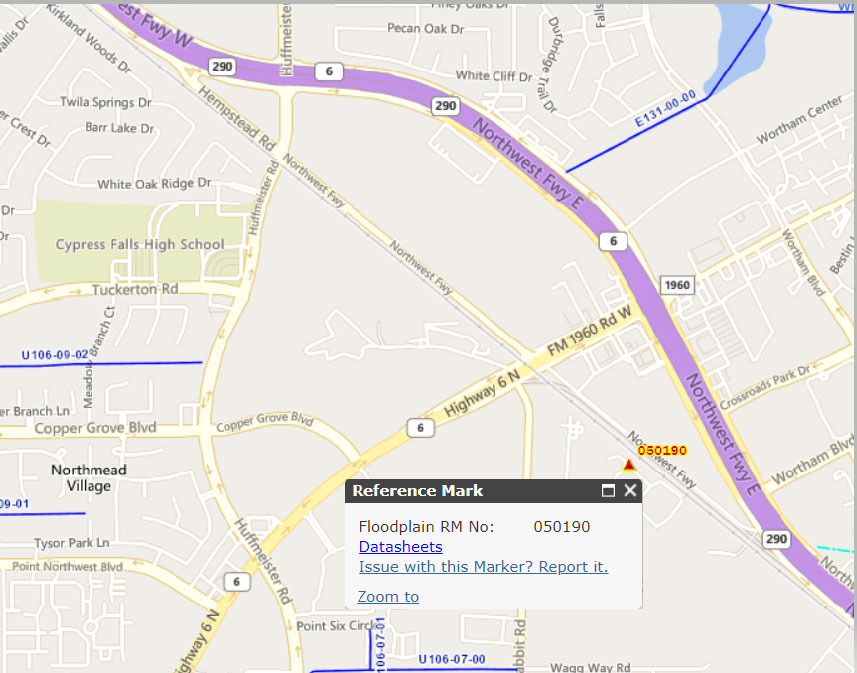
The box titled “Snapshot of Vertical Control from Harris County Floodplain Reference Marks Website” depicts the location of one of the reference marks, denoted as 050190.
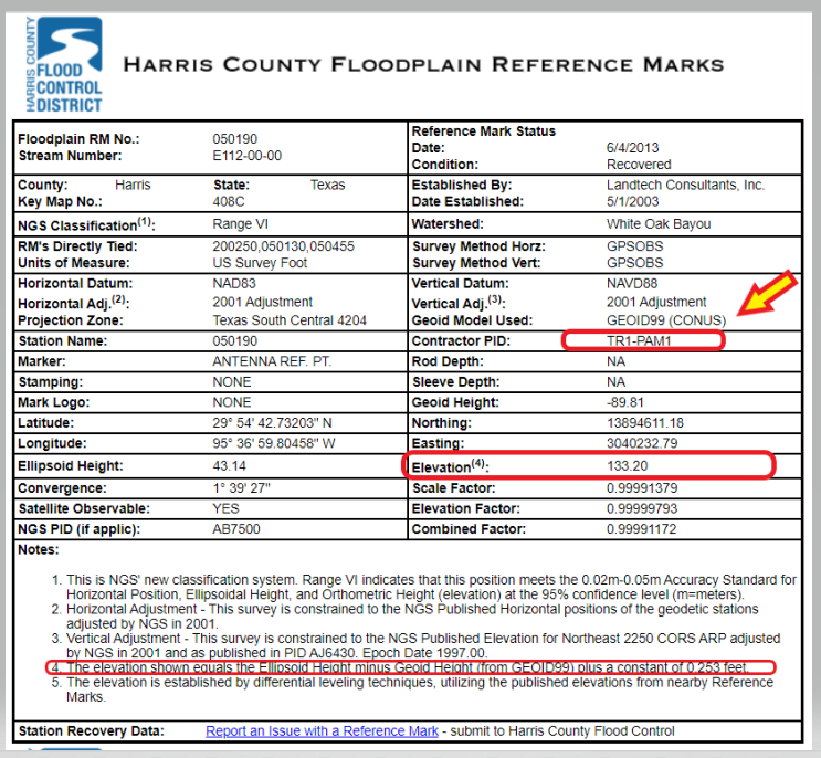
Clicking on the datasheets link, provides the information about the floodplain reference mark in the Harris County Flood Control District’s system (see the box titled “Harris County Floodplain Reference Mark Datasheet”).
It should be noted that the GNSS-derived orthometric heights were based on GEOID99 and the official hybrid geoid model published by NGS today is GEOID18. A GNSS-derived orthometric height computed using NGS’ webtool OPUS will use GEOID18 not GEOID99. The difference between GEOID99 and GEOID18 at this location is approximately 0.45 feet (0.138 meters). Users must ensure that they are using heights that are consistent with the BFE on the FIRM. The new NAPGD2022 will help to reduce issues associated with effects due to changes in geoid models.
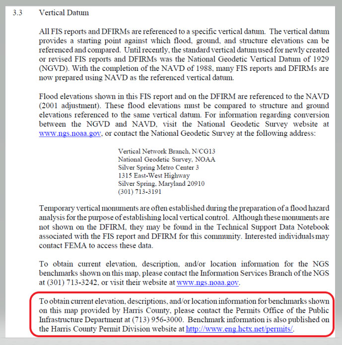
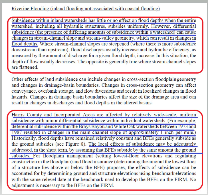
Page 113 from the November 15, 2019 Flood Insurance Study 48201CV001G addresses the issues associated with riverine flood in the region. (See the box titled “Page 113 from November 15, 2019 Flood Insurance Study 48201CV001G.”) The highlighted sections basically state that subsidence within inland watersheds has little or no effect on flood depths when the entire watershed subsides at the same rate. However, it also states that differential subsidence can cause changes in flood depths. The report goes on to say that the “Harris County and Incorporated Areas are affected by wide-scale, uniform subsidence with minor differential subsidence within individual watersheds.” It also states that “The local effects of subsidence may be adequately addressed, in the short term, by assuming that BFEs subside by the same amount the ground subsides.” The Houston-Galveston, Texas, region is a very complicated area due to the differential subsidence and numerous individual watersheds.
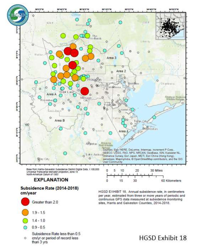
That said, let’s look some of the latest subsidence data in the region. The Harris-Galveston Subsidence District’s 2018 Annual Groundwater Report By Robert Thompson, William M. Chrismer, and Christina Petersen, PhD, P.E. provide some of the latest estimates of subsidence in the region. The box titled “HGSD Exhibit 18” depicts the locations of the GNSS sites used in the study. The plot provides the average compaction in centimeters over the past five years. The values range from 0.0 cm/year to greater than 2.5 cm/year.
HGSD Exhibit 18. This map shows the locations of the GPS sites throughout the area. The colored dots represent the average compaction over the past five years for each site, in centimeters. They range from 0.0 cm/year to greater than 2.5 cm/year. (Image: Harris-Galveston Subsidence District)
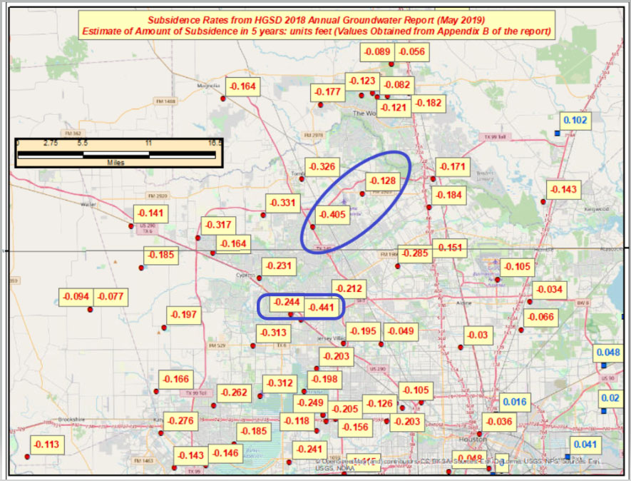
I used the information from Appendix B provided in the report to generate a few plots that show the estimate of subsidence in feet over 5 years. I’ve highlighted some marks that have large relative height changes. (Note: The units of the previous figure are centimeters; the units of the next several plots are feet.)
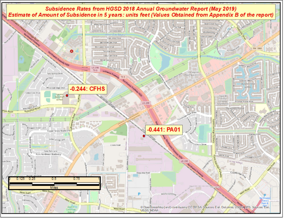
The relative height change between the two marks PA01 and CFHS, which are about 1.5 kilometers (approximately 1 mile) apart, is 0.197 feet in only 5 years. (See the box titled “Estimate of Amount of Subsidence in 5 Years at Pam 1– Units Feet.”)
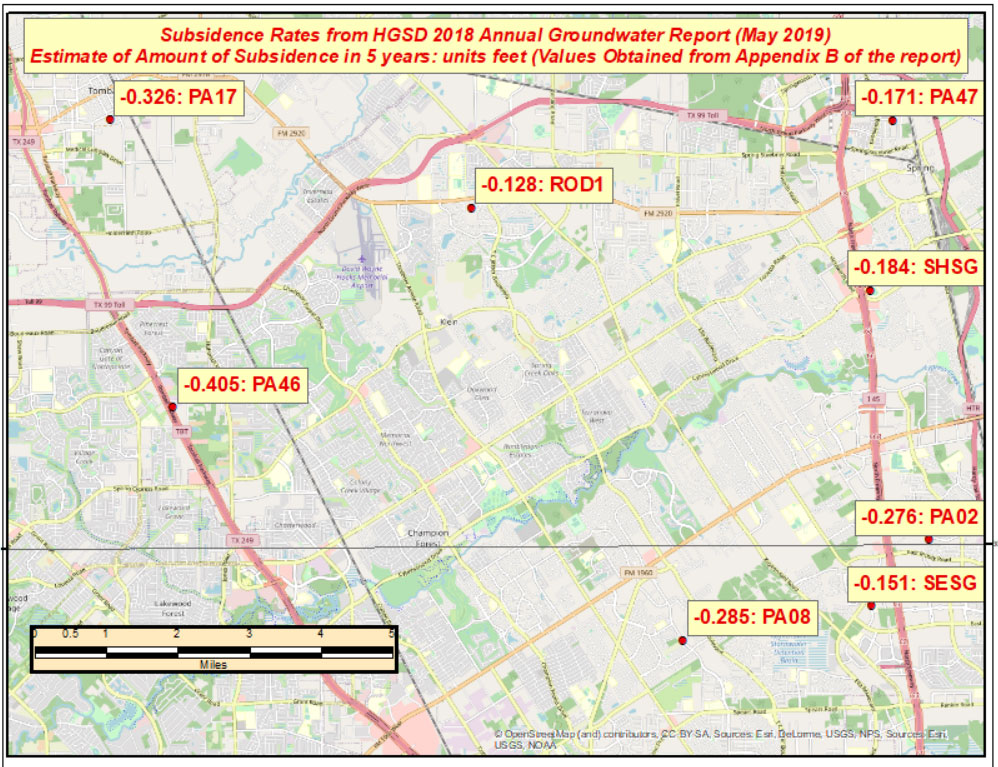
The estimated relative height change between mark PA46 and ROD1, which are about 8 kilometers (approximately 5 miles) apart, is 0.277 feet in five years. (See the box titled “Estimate of Amount of Subsidence in 5 Years at Pam 46 – Units: Feet.”)
The effect of these large relative differences may not have any effect on the BFE on a particular watershed. These subsidence estimates are at a specific mark so they only provide information at a particular location. The new NAPGD2022 along with NGS’s webtools will enable users to economically obtain current, accurate heights in the entire region. Leveraging the capabilities of the new NSRS will help facilitate the implementation of FEMA’s goal of assessing the need to revise and update all floodplain areas and flood risk zones identified once during each five-year period.
This column highlighted the potential effects of subsidence on published heights in the Houston, Texas, region, which implies that most of the published heights based on older surveys in the region are not current or accurate.
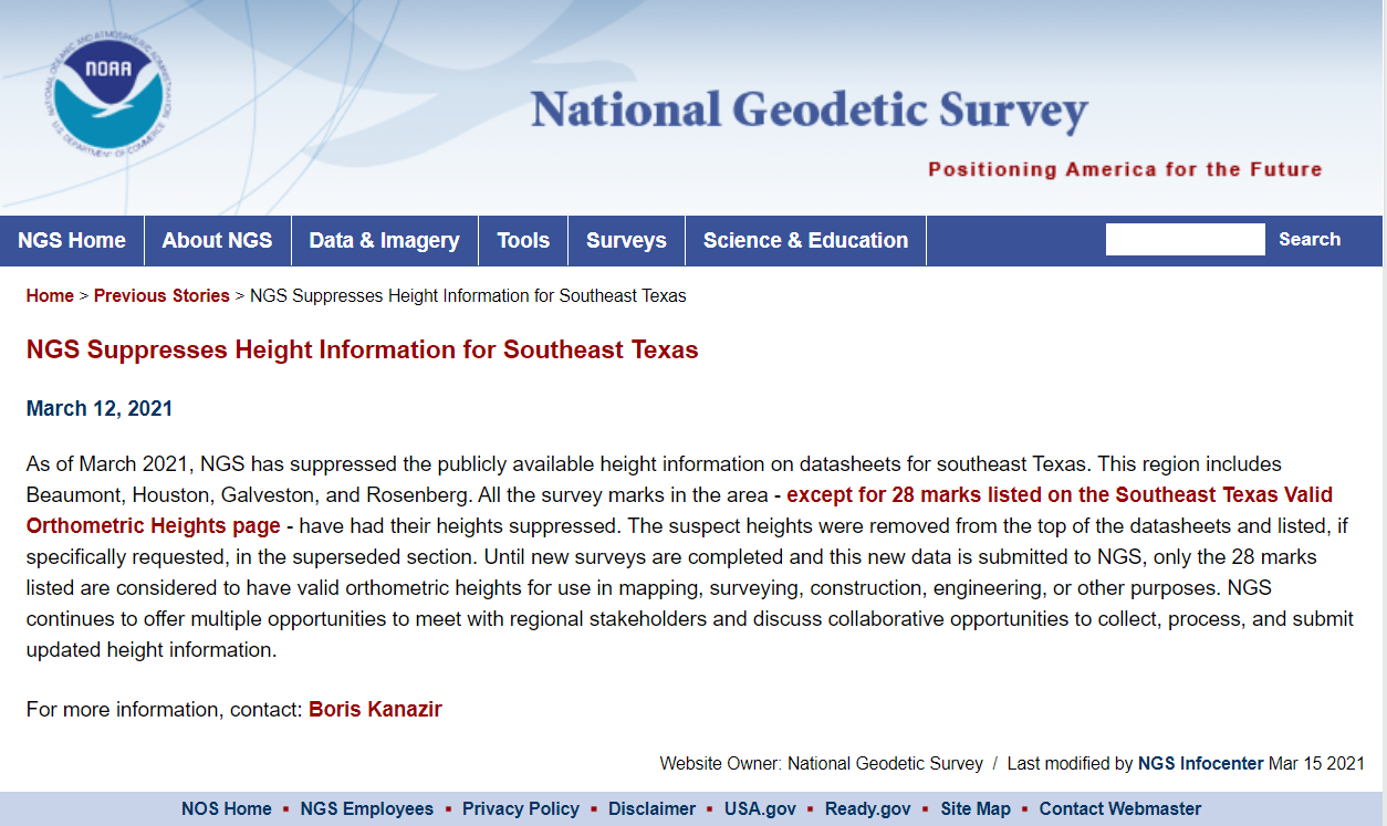
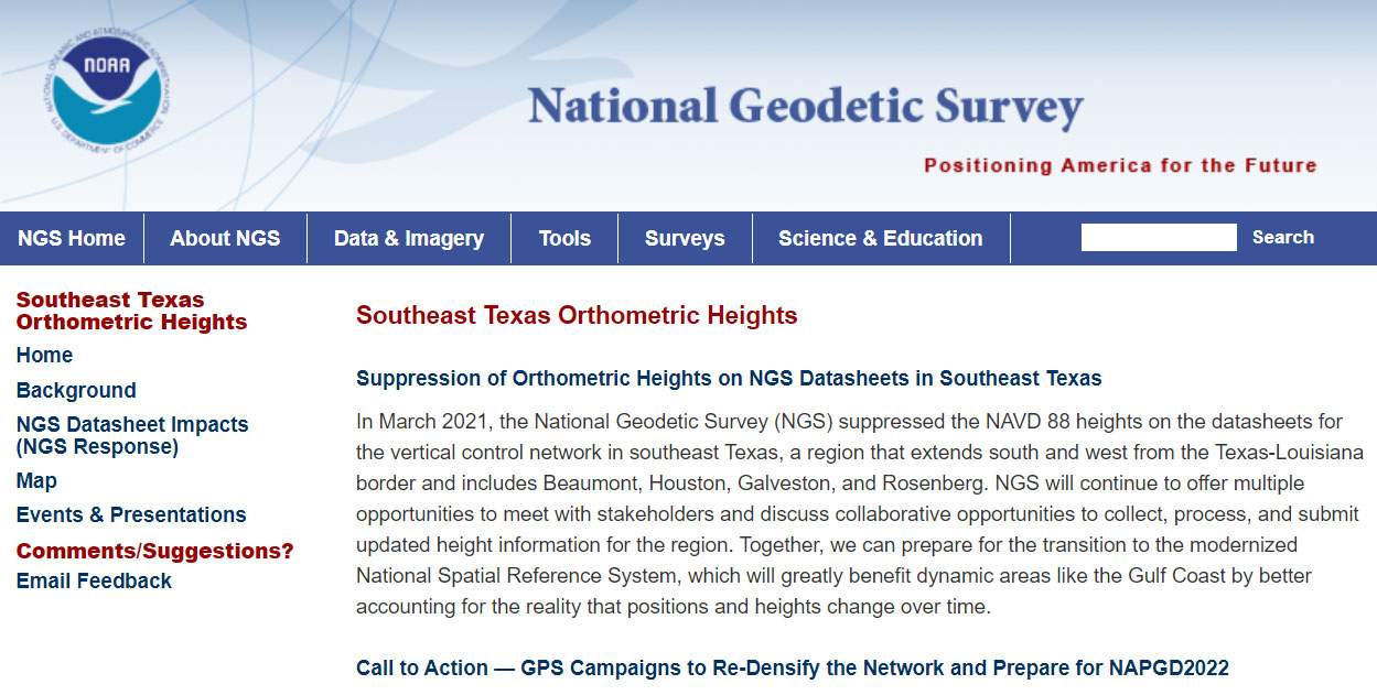
According to the announcement, only 28 marks will have publicly available orthometric heights on NGS datasheets in Southeast Texas. This NOAA website provides more information. See the box titled “NGS Southeast Texas Orthometric Heights.”
I would encourage everyone to check out the website to obtain a better understanding of what this suppression of published heights means to their operations. Future newsletters will address the suppression of the orthometric heights in Southeast Texas, and how users can help densify the network and prepare for the new, modernized NAPGD2022. Again, a benefit of the new modernized NSRS will facilitate the establishment of consistent, accurate NAPGD2022 GNSS-derived orthometric heights.
Lastly, NGS is convening the 2021 Geospatial Summit on May 4 and 5. The 2021 Geospatial Summit will provide updated information about the planned modernization of the National Spatial Reference System (NSRS). Register here.
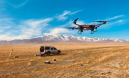
Unmanned aerial vehicles (UAVs) are something of a Swiss Army knife for the surveying and mapping communities. Commercial applications continue to grow, with UAVS — known as drones in the vernacular — gathering data and observations for agriculture, mining, utility inspections, natural resources, historical preservation, security, and many more applications.
UAVs perform high-risk tasks that keep workers out of harm’s way. They fly in places and situations difficult or impossible for aircraft to reach. They collect high-resolution imagery across the spectrum, accompanied by exact positioning and location data. They detect and help preserve the past in rich detail.
A study by Polaris Market Research predicts the UAV market will reach $15.62 billion By 2026, spurred not only by new use cases, but through miniaturization and improvement of components. Payload components that continue to improve include GNSS receivers, inertial measurement units, micro-electromechanical components, cameras of all types (RGB, thermal, hyperspectral and high-resolution video) and lidar. (For more on lidar with UAVs, see Diving into UAV lidar surveys.)
In these pages, we share a variety of case studies from companies taking part in the UAV revolution. In many of these use cases, companies saved considerable money using UAVs rather than more traditional surveying methods. In others, UAVs are helping to keep people safe.
In all cases, using UAVs provides a wealth of data that offer new insights, no matter the application.
The West Virginia Department of Transportation (WVDOT) turned to UAVs to save time and money. Incorporating drones has saved WVDOT more than $340,000 in a single month.
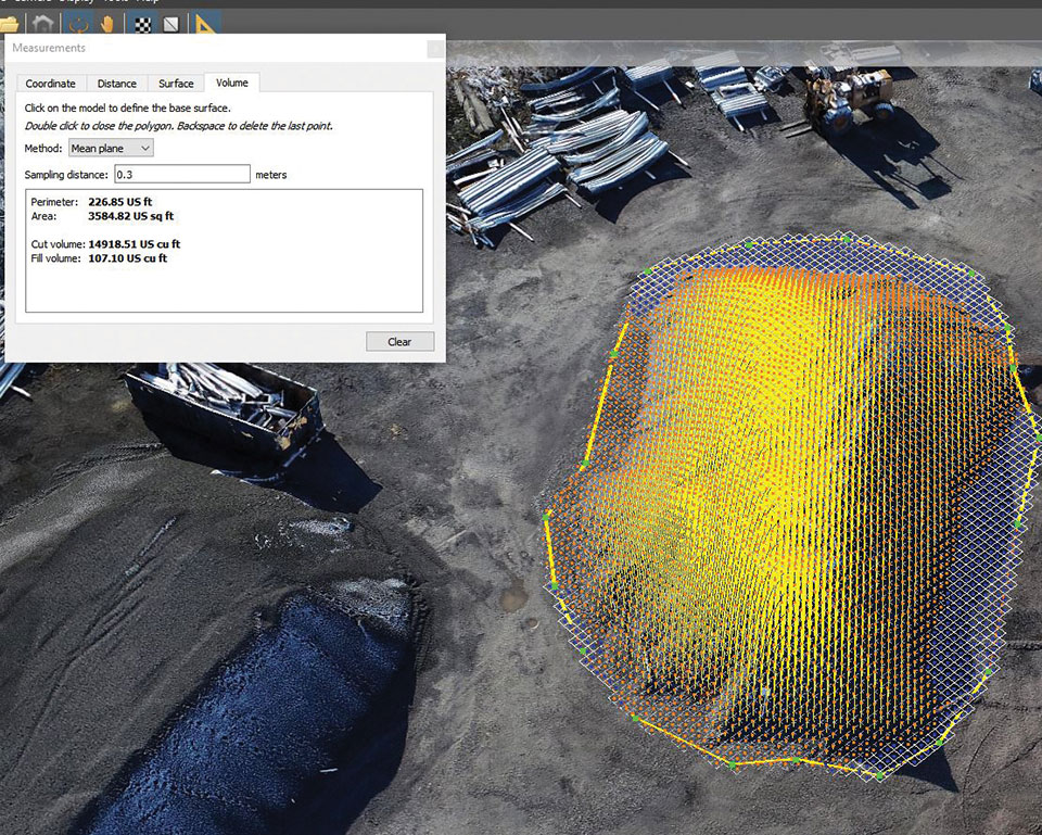
In 2017, WVDOT began formally looking into launching a drone program. WVDOT concluded that drones could be ideal for stockpile surveys — using them had the potential to speed up the process, reduce risk, and increase accuracy.
Jesse Bennett, statewide survey unit leader at WVDOT, flew several test missions to validate the use case. He quickly realized drones had huge potential to transform this time-consuming and risky task.
The agency began with a team of nine Federal Aviation Administration-certified drone pilots and 12 drones. WVDOT also began using Skyward’s Drone Management Platform to manage their flights, pilots and equipment. Skyward offered a single, digital platform to coordinate complex missions and obtain airspace permissions.
“I saw the need for something like Skyward from the very beginning, when I was the first and only pilot,” Bennett said. “I was manually making entries in flight logs and maintenance logs, and I was using about seven or eight different apps and websites just to plan and fly a mission.”
Using Skyward as a single place to keep track of every aspect of the drone program enabled Bennett to quickly resolve an investigation after someone mistakenly assumed he didn’t have authorization to fly in an area and reported him to the FAA.The software helped him demonstrate that crews were obeying FAA regulations and WVDOT’s own rules.
Starting in spring 2019, WVDOT began deploying drone crews for stockpile inspections at scale. WVDOT has 177 sites across the state that contain stockpiled materials. Each year, the stockpiles must be physically surveyed to calculate the volume of material. From 42 surveyors laboring for 15 workdays, the same workload took seven UAS pilots only nine workdays to complete the project.
Positioning company u‑blox has acquired full ownership of Sapcorda Services GmbH, a joint venture formed by u‑blox, Bosch, Geo++ and Mitsubishi Electric in 2017.
Sapcorda — SAfe and Precise CORrection DAta — provides advanced GNSS augmentation services for the high-precision GNSS mass market. The joint venture was formed by the four companies to bring scalable, affordable and high-quality GNSS positioning solutions to industrial, automotive and consumer applications.
Relevant industrial applications include autonomous vehicles, such as unmanned aerial vehicles (UAV) and unmanned ground vehicles (UGV), machine automation, surveying, monitoring and other advanced navigation applications.
Within the automotive sector, applications include automated driving and advanced driver-assistance systems (ADAS), lane-accurate navigation, telematics and vehicle-to-everything (V2X) communication.
Sapcorda Services GmbH is a GNSS service provider focusing on the emerging high-precision GNSS mass markets. The company has designed its technology and service offerings to serve high-volume automotive, industrial and consumer markets.
Sapcorda developed its advanced SAPA service based on open formats, and has specifically tailored it for industrial and automotive markets. It uses real-time kinematic (RTK) and precise point positioning (PPP).
Launched in January 2020 in the U.S. and Europe, SAPA Services have been expanded to full coverage of the contiguous U.S. and 32 countries in Europe. Distribution of the service via an additional geostationary satellite L-band signal also has been announced.
“We appreciate the support and cooperation of all the joint venture shareholders. As a part of u‑blox, I see enormous potential for our technology,” said Botho Graf zu Eulenburg, CEO of Sapcorda.
The acquisition of Sapcorda expands u‑blox’s suite of location services complementing its existing data services, including its assistance data and communication service offerings. Sapcorda has focused on establishing a platform from which to bring GNSS augmentation services to the mass market by delivering on robustness, reliability and end-to-end security as it relates to performance.
Full ownership of Sapcorda will also enable u‑blox to serve customers more efficiently, the company said, by streamlining certain processes, including reducing implementation time to market and simplifying the integration process for customers.
“The acquisition of Sapcorda reinforces our position as a leader driving innovation in the most advanced areas of GNSS positioning technology,” said Thomas Seiler, CEO of u‑blox. “It represents another step forward in the execution of our strategy, which is to deliver value to our customers by means of a comprehensive ‘silicon-to-cloud’ set of solutions and offerings.”
Sapcorda operates in Europe and in the U.S. with offices in Berlin and Hanover in Germany and in Scottsdale, Arizona, in the U.S.
The European GNSS Agency (GSA), with the European Commission, has published an information note on the Galileo High Accuracy Service (HAS). The 16-page document provides an overview of the main characteristics of the service, information on features such as service levels, target performance, an implementation roadmap, and an overview of the target markets for the service.
Target markets for Galileo HAS include geomatics, precision agriculture, consumer solutions and the space sector.
The market for high-accuracy positioning is dynamic, driven by various factors, including
emerging applications such as autonomous vehicles and drones;
technological advances such as dual-frequency chipsets for the mass-market; and
the market situation, with cheap or free-of-charge augmentation services available in some countries.
These factors are resulting in the democratization of high accuracy, which is becoming a more widespread commodity, rather than the exclusive domain of professional applications.
With the Galileo HAS, Galileo will pioneer a worldwide, free high-accuracy positioning service aimed at applications that require higher performance than that offered by the Galileo Open Service.
Benefitting several markets
Target markets for the HAS include geomatics, agriculture or consumer solutions. Transport is also a major potential target market, with possible applications in aviation, road, rail and maritime and inland waterways.
In these markets, the HAS will provide high-accuracy precise point positioning corrections for Galileo and GPS free of charge, in the Galileo E6-B data component and by terrestrial means, to achieve real-time improved user positioning performances, with a positioning error of less than two decimetres in nominal conditions.
“With its High Accuracy Service, Galileo will be the first satellite constellation able to provide a high-accuracy precise point positioning service globally, directly through the Signal in Space,” said GSA Executive Director Rodrigo da Costa. “This will be another key differentiator of the Galileo system, giving it a competitive advantage over other systems and allowing it to foster innovation in both consolidated and emerging markets.”
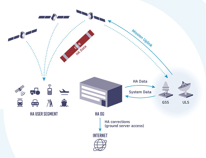
Galileo HAS high-level architecture. (Image: GSA)
HAS Initial Service
HAS Phase 1 will cover the provision of an initial Galileo HAS resulting from the implementation of a high-accuracy data-generation system that processes Galileo data only.
Phase 2 will see full provision of the Galileo HAS, meeting its target performance of 20-cm worldwide positioning accuracy after 2024.
Through the HAS, Galileo will offer a unique service with the transmission of corrections directly via Galileo satellites, allowing free high-accuracy positioning globally, for everyone.