CP Aeronautics offers American-built combat-proven unmanned aerial systems for defense, homeland security and civil applications
CP Technologies has launched a new division, CP Aeronautics, to provide integrated turn-key solutions based on unmanned aerial systems (UAS) platforms, payloads, data links, ground control stations (GCS) and communications for defense and civil applications.
Designed as leading-edge UAS-based solutions, CP Aeronautics’ systems offer operationally proven solutions for intelligence, surveillance and reconnaissance (ISR) systems requirements. CP Aeronautics’ broad product portfolio has demonstrated excellent performance and operability in demanding environments, the company stated in a press release. Backed by continuous research and development, these systems are built on three decades of technological and operational experience.
“Through our in-house capability as a UAS manufacturer and integrator with specialist subsidiaries and technology partners, we offer a complete range of subsystems including air vehicles, inertial navigation and avionics, electro-optical payloads (EO), communications, propulsion systems, launch and retrieval systems, command and control units,” said Brad Pilsl, vice president of business development at CP Aeronautics. “We also offer high-end training solutions for our partners and customers.”
CP Aeronautics will support government and commercial customers with the entire infrastructure necessary for development, production, integration, flight-testing, certification and operational support of UAS throughout their service.
The combat-proven operational systems include:
Orbiter 2 Small-UAS (SUAS)
Orbiter 3 Small Tactical UAS (STUAS)
Orbiter 4 Small Tactical UAS (STUAS)
Aerostar Tactical UAS (TUAS)
Dominator XP (MALE UAS)
Pegasus 120 high-performance multi-mission vertical takeoff and landing (VTOL) UAS
On a test track in Sweden, a truck successfully merged between two cars driving alongside it in a fully automated maneuver. The live demonstration took place at the AstaZero test site near Borås, Sweden, on Nov. 21, 2019, showing automotive industry experts how well the automated merging solution performed.
The Fraunhofer Institute for Integrated Circuits IIS and project partners RISE, Scania, Waysure, Ceit-IK4, Baselabs and Commsignia are taking part in an EU-funded project PRoPART, which stands for Precise and Robust Positioning for Automated Road Transports.
Vehicles on the road already perform certain steps on behalf of the driver, such as parking. Together with its project partners, the Fraunhofer IIS has developed a precise and robust position determination system for use in autonomous trucks as part of PRoPART.
Autonomous driving is about interactions among vehicle systems, connecting vehicles and equipping them with precise and robust navigation solutions. The challenge is to ensure that different automated driving systems deliver precise and reliable positioning information.
Using GOOSE technology
With its GOOSE GNSS receivers, Fraunhofer IIS provides highly accurate and reliable positioning to the PRoPART project. The GOOSE can bridge signal interruptions for short periods of time, potentially obviating the need for the driver to intervene at all.
In conjunction with GNSS, developers are using a combination of sensors such as radar and cameras in the vehicle. Supplemented by reference stations along the route, the combination of GNSS and sensor data enables highly available position solutions up to the decimeter range.
“This is a key step on the road to autonomous driving,” explained group manager for precise GNSS receivers Matthias Overbeck, Fraunhofer IIS. “It’s about ensuring the merging maneuver is precise and avoiding accidents — something we can achieve only with highly accurate and reliable positioning technology.”
GOOSE platform. (Photo: Fraunhofer IIS)
Spoofing protection
These days, a variety of electronic systems for providing satellite navigation signals are available and are often used to generate fake positions for gaming apps on smartphones. Such systems could disrupt satellite receivers while remaining undetected.
GOOSE makes use of the Galileo Open Service Navigation Message Authentication (OS-NMA), which is not officially available until 2020. OS-NMA transmits encrypted keys on the Galileo satellite signals that make it extremely difficult to fake a position, thus ensuring that reliable positioning information can be provided to vehicles in the future.
Vexcel Imaging, a provider of aerial imagery data, large-format aerial cameras and photogrammetry software, has signed a definitive agreement to acquire the imagery sourcing group from Verisk’s Geomni business.
The acquisition will combine Geomni’s imagery surveying and content-related teams and assets into Vexcel. Verisk, a data analytics provider, will be a minority owner in Vexcel with full access to all aerial imagery libraries.
The combination of Geomni’s fleet of fixed-wing aircraft and aerial operations, mapping business and oblique aerial image library together with Vexcel’s sensor business and data program will create a world-leading geospatial data library.
Geomni’s analytics team and assets will remain part of Verisk and continue to focus on world-class advanced analytics. The team will work closely with Vexcel on a strategic road map and joint projects.
“The strategic alliance between Vexcel and Verisk demonstrates both companies’ resolve to drive rapid innovation across imagery and analytics — to enter new markets, create new categories, and better serve commercial and insurance customers,” said Jeffrey C. Taylor, president of Geomni. “Partnering with Vexcel is a huge leap forward in the services we can provide customers.”
Vexcel Imaging was founded in 1992. The company’s successful line of UltraCam systems was launched with the first UltraCam in 2003. Vexcel is headquartered in Boulder, Colorado; operates an office in Graz, Austria; and will now have teams and operational hubs strategically located throughout the United States and in Spain.
“Our alliance with Vexcel benefits our customers through a unified, robust, and rapidly expanding global aerial imagery library that will deepen their understanding of ground truth,” said Mark Anquillare, chief operating officer of Verisk. “The combination of Verisk’s and Vexcel’s data will provide tremendous coverage for customers and help drive Verisk’s proven ability to innovate advanced analytic solutions.”
“By combining forces with Verisk, we’re making a progressive move to accelerate innovation within the geospatial data industry,” said Erik Jorgensen, chairman and CEO of Vexcel Imaging. “Vexcel and Verisk share tremendous synergies, and we look forward to bringing the definitive imagery and geospatial data library to the market — unmatched in its size, quality and breadth.”
Vexcel maintains a strong partnership with the Geospatial Intelligence Center (GIC), an insurance industry consortium spearheaded by the National Insurance Crime Bureau (NICB), a nonprofit organization dedicated to fighting insurance fraud and crime, and powered by Vexcel’s data program. The GIC empowers its member insurers to improve their decision making and risk management by leveraging aerial imagery and data in visual tools and automated processes. The partnership will provide enhanced support to GIC member insurers in the form of additional flying and processing capabilities as well as access to the newly scaled and unified geospatial library and enhanced analytics.
The transaction is expected to close the first quarter of this year, subject to the completion of customary closing conditions.
Specifically, Booz Allen’s work will aid in the development and modernization of GPS systems through major programs such as Military GPS User Equipment (MGUE), GPS III and Next Generation Operational Control System (OCX).
The NIWC Pacific Positioning, Navigation, and Timing (PNT) Division is the Navy’s principal research and development center for navigation sensors and systems.
SMC is the center of technical excellence for developing, acquiring, fielding, and sustaining resilient and affordable military space systems.
With this contract, Booz Allen will continue to serve as a key mission partner for NIWC Pacific and SMC on the important endeavor of modernizing PNT systems for U.S. and Allied warfighters.
To execute this highly complex scope of work, Booz Allen will provide a range of essential services, including system definition, requirements synchronization, capability improvement, cybersecurity engineering, platform integration and testing, and acquisition program management.
“Booz Allen’s robust track record of work in both systems engineering and cybersecurity continues to inspire trust from our clients,” said Vice President Brian Zimmermann. “Our deep bench of leaders and technical experts reassures our clients that no project is too big or too complex. It’s our privilege to help the Navy and Air Force modernize GPS systems that are so vital to the security of our nation.”
Read more about Booz Allen’s work with PNT systems here.
Staff Sgt. Reag Wood of 1st Combined Arms Battalion, 5th Brigade, 1st Armored Division, illustrates how he uses an iphone to obtain a visual image of a mock with insurgent activity during a field training exercise at White Sands Missile Range, N.M. (Photo: U.S. Army/Lt. Col. Deanna Bague)
While often an underestimated component of a positioning and navigation system, a GNSS antenna is critical to a receiver’s success in acquiring all available GNSS signals while rejecting unintentional interference, jamming, multipath and spoofing. GNSS antennas come in as many flavors as receivers, to address the challenges posed by different market sectors, applications, environments and threats to signal integrity.
Each solution reflects a different balance among performance, cost, size and other variables. For example, antennas for handheld devices must be small and lightweight, while those for excavators and dozers can be much larger and heavier but must be able to operate for years while subjected to severe vibrations and harsh environmental conditions. Antennas for military and safety-critical applications must be especially impervious to jamming and spoofing.
Most applications, however, require antennas, like receivers, to have the smallest possible size, weight, power and cost (SWAP-C). Some applications, such as in the automotive market, must also take aesthetics into account.
We asked Javad GNSS, NovAtel, Trimble, Topcon and Harxon about their key markets and the challenges their antennas are designed to address. We also asked them to look back at the past three years and forward at the next three to discuss key innovations. Finally, they discuss technical challenges and industry trends.
See part 1 and part 2 of our GNSS receiver manufacturer overviews.
Javad GNSS
The GrAnt-G2T antenna. (Photo: Javad GNSS)
Key Markets. “The unmistakable lime-green Javad GNSS receivers and antennas are known to surveyors the world over, and we also support reference station, machine control, precise timing and any other market requiring high-performance / high-precision GNSS antennas,” said Javad Ashjaee, founder and CEO.
Specific Challenges. “A good GNSS receiver should bring in all wideband GNSS signals and reject all other unwanted signals,” Ashjaee said. “J-Shield, a robust filter in our antennas, blocks out-of-band interference — in particular, signals near the GNSS bands, such as the LightSquared signals — making the precious near-band spectrum available for other usages.”
Key Innovations. “To support our users in ever more challenging environments,” Ashjaee said, “such as denied environments where electronic warfare takes place, we have developed a new GrAnt-G2T antenna variant with even stronger J-Shield filtering: improved P1dB (the 1-dB compression point, > –30 dBm) and additional upper and lower out-of-band filtering.”
Harxon
The HX-CSX100. (Photo: Harxon)
Key Markets.Harxon is dedicated to designing and manufacturing high-precision GNSS antennas and solutions for industries such as surveying, UAVs and precision agriculture, said Wang Xiaohui, R&D manager.
Specific Challenges. “Harxon’s GNSS antennas primarily address issues related to the reliability of phase center, multi-constellation full-frequency coverage,” Xiaohui said, “tracing unstable satellite signals at low elevations, multipath signal interference, and how to integrate high-precision GNSS antennas and mobile communication antennas into a single design.”
Key Innovations. Over the past three years, Harxon has made “great breakthroughs” in GNSS antenna innovation, Xiaohui said. First, it greatly reduced the size and weight of choke ring antennas. As an example, Xiaohui cited the company’s mini choke ring antenna HX-CGX611A. Second, it optimized accuracy to the millimeter level and expanded to full frequency its quadrifilar helix antenna, such as with the D-Helix antenna. Third, Harxon upgraded the surveying industry to 4G communication by developing a four-in-one antenna that supports multi-constellation with full frequencies and integrates GNSS antennas, Bluetooth and 4G modules with high compatibility and outstanding performance, Xiaohui said, such as with the HX-CSX100. “For the next three years, Harxon will continue its research and investment in antenna technology breakthroughs, especially with regard to further miniaturization and improved performance.”
Technical Challenges. “The first interesting challenge is how to guarantee the performance of the antenna while miniaturizing it per our customers’ demands,” Xiaohui said. The second is reducing the size and weight of antennas with anti-multipath technology, “so as to boost the applications of high-precision positioning GNSS technology.”
Trimble
An external Trimble antenna helps the GeoXR handheld achieve survey-grade accuracy. (Photo: Trimble)
Key Markets. “Trimble’s core technologies in positioning, modeling, connectivity and data analytics enable customers to improve productivity, quality, safety and sustainability,” said Stuart Riley, vice president, GNSS Technology. “From purpose-built products to enterprise lifecycle solutions, Trimble software, hardware and services are transforming industries such as agriculture, construction, geospatial, transportation and logistics, rail, forestry, utilities and autonomous applications.”
Specific Challenges. Each application has different requirements, Riley said. “For applications that require the highest position accuracy, the stability of the phase center, multipath mitigation, and the unit-to-unit production consistency are critical,” he said. Some customers require high performance in challenging environments — such as the high vibration experienced on construction equipment — while others require smaller, lower-cost antennas and can tolerate a slight reduction in accuracy. “The antenna is typically a combination of a passive antenna element with an active low noise amplifier (LNA),” he said. “The LNA needs to be carefully designed to remain linear in the presence of in-band jamming while rejecting out-of-band signals. There are size and cost trade-off challenges to the filter roll-off at the band edge that need to be managed.”
Key Innovations. For high-precision applications, Trimble first released the Zephyr series of antennas in the late 1990s. “It provides excellent phase center stability and unit-to-unit production repeatability, and has exceptional multipath mitigation performance, which is enhanced in the geodetic version,” Riley said. Since first introducing the antenna, Trimble has added support for additional GNSS systems and RF bands (L1/E1, L2, L5/E5 and L6/E6), transitioned to a RoHS-compliant manufacturing process, improved the LNA performance, developed rugged versions for construction vehicle mounting, and produced a smaller version used in the Trimble R10, R12 and SPS986 GNSS receivers.
“More recently,” Riley said, “we developed a lower-cost high-performance antenna for the Trimble Catalyst software-defined GNSS receiver for Android phones and tablets, as well as an antenna in the Nav-900 guidance controller for agriculture that implements a metamaterial design. Looking forward, we expect to continue to innovate by providing antennas that meet the needs of the different markets we serve. Each application has unique requirements, which require us to balance the cost, performance and size to develop the appropriately optimized product. Enhancements will include novel antenna architectures, production technique improvements, and careful material selection.”
Technical Challenges. Trimble users have a wide variety of requirements, Riley said. “The challenges come in balancing the seemingly conflicting needs for performance, size, weight and cost. Because Trimble focuses on specific user segments, we can provide antenna solutions that are the best fit for the various applications. For example, an antenna in a handheld device must be small and lightweight; however, on a construction machine, durability takes precedence over size and weight.”
Topcon Positioning Group
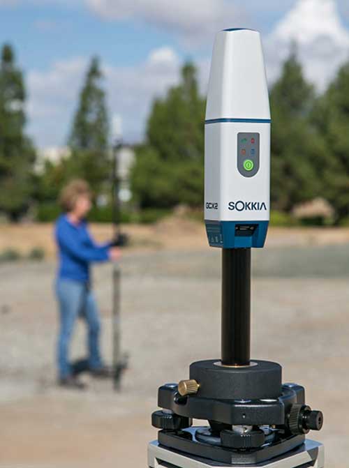
The Sokkia GCX2 receiver integrates a helical antenna. (Photo: Topcon)
Key Markets.Topcon Positioning Group is a leading designer, manufacturer and distributor of precision measurement and workflow solutions for the global construction, geospatial and agricultural markets, according to Alok Srivastava, director, product management. “By integrating high-precision measurement technology, software, services and data, Topcon has a vision to improve productivity to meet global demand for sustainable infrastructure and agriculture,” Srivastava said.
Specific Challenges. The physical challenges when designing an antenna for geomatics applications have been multipath and interference mitigation, Srivastava explained. “Topcon has an advanced research and development team that focuses solely on antenna designs. The team dedicates its efforts to providing state-of-the-art antennas for all positioning needs.”
Key Innovations. “Topcon was very early in realizing the growing needs for radio spectrum and the challenges it may bring to GNSS technology,” Srivastava said. “It has innovated and used filters to mitigate interference from Japan LTE signals for a long time.”
Topcon’s antenna team is “among the most innovative in the industry,” Srivastava said, and “has brought many unique designs of antennas over the years. The antenna is a key element of an integrated receiver in dictating the design of the whole receiver.” With the release of the Sokkia GCX2 receiver, he explained, his company introduced to the industry the integration of a helical antenna into a high-performing integrated receiver.
Its infrastructure antennas, the CR-G5 and PN-A5, are available with options including cavity filter technology. “The cavity filter has the superior ability to minimize near-band interference,” Srivastava said. Topcon’s antenna farm at the Concordia test site in Italy contains an absolute calibration robot, a large format antenna (BigAnt) for a high-quality geodetic ground station, and patented technology for controlled testing of GNSS technology in artificial obstructions.
“Vibration mitigation is the key when an antenna is mounted to a piece of machinery,” Srivastava said. “Topcon antennas are an integral component of our Quartz Lock Loop (QLL) technology for robust GNSS operation in high-vibration environments.”
Technical Challenges. The importance of antennas can be underestimated, Srivastava pointed out, especially with rapidly growing interest in GNSS technology in consumer applications. “The antenna is one of the most critical technologies when it comes to reliable and robust GNSS positioning. Designers and manufacturers of antenna technology with years of experience understand the seriousness of this task, and are fully equipped to deliver results without compromising quality and performance.”
NovAtel
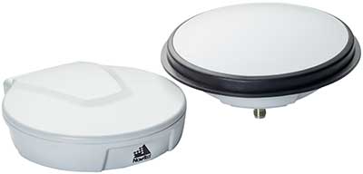
The VEXXIS family of GNSS antennas. (Photo: NovAtel)
Key Markets. Key antenna markets for Hexagon’s Autonomy & Positioning division are split into three areas, according to Dean Foster, director of hardware engineering. His area includes the company’s anti-jamming antenna technology (GAJT) and robust SWAP-C antennas. The other two are precision and SMART antennas for agriculture, mining, survey and autonomous vehicles (Vexxis, SMART7, and GNSS 1500), and reference GNSS antennas (GNSS750 and ANT-C2GA).
Specific Challenges.NovAtel’s antennas address three main challenges. First, jamming and interference, whether intentional or unintentional, are becoming increasingly commonplace and seriously impact GNSS reception. “These issues are addressed by our GAJT product line of high-precision anti-jamming antennas, which can mitigate multiple jammers simultaneously,” Foster said. Second, “the stability and precision of the antenna’s phase center is critical to deliver robust and precise GNSS position even in challenging environments, which is addressed by our Vexxis GNSS-800 antennas.” Finally, more frequent use of GNSS in environments with reflection issues is making multipath rejection critical. “The entire line of NovAtel antennas, including Vexxis, SMART and GAJT, ensures use of the most direct signals.”
Key Innovations. Driverless vehicles require sub-meter-level positioning for lane-level resolution. “Multi-constellation/multi-frequency GNSS with protection limits and correction services are necessary to move forward safely,” Foster said. “This technology does not work with the smallest size, single-frequency, narrow-band antennas that cars currently utilize, so we’re building on our deep experience and knowledge to develop production-grade automotive antenna technologies.” An emerging requirement is reducing size, weight, power and cost (SWAP-C). “In the defense market, we first offered jamming and interference mitigation with the GAJT-710, which progressed to the GAJT-AE, and most recently we launched the GAJT-410.”
Technical Challenges. All markets want the smallest, most robust and cost-effective antenna to meet their needs, Foster said, adding that NovAtel is helping customers work through how to select, place and integrate antennas into their platforms to address real-world problems.
The prevalence of intentional and unintentional GNSS interference has sparked quick evolution in antenna technology, including the emergence of breakthrough technology in 2019 and new advancements in development, said Imtiaz Bahadur, product line manager.
Specifically, the drive to advance antenna technology is due to “an increased demand for broader coverage, stringent industry compliance, and a need for robust capabilities.”
Key Innovations. Among recent innovations in antenna technology, Bahadur cited GPS antennas with support for dual-frequency multi-constellation compliance with Global Aircraft Traffic Management (GATM) mandates to enable military aircraft to operate in controlled airspace, and antennas that offer broader band coverage.
In 2019, Cobham introduced the 20-2041 Fixed Reception Pattern Array (FRPA) GPS antenna, which addresses all three of these priorities, said Darren Windust, product manager – air. The L1/L2 dual-frequency GPS antenna is certified to both ETSO-C190 and MSO-C144. “In conjunction with a certified receiver, the 20-2041 offers a single solution to comply with GATM regulations to access controlled airspace and undertake GPS precision approach and landings, in a standard 3.5-inch form factor.”
Technical Challenges. “It’s clear that moving from one GPS signal to eight signals from four constellations in support of performance-based navigation is going to be the next major disruptor because of the significantly expanded signal power and highly efficient design,” Bahadur said. The quest to make antennas smaller also continues. “Today, there are physical limitations on how far one can miniaturize the antenna while ensuring sufficient gain is received. Research and development efforts are underway to build ‘smart antenna’ concepts for the future. Moving into the next few years, robust antenna capabilities will arrive in smaller, more efficient form factors.”
In the second part of our receiver feature, top receiver manufacturers discuss what’s on the horizon for GNSS receivers: recent and upcoming innovations, combating spoofing and jamming, fusing GNSS with other sensors, and the impact of increasing accuracy both for professional surveyors and consumers.
In January, we featured responses from NovAtel, Trimble, Unicore, Topcon, Hemisphere GNSS, CNC Navigation and Septentrio to questions about their recent and upcoming innovations in the design and manufacturing of GNSS receivers. We continue in this issue with responses to the same questions from Javad GNSS, Swift Navigation, Eos Positioning Systems, Tersus GNSS, TeleOrbit, Allystar Technology and NTLab.
All GNSS receiver manufacturers agree that spoofing and intentional and unintentional jamming are serious challenges. Their approaches to dealing with these challenges differ, however, as they rely on different combinations of technologies on both their receivers (such as monitoring cycle slips and using analog-to-digital converters, correlators and notch filters) and their antennas (such as using array antennas), as well as the new Galileo authentication service.
Photo: Tersus GNSS
Many receiver manufacturers now routinely use optical, inertial and other sensors — which continue to drop in price and increase in performance — to supplement GNSS signals where they are degraded or denied, especially in the automotive market.
Carrier phase positioning and correction services are increasingly improving the accuracy of survey stations and reducing their price. Meanwhile, submeter accuracy is spreading beyond surveying to other industries. Performance in challenging conditions also continues to improve, thanks largely to the increase in the number of GNSS constellations, available satellites and frequencies. (For a review of recent developments in antennas, see our companion article here.)
On the consumer side, the introduction of multi-frequency GNSS receiver chips, the increased use of correction services, and, in a few countries, the deployment of thousands of additional base stations will continue to increase the location accuracy of cell phones and other consumer devices, enabling new applications. However, in these devices size and cost limitations make antenna performance particularly challenging. (See Part 1 here.)
Javad GNSS
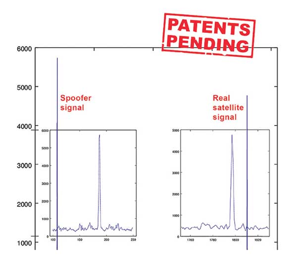
Jamming and Spoofing. “We protect you against jammers and spoofers like no one else can,” said Javad Ashjaee, founder and CEO of Javad GNSS. “We use multiple techniques to detect spoofers, the most important being the use of digital signal processing to detect more than one peak. First, with 864 channels and about 130,000 Quick Acquisition Channels in our Triumph chip, we have resources to assign more than one channel to each satellite to find all signals that are transmitted with that GNSS PRN code. If we detect more than one reasonable and consistent correlation peak for any PRN code, we know that we are being spoofed and can then identify the spoofer signals and ignore the wrong peak.”
An example of two peaks. (Chart: Javad GNSS)
Ashjaee described additional techniques:
The J-Shield filter blocks out-of-band interference.
Sixteen 255th-order FIR anti-jam digital filters protect against static in-band interference, and 16 adaptive 80th-order digital filters protect against dynamic interference.
Javad products measure the level of interference as a percentage of in-band noise above normal.
The Triumph chip has a powerful spectrum analyzer. Each spectrum shows the power and the shape of the interfering signals and jammers. This is more powerful and more efficient than using a commercial spectrum analyzer to evaluate the environment.
The chip also keeps a record of Automatic Gain Control, which is another indicator of external signals. A change in AGC can indicate interference.
Deviation of SNR from the expected value is another important indicator of interference.
“Usually there are over 100 signals available at any given time, and we need only four good signals to compute position. It is extremely unlikely that we can be spoofed without our knowledge.” Ashjaee concluded. “We will immediately recognize and take corrective actions.”
Jamming and spoofing protection is available on all Javad GNSS receivers and OEM boards. Read more about Javad GNSS’s jamming and spoofing protection in the December 2019 issue.
Sensor Fusion. “To support users in environments where GNSS RTK solutions are difficult or impossible to obtain,” Ashjaee said, “Javad GNSS has invented the J-Mate, which is a remotely controlled robotic EDM device and digital camera. GNSS RTK and optical can be seamlessly integrated using the J-Mate as the seventh RTK engine. Just set up a Triumph-3 on top of a J-Mate and a Triumph LS on top of a zebra rod, making the former pair the RTK base station and the latter pair the RTK rover.” Read more about Javad GNSS’s RTK and Optical United solution in the November 2019 issue.
Swift Navigation
Jamming and Spoofing. “Receivers have become more robust to intentional jamming by mimicking the jammers’ behavior to cancel it,” said Alex Pun, staff product manager for Swift. “Nevertheless, advanced jamming and spoofing mitigation often imply array antennas. A real evolution lies in considering these threats only in terms of the availability of the GNSS sensor, now part of a complete multi-sensor positioning engine such as Starling.”
Sensor Fusion. IMUs, visual sensors and GNSS will aid each other in different types of environments and scenarios, explained Pun. “Sensors are becoming more affordable, and their performance increases with each new generation. Sensor fusion will be the glue that will bind them to provide a precise positioning solution.”
Surveying. The combined use of carrier-phase positioning and correction services, such as Swift’s Skylark, will greatly improve accuracy and reduce the cost of survey stations, because they make their accuracy less dependent on the intrinsic performance of the receiver and the antenna, Pun said. “A global service eliminates the need for an individual base station.”
Consumer Devices. “The introduction of dual-frequency GNSS receivers from chip manufacturers will help improve positioning in cell phones and other consumer devices,” Pun said. “These chips, coupled with a widely available correction service such as Skylark, will greatly improve their performance accuracy to sub-meter levels.”
Other Challenges. Performance stability of the antenna and its characterization will become the main challenge to exploiting the new GNSS ASICs (application-specific integrated circuits) and correction services at their highest level of performance, Pun said. “A positioning engine can exploit this information to accelerate the convergence to the high-accuracy solution, and then improve its availability.”
Eos Positioning Systems
A surveyor uses the Arrow Gold receiver to map assets in Terrebonne, Quebec, Canada. (Photo: Eos Positioning)
“The past three years have seen considerable innovations and trends in the GNSS industry,” said Jean-Yves Lauture, CTO of Eos Positioning. “Receivers are becoming increasingly affordable and the adoption of higher-accuracy (submeter, centimeter) positioning by other industries, outside of conventional surveying, is growing. Considering the now four usable GNSS constellations and the aggressive launches of Galileo and BeiDou satellites, the number of available satellites and the list of frequencies they use has considerably increased.
“Although accuracy itself is not really improving, performance is — particularly in tougher conditions. It’s not uncommon for customers to use 30 to 35 satellites out of more than 40 in view using an Arrow Series GNSS receiver. The numbers are even higher in the Pacific regions, thanks to geostationary BeiDou satellites. This is, by far, more than double the number of satellites available with just GPS and GLONASS.”
Consumer Devices. “It will be challenging for smartphones and consumer devices to achieve survey-grade accuracy in the next few years. They face certain limitations. For instance, there is a cost and physical size associated with using a high-end GNSS antenna with a minimum of ground plane to achieve these levels of accuracy.
The Arrow Gold RTK GNSS receiver. (Photo: Eos Positioning)
“Also, it is unlikely that the manufacturers of consumer devices will invest in developing the advanced algorithms needed for a high level of constant accuracy and performance. In order to fit into a smartphone, consumer-grade GNSS chipset manufacturers must drop the use of many available signals and frequencies to keep both size and power consumption to a minimum.”
Allystar Technology
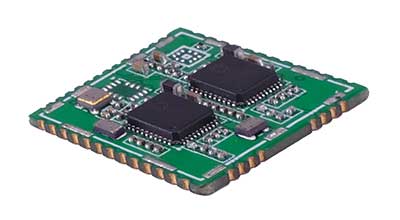
Photo: Allystar
Jamming and Spoofing. The GNSS chip in Allystar’s TAU1301 module supports eight adaptive notch filters to reduce the effects of GNSS jamming, explained Shi-Xian Yang, senior principal engineer in the company’s Baseband Algorithm Department. “It significantly improves the performance of GNSS tracking measurements, even in the presence of strong and fast-varying jamming signals.”
Sensor Fusion. The TAU1310 integrates a six-axis micro-electromechanical system (MEMS) gyro, which makes its affordable for the mass market, Yang said.
The Lenovo Z6. (Photo: Lenovo)
Consumer Devices. In its Z6 smartphone, Lenovo has taken advantage of the great improvement in multipath mitigation provided by the L5 signal’s higher chip rate and the output of high quality raw data via the TAU1302’s HD8040 GNSS chipset to improve the accuracy experience in the consumer market, Yang explained. Additionally, he pointed out, cell phones and other consumer devices now enable developers to access the raw sensor data from such sensors as accelerometers and barometers to input into their fusion algorithms.
Other Challenges. In the future, the TAU1310 could also support the L6 signal for PPP-RTK application.
NTLab
NTLab anti-jamming GNSS receiver. (Photo: NTLab)
Jamming and Spoofing. The problem of jamming and spoofing worries customers, according to Konstantin Yuriev, lead GNSS engineer at NTLab. The combination of anti-jam and anti-spoofing is in greater demand because the anti-jam feature alone is becoming insufficient. Yuriev cited the European Union’s new requirements for the European Railway Traffic Management System (ERTMS), which makes anti-spoofing mandatory.
The key issue today is “the solution to the problem of reducing the size and cost of anti-jam receivers, so that they become available to consumers on the civilian market. The key technology for this will be increasing the degree of integration of the component base, first creating a chipset for solving anti-jamming and anti-spoofing tasks, and then moving on to a single-chip solution. We have created a chipset and are ready to start work on the further integration into a single chip.”
Sensor Fusion. The traditional task of integrating data from a GPS antenna and a MEMS sensor has been solved, Yuriev said, with many such solutions on the market. One task is to track the antenna’s tilt. “The antenna, GNSS receiver, and MEMS sensors should be located very closely to each other — if possible, on a single small board,” Yuriev said. “Here, again, the solution is to increase the degree of integration, up to placing the baseband processor on the same chip with the digital CMOS circuitry of the MEMS sensor.” Another application of MEMS is serving as the core of an inertial navigation system (INS), providing an auxiliary subsystem for detecting the presence of spoofing. “This is more of an algorithmic task,” Yuriev said, “because traditional coupling using recursive filters is not enough. It is necessary to ensure the independence of the INS subsystem from the GNSS solution, or their intelligent mutual cross-control.”
Surveying. A major part of the cost of a survey-grade device, Yuriev pointed out, is for additional services, know-how, and other added values. There is market demand for a business model in which device price could go down while maintaining the main values for the customer. “This could be achieved if end-users tightly cooperate with hardware manufacturers, skipping third-party integrators. Alternatively, multiple third parties could compete, keeping the cost of the software low. One of the technical solutions for this is to provide software application programming interfaces (APIs) that will allow multiple third parties to offer application-level software for the same hardware. We call it the ‘open platform’ approach. One of our products implements this strategy.”
Other Challenges. Despite some skeptics, Yuriev argued, new GNSS systems have been successful. “A good example is IRNSS (NavIC), with India’s population of 1.3 billion forming a potential market. Moreover, according to our studies, good coverage is provided not only in India’s territory. We are working on creating an economically affordable solution with support for the NavIC S-band. A new chip-scale packaged RFIC (radio-frequency integrated circuit) should minimize the size, consumption, and price of NavIC-oriented modules, while maintaining all the advantages of the S-band signal in areas close to the equator. This is our solution to the problem.”
TeleOrbit
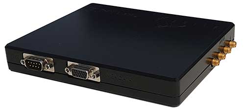
GOOSE platform. (Photo: Fraunhofer IIS)
GNSS Receiver Development Platform. The company’s GOOSE platform is a field-programmable gate array (FPGA)-based GNSS receiver, developed by Fraunhofer IIS, making it flexible in processing new or proprietary signals, according to Katrin Dietmayer, software development engineer at Fraunhofer IIS. “It comprises 60 hardware channels in real time and provides an open software interface for customer applications,” she explained.
Jamming and Spoofing. “It grants deep access to the hardware interface, down to, for example, the correlation values. Additionally, anti-jamming functions (such as notch-filter or pulse-blanker) can be added and anti-spoofing algorithms are already implemented. Thanks to the open architecture, our customers can also implement these or other algorithms.”
Sensor Fusion. Vector tracking in real time is already implemented on code base. Deep coupling with INS/IMU multi-sensor fusion — for example, with an odometer, ultra wideband or 5G — are possible and under development, Dietmayer said.
Surveying.TeleOrbit provides GNSS-RTK using RTKLIB. “The implemented Open GNSS Receiver Protocol (OGRP) is fully documented with a parsing tool using CONVBIN from RTKLIB as RINEX converter,” Dietmayer explained.
Consumer Devices. GOOSE is also used as the reference receiver in the ESA project Receiver Technologies for Future Mass Market (RT4FMM) devices. The project validates state-of-the-art dual-frequency mass-market receivers based on Broadcom BCM47755 and u-blox F9 and compares their performance against GOOSE E5AltBOC processing.
Other Challenges. GOOSE already processes the new Galileo OS-NMA (Open Service – Navigation Messages Authentication), while implementing the new Galileo High Accuracy Service (HAS) is on the roadmap. “The combination of these new features will result in a robust and reliable high-accuracy position,” Dietmayer said. “For system testing, the intermediate frequency signals can be recorded, processed and replayed with the platform.”
Tersus GNSS
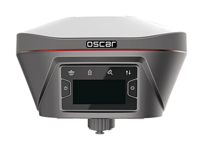
The Oscar. (Photo: Tersus GNSS)
Jamming and Spoofing. Xiaohua Wen, founder and CEO, said his company has done much research and testing on jamming and spoofing. “We already implemented a high dynamic analog-to-digital converter to overcome jamming. To mitigate spoofing, we think that internet of things (IoT) devices can leverage cloud services. Alternatively, the new Galileo authentication service may serve the same function.”
Sensor Fusion.Tersus GNSS makes an INS product, and its Oscar receiver contains an inertial measurement unit (IMU). “The sensor fusion hub is a very hot topic in the automobile industry,” Wen said. “We are quickly adapting our Oscar and INS product line for the creation of high definition maps and for indoor navigation. We think it’s still the major pain point for a crowded country such as China.”
Surveying. As has been the case in many other industries, Wen said, the widespread adoption of GNSS technology and the increase in the number of players in the field has led to a drop in prices. “Tersus’ David and Oscar models are low cost but still perform well compared with Tier 1 players for professional survey machines using our own OEM GNSS board,” he said.
Consumer Devices. The fact that a few vendors are providing dual-frequency chipsets in smartphones opens the door for consumer-grade sub-decimeter applications, Wen said. “But we think the antenna could be a big challenge for the small devices.”
Other Challenges. “Mobile carriers are building thousands of base stations,” Wen said. “For example, Softbank in Japan completed 3,300 stations this year. China Mobile just issued a bid for a phase one project for 4,400 stations. We think mobile phone innovations for the new high-accuracy application may have some impacts in the coming years. We have been actively looking at some new GIS (geographic information systems) applications based on our in-house Nuwa platform.”
My last column, December 2019, highlighted the National Geodetic Survey’s (NGS) new Geoid Monitoring Service (GeMS); and, that NGS’ will be publishing a gridded geoid model GEOID2022 that will contain two components: (1) Static Geoid model of 2022 (SGEOID2022) and (2) Dynamic Geoid model of 2022 (DGEOID2022). That’s what going to happen in 2022, but what about today? Since GEOID18 has been officially released for public use, it’s time to look at differences between the Geoid18 published value and estimated geoid values computed using information from NGS’ datasheet. This column will provide an analysis of the differences between the latest published hybrid Geoid18 values provided on NGS’ Datasheet and the computed geoid height value using the published NAD 83 (2011) ellipsoid height and NAVD 88 orthometric height. This is what a user will see if they computed differences using NGS’ datasheets published values. The question will always be asked, why is there a difference between the published Geoid18 value and the computed geoid value. This column will explain some reasons for the differences.
It’s mostly good news but there are some issues that should be highlighted. This column will highlight issues on differences due to published heights that have changed since the database pull for Geoid18.
First, it should be noted that NGS’ hybrid geoid models are different than NGS’ experimental gravimetric geoid models. My December 2018 column explains these differences.
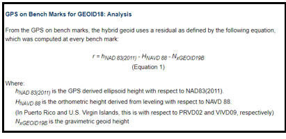
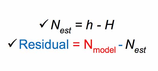
I would like to emphasize that, in my opinion, hybrid geoid models should be denoted as transformation models. Saying that, hybrid geoid models are related to “real” geoid models. Hybrid geoid model GEOID18 was computed based on NGS’ gravimetric geoid model xGeoid19b; therefore, GEOID18 is related to a gravimetric geoid model but its function is to estimate GNSS-derived orthometric heights consistent with NAVD 88 heights. As described in my previous columns, the GPS on Bench Marks (GPSBMs) data provide an estimate of the geoid height ‘N’ by differencing the ellipsoidal height ‘h’ from the orthometric height ‘H’: (N = h – H). These differences are then compared to the gravimetrically-derived geoid model. The box titled “Excerpt from Geoid18 Website Technical Details” provides a summary of the process from NGS Geoid18 web page technical details document.
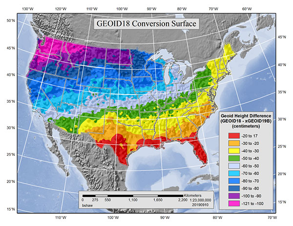
The figure in the box titled “GEOID18 Conversion Surface in cm” is the surface that represents the difference between NAVD 88 as a datum and the geopotential (geoid) surface used in the gravimetric geoid. This is the difference between the hybrid geoid and the gravimetric geoid with respect to NAD83 (GEOID18 – xGEOID19B). This surface has three essential components: a bias, a continental tilt, and local warping from the bench marks.
Hybrid Geoid Model Construction
The residuals obtained in equation 1 are contaminated with a continential tilt and bias that is estimated and removed with a simple two-dimensional planar surface. The bias-free and tilt-free residuals are ultimately used to determine a mathematical model using least squares collocation (LSC) and multiple Gaussian functions to describe the behavior seen at the bench marks. Once the relationship between the points is modeled, the model is used to generate a 1 arcminute regular grid for interpolation purposes. Figure 2 shows the final conversion surface. This surface represents the difference between NAVD 88 as a datum and the geopotential (geoid) surface used in the gravimetric geoid. This is the difference between the hybrid geoid and the gravimetric geoid with respect to NAD83 (GEOID18 – xGEOID19B). This surface has three essential components: a bias, a continental tilt, and local warping from the bench marks.
GEOID18 Conversion Surface in cm
Image: National Geodetic Survey
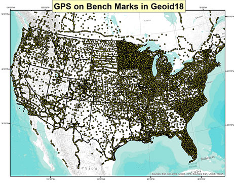
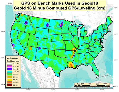
Looking at the figure in the box, the bias and tilt between the hybrid geoid model (Geoid18) and the experimental gravimetric geoid model (xGeoid19b) are fairly obvious. It’s the local warping from the bench mark data that may cause some issues to surveyors or, at least at a minimum, raise some concerned by surveyors. The box titled “Plot of the GPS on Bench Marks Involved in Geoid18” provides a plot of the GPS on Bench Marks (GPSBMs) used in the generation of Geoid18. Users can download the list of GPSBMs stations from the NGS Geoid18 website. There were 32,357 stations used to generate the model. This was an increase of approximately 6,800 stations (26%) over the hybrid geoid model Geoid12B.
Plot of the GPS on Bench Marks Involved in Geoid18
Image: National Geodetic Survey
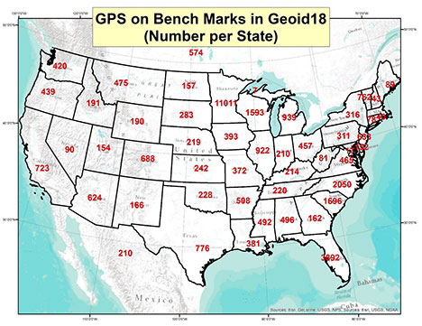
The boxes titled “Number of GPS on Bench Mark Stations by State” and “Number of GPS on Bench Mark Stations by State in Northeast U.S.” provide the number of data points per state.
Number of GPS on Bench Mark Stations by State
Image: National Geodetic Survey
Number of GPS on Bench Mark Stations by State in Northeast U.S.
Image: National Geodetic Survey
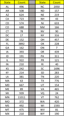
The box titled “Table of Number of Data Points per State” provides the number of stations per State in tabular form.
Table of Number of Data Points per State
Data: National Geodetic Survey
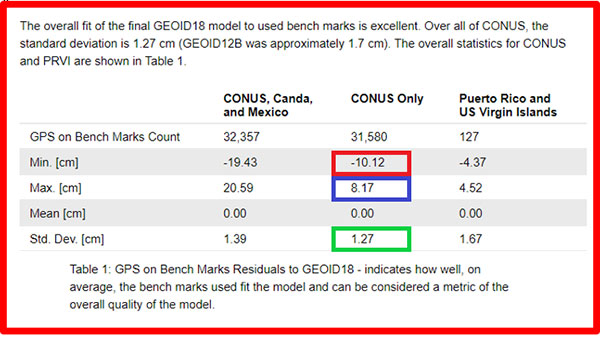
The box titled “Summary of Overall fit of Geoid18” provides a summary of the fit of residuals of Geoid18 from the NGS GEOID18 technical details document. Looking at the CONUS overall values, the standard deviation is very low 1.27 cm which is a little better than Geoid12B (1.7 cm). It should be noted that there are some large outliers (minimum value of -10.12 cm and maximum value of 8.17 cm).
For this column, the file of bench marks provided on the NGS Geoid18 web page were combined with the published ellipsoid, orthometric, and Geoid18 heights from NGS’ datasheet. The difference between the published geoid height (Geoid18) and the estimated geoid height [published NAD 83 (2011) ellipsoid height minus NAVD 88 orthometric height] was computed using the following formula:
Data: National Geodetic Survey
The box titled “Plot of Differences Based on GPS on Bench Marks Used in Geoid18” depicts these differences based on the stations used to generate Geoid18.
Plot of Differences Based on GPS on Bench Marks Used in Geoid18
Image: National Geodetic Survey
Most of the values depicted on the plot are within the +/- 2 cm which is what you’d expect because the standard deviation of the overall fit is 1.4 cm. One to two centimeters is a very reasonable difference between the modeled and computed values. The question someone may ask is, I thought the model should be good to 1.4 cm so why are there large residual values on the map? There are several reasons why some of these differences are large but each case needs to be investigated to determine why they are large. This column will address one region as an example and provide a method for others to investigate differences in their area of interest.
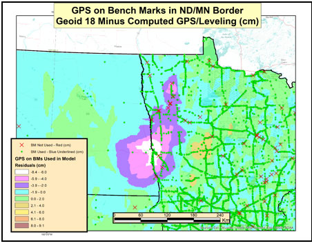
The box titled “Plot of GPS on Bench Mark Differences at the ND/MN Border” depicts a very large difference between the modeled geoid model and the estimated geoid height along the ND/MN border. As indicated in the box, the difference exceeds 6 cm.
Plot of GPS on Bench Mark Differences at the ND/MN Border
Image: National Geodetic Survey
The box titled “Plot of GPS on Bench Mark Stations in the ND/MN Border Region” depict the bench marks involved in the development of Geoid18. The green circles represent the GPSBMs stations used in the creation of Geoid18 and the red “x” denote the stations that were not used in the creation of the model. As indicated in the plot, there were a lot of GPSBMs stations in the State of Minnesota (11,011).
Plot of GPS on Bench Mark Stations in the ND/MN Border Region
Image: National Geodetic Survey
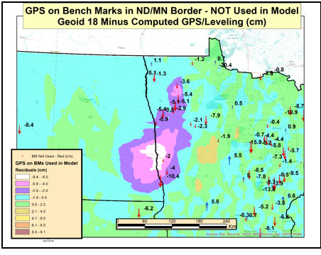
The box titled “Differences on GPS on Bench Marks in ND/MN Border — NOT Used in Model” depict the values of the rejected GPS on BMs stations. These stations were not used to create the hybrid geoid model Geoid18. As the plot indicates there are several large differences. This is not really surprising since these stations were not used in the model.
Differences on GPS on Bench Marks in ND/MN Border — NOT Used in Model
Image: National Geodetic Survey
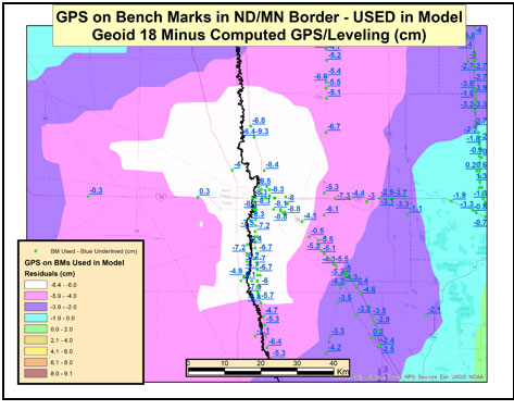
The box titled “Differences on GPS on Bench Marks in ND/MN Border — USED in Model” depict the values of the GPS on BMs stations used to create the Geoid18 model. Some of these differences exceed 8 cm. You would expect these differences to be small since these stations were used to create the model. So, why are there large post-modeled residuals in the Fargo, ND, region of the United States?
Differences on GPS on Bench Marks in ND/MN Border – USED in Model
Image: National Geodetic Survey
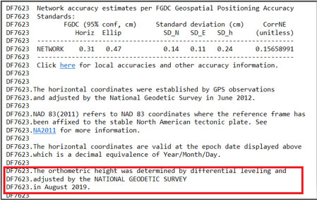
In August 2019, NGS performed a large leveling network adjustment in the Minnesota. The adjustment was performed after the Geoid18 database pull. The adjustment resulted in a 7- to 9-cm bias between the published height values and the superseded values. The August 2019 Minnesota leveling network adjustment heights were not used in the creation of Geoid18. The post-modeled differences presented in this column were generated using the published NAD 83 (2011) ellipsoid heights and current NAVD 88 orthometric heights from the NGSIDB. It was determined by NGS that the differences in the Fargo region were mostly due to crustal movement. Therefore, since the differences were due to movement, secondary adjustments will need to be performed to feather the 7- to 9-cm differences to maintain consistency between published NAVD 88 heights in the region. The secondary adjustments have not been completed as of the publication of this column so the residuals west of Fargo in North Dakota are small. These values will change after the secondary adjustment is completed and loaded into NGS’ database.
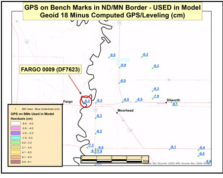
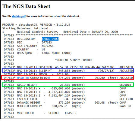
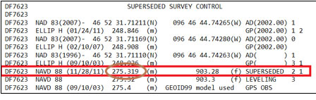
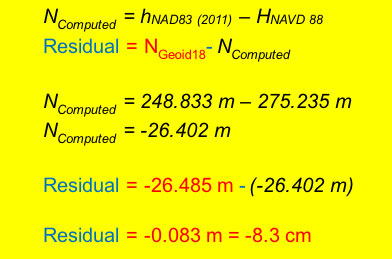
As an example, I’ve highlighted the station Fargo 0009 (PID DF7623) in the area of Fargo, North Dakota (see box titled “Differences on GPS on Bench Marks Near Fargo, ND”). The difference (-8.3 cm) is between the published Geoid18 value and the computed geoid value using the published ellipsoid height and orthometric height from the NGS’ datasheet. The box titled “Excerpt from Datasheet for Station Fargo 0009 (DF7623)” provides the information from NGS datasheet for station Fargo 0009; the information used in the computations are highlighted in the box. The box titled “Computation of the Difference between the Modeled Geoid Value (Geoid18) and the Computed Geoid Value for Fargo 0009” provides the process used to compute all differences for this column.
Differences on GPS on Bench Marks Near Fargo, North Dakota
Image: National Geodetic Survey
Excerpt from Datasheet for Station Fargo 0009 (DF7623)
Data: National Geodetic SurveyData: National Geodetic SurveyData: National Geodetic Survey
Computation of the Difference between the Modeled Geoid Value (Geoid18) and the Computed Geoid Value for Fargo 0009
(Information from NGS Published Datasheet)
Data: National Geodetic Survey
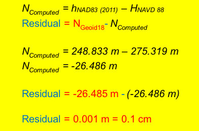
So, why is this difference so large in this region? A stated above, NGS performed a readjustment in this region and superseded the heights that were used in the creation of the Geoid18 hybrid model. The Geoid18 hybrid model used the previously published orthometric heights, now provided in the superseded section of the NGS datasheet, because that was the current published height at the time of the data pull for the Geoid18 process. Therefore, if we substitute the superseded height from the datasheet into the equation the difference is reduced to 0.1 cm (1 mm). [See the box titled “Computation of the Difference between the modeled geoid value (Geoid18) and the computed geoid value for Fargo 0009 Using the Superseded NAVD 88 Value.”]
Computation of the Difference between the modeled geoid value (Geoid18) and the computed geoid value for Fargo 0009 Using the Superseded NAVD 88 Value
(Information from NGS Published Datasheet)
Data: National Geodetic Survey
This means if someone uses NGS’ OPUS web tool to compute a GNSS-derived orthometric height, the NAVD 88 GNSS-derived orthometric height will be about 8 cm different than the published stations in this region. This should not be an issue if the users follow published NGS Guidelines to estimate the NAVD 88 GNSS-derived orthometric height, and/or uses NGS Beta OPUS-Projects and NGS procedures to estimate the NAVD 88 GNSS-derived orthometric height. These processes will ensure that the height will be consistent with the current published NAVD 88 orthometric heights in the NGS database.
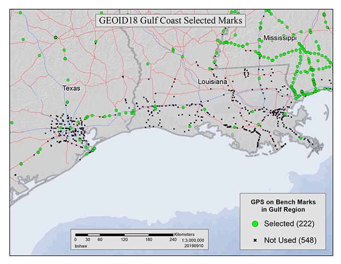
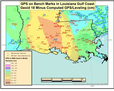
The technical report on Geoid18 provides a good explanation on the stations used in the United States Gulf Coast region. See box titled “GPS on Bench Marks for GEOID18 in the Gulf Coast Region.”
GPS on Bench Marks for GEOID18 in the Gulf Coast Region
There are areas of complex vertical crustal motion in the Texas/Louisiana Gulf Coast region of the United States which render many control station elevations in the region invalid. The selection of GPS on Bench Marks in this region was limited to the small number of marks where the leveling and GPS data agreed to minimize the influence of crustal motion in the hybrid geoid model. Figure 1 depicts the selection of stations used in the hybrid geoid model along the Texas/Louisiana Gulf Coast.
As indicated in the box titled “GPS on Bench Marks for GEOID18 in the Gulf Coast Region” very few stations in Southern Louisiana were used in the creation of the hybrid geoid model. The box titled “Differences on GPS on Bench Marks in the Gulf Coast Region” depict the differences between the published Geoid18 value and the computed geoid value using the latest NAD 83 (2011) ellipsoid and NAVD 88 orthometric height. The plot indicates that there are many large differences. This is to be expected because the orthometric heights used in the creation of the hybrid geoid model are all superseded heights. This is because the only published heights in Southern Louisiana are GNSS-derived orthometric heights and leveling-derived orthometric heights were used in the creation of GEOID18.
Differences on GPS on Bench Marks
in the Gulf Coast Region
Image: National Geodetic Survey
Saying that, NGS performed a large GNSS network project in Southern Louisiana in 2016. At the time of the writing of this column, the GNSS-derived orthometric height from the 2016 project were not yet finalized.
This column provided an analysis of the differences between the latest published hybrid Geoid18 values provided on NGS’ Datasheet and the computed geoid height value using the published NAD 83 (2011) ellipsoid height and NAVD 88 orthometric height. The column highlighted issues on differences due to published heights that have changed since the database pull for Geoid18. Future columns will address differences in other portions of CONUS.
Phase One Industrial, a provider of medium-format metric cameras and imaging solutions for aerial applications, has signed an agreement with AI-Survey GmbH, a developer of UAS survey packages, services and tailor-made solutions.
Together, the companies’ high-end products are opening up opportunities in drone-based high-accuracy mapping and inspection markets, the companies said.
Under this agreement, AI-Survey will support Phase One Industrial’s iXM range of cameras in the UAV market for high-accuracy mapping and inspection. AI-Survey offers fast and efficient, simple and reliable UAS solutions tailored for geodesists with millimetre imaging results.
“Our cameras exemplify AI-Survey’s mission to optimize, increase efficiency and inspire UAV mapping and inspection missions,”said Dov Kalinski, CEO, Phase One Industrial. “As an industry leader, we are confident that they will help our strategic efforts to evolve the industry through innovative solutions using Phase One Industrial technology.”
“We have developed long-term relationships and collaborations with many global technology partners, like Phase One Industrial,” said Carsten Rudolph, managing director, AI-Survey explains. “As an independent solutions provider, with such a large international network at our disposal, we are free to offer the best possible solutions to meet our customer needs and achieve their required accuracies. With Phase One iXM cameras, we now have the best global sensor for UAV mapping available, we believe.”
The interface adopts a concealed design for better protection, and USB type-C charging and transmitting is a two-in-one function.
The magnesium-alloy body is rugged and the battery level can be checked with a unique LED power indicator. The weight of the whole receiver is 940 grams.
The E300 Pro supports satellite station differential and satellite chain life, quick connection, intelligent voice, and tilt compensation. The E300 Pro tracks GNSS with 700 channels and fully supports BDS-3 signals. It supports 31 frequency points, using all GNSS satellite systems and frequency bands.
Inertial integration. The E300 Pro integrates multiple sensors including GNSS, an inertial measurement unit (IMU) , a magnetometer and a thermometer. With the help of a Kalman filter algorithm, the device can dynamically output position, speed and attitude information. It can measure and make real-time dynamic sampling without the need for leveling.
Combined GNSS Antenna. For better radio signal quality, the E300 Pro integrates GNSS, Bluetooth, Wi-Fi, 4G main and auxiliary antennas on the top of the receiver to ensure the best reception in all directions. An innovative RF connector greatly improves connection reliability, while reducing loss of gain.
Founded in 2005, e-Compass provides data acquisition and positioning equipment including high-precision GNSS receivers, GIS data collectors and combined inertial navigation products.The company is based in Shanghai, China, with offices in the United Kingdom and Hong Kong.
Qorvo, a provider of RF solutions, is acquiring Decawave, as well as Custom MMIC. Financial details have not been disclosed.
“This acquisition is by far the biggest in the indoor location industry,” according to Bruce Krulwich, founder of Grizzly Analytics. “While the price is not disclosed, I and others have estimated it at $400-500 million.”
“Apple is using their own UWB chips in upcoming iPhones, but their own chips are too big and use too much power to be used in smartwatches or other small devices,” Krulwich said. “Decawave’s chips will enable Qurvo to sell compatible UWB chips to a much wider range of markets.Apple’s use of UWB in iPhones is the tipping point for UWB. With Apple’s stamp of approval, UWB will be incorporated into a wide range of location-aware electronics, including robots, drones, wearables, smartwatches and more.”
“The biggest implications for this acquisition are not only in the RTLS market, but also in the areas of internet of things, wearables and location-aware electronics,” Krulwich said. “UWB is being used in next-generation products like drones by Intel, robots by iRobot, and autonomous vehicle movement by Segway.”
Bob Bruggeworth, president and chief executive officer of Qorvo, said in a third-quarter financial release that the company was “looking forward to welcoming two industry-leading teams, Decawave and Custom MMIC, to the Qorvo family, expanding our technology portfolio and product offerings.”
Decawave is an Irish fabless semiconductor company specializing in precise location and connectivity applications. The acquisition will advance market penetration of IR-UWB and enable broad global adoption of the technology.
Decawave was founded in Dublin in 2007 by current CEO Ciaran Connell and CTO Michael McLaughlin. The co-founders had a vision that the new IR-UWB technology, based on a nascent IEEE standard, could deliver ultra-accurate location in a way that would revolutionize people’s lives like GPS did in the 1990s.
Twelve years later, IR-UWB is on the verge of becoming the next essential component technology, like GPS, Wi-Fi and Bluetooth before it. Already shipping in millions of smartphones and cars, and across more than 40 other verticals, IR-UWB is enabling accurate indoor location services, secure communications, context aware user interfaces and advanced analytics.
“We are thrilled to announce the acquisition of Decawave by Qorvo,” said co-founder and CEO Ciaran Connell. “We have created an incredibly unique technology, but we understand that to embrace the opportunity in front of us, we will need greater resources to execute at scale, accelerate our innovation and product launches and to continue to support our growing customer base with the same level of service.
“Joining forces with Qorvo’s leading expertise in RF technology, their experience in serving very high-volume markets like Mobile but also the thousands of customers in Industrial and Enterprise, is, for Decawave, a perfect combination to scale and further accelerate the adoption of IR-UWB.”
Eric Creviston, President of Qorvo Mobile Products, said, “We’re very pleased to welcome the Decawave team, which we believe will enhance Qorvo’s product and technology leadership while expanding new opportunities in mobile, automotive and IoT. We look forward to building on the groundbreaking work that Decawave has done and helping to drive new applications and businesses using their unique UWB capability.”
Decawave co-founder Michael McLaughlin added, “From proving a new technology, to building new markets and to today joining a Tier 1 semiconductor company, the past 12 years have been a challenging and fantastic journey.
“None of this would have been possible without the dedication and passion of Decawave employees as well as the constant support from our lead investor Atlantic Bridge, Act Venture Capital, Summit Bridge, Enterprise Ireland and our business angels. To all others who accompanied us on this journey we also say a sincere and profound thank you and we look forward to the next chapter for IR-UWB.”
In the coming months and years Decawave and Qorvo will:
Continue to contribute to the IEEE, Car Connectivity Consortium, FiRa and UWB alliance to define next-generation PHYs and protocols, ensuring interoperability across applications and fueling IR-UWB adoption,
Accelerate the roadmap of ICs and modules, leveraging their respective R&D strengths and product portfolio to bring even more IR-UWB solutions to the market,
Pursue existing partnerships and investments in enablement to offer flexible and easy to integrate IR-UWB solutions to our customers.
Sapcorda Services GmbH has released its SAPA (Safe And Precise Augmentation) Premium GNSS positioning service.
The SAPA service enables mass-market GNSS devices to operate with increased accuracy and reliability across Europe and the continental United States. The service’s technology unlocks advanced performance with instantaneous sub-decimeter position accuracy for devices used in all market applications.
SAPA is delivered using the open industry-recognized SPARTN format, which allows efficiently delivery of the correction data via internet and satellite broadcast. “When using our service, users across Europe and the United States can experience homogeneous, gap-free, advanced positioning performance with any GNSS hardware designed for high precision positioning,” CTO Rodrigo Leandro said.
The SAPA service is tailored for mass-market applications including innovative mobility solutions, IoT applications, and traditional markets such as maritime.
SAPA was designed from ground up to support safety-critical applications such as autonomous driving.
SPARTN (Safe Position Augmentation for Real-Time Navigation) is a high-accuracy, open- and free-to-use GNSS format tailored for broadcast distribution in mass-market applications.
Sapcorda Services GmbH is a GNSS service provider focusing on the emerging high-precision GNSS mass markets. The company has designed its technology and service offering to serve high volume automotive, industrial and consumer markets.
What are the key technical criteria in matching GNSS receivers and antennas from the same or different manufacturers? For what uses does it matter most?
John Fisher. (Photo: Orolia)
“For fixed-pattern antennas, it’s fairly simple: RF + DC to power the antenna. Most vendors are compatible. The challenge is more for controlled radiation pattern antennas (CRPA). Power requirements vary greatly, and performance can be improved with a two-way data exchange between the CRPA and receiver, but there is no industry standard yet for this interface. An example: tilt angles from the receiver’s IMU can greatly aid beam pointing.” John Fischer Orolia
Ellen Hall
“Antenna selection is exceptionally critical for our military and high-precision users. The platform and environment are the primary drivers of these antenna requirements. In general, SWaP (size, weight and power) is at the forefront of all criteria. As operational plans are developed, requirements for a single or multi-element array, element gain, and noise figure must be considered.” Ellen Hall Spirent Federal Systems
Members of the EAB
Tony Agresta Nearmap
Miguel Amor Hexagon Positioning Intelligence
Thibault Bonnevie SBG Systems
Alison Brown NAVSYS Corporation
Ismael Colomina GeoNumerics
Clem Driscoll C.J. Driscoll & Associates
John Fischer Orolia
Ellen Hall Spirent Federal Systems
Jules McNeff Overlook Systems Technologies, Inc.
Terry Moore University of Nottingham
Bradford W. Parkinson Stanford Center for Position, Navigation and Time