Category: Applications

  • Receiver innovators log trends and product launches — Part 1

    Receiver innovators log trends and product launches — Part 1

    Cover photo: Topcon
    Cover photo: Topcon

    Lay of the GNSS Land

    Top receiver manufacturers discuss what’s on the horizon for GNSS receivers. The companies reveal recent and upcoming innovations, how to combat spoofing and jamming, fusing GNSS with other sensors, and the impact of increasing accuracy both for professional surveyors and consumers.

    With regard to jamming and spoofing, the preferred approach is a combination of monitoring, detection and filtering. However, shielding, the use of IMUs and other third-party sensors, and advances in processing algorithms also help mitigate interference. In a few years, hopefully, encrypted or “watermarked” signals will substantially reduce this problem.

    IMUs and other sensors are now routinely integrated with GNSS receivers, with their outputs fused. This trend is largely propelled on the demand side by the needs of the emerging market for autonomous vehicles and on the supply side by smaller, cheaper and more accurate IMUs and lidar scanners. Meanwhile, developments in algorithms have improved the modeling of errors to correct for the inherent tendency of IMUs to drift. Additionally, digital cameras, lidar and other industry-specific sensors are increasingly common, especially for collision avoidance in human-machine interactions.

    In surveying, the use of all constellations and frequencies, as they become available, is an industry trend. Costs will continue to drop as the growth in the adoption of GNSS solutions enables manufacturers to take greater advantage of economies of scale. Precise point positioning (PPP), which benefits greatly from the growth in GNSS constellations, is now giving real-time kinematic (RTK) positioning a run for its money. Available applications enable Android mobile devices to achieve centimeter accuracy, while innovations continue in core positioning algorithms.

    In the world of mobile consumer devices, dual-frequency, multi-constellation GNSS chipsets are increasingly prevalent. As increased accuracy fuels expectations for even higher accuracy, precision positioning may become the norm in the consumer space, and new applications for these devices may emerge. Already, crowdsourcing the monitoring of both GNSS signals and interference helps improve accuracy for everyone, in a positive feedback loop.

    Other notable trends include the introduction and expansion of 5G data networks, the increased use of satellite-based correction services, and continued efforts to develop precise positioning for indoor areas. (See part 2 of this feature here.)


    Topcon

    Jamming and Spoofing. “We continue to develop and deploy patented technology to detect spoofing,” said Alok Srivastava, director, product management. “We already have cutting edge GNSS antenna technology to provide stellar support for interference rejection and filtering.” All Topcon end products have this advanced antenna and filtering technology.

    Sensor Fusion. “Topcon has been using inertial systems for decades for a variety of positioning applications — such as machine control, mobile mapping, and agriculture,” said Srivastava. “In recent years, advancements in IMU technology have progressed to where the size and cost of these sensors are at levels to be utilized at a larger scale. For example, the recently released Topcon HiPer VR takes advantage of inertial technology to improve productivity in real time with our Topcon Integrated Leveling Technology (TILT), which compensates for mis-leveled field measurements out of plumb by as much as 15 degrees.”

    Surveying. Topcon continues to invest in its core positioning algorithms to innovate such features as quartz lock loop, advanced multi-engine platform, and VHD heading technology into its positioning engines, Srivastava said. “We also produce solutions such as our Millimeter GPS and Hybrid Positioning innovations, which are designed around improving accuracy, higher reliability, and greater flexibility by converging positioning technologies.”

    Consumer Devices. “GNSS in consumer devices and other commercial systems is used to aid other positioning sensors,” Srivastava said. “So, it may not be in the best of interest to offer that level of accuracy from GNSS alone.”

    Other Challenges. Precise indoor positioning is a requirement of the vertical construction industry. “Topcon’s combined optical instrument takes a unique approach to solve that problem by integrating a compact laser scanner with a fully featured robotic total station,” Srivastava said.

    Photo: CHC Navigation
    Photo: CHC Navigation

    CHC Navigation

    Jamming and Spoofing. CHCNav is currently taking a twofold approach to GNSS interference, said François Martin, vice general manager, International Division. “As a GNSS system integrator, we focus our design around strong electromagnetic shielding and sealed isolation chambers.” Additionally, he pointed out, the advanced filtering of GNSS signals and an antenna patch produce optimal interference mitigation.

    Sensor Fusion. Integrating interference-free, high-dynamic IMUs instead of MEMS has brought the full benefits of tilt compensation to users, Martin said. The latest development in algorithms dramatically obviated the need for the annoying process of initializing GNSS IMU receivers and boosted the availability of GNSS RTK in demanding environments.

    Surveying. The fast adoption of GNSS solutions by large user segments has reduced costs by enabling a sizable manufacturing economy of scale, Martin pointed out. “Tighter combination of embedded technologies such as GNSS and connectivity modules are sustaining that cost reduction process.”

    Consumer Devices. “The emergence of dual frequency multi-constellation GNSS chipsets supports the development of untapped user segments, but the position accuracy repeatability remains an issue,” Martin said. “The integration of GNSS chipset and high-performance helical antennas, as precision add-on modules, onto rugged Android cell phone and tablets is creating a prosumer-grade centimeter to decimeter accuracy answering to a wide range of mobile workforce applications.”

    Other Challenges. A growing number of positioning and navigation applications require the fusion of technologies to increase productivity, Martin said. “The integration of advanced tightly integrated positioning algorithms, scanners, IMUs, HDR cameras, IoT and cloud-based connected solutions are a clear trend.” However, their adoption by a large user base remains limited by their current price point.


    Photo: Septentrio
    Photo: Septentrio

    Septentrio

    Jamming and Spoofing. “Recent developments in receiver-antenna combinations maximize the benefits of anti-jamming techniques,” said Gustavo Lopez, market access manager. Third party sensors, such as IMUs, also help mitigate interference, he pointed out. “Septentrio’s advanced receiver technology such as AIM+, a standard feature on all the company’s products, bring not only real time monitoring but also jamming/spoofing mitigation. Galileo and GPS have clear roadmaps bringing signal authentication in order to avoid spoofing.”

    Sensor Fusion. Smaller IMUs with higher grade performance now on the market are enabling new use cases in autonomous applications, said Lopez. Other important elements are a new generation of compact high-performance sensors and the growing importance of multi-sensor technology “to provide even higher levels of positioning integrity.” He cited Septentrio’s AsteRx-i family of products as an example of GNSS/INS integrated solutions.

    Surveying. As an example of Septentrio’s survey-specific products, which “continuously benefit from advanced developments being rolled out in our platform,” Lopez cited the Altus NR3.

    Consumer Devices. The increasing positioning accuracy of cell phones, Lopez pointed out, “has spurred innovations such as PPP and the use of mobile phone measurements,” as well as “other purposes, such as interference detection and crowdsourcing.”

    Other Challenges. “Sensor fusion is a key element in positioning and orientation,” Lopez said. “Easy integration is a key element in this trend. Also, integrity in error reporting and positioning will be required as well as reliable raw measurements which can be integrated with other sensors. This drives the requirement for receivers capable of running customer proprietary software. Another important element will also be the possibility of running positioning algorithms on a third-party processor.”
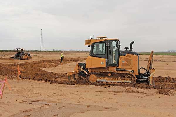

    Photo: Hemisphere GNSS
    Photo: Hemisphere GNSS

    Hemisphere GNSS

    Jamming and Spoofing.Hemisphere’s new Lyra II ASIC platform used in our Phantom and Vega series positioning and heading boards,” said Miles Ware, director of marketing, “introduces new technology and filtering methods to identify and mitigate known and unknown interference sources that typically have an adverse effect on GNSS performance.”

    Sensor Fusion. “Advancements in IMU integration and sensor fusion,” Ware said, “will continue to be a key focus for Hemisphere to support the growth and adoption of the expanding autonomous vehicle and application marketplace. The positioning and heading technology offered in our Vega 28 will be a core component for autonomous marine, machine control, and agriculture solutions for new and emerging markets.”

    Surveying. “Access to modern and future signals like BeiDou Phase III, ALTBOC and BS-ACEBOC significantly enhance GNSS accuracy, especially in challenging environments where satellite visibility is compromised by the topography and or the structures present,” Ware pointed out. “Survey solutions that can not only track but also use all the available GNSS measurements in their RTK solution will have a substantial advantage in the market.”

    Consumer Devices. “As mobile phones and consumer devices continue to adopt hardware designs that can access the latest GNSS signals,” Ware said, “the opportunities for solutions where high precision measurement engines can be hosted within mobile devices opens up a new realm of solutions that can leverage the high accuracy positioning performance found in Hemisphere technology and products. We see this as a very exciting and emerging area.”

    Other Challenges. Ware pointed to “leveraging GNSS technology to further support environmentally friendly transportation solutions and sustainable agriculture,” for which GNSS continues to be an integral component.


    Photo: Unicore
    Photo: Unicore

    Unicore Communications

    Sensor Fusion. “We are implementing GNSS with different level IMUs, including low-cost and high-end, targeting automotive, intelligent driving, and robot application scenarios,” said Gao Jingbo, marketing director. “The algorithm can also integrate with the already-existing sensors on the platform, such as IMUs, cameras and odometers. The solution can be done on the GNSS side, with high information synchronization accuracy, or processed on the platform.”

    Surveying. Products with Unicore boards inside can provide centimeter- to millimeter-level positioning accuracy, said Jingbo. “Unicore’s high-precision boards and modules can track all frequencies of all satellite systems. The UGypsophila RTK technology can make the most of the observation data of all frequencies in all systems even without the observations of the base station in the RTK solution, thus greatly improving the usability, reliability and accuracy of RTK.” The company is now also working to reduce the dimensions and cost of its products, Jingbo pointed out. “With Unicore’s single GNSS SoC on board, the UB4B0M and UM4B0 modules are making affordable high-end high precision surveying possible.”

    Consumer Devices. Algorithms and hardware are ready now to implement PPP+RTK in cell phones, Jingbo said, and this increase in positioning accuracy will enable many more applications. “We have rich experience in high precision GNSS, but the antenna might be a challenge. Our new generation 22 nm GNSS SoC features low power consumption and support of sensor fusion. Additionally, true point technology by Rx-Networks (also a BDStar company) can provide sub-meter data service, which also enables users to access centimeter-level accuracy location data through their mobile phones and wearable technologies, without increasing the demand for processing power.”


    Photo: Trimble
    Photo: Trimble

    Trimble

    Jamming and Spoofing.Trimble’s latest GNSS receivers leverage our seventh-generation Maxwell technology, which implements hardware- and software-based techniques to detect and mitigate spoofing,” said Stuart Riley, vice president, GNSS Technology. “In addition, Trimble continues to improve the robustness of our GNSS receivers with advances in processing algorithms and hardware enhancements such as the integration of inertial technology.”

    Sensor Fusion. “For many years, IMUs have been widely used in Trimble agriculture and Applanix products,” Riley said. “Over the past few years, we’ve created a new line of lower-cost inertially integrated board-level GNSS receivers. We have also integrated inertial components into survey and construction products, including tilt compensation in the Trimble R10, R12 and SPS986 receivers. Trimble also combines its GNSS solutions with optical, laser, lidar and other sensors.”

    Surveying. Trimble’s GNSS products, Riley pointed out, range from GIS handhelds to high-performance mobile mapping systems.

    Consumer Devices. “The Trimble Catalyst system uses Android-based smartphones or tablets to run an application that includes a software-defined GNSS receiver,” Riley said. “The recently introduced SiteVision system builds on this ecosystem and integrates Google’s ARCore platform with precision GNSS to provide an augmented reality solution for a variety of professional applications.”

    Other Challenges. To address signal masking and multipath, Trimble has “continued to improve performance in difficult environments with products such as the Trimble R12 receiver, which provides sophisticated multipath mitigation and an advanced precision processing engine.” Riley said, “Trimble’s RTX Correction Services, delivered via satellite, enable users to achieve RTK speed and accuracy nearly anywhere on the planet without the need for local reference stations.”


    Photo: NovAtel
    Photo: NovAtel

    NovAtel

    Jamming and Spoofing. “The RF environment is at best crowded and at worst hostile,” said Sandy Kennedy, vice president of innovation, Hexagon’s Positioning Intelligence division. “The NovAtel OEM7 generation of receivers was launched in 2016, with interference detection and mitigation as key features on every variant. Protecting authenticity, availability, and precision for multifrequency measurements is the challenge going forward — in all segments of the system: constellation management and SIS, antenna, receiver design and processing in FW/SW.”

    Sensor Fusion. In the last three years, Kennedy pointed out, IMU manufacturers have made significant improvements in the performance offered in smaller, cheaper IMUs. “At the same time, new methods to improve error modelling (to control positioning errors) have been added to the NovAtel SPAN product line, especially in SPAN Land profile. Extended GNSS outages are easily handled now.”

    Surveying. “PPP has become a strong competitor to RTK, as convergence times have decreased, and this will continue in service offerings like Terrastar-X from NovAtel,” Kennedy said.

    Consumer Devices. The devices, Kennedy said, offer “the tantalizing promise of quality measurements from a common utility device with huge computing horsepower and data connectivity built in! It’s fun to watch, and we shall see if accuracy is truly addictive enough to fuel development for general use of precision positioning.”

    Other Challenges. “In the past 20 years, users have moved from awe and wonder that centimeter-level positioning is possible — to utter contempt when it is not,” Kennedy said. “This will continue, with an added requirement of integrity and functional safety. Continuously available positioning within a usable protection level is a requirement for autonomous vehicles.”

    Also read part 2 from our February issue, and our antenna feature.

  • Automated shipping moves containers with Locata

    Automated shipping moves containers with Locata

    At ION GNSS+ in September, I met with Nunzio Gambale and Paul Benshoeff of Locata. They were excited to share their news about the timing tests conducted at White Sands Missile Range by the U.S. Air Force’s 746th Test Squadron.

    In the January issue, we share the results of the tests. The two also showed me and Matteo Luccio, our contributing editor, a YouTube video highlighting another Locata project: guiding 100-ton robots around the Ports of Auckland, New Zealand.

    The robots are straddle carriers, giant mechanisms that are usually driven by a human. The carriers move and sort the shipping containers as they arrive from ships and leave via truck or train.

    In the new setup, Locata has made possible the elimination of the human element with nanosecond-precision tracking.

    Tom Scott, a former Sky One television host and now host of a series of YouTube shows, highlighted the robotic system in April 2019 on his “Amazing Places” channel.

    Screenshot: Tom Scott video
    Screenshot: Tom Scott video

    Compared to manned straddle carriers, the automated straddle carriers (A-STRADs) are able to stack the containers closer, higher and work more steadily, increasing the capacity of the limited land space at the port. The A-STRADs can stack containers with the accuracy of a few centimeters.

    The automated system also allows stack shuffling, so that wear and tear on the asphalt is spread more evenly and requires fewer repairs.

    The Locata local positioning system uses synchronized transmitters installed around the port, with two antennas on each straddle carrier using the lightspeed delay from each transmitter to find exact position. “They don’t just look at the timing signal itself, they track the phase of each transmitter’s carrier signal,” Scott explained.

  • Bluesky launches MetroVista 3D city models online

    San Francisco. (Image: Bluesky)
    San Francisco. (Image: Bluesky)

    Highly accurate, UK city-wide 3D models are now available to view and download from Bluesky’s online Mapshop.

    The geographically accurate, photo-realistic MetroVista mesh models are available in a variety of formats ready for use in 3D GIS, CAD and other modelling software as well as visualisation, gaming and Virtual Reality workflows.

    Captured using Leica’s large-format imagery and lidar hybrid airborne sensor and generated in Skyline’s PhotoMesh software, the Bluesky MetroVista datasets of major UK cities are available online offering a compelling alternative to traditional photogrammetrically produced models.

    Now in America. In December, Bluesky launched its 3D data capture programme in the United States. The MetroVista product suite allows high-resolution imagery, both vertical and oblique, to be captured simultaneously with high-accuracy, wide-scale 3D data using an advanced Leica camera, the  CityMapper. Specifically designed for 3D city modeling and urban mapping, the system includes a traditional vertical camera as well as survey-grade oblique cameras.

    The CityMapper also includes high-performance lidar technology to accurately collect elevation data — even in shadows that are common in urban environments and can make photo-based collection difficult.

    “Since launching in the UK the MetroVista product range has received enormous offline interest from sectors such as infrastructure and building development, risk assessment, telecommunications and environmental mapping,” said Rachel Tidmarsh, managing director of Bluesky. “By making the data easy to access and consume via our online Mapshop, we hope to increase the take up from traditional users of 3D models and encourage applications such as smart city management, autonomous vehicle testing, virtual reality experiences and gaming.”

    Two seasons in the UK

    Bluesky has been capturing MetroVista data in the UK for two flying seasons. Visitors to Bluesky’s Mapshop will initially be able to select an area and download MetroVista mesh models of London, Birmingham and Cambridge with other UK and U.S. cities coming online in the future.

    Data can be supplied in a variety of proprietary and open source formats including OBJ, FBX, I3s and 3DML for use in Skyline’s TerraExplorer product suite.

    The Bluesky Mapshop also offers complete nationwide coverage of aerial photography from multiple epochs, 3D models, lidar data, thermal mapping and Bluesky’s National Tree Map. Blueskymapshop.com is easy to use and purchasing of data is simple, straightforward and secure. Account options are also available and data can be purchased with a range of easy to understand licence options, including the option of a Sub Contractor Licence.

  • Ole Miss students get meals delivered by robots

    Ole Miss students get meals delivered by robots

    Photo: Christian Johnson/Ole Miss Digital Imaging Services
    Photo: Christian Johnson/University of Mississippi

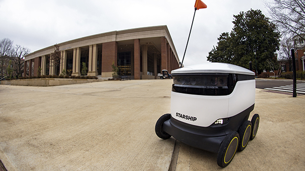
    As University of Mississippi (UM) students resume classes for the spring semester, they are sharing the campus’ sidewalks with a fleet of robots that can deliver meals at the push of a button.

    Starship Technologies has launched robot food delivery services at the university, the first in the Southeastern Conference to have autonomous delivery robots.

    Beginning Jan. 22, Ole Miss students, faculty and staff can access the Starship Deliveries app (iOS and Android) to order food and drinks to be delivered anywhere on campus, within minutes from any of the 30 robots serving UM. The service will work in conjunction with student meal plans.

    Ole Miss Dining is focused on the continued utilization of advanced technology to enrich the student, faculty and staff dining experience,” said Chip Burr, resident district manager of Ole Miss Dining Services. “We are excited about the expansion of our mobile ordering operation and the new opportunities this partnership creates.”

    The robots use a combination of sophisticated machine learning, artificial intelligence and sensors to travel on sidewalks and navigate around obstacles. The computer vision-based navigation helps the robots to map their environment to the nearest inch. They can cross streets, climb curbs, travel at night and operate in both rain and snow.

    A team of humans also can monitor their progress remotely and take control if needed.


    By making food and drink more accessible, the Starship robots save time and reduce stress, aiming to make the busy lives of the Ole Miss community a little easier, Burr said.

    Items can be ordered from Starbucks, Chick-fil-A, McAlister’s, Panda Express, Which Wich, Qdoba, Einstein Bros. Bagels, Raising Cane’s, Steak ‘n Shake, Freshii, Papa John’s and Sambazon. After choosing their items, users select their location by dropping a pin on the campus map where they want their food delivered.

    The app allows users to watch the robot’s journey in real time through an interactive map. Once the robot arrives, the user will receive an alert and can meet the robot and unlock it through the app.

    The delivery usually takes just minutes, depending on the menu items ordered and the distance the robot must travel. The robots can carry up to 20 pounds.

    Starship Technologies operates commercially on a daily basis around the world. Its robots have traveled more than 350,000 miles and completed 100,000 autonomous deliveries.

    “We’re honored to be able to help make lives a little bit easier for Rebels across the Ole Miss campus by offering the world’s leading autonomous delivery service,” said Ryan Tuohy, senior vice president of business development at Starship. “Whether it’s getting breakfast delivered in the morning or having a late-night snack, our robots are here to serve students, faculty and staff at all times of the day.”

  • Audi, Qualcomm and Virginia DOT to deploy C-V2X

    Audi, Qualcomm and Virginia DOT to deploy C-V2X

    Audi of America, the Virginia Department of Transportation (VDOT) and Qualcomm Technologies Inc. are planning for initial deployments of cellular vehicle-to-everything (C-V2X) communication on northern Virginia roadways.

    C-V2X employs advanced wireless communications to enhance vehicle safety by using the same portion of the 5.9-GHz band that the Federal Communications Commission (FCC) has proposed to allocate for C-V2X.

    In line with the Federal Department of Transportation’s announcement to establish a First Responder Safety Pilot Program, the organizations’ combined efforts are designed to focus on improving safety for construction workers and motorists.

    The initial deployment is expected to take place on select roadways in Virginia beginning in the third quarter of this year.

    C-V2X will be used to deliver work zone warnings on highways as well as signal timing information on approaches to signalized intersections on arterial roadways. In both cases, C-V2X communications can help deliver critical safety messages between vehicles and infrastructure with minimal latency, while less time-sensitive alerts are designed to be provided via C-V2X using the cellular network.

    Photo: Audi
    Photo: Audi

    The initial deployments are aimed at expanding safety use cases in the connected vehicle safety spectrum established by the FCC, with the aim to curtail road hazards and fatalities. In a given year, traffic fatalities in the U.S. exceed 36,000 people.

    The initial deployment is designed for connected-car systems designed to

    • boost safety around school buses,
    • warn motorists about dangerous road conditions,
    • alleviate congestion at traffic chokepoints and curbsides,
    • help improve the performance of automated vehicles that are nearing commercialization
    • potentially let cars communicate with mobile devices to send warnings that may one day help prevent the more than 6,000 pedestrian fatalities per year.

    The northern Virginia initial deployment involves two primary use cases:

    • Work zone warnings, which the organizations feel is an important use case on highways, featuring a Qualcomm 9150 C-V2X chipset solution via an in-vehicle display in Audi Q8 SUVs designed to deliver a graduated warning, with the last link being a low-latency, reliable warning to drivers of the workers’ physical presence.
    • On arterial roadways, the signal phase and timing (SpaT) from a traffic signal, will be transmitted with a Qualcomm 9150 C-V2X chipset solution to Audi Q8 SUVs. These vehicles have the Audi Traffic Light Information (TLI) service that can provide drivers a countdown to the green light. C-V2X from the traffic signal can also provide direct information to the Audi Q8, which will be used by the TLI system to fine-tune the countdown information of the signal phase and timing.

    “VDOT has long supported research into the benefits of connected and automated vehicles, particularly those aspects that have the potential to significantly enhance safety,” said Virginia’s Director of Transportation Research and Innovation Cathy McGhee. “The inclusion of shorter-range, direct communication in the 5.9 GHz band using C-V2X is exciting, as it can allow us to evaluate this emerging communication option for essential and practical safety and mobility services, including saving the lives of maintenance and construction personnel in work zones.”

    Photo: Audi
    Photo: Audi

    “We recognize the immediate value of the spectrum that the FCC proposed to allocate to C-V2X, and we endeavor to show our V2X equipped cars on real roads engaging in how transportation safety and mobility could be jump-started,” said Anupam Malhotra, Director, Connected Vehicle Services, Audi of America. “We are excited about our participation in this pilot deployment as it highlights the broad societal advantages that technology is now poised to deliver through the full 5.9 GHz V2X spectrum near term with far, far more to come as connected and automated vehicle fleets emerge over the next decade.”

    Audi’s Traffic Light Information V2X services operate in 25 cities and nearly 10,000 intersections nationwide, including more than 1,700 intersections in the Washington D.C. metropolitan region.

    “Qualcomm Technologies is excited to work with the VDOT, through its partner Virginia Tech and Audi to support the C-V2X use cases on the very same spectrum that the FCC has proposed to allocate for C-V2X. Qualcomm Technologies has long been a pioneer in the connected car with over 20 years of experience delivering in-vehicle telematic systems,” said Jim Misener, senior director, product management, Qualcomm Technologies, Inc. “With the advances in cellular communications now enabling us to also offer direct connectivity for safety services, traffic efficiency and emerging automated use cases, we are pleased to work closely with VDOT, Audi of America and Virginia Tech to showcase the commercial maturity and technological sophistication of C-V2X and to start the proliferation of the technology on U.S. roadways.”

    The Virginia Tech Transportation Institute (VTTI) will develop the software and systems to support the primary use cases defined for the initial deployment. Following software development, the institute will then conduct a demonstration of C-V2X technology operating in these use cases.

    C-V2X Features and Benefits

    • The C-V2X solution used in this initial deployment is based on third-generation partnership project (3GPP) Release 14 and Release 15 specifications. Direct communication of this solution uses 20 MHz from the 5.905 – 5.925 GHz ITS band, the same spectrum that the FCC has proposed allocating for C-V2X.
    • A more advanced mode of C-V2X has an evolution path to 5G using 3GPP Release 16 specifications.
      Field test results issued by the 5G Automotive Association (5GAA) have proven C-V2X to be an efficient and effective radio access technology, showing that it significantly increases in range and reliability compared to other radio technologies.
    • C-V2X commercial products are now widely available in the form of multiple chip platforms, wireless modules, vehicular Onboard Units and infrastructure Roadside Units.
    • C-V2X encompasses both direct short-range communications that operate in the 5.9GHz ITS band and longer-range network communications delivered by mobile network operators; chipsets now offer both direct and network connectivity in the same solution concurrently, aiding in the adoption of the technology.

    For more information about the Traffic Light Information technologies on Audi models in select markets, visit www.media.audiusa.com.

  • U-blox L-band receiver enables cm-level positioning for mass market

    U-blox L-band receiver enables cm-level positioning for mass market

    Photo: u-blox
    Photo: u-blox

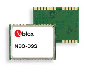
    U-blox said its new NEO-D9S GNSS correction data receiver module provides an affordable approach to bringing centimeter-level accuracy to GNSS receivers.

    The NEO-D9S receives from correction service providers broadcast on the L-band (1525-1559 MHz). A host processor can then decrypt this correction data and provide it to a high-precision GNSS receiver, combining corrections directly with readings from the satellite constellations to enable much more accurate position readings than those offered by GNSS signals alone.

    Use of the NEO-D9S will also increase the availability of high-precision GNSS positioning data in areas with limited connectivity and reduce the amount of cellular data consumed by positioning receivers.

    Customers are expected to include carmakers, both Tier 1 and OEMs, industrial system integrators that offer position-correction services, and any other applications that rely on very accurate positioning at low cost.

    The NEO-D9S module is a correction-only receiver, based on the latest u-blox ninth-generation (D9) platform. This means that it will integrate easily with the u-blox F9 RTK GNSS receivers from u-blox, or can be used as part of a modular product roadmap. The module also integrates a TCXO and SAW filter to ensure good RF sensitivity and resilience to interference from adjacent channels.

    The module includes the algorithms necessary to decode satellite data broadcasts. It is configured to work initially with whichever correction service has been set as default, but can be configured for any L-band data broadcast. It stores its configuration settings in non-volatile memory.

  • Qualcomm launches 3 dual-frequency + NavIC smartphone modules

    Qualcomm launches 3 dual-frequency + NavIC smartphone modules

    New modules enable entertainment, advanced connectivity features and next-generation artificial intelligence

    Qualcomm Technologies has launched three new mobile platforms — the Qualcomm Snapdragon 720G, 662 and 460 — to enable enhanced user experiences across connectivity, gaming and entertainment.

    The new mobile platforms support dual-frequency (L1 and L5) GNSS to improve location positioning accuracy and robustness. The system-on-chip solutions also support the Indian NavIC (Navigation with Indian Constellation).

    Seven constellations. For the first time supported on mobile, the Qualcomm Location Suite now supports up to seven satellite constellations concurrently, including the use of all of NavIC’s operating satellites for more accurate location performance, faster time-to-first-fix (TTFF) position acquisition, and improved robustness of location-based services.

    “ISRO is satisfied with the efforts of Qualcomm Technologies Inc. towards incorporating NavIC and we urge OEMs to leverage it for future handset launches in India,” said K. Sivan, chairman, ISRO. “The availability of NavIC across multiple mobile platforms will help enhance the geolocation capabilities of smartphones in the region and bring the benefits of this indigenous solution to Indian consumers for their day-to-day use.”

    The new modules also enable fast 4G connectivity speeds, deliver key Wi-Fi 6 features and integrated Bluetooth 5.1 with advanced audio via the Qualcomm FastConnect 6-series subsystems.

    Artificial Intelligence. Designed to deliver new and improved AI user experiences across photography, voice assistants and virtually always-on scenarios for increased contextual awareness, the new platforms also feature the Qualcomm AI Engine and Qualcomm Sensing Hub.

    “While we see a fast adoption of 5G across geographies globally, we do recognize the phenomenal boost that 4G has given towards enabling broadband connectivity for Indian consumers. 4G will continue to remain a focus area for Qualcomm Technologies for regions like India, where it will stay a key technology for connectivity,” said Rajen Vagadia, vice president and president, Qualcomm India Pvt. Ltd. “Our goal is to enable our partners to continue creating solutions that offer seamless connectivity access and exceptional mobile experiences, that consumers can count on.”

    “Today’s smartphone users want fast, seamless connectivity, advanced features and long-lasting battery life,” said Kedar Kondap, vice president, product management, Qualcomm Technologies, Inc. “This expansion of our 4G lineup enables our partners to offer sophisticated solutions that meet global demand and enable a remarkable gaming experience across multiple tiers and price segments.”

    Photo: Qualcomm
    Photo: Qualcomm

    Snapdragon 720G

    Snapdragon 720G reimagines extraordinary gaming and entertainment experiences with select Qualcomm Snapdragon Elite Gaming features, striking capture capabilities, and intelligent performance. Leveraging select Snapdragon Elite Gaming features from premium-tier mobile platforms, Snapdragon 720G delivers smooth HDR game play, dynamic color range and contrast, realistic and immersive in-game environments, and high-quality, synchronized sound with Qualcomm aptX Adaptive.

    In addition to gaming, users will have a “home theater in their pocket” with HDR viewing and super-smooth video streaming with the Qualcomm Spectra 350L ISP, Qualcomm said. They can also capture 4K video or snap massive 192-megapixel photos.

    Snapdragon 720G also features the latest fifth-generation Qualcomm AI Engine with the improved Qualcomm Hexagon Tensor Accelerator that will enable a host of new AI experiences for gaming, photography, voice assistants and virtually always-on contextual awareness.

    The integrated Snapdragon X15 LTE modem supports 3-carrier aggregation, 4×4 MIMO on two carriers and 256-QAM modulation for fast download speeds up to 800 Mbps — allowing for quick app downloads and smooth video streaming and sharing.

    In addition, Snapdragon 720G, with the FastConnect 6200 subsystem, virtually doubles Wi-Fi speed and range for online gaming and web browsing, compared to single antenna devices, while also delivering key Wi-Fi 6 features such as 8×8 sounding with multi-user MIMO for up to 2x improvement over competitive Wi-Fi 6 devices, Target Wake Time for up to 67% better power efficiency and the complete WPA3 security suite, as well as integrated Bluetooth 5.1 with advanced audio capabilities.

    Finally, users will experience power savings and improved performance due to the Snapdragon 720G’s 8-nm process technology and upgraded CPU architecture.

    Snapdragon 662

    Snapdragon 662 brings astonishing camera and AI capabilities to the 6-series for the first time. It will feature the new Qualcomm Spectra 340T, which supports triple camera configurations and smooth switching between them — a first in the 6-series. A more robust ISP will enable support for photo capture in the HEIF file format for stunning image quality at half the file size.

    The addition of the third-generation Qualcomm AI Engine with Hexagon Vector Extensions and the Qualcomm Spectra 340T will enable AI-based user experiences such as avatars, night photography, and face and voice authentication.

    Snapdragon 662 also features the new Snapdragon X11 LTE modem with peak download speeds up to 390 Mbps thanks to 2-carrier aggregation, 2×2 MIMO and 256-QAM modulation, along with 150 Mbps peak uploads to support a snappy web browsing and social media experience.

    Snapdragon 460

    Snapdragon 460 boasts a gigantic leap in performance across the board in the 4-series, as well as significant boosts in connectivity, AI and camera improvements[1] for the next-generation of mass market smartphones. For the first time in the 4-series, Snapdragon 460 features performance CPU cores and an updated GPU architecture that translates into up to 70% and 60% increase in performance, respectively.

    Overall system performance, meanwhile, delivers a 2x increase compared the previous generation. The Hexagon processor with Qualcomm Hexagon Vector eXtensions (HVX) is also introduced into the 4-series for the first time, thereby equipping it with a 3rd generation Qualcomm AI Engine and the Qualcomm Sensing Hub for new AI experiences for photography and voice assistance.

    The Qualcomm Spectra 340 ISP is also among the many new additions to the 4-series, enabling the platform to capture stunning photographs and support for triple cameras. An integrated Snapdragon X11 LTE modem allows for download speeds up to 390 Mbps and uploads up to 150 Mbps.

    To date, more than 85 commercial devices based on Snapdragon 7-series mobile platforms, more than 1600 commercial devices based on Snapdragon 6-series mobile platforms, and more than 2,500 commercial devices based on Snapdragon 4-series mobile platforms have been announced by global OEMs. Together, the 7-, 6- and 4-series amount to over 4,000 designs — an impressive feat for these segments.

    Devices based on Snapdragon 720G are expected to be commercially available in Q1 2020 and devices based on Snapdragon 662 and 460 are expected to be commercially available by the end of 2020. For more information, please visit the product details pages for the Snapdragon 720G Mobile Platform, Snapdragon 662 Mobile Platform, and Snapdragon 460 Mobile Platform.

  • Airbus reminds pilots what to do when GNSS interference hits

    Airbus reminds pilots what to do when GNSS interference hits

    Airbus is providing safety information to all pilots, not just those of the new BelugaXL. (Photo: Airbus)
    Airbus is providing safety information to all pilots, not just those of the new BelugaXL. (Photo: Airbus)

    Commercial airline pilots should be ready if their GNSS interference or jamming takes place. This safety message, along with steps to take, was provided by Airbus in the January issue of its publication “Safety First.”

    In the publication, Airbus is reminding pilots of the consequences and required action in the cockpit, according to Aviation Week. Loss of the GNSS signal can affect navigation and surveillance functions. While built-in redundancies will maintain position computation, up to a dozen systems and functions can be affected.

    Cover: Airbus
    Cover: Airbus

    “A loss of GNSS inputs does not lead to a map shift or an erroneous position computation by the FMS (Flight Management System). In the case of a loss of GPS signal, the FMS switches from the mixed GPS/IRS position to an IRS-DME/DME position or IRS-VOR/DME or pure IRS, in order of priority,” the experts explain in the publication.

    Other affected systems can include the predictive functions of the terrain awareness and warning system, the runway overrun protection system, and ADS-B Out, in which case pilots should notify air traffic control.

    Once the flight is over, pilots should report the GNSS interference event to air navigation service providers.

  • Marine vessels to use Oceaneering C-Nav positioning

    Oceaneering C-Nav Positioning Solutions to provide C-Nav5000 GNSS receivers for select SEACOR marine vessels

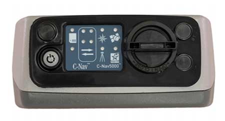
    The C-Nav5000 GNSS receiver. (Photo: Oceaneering)
    The C-Nav5000 GNSS receiver. (Photo: Oceaneering)

    Oceaneering C-Nav Positioning Solutions has been selected by SEACOR Marine to supply C-Nav5000 GNSS receivers for a select number of the company’s oil-and-gas support vessels worldwide.

    The scope of work calls for C-Nav to provide two C-Nav5000 GNSS systems per vessel. SEACOR will license corrections signals from C-Nav while the equipment is onboard and the vessels are working. C-Nav expects to install the C-Nav5000 receiver on seven vessels by year’s end.

    “We are delighted to have been selected by SEACOR to provide our precise point positioning receivers onboard their vessels,” said David Fitts, senior manager, C-Nav Positioning Solutions. “Our receivers will provide SEACOR vessels with the latest in GNSS hardware.”

    The C-Nav5000 offers integrated GNSS capabilities that allow tracking of multiple systems. It features triple L-band channels for correction tracking and is software-configurable to user requirements.

  • Research Roundup: Focus on maritime

    Research Roundup: Focus on maritime

    The 18,000-container-capacity CMA CGM Kuergelen. (Photo: CMA CGM)
    The 18,000-container-capacity CMA CGM Kuergelen. (Photo: CMA CGM)

    Of the 273 papers researchers presented this year at the Institute of Navigation’s annual ION GNSS+ conference, which took place in Miami on Sept. 16–20, the following five focused on maritime issues. Papers are available at www.ion.org/publications/browse.cfm.

    Automating the Sharing of Ocean Weather Data

    The Automatic Identification System (AIS) — mandatory for large ships and used by many mid-sized ones — was designed to help avoid collisions, enable shore authorities to provide vessel traffic services, and allow coastal states to monitor their waters. It also may be used to transmit other information between AIS stations onboard and ashore.

    In the aftermath of the sinking of the container ship El Faro in 2015, the U.S. National Transportation Safety Board (NTSB) and U.S. Coast Guard found a contributing factor was lack of reliable weather forecasts. The NTSB then recommended to the National Oceanic and Atmospheric Administration (NOAA) that it determine whether AIS could be used to share weather data collected by ships, to supplement the Voluntary Observing Ship (VOS) program where ships voluntarily submit weather observations to NOAA. The paper describes a successful test of this concept.

    Citation. Gregory Johnson, Ken Dykstra, Gaurav Dhungana and Brian Tetreault, “Sharing Ships’ Weather Data via AIS.”

    EGNOS for Maritime Navigation

    The European Geostationary Navigation Overlay System (EGNOS), which has been providing guidance to civil aviation since 2011, also can support maritime, railway and road applications. This paper assesses its use for maritime navigation compliant with International Maritime Organization (IMO) requirements for harbor entrances, harbor approaches and coastal waters: 99.8% of signal availability, 99.8% of service availability, 99.97% of service continuity, and 10 meters of horizontal accuracy. A kinematic test campaign was conducted in the waters of the Canary Islands using a geodetic multi-frequency, multi-constellation receiver-antenna pair installed aboard two vessels. The EGNOS Maritime Service met all IMO requirements by achieving a signal availability of 99.999%, a service availability in 99.9% of a predefined rectangular region, and 1.06 meters of horizontal accuracy at the 95th percentile. The service continuity requirement, however, was met in only 62.50% of the predefined region. Therefore, the paper concludes that the continuity risk is the most limiting factor for expanding the EGNOS Maritime Service along the coastal waters of the Canary Islands.

    Citation. Deimos Ibáñez Segura, Adria Rovira Garcia, Jaume Sanz, José Miguel Juan, Guillermo González Casado, María Teresa Alonso, José A. López Salcedo, Huamin Jia, Francisco Javier Pancorbo Garcia, Carlos Garcia Daroca, Irene Martin Calle, Santos Rodrigo Abadía Heredia and Manuel López Martínez, “A Kinematic Campaign to Evaluate EGNOS 1046 Maritime Service.”

    Options for Integrity

    Many maritime authorities are considering how to maintain the integrity of navigation systems as their infrastructure ages, especially given that the need for integrity in the user position is expected to increase with e-navigation services and for autonomous vessels. In harbor entrances, harbor approaches and coastal waters, the International Association of Marine Aids to Navigation and Lighthouse Authorities (IALA) prescribes an absolute horizontal accuracy of ≤10 meters 95% of the time, with an integrity risk of 99.99999%. Today’s GNSS more than meets that accuracy requirement, so the driver is integrity. Options for integrity are marine radiobeacon DGPS/DGNSS, the primary augmentation system in use today; receiver autonomous integrity monitoring (RAIM); satellite-based augmentation systems (SBAS); and others (such as commercial services or inertial.). The European MarRINav project is investigating resilient PNT options to support UK Critical National Infrastructure. Part of this work is comparing EGNOS and marine radiobeacon DGPS performance to inform international discussions and receiver standardization.

    Citation. Alan Grant, George Shaw and Martin Bransby, “Considering SBAS and marine radiobeacon corrections to support safe maritime operations.”

    Evaluation of WAAS for Use in Canadian Waters

    Mariners navigating in Canadian waters use a ground-based augmentation system (GBAS) that provides differential corrections and integrity monitoring of GPS. This GBAS has been provided since 1994 by the Canadian Coast Guard (CCG) in the form of a differential GPS (DGPS) broadcast service. The service is only provided south of latitude 60°N in collaboration with the U.S. Coast Guard. Before embarking on a recapitalization program of its 24-year-old DGPS, and given that the U.S. Coast Guard is progressively shutting down its National Differential GPS sites, the CCG is evaluating options for its own DGPS network. Options include the wide-area augmentation system (WAAS), originally developed by the U.S. Federal Aviation Administration for civil aviation. This paper describes the authors’ evaluation for the CCG to determine the expected accuracy, integrity and availability of WAAS throughout Canadian waters, concluding that the current WAAS provides acceptable accuracy and integrity for most of Canada, excluding the higher latitudes.

    Citation. Gregory Johnson, Gaurav Dhungana and Jean Delisle, “An Evaluation of WAAS 2020+ to Meet Maritime Navigation Requirements in Canadian Waters.”

    GNSS + INS for Attitude Determination

    Attitude determination (AD) is an important navigation component for ships and spacecraft. GNSS enables resolving their orientation in a precise and absolute manner, by employing multiple antennas rigidly mounted on the vessel. This requires carrier-phase observations, with the consequent added complexity of resolving integer ambiguities. Inertial aiding has been extensively exploited for AD, because it enables tracking fast rotation variations and bridging short periods of GNSS outage. In this paper, the fusion of inertial and GNSS information is exploited within the recursive Bayesian estimation framework, applying an Error State Kalman Filter, which, unlike common Kalman filters, tracks the error or variations in the state estimate, posing meaningful advantages for AD. The results show that the inertial aiding, along with a constrained attitude model for the float estimation, significantly improve the performance of attitude determination compared to classical unaided baseline tracking.

    Citation. Daniel Medina, Vincenzo Centrone, Ralf Ziebold, and Jesús García, “Attitude Determination via GNSS Carrier Phase and Inertial Aiding.”

  • Seen & Heard: Pedestrian safety, canoe tracking

    Seen & Heard: Pedestrian safety, canoe tracking

    “Seen & Heard” is a monthly feature of GPS World magazine, traveling the world to capture interesting and unusual news stories involving the GNSS/PNT industry.


    Keeping canoeists afloat

    The United Kingdom’s Hire a Canoe company has installed Kinesis trackers on its fleet to manage transport of clients to and from their water sport activities. Real-time traffic updates and live Estimated Time of Arrival calculations help manage riverside customer pickup, while advanced geofencing provides instant notification if a canoe, kayak or paddle board leaves a defined zone during off hours.


    Moscow historical district. (Photo: poludziber/iStock Editorial/Getty Images Plus)
    Moscow historical district. (Photo: poludziber/iStock Editorial/Getty Images Plus)

    Glonass aims for pedestrian safety

    Russian company Glonass is investing RUB 4–5 million in a mobile application aimed at pedestrian safety, reports Telecompaper. The app will warn pedestrians using smartphones and headphones of approaching cars, based on an AI collecting data from smart traffic lights. Tests will take place in 2020 in the Samara, Volgograd, Tomsk, Kursk, Tambov and Moscow regions.


    Image: Vladimir Obradovic/iStock/Getty Images Plus
    Image: Vladimir Obradovic/iStock/Getty Images Plus

    GPS spoofing service

    Virtual private network (VPN) Surfshark has added GPS Spoofing to its Android VPN. The new optional feature allows users to shield their online presence from unsolicited tracking by giving them the ability to change their device’s physical GPS location. The new feature is for “privacy conscious people” who want “to keep their physical location information only to themselves.” Instead of the user’s location, the app provides one of the Surfshark VPN server locations.


    Image: Skytruth
    Image: Skytruth

    ‘Spoofing circles’ appear in China

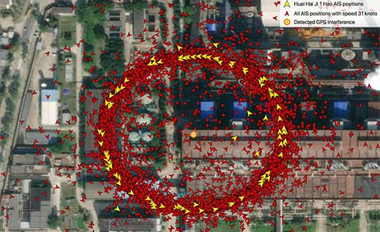
    “GPS spoofing circles” have been discovered at 20 locations along the Chinese coast, according to the non-profit environmental group Skytruth. Of the locations observed, 16 were oil terminals; the others were corporate and government offices. The spoofing in Shanghai resulted in reported positions from ships, fitness trackers and other GPS-enabled devices forming circles some distance from the shore — a phenomenon first observed by the non-profit C4ADS. Professor Todd Humphreys briefed the phenomena at an Institute of Navigation conference in September, and MIT Technology Review published an article about it in November 2019.

  • Finding time: Accuracy test of Locata Network takes place at White Sands

    Finding time: Accuracy test of Locata Network takes place at White Sands

    An accuracy test of the Locata Network — a non-GPS-based positioning system installed at the U.S. Air Force White Sands Missile Range in New Mexico — focused on timing down to the nanosecond, with impressive results.

    In 2018, the 746th Test Squadron (746 TS) tested its Non-GPS-Based Positioning System (NGBPS) at White Sands Missile Range as an alternative to GNSS for precise time transfer and synchronization. This was the first independently measured and characterized testing program for the NGBPS, which leverages Locata’s radio-based position, navigation and timing (PNT) technology to achieve high accuracy independent of GPS.

    Using specific parameters and equipment configurations, independent experts proved Locata’s absolute and relative time synchronization and frequency stability performance. Under testing, the NGBPS provided exceptional time transfer and frequency stability across large areas.

    With these successful results in hand, the U.S. Department of Defense will be able to leverage this capability for programs requiring high-precision time and frequency distribution, without relying on GPS alone. Plus, the system is flexible — Locata’s area of transmission can be increased to cover substantially larger areas than at White Sands for safety-of-life, military or government-mandated systems.

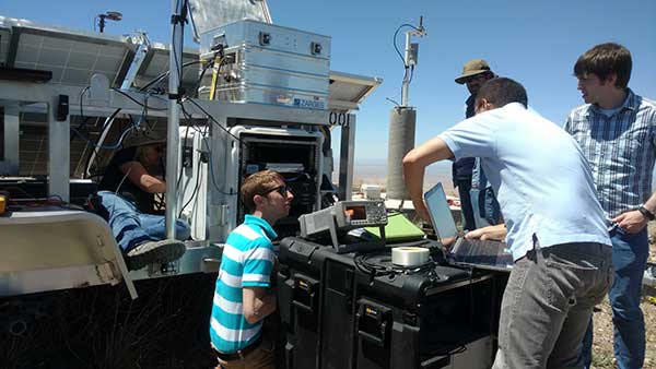
    With USNO personnel, members of the 746 TS reconfigure the Master LocataLite site for the test. (Photo: 746 TS/USAF)
    With USNO personnel, members of the 746 TS reconfigure the Master LocataLite site for the test. (Photo: 746 TS/USAF)

    Background

    Over the past two decades, the free availability of GPS time has enabled a plethora of time-dependent applications. Time and frequency synchronization between remote locations is crucial for digital communication systems, electrical power grids and financial networks, to name a few. Military operations also require accurate and reliable time information. Typically, these applications require accurate time synchronization ranging from 10 microseconds (μs) down to 100 nanoseconds (ns). Yet, while our critical reliance on GPS for time transfer continues to escalate, GPS remains susceptible to interference, disruption or denial.


    See also Automated shipping moves containers with Locata.


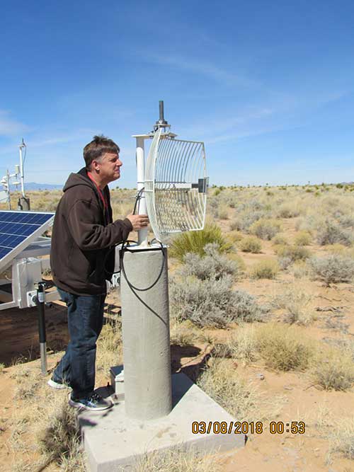
    A technician with the 746 TS re-aims a LocataLite antenna for an alternative TimeLoc configuration. (Photo: 746 TS/USAF)
    A technician with the 746 TS re-aims a LocataLite antenna for an alternative TimeLoc configuration. (Photo: 746 TS/USAF)

    Locata. Locata Corp., a privately owned Australian company with a U.S. subsidiary, invented a radio-location technology that provides precise PNT for environments where GPS coverage is unavailable. Locata ground-based PNT technology delivers positioning that, in many scenarios, far exceeds the performance and reliability of GPS. LocataNets, the company’s terrestrial networks, function as local ground-based replicas of traditional GPS position and timing services. They can be designed to reliably deliver a powerful, controllable, tailored signal as user applications require.

    A LocataNet consists of synchronized LocataLite transceivers, all-in-one units that transmit and receive out of the same 10 x 5 x 1-inch box. Cables are connected to antennas for signal reception and transmission. Locata Rovers are mobile receivers within the network that use these synchronized LocataLite signals to calculate an accurate PNT solution.

    The 746 TS employs the basic LocataNet laydown — multiple Slave LocataLites receive signals from a single Master LocataLite transceiver. The patented process by which slaves are synchronized to the master (or other slaves) is known as TimeLoc.

    Until these new tests were run, the squadron’s attention had primarily been focused on the high-accuracy use of Locata’s position and navigation solution as an alternative to GPS when it is jammed, deceived or unreliable. But because all LocataLites are precisely synchronized via TimeLoc, network synchronization is a natural extension of Locata technology’s core capabilities.

    In October 2015, GPS World reported that the United States Naval Observatory (USNO) showed LocataLites are a viable option for a stable 1 pulse per second (1 pps) distribution setup within an urban environment, where it can support applications such as cell-tower synchronization in GPS-challenged environments. The USNO tests demonstrated synchronization of less than 200 picoseconds — significantly better than any other known wireless network synchronization methodology, including GPS. If clear line-of-sight is available between a master and Slave LocataLite, precision is 50 picoseconds with frequency stability to 1×10-15 —better than a Stratum One atomic clock.

    Because of the USNO’s timing expertise and familiarity with Locata TimeLoc testing, the 746 TS tasked the USNO to conduct independent synchronization experiments at White Sands, with the following objectives:

    • Evaluate the Locata master, slaves and non-Locata timing receiver at the master site in reference to USNO master atomic clock time.
    • Determine the Locata network’s internal, independent synchronization stability and accuracy.
    • Determine the Locata Rover’s 1 pulse per second (PPS) time stability and accuracy, for use in time transfer applications.

    The primary purpose of the tests was to show that nanosecond-level time transfer is possible over significantly wide areas by using Locata, and that TimeLoc technology offers a relatively easy means of supporting exceptionally high-precision time and frequency distribution over large broadcast areas.

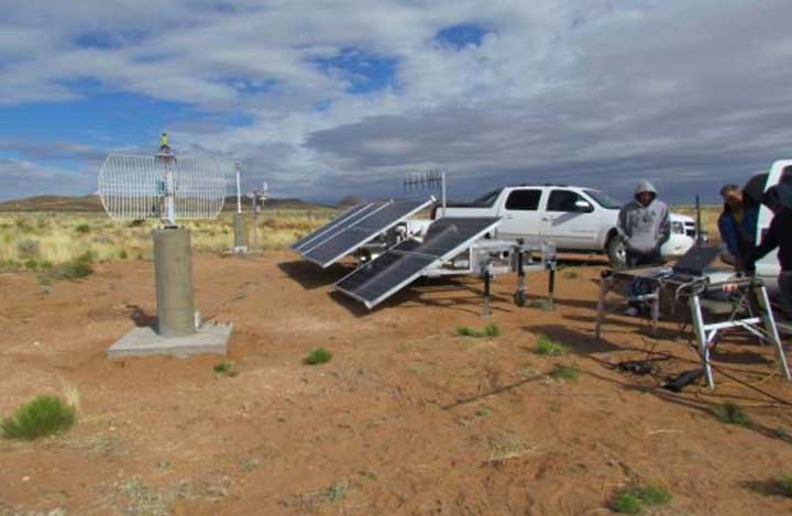
    Slave LocataLite site layout. (Photo: 746 TS/USAF)
    Slave LocataLite site layout. (Photo: 746 TS/USAF)

    Synchronization Method

    Since Locata technology was originally developed as an RF-based high-precision non-GPS-based positioning and navigation system, the time synchronization accuracy requirements for a LocataLite transceiver are very high. If centimeter positioning precision is desired for a Locata receiver, every small fraction of a second is significant; for instance, a 1-ns error in time equates to an error of approximately 30 centimeters (because of the speed of light).

    TimeLoc is a patented high-accuracy wireless synchronization method developed by Locata Corp. It allows LocataLites to achieve high levels of synchronization without atomic clocks, external control cables, differential corrections or a master reference receiver.

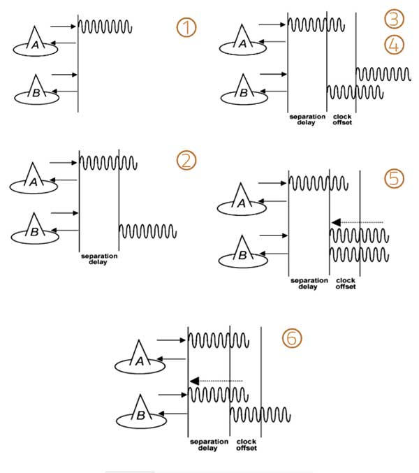
    The TimeLoc procedure is described in the following steps for synchronizing two LocataLites (see Figure 1).

    1. LocataLite A transmits a unique signal (code and carrier).
    2. The receiver section of LocataLite B acquires, tracks and measures the signal generated by LocataLite A.
    3. LocataLite B generates its own unique signal (code and carrier) which is transmitted, but, importantly, it is also received by the receiver section of LocataLite B.
    4. LocataLite B calculates the difference between the signal received from LocataLite A and its own locally generated and received unique signal. Ignoring propagation errors, the differences between the two signals are due to the clock difference between the two devices and the geometric separation between them.
    5. LocataLite B adjusts its local oscillator to bring the differences between its own signal and LocataLite A to zero. The signal differences are continually monitored and adjusted so that they remain zero. In other words, the local oscillator of B follows precisely that of A.
    6. The final stage is to correct for the geometrical offset (range) between LocataLite A and B, using the known coordinates of the LocataLites. When this step is accomplished, TimeLoc has been achieved.
    Figure 1. The TimeLoc process. (Image: Author)
    Figure 1. The TimeLoc process. (Image: Author)

    The only requirement for establishing a LocataNet using TimeLoc is that LocataLites must receive signals from one other LocataLite. However, received signals do not have to come from the same central or Master LocataLite, because this may not be possible in difficult environments or when propagating the LocataNet over large areas. Instead, a LocataNet can “cascade” TimeLoc through intermediate LocataLites. For example, if a third LocataLite C can only receive the signals from B and not Master LocataLite A, it can use B’s signals for time synchronization instead of A’s, provided that B has already TimeLoc’d to the network. Therefore, by using “cascaded TimeLoc,” there is theoretically no limit to the number of LocataLites that can be synchronized.

    Test item description

    The NGBPS at White Sands consists of an operational LocataNet, where each node (a site instrumented with a LocataLite) is synchronized via Locata’s patented TimeLoc technique. The LocataNet, combined with a mobile Rover, is a subsystem of the 746 TS Ultra-High-Accuracy Reference System (UHARS), which provides PNT information in GPS-denied environments. The NGBPS operates in the 2.4-GHz industrial, scientific and medical band, which is far enough away from GPS frequencies to be unaffected by GPS jamming. Although it is currently used as a source of position truth during GPS jamming, the 746 TS understands that the NGBPS is potentially a source of high-accuracy timing data as well.

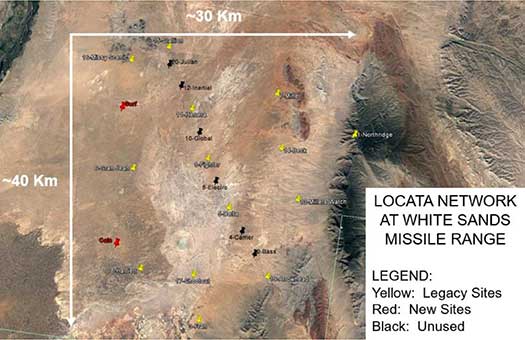
    The UHARS is in the northern portion of White Sands Missile Range. It typically consists of 16 LocataLite sites. The master site is at North Oscura Peak, or NOP (labeled Northridge in Figure 2); all other sites are time synchronized to that master site.

    Figure 2. Locata network at White Sands Missile Range. (Image: Author)
    Figure 2. Locata network at White Sands Missile Range. (Image: Author)

    Each LocataLite site consists of:

    • one LocaLite
    • two monuments—pillars for antenna placement (Note: The two new sites lack the permanent monuments for antenna placement)
    • two transmit antennas
    • one receive antenna
    • one meteorological station—for meteorological data
    • one communication antenna
    • one trailer for power and transport

    The communications antenna at each site is attached to a UHF modem that is used for 746 TS remote control of the LocataNet. This allows remote data logging, reconfiguration or monitoring of the network without having to drive to each site. However, it should be noted that no communications system whatsoever is required for the Locata NGBPS TimeLoc capability to run.

    To support the timing tests, the LocataNet was reconfigured several times to meet requirements of specific test objectives. These configurations are described below.

    Static ground tests

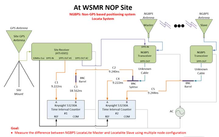
    Static ground tests involved multiple configurations. The first (Figure 3) consisted of two LocataLites (master and terminal slave) collocated at NOP close enough that their respective PPS outputs could be compared in a single time interval counter. A terminal Slave LocataLite was installed at NOP specifically for this test.

    Figure 3. LocataLite Configuration 1: North Oscura Peak (NOP) site test instrumentation. (Image: Author)
    Figure 3. LocataLite Configuration 1: North Oscura Peak (NOP) site test instrumentation. (Image: Author)

    This setup also facilitated simple network reconfiguration to change the number of LocataLite sites being tested. By programming LocataLites to TimeLoc to specific sites at White Sands and redirecting their respective antennas accordingly, the TimeLoc chain under test could be expanded to have multiple sites between the LocataLite master and the collocated terminal slave without changing measuring equipment instrumentation at NOP. This means that the time transfer could hop, or cascade, between one or more sites and be measured with the same test instrumentation.

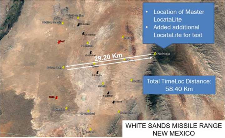
    Configuration 2 consisted of three LocataLites: The master at NOP, a slave at Gran-Jean and the terminal slave at NOP. Again, the master and terminal slave were collocated close enough to each other that their respective PPS outputs could be compared in a single time interval counter, but this time the network was configured to cascade the TimeLoc signal through the slave at Gran-Jean, 29.20 km away. Since the TimeLoc signal now had to cascade through two sites and travel from the master at NOP to Gran-Jean and back to the terminal slave at NOP, the effective TimeLoc travel distance was 58.40 km (Figure 4).

    Figure 4. LocataLite Configuration 2: Total TimeLoc distance is 58.40 km. (Image: Author)
    Figure 4. LocataLite Configuration 2: Total TimeLoc distance is 58.40 km. (Image: Author)

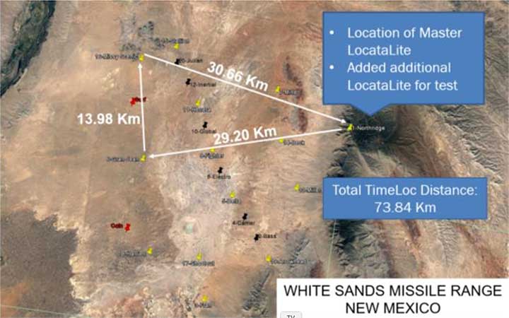
    Configuration 3 consisted of four LocataLites: The master at NOP, a slave at Gran-Jean, a slave at Missy-Scenic and the terminal slave at NOP. This configuration forced the TimeLoc signal to cascade through three sites and travel a total distance of 73.84 km (Figure 5).

    Figure 5. LocataLite Configuration 3: Total TimeLoc distance is 73.84 km. (Image: Author)
    Figure 5. LocataLite Configuration 3: Total TimeLoc distance is 73.84 km. (Image: Author)

    Ground vehicle test

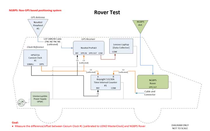
    For Configuration 4, a Locata Rover was instrumented on the squadron’s Small Test Vehicle (STV), which drove all accessible roads within the LocataNet’s coverage (Figure 6). During this mobile test, the LocataNet was configured with 10 active LocataLites. The Locata Rover in the vehicle used Locata signals from available nodes to calculate Locata network time, which was synchronized to the GPS timing receiver at NOP. The data collected determined how well network time is synchronized while in a moving vehicle.

    Figure 6. Rover test installation on Small Test Vehicle. (Image: Author)
    Figure 6. Rover test installation on Small Test Vehicle. (Image: Author)

    Test results

    To collect the required data, USNO first had to characterize the performance of the master site’s GPS timing receiver at NOP, and then synchronize it to two separate USNO atomic clocks that could be used as remote timing references for the tests. The GPS timing receiver is equipped with a rubidium oscillator, which produces a GPS-disciplined 1 pps output signal. Its internal rubidium clock is a stable source of time with an advertised UTC (USNO) offset of a best case 15-ns root mean square (RMS) and a worst case 100-ns RMS.

    The cesium clocks output 5- or 10-MHz sinusoids and a 1 pps signal. The cesium clocks output 5- or 10-MHz sinusoids and a 1 pps signal and were characterized relative to the USNO correction receiver, which USNO personnel had characterized relative to UTC. Correction data available from a time interval counter could then be applied to tie the timing receiver back to USNO time. The measurements at NOP recorded the difference between the timing receiver and the cesium clocks. Using the relationship between the cesium clocks and UTC (USNO), one could characterize the timing receiver’s time relative to USNO time.

    The USNO calibrated measurements at the nanosecond level using two methodologies. The most common approach was simply to compare two 1 pps signals, a method known as “tick-tick.” Another important methodology is referred to as a “tick-phase,” which is a measurement of a sinusoidal signal compared to a 1 pps reference. Some timing equipment will have discrete time jumps with certain tick-phase measurements, because of how narrow the distance between the rising edges of a sine wave is compared to a 1 pps signal.

    There’s a chance that the 1 pps signal is close to two rising edges of a sine wave, causing the signal to jump back and forth in its timing measurement, depending on which rising edge of the sine wave it uses.

    Measurements were further complicated by the delicate nature of cesium clocks, which perform best under finely controlled laboratory conditions. Each cesium reference exhibits its own characteristics that must be observed, measured, and accounted for. Moreover, transporting them to White Sands Missile Range for this test where temperature fluctuations, moving vehicle vibrations, and altitude variations among devices were introduced made synchronization of these clocks particularly challenging. For example, USNO discovered that the Cesium Clock #1 had its internal batteries disconnected — possibly through the original shipment to White Sands, the constant vehicle vibrations while driving on the range, a faulty wiring in the battery terminals, or possibly a combination of all. This problem induced a random offset in the clock, and calibration had to be re-accomplished to reestablish traceability back to UTC (USNO).

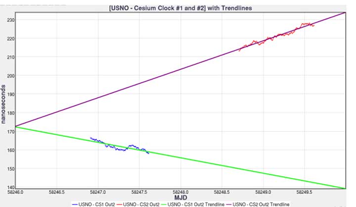
    Figure 7 shows each cesium clock’s measured drift rate in nanoseconds/second and its corresponding linear fit. This trendline can then be used to project cesium clock #2 to the past and compare it to the measurements of cesium clock #1.

    Figure 7. USNO cesium clocks with trendlines. (Image: Author)
    Figure 7. USNO cesium clocks with trendlines. (Image: Author)

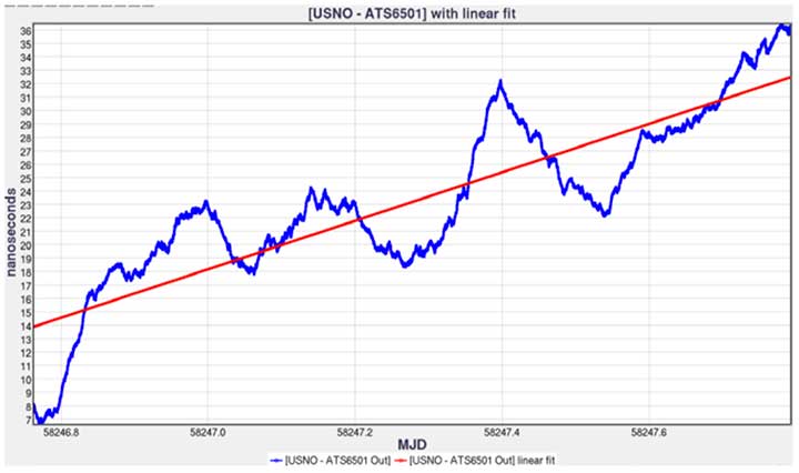
    Figure 8 shows the relationship between the timing receiver and USNO master clock and its linear fit. Performing linear fit approximations of the cesium clocks likely introduced unknown errors, potentially increasing the variance of the 1 pps differences.

    Figure 8. USNO versus timing receiver with linear fit. (Image: Author)
    Figure 8. USNO versus timing receiver with linear fit. (Image: Author)

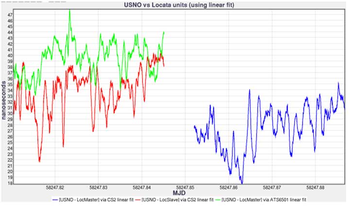
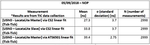
    Comparing the 1 pps outputs of the LocataLite master and collocated LocataLite slave to the master site reference clocks (CS2 or timing receiver 1 pps out), the data is traceable back to USNO using the linear fits found for both the USNO timing receiver and cesium clock #2 (Figure 9).

    Figure 9. USNO compared to Locata system for May 9, 2018, time interval counter measurements. (Image: Author)
    Figure 9. USNO compared to Locata system for May 9, 2018, time interval counter measurements. (Image: Author)

    LocataLite timing measurement bias was within 40 ns, and the stability was within 3.7 ns of the reference clocks (see Table 1). The stability of the system is encouraging, as the mean offset can be driven down by more precise measurements and more precise calibrations such as using a two-way satellite time-transfer calibration method (TWSTT).

    Table 1. USNO compared to Locata system tabulated values and statistics. (Image: Author)
    Table 1. USNO compared to Locata system tabulated values and statistics. (Image: Author)

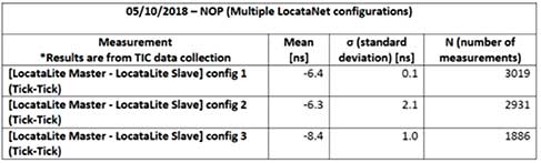
    In Table 2, we compare measured data of the 1 pps outputs of the LocataLite master to the collocated LocataLite slave and compute the Locata network internal synchronization in each of the network configurations tested. The data reveals that the network synchronization accuracy is ≤ 2.1 ns. Unfortunately, during Configuration 2 testing, which propagated the TimeLoc signal from NOP to Gran-Jean and back (a total distance of 58.40 km), a technician inadvertently obstructed line-of-site between Locata antennas and consequently temporarily disturbed TimeLoc. Those data points were not removed before this analysis, which is why the reported standard deviation in that configuration, although quite good at 2.1 ns, is nevertheless uncharacteristically high.

    Table 2. LocataNet internal synchronization. (Image: Author)
    Table 2. LocataNet internal synchronization. (Image: Author)

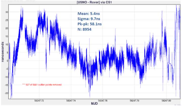
    Finally, Figure 10 shows the timing measurements between the USNO master clock and the mobile Locata Rover, via the cesium clock #1 linear fit. Unlike in the LocataLite tests, the Rover is not TimeLoc’d to the network. Instead, it simply calculates its time from LocataLite signals within its line of sight, similar to how a GPS device will calculate its time from satellite signals. During this test, the Rover’s calculated timing accuracy showed a mean of 5.4 ns and stability within 9.7 ns of the USNO master clock, while driving all over the northern portion of the range. To produce the plot, 927 outliers were removed (3 sigma). The outliers occurred at the beginning and ending of the test, when the vehicle was moving from its parking location at Stallion Range Center (outside the operational LocataNet) to the test route and back. The buildings in the area obstructed line of sight and induced significant multipath, which degraded the Rover’s calculations.

    Figure 10. USNO LocataLite Rover via CS1 linear fit. (Image: Author)
    Figure 10. USNO LocataLite Rover via CS1 linear fit. (Image: Author)

    Conclusion

    This endeavor for USNO to characterize the 746 TS NGBPS was met with many challenges, which emphasize the real-world difficulty of measuring time at these extremely fine levels in the field using atomic clocks. The USNO found that some non-linearity started occurring in the USNO – Cesium Clock #2 measurements because of the container of Cesium Clock #2 not being ideal for temperature stability. They also discovered that Cesium Clock #1 had its internal batteries disconnected due to an unknown cause. However, because of deliberate measurements between Cesium Clock #1 and Cesium Clock #2, the USNO was still able to provide calibration measurements but with degradation in the measurement clarity.

    From the data collected, USNO personnel found:

    1. The GPS timing receiver at NOP produced 1 pps timing accuracy consistent with its 15-ns RMS specification. Therefore, the reference time delivered to the Master LocataLite was synchronized to UTC within 15 ns.
    2. A standard deviation measurement from Master LocataLite to UTC of under 4 ns.
    3. Locata’s master-to-slave internal time synchronization (independent of GPS) was measured to be between 100 ps and 2.1 ns in 3 different Locata network configurations spanning distances up to 73.84 km (45.88 miles).
    4. The timing measurements in the mobile Rover test show its ability to provide accurate time with a standard deviation of around 10 ns.

    Many lessons learned throughout this experiment could be implemented to get more accurate measurements, especially when looking at the accuracies of the GPS time transfer throughout the NGBPS. Looking ahead, more accurate calibration values for both the GPS timing receiver and the Master LocataLite could be made by using a TWSTT method. This would simplify the number of measurements and provide a 1 pps signal of USNO’s master clock, resulting in up to 1 ns of accuracy in the reference time delivered to the Master LocataLite. Depending on the requirements of customers needing NGBPS time at White Sands, the 746 TS and USNO can potentially recharacterize the NGBPS timing accuracy and stability using this methodology.

    Manufacturers

    The LocataLites and Rovers that create much of the 746 TS NGBPS are manufactured by Locata Corp. The NGBPS synchronized to GPS time via a Microsemi ATS6501 timing receiver. The cesium clocks were Hewlett-Packard 5071A cesium primary frequency standard devices. The USNO used a Novatel ProPak3 for correction data, measured using a Keysight 53230A time interval counter.


    Christopher Black earned a B.S. and M.S. in electrical and computer engineering from New Mexico State University. In November 2017 he joined the 746th Test Squadron, Holloman Air Force Base, as a navigation warfare analyst. Now, as lead reference engineer, he heads up research, development and maintenance of the squadron’s reference systems, including UHARS.

    This article has been approved by the USAF for public release, #AEDC2019-205.