Category: Applications

  • U.S. Air Force chooses Collins Aerospace GPS anti-jam receiver

    U.S. Air Force chooses Collins Aerospace GPS anti-jam receiver

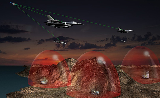
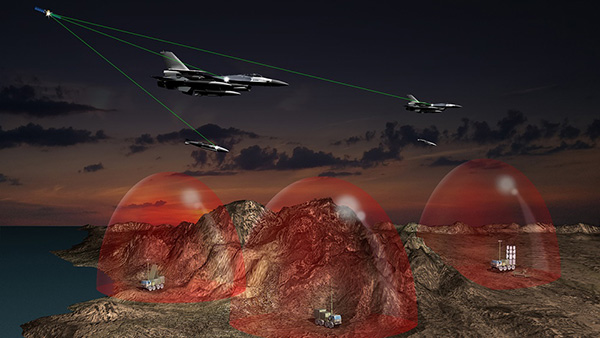
    The U.S. Air Force has selected an anti-jam GPS receiver from Collins Aerospace (through the division formerly known as Rockwell Collins) for Air National Guard and Air Force Reserve F-16 fighter aircraft.

    The U.S. Air Force Life Cycle Management Center (USAF AFLCMC) chose Collins Aerospace to supply its latest-generation Digital GPS Anti-Jam Receiver (DIGAR), designed to prevent jamming of GPS signals.

    The DIGAR receivers will provide highly reliable navigation for U.S. Air National Guard and U.S. Air Force Reserve F-16 aircraft operating in contested, electromagnetic environments.

    This will be the first combat fighter aircraft to be installed with the latest version of the receiver.

    “As enemies continue to find new ways to affect the ability to navigate, the latest DIGAR will provide the highest level of protection available so our warfighters can execute missions with precision and accuracy,” said Troy Brunk, vice president and general manager, Communication, Navigation & Electronic Warfare Solutions for Collins Aerospace.

    Image: Rockwell Collins
    Image: Collins Aerospace

    Integration of the DIGAR requires no changes to existing operational flight programs or A-kit aircraft wiring, lowering the risk and cost involved to upgrade.

    Built on an open systems architecture, the DIGAR is designed for use across a variety of aircraft platforms that include rotary wing, fixed-wing fighter, bomber, transport aircraft and small to large unmanned aerial systems.

    DIGAR is a form, fit replacement for existing antenna electronic systems with demonstrated performance that exceeds legacy capability, the company said.

    DIGAR Features

    • Superior digital beamforming or nulling anti-jam
    • Up to 16 simultaneous beams for superior jamming immunity to 125+ dB J/S performance (beamsteering mode, actual performance is classified.)
    • Two- to seven-element CRPA compatible
    • Simultaneous L1/L2 protection
    • Supports Y-code and M-code Anti-jam
    • Supports STAP/SFAP beamforming
    • Two form factors: DIGAR-200 (218 cubic inches) or DIGAR-300 (75 cubic inches)
    • Supports retrofit AE-1/GAS-1/ADAP platforms


  • Port of Amsterdam trials GPS-based UAV monitoring system

    The M.A.D.S. radomes track drones at the port, so they can be identified as beneficial or a threat. (Photo: Martek)
    The M.A.D.S. radomes track drones at the port, so they can be identified as beneficial or a threat. (Photo: Martek)

    The Port of Amsterdam has begun a four-week trial of a drone detection system. Martek Anti-Drone Systems is providing its M.A.D.S. (Marine Anti-Drone System) to build understanding of how, where and why drones are flying over the Port of Amsterdam.

    The M.A.D.S system will support the port by monitoring legal and illegal flying across its land. The system detects and identifies drones within a 5-kilometer range, providing GPS positioning of both drone and pilot together with the drone’s speed and heading.

    Configurable and escalating stage alarms in real time allow the drones’ intentions to be assessed in time to decide on appropriate defense actions.

    M.A.D.S. radomes are installed around the Port of Amsterdam. (Photo: Martek)
    M.A.D.S. radomes are installed around the Port of Amsterdam. (Photo: Martek)

    The data collected from the trial will have far-reaching influence on the future use of UAVs (unmanned aerial vehicles) across the 650-hectare port area, according to Martek.

    The port has identified the potential of drones for numerous use applications across its operations and its customers’ operations. Many port customers are preparing to use drones for infrastructure inspection and measurement of environmental parameters. The trial will monitor their use.

    Project manager of  innovation Joost Zuidema is overseeing the trial for the Port Authority. “This trial is an important part of our innovation strategy,” Zuidema said. “The M.A.D.S system gives us a first opportunity to get a feeling for the technology that will help us understand drone usage and make a first assessment on unwanted drone flights in a part of our port.”

    Like any tool, drones are being used for good as well as malevolent purposes. There is a potential threat to transport such as container ships and major infrastructure, such as ports, around the world. Threats include:

    • privacy invasion
    • terrorism threats of explosives or gas attack
    • flyby hacking to take control of autonomous or semi-autonomous systems
    • stealing valuable data off unprotected networks or breaking into insecure networks
    Infographic: Martek:
    Infographic: Martek:

    “As the Port Authority, we do want ensure drone flights in our port are carried out safely and responsibly, within the laws and regulations,” Zuidema said.

    “The growing trend for the use of UAVs being used on ports, commercial shipping and super yachts is, as yet, not fully recognised by authorities,” said Erik Van Wilsum, Martek. “We are delighted to be working with Port of Amsterdam, who are on the cutting edge of developing technology to understand the opportunities for drone use and the potential threats and benefits they can provide for key national infrastructure.”

    A report by International Data Corporation stated that it expected worldwide investment in drones to be US$12.3 billion in 2019, with drone purchase growing nearly twice as fast as the investment in robotics over the same period.

  • GPS to get terrestrial backup system

    GPS to get terrestrial backup system

    On Dec. 4, President Trump signed the Frank LoBiondo U.S. Coast Guard Authorization Act of 2018. Included in that bill was the National Timing Security and Resilience Act of 2018.

    The act tasks the Secretary of Transportation with establishing a terrestrial backup timing system for GPS within two years.

    Further, the bill ensures the availability of uncorrupted and non-degraded timing signals for military and civilian users in the event that GPS signals are corrupted, degraded, unreliable, or otherwise unavailable.

    The law requires that, to the maximum extent possible, the backup system be:

    • terrestrial
    • wireless
    • synchronized to UTC
    • difficult to disrupt
    • able to penetrate underground and inside buildings
    • capable of deployment to remote locations
    • expandable to provide position, navigation and timing (PNT), and
    • able to work in concert with similar systems such as eLoran.

    It also has provisions for the government to be able to establish the system through a commercial entity should it elect to do so. In such a case, it establishes several provisions that such a contract must meet.

    Image: @SENTEDCRUZ
    Image: @SENTEDCRUZ

    Timing a critical area. Timing has been an area of increasing focus and concern for both industry and government.

    The U.S. Alliance for Telecommunications Industry Solutions (ATIS), the standards body for the wireless industry, has cited GPS timing as a point of failure for wireless systems. Last year ATIS wrote to key senators, encouraging them to establish an eLoran system to provide a second and much more resilient timing source for America.

    In 2015 and 2016, the U.S. National Institutes of Standards and Technology issued reports that said America’s timing infrastructure was insufficient to support the growing internet of things (IOT).

    The bill was sponsored by a broad coalition in the House led by Congressmen John Garamendi (D-CA) and Duncan Hunter (R-CA). Senators Ted Cruz (R-TX) and Ed Markey (D-MA) led the effort in the Senate, where the bill passed with an overwhelming majority.

    U.S. Sens. Ted Cruz (R-Texas) and Ed Markey (D-Mass.) issued the following statements. “Establishing a reliable alternative timing system to GPS satellites is crucial to the national and economic security of the United States,” Sen. Cruz said. “If the current system were disrupted for even just a few hours, there would be an immediate threat to the American people, the economy, and our very way of life. Thankfully, Congress recognized the importance of addressing this issue. I am grateful for Sen. Markey’s leadership, and commend President Trump for signing this bill into law.”

    “The nation’s banking, communications, electricity, and transportation sectors rely on the precise timing provided by GPS,” Sen. Markey said. “We cannot allow this vital system to be imperiled by natural phenomenon like solar flares or coordinated attacks like jamming. I am so proud that President Trump has signed this important bill into law, and I thank for Senator Cruz for partnering on policy that will enhance the resilience and reliability of this critical infrastructure.”

    Defense attempt. Similar legislation that would have placed the responsibility for a terrestrial GPS backup system with the Department of Defense was introduced in 2015. While this was done with the acquiescence of senior DOD leadership, when the department later determined it did not want the responsibility, the measure failed.

    While this new law is not a funding bill, Congress provided $10M for a technology demonstration in 2018. Also, having a law in place requiring the system paves the way for funding in future appropriations bills.

  • Rohde & Schwarz and Huawei conduct field trials for 5G and V2X precision

    Rohde & Schwarz and Huawei conduct field trials for 5G and V2X precision

    Rohde & Schwarz and Huawei have successfully conducted cellular-based 5G V2X latency measurements in vehicular environments in field tests in Munich and Shanghai.

    In a joint project between Huawei and Rohde & Schwarz, a precision end-to-end delay measurement system for over-the-air IP transmissions was applied to 5G V2X communication for cooperative driving applications in field tests in a moving car.

    The precision absolute time standards on both ends were derived from two independent GPS receivers.

    URLLC will enable automated driving. (Image: Rohde & Schwarz)
    URLLC will enable automated driving. (Image: Rohde & Schwarz)

    The initial measurements show that it is possible to achieve delays in the millisecond regime in a 5G network, demonstrating superior latency performance in comparison to LTE.

    One of the key use cases of 5G is ultra-reliable low-latency communication (URLLC). Important for advanced vehicle-to-X communication use cases, URLLC will enable automated driving in the future.

    A measurement accuracy below 2 µs for each transmitted IP packet was demonstrated. The transmitted data contained various IP traffic streams including video, lidar and control data (ITS messages) for a tele-operated vehicle.

    While the trial in Munich was related to a tele-operated driving project, the tests in Shanghai were related to a platoon V2X testing site, where a number of vehicles traveling together are electronically connected via wireless communication.

    The delay for transmission of one IP packet from source over-the-air to a (moving) receiver (sink) needs to be measured, spanning all delays introduced by the radio transmitter, propagation delay and radio receiver from/to IP packet level.

    As latency is one of the key performance indicators of 5G and crucial for safety applications, such measurements could become an important criterion for future certification testing.

    “We are delighted to collaborate with Huawei to contribute with our test and measurement expertise to 5G technology development,” said Andreas Pauly, executive vice president,  Test & Measurement at Rohde & Schwarz. “With a strong global footprint in the telco ecosystem and close cooperation with partners, Rohde & Schwarz is committed to further expanding our innovative test and measurement solutions to new automotive applications.”

  • Audi, Airbus and Italdesign test flying taxi concept

    Audi, Airbus and Italdesign test flying taxi concept

    Audi, Airbus and Italdesign presented for the first time a flying and driving prototype of Pop.Up Next, a flying taxi. The companies demonstrated the concept at Drone Week, held Nov. 27-29 in Amsterdam.

    The concept combines a self-driving electric car with a passenger drone. In the first public test flight, the flight module accurately placed a passenger capsule on the ground module, which then drove from the test grounds autonomously.

    Photo: Audi
    Photo: Audi

    The demonstration was done with a 1:4 scale model. But as soon as the coming decade, Audi customers could use the flying taxi service in large cities — in multi-modal operation, in the air and on the road, without changing vehicles.

    “Flying taxis are on the way. We at Audi are convinced of that,” said Bernd Martens, Audi board member for sourcing and IT and president of the Audi subsidiary Italdesign. “More and more people are moving to cities. And more and more people will be mobile thanks to automation. In future senior citizens, children, and people without a driver’s license will want to use convenient robot taxis. If we succeed in making a smart allocation of traffic between roads and airspace, people and cities can benefit in equal measure.”

    To see what an on-demand service of this kind could be like, Audi is conducting tests in South America in cooperation with the Airbus subsidiary Voom. Customers book helicopter flights in Mexico City or Sao Paulo, while an Audi is at the ready for the journey to or from the landing site.

    “Services like this help us to understand our customers’ needs better,” Martens said. “Because in the future, flying taxis will appeal to a wide range of city dwellers. With Pop.Up Next we are simultaneously exploring the boundaries of what is technically possible. The next step is for a full-size prototype to fly and drive.”

    Audi is also supporting the Urban Air Mobility flying taxi project in Ingolstadt. This initiative is preparing test operations for a flying taxi at Audi’s site, and is part of a joint project of the European Union in the framework of the marketplace for the European Innovation Partnership on Smart Cities and Communities.

    The project aims to convince the public of the benefits of the new technology and answer questions concerning battery technology, regulation, certification and infrastructure.

  • Rolls-Royce and Finferries demonstrate fully autonomous ferry

    Rolls-Royce and Finnish state-owned ferry operator Finferries have successfully demonstrated a fully autonomous ferry in the archipelago south of the city of Turku, Finland.

    The car ferry Falco used a combination of Rolls-Royce Ship Intelligence technologies to successfully navigate autonomously during its voyage between Parainen and Nauvo. The return journey was conducted under remote control.

    Finnish ferry Falco uses Rolls-Royce ship intelligence to dock. (Photo: Rolls-Royce)
    Finnish ferry Falco uses Rolls-Royce ship intelligence to dock. (Photo: Rolls-Royce)

    During the demonstration, the Falco, with 80 invited VIP guests aboard, conducted the voyage under fully autonomous control. The vessel detected objects utilizing sensor fusion and artificial intelligence and conducted collision avoidance. It also demonstrated automatic berthing with a recently developed autonomous navigation system. All this was achieved without any human intervention from the crew.

    The Falco is equipped with a range of advanced sensors which allows it to build a detailed picture of its surroundings in real time. The situational awareness picture is created by fusing sensor data and it is relayed to Finferries’ remote operating centre on land, some 50 kilometres away in Turku city centre. Here, a captain monitors the autonomous operations, and can take control of the vessel if necessary.

    During the autonomous operation tests in Turku archipelago, Rolls-Royce has so far clocked close to 400 hours of sea trials. The Rolls-Royce Autodocking system is among the technologies that have been successfully tested. This feature enables the vessel to automatically alter course and speed when approaching the quay and carry out automatic docking without human intervention. During the sea trials, the collision avoidance solution has also been tested in various conditions for several hours of operation.

    Earlier this year Rolls-Royce and Finferries began collaborating on a new research project called SVAN (Safer Vessel with Autonomous Navigation), to continue implementing the findings from the earlier Advanced Autonomous Waterborne Applications (AAWA) research project, funded by Business Finland.

    “Today marks a huge step forward in the journey towards autonomous shipping and reaffirms exactly what we have been saying for several years, that autonomous shipping will happen,” said Mikael Makinen, president – Commercial Marine at Rolls-Royce. “The SVAN project has been a successful collaboration between Rolls-Royce and Finferries and an ideal opportunity to showcase to the world how Ship Intelligence technology can bring great benefits in the safe and efficient operation of ships.

    “This is a very proud moment for all of us and marks our most significant milestone so far. Today’s demonstration proves that the autonomous ship is not just a concept, but something that will transform shipping as we know it.”

    “We are very proud that maritime history has been made on the Parainen-Nauvo-route once again,” added Mats Rosin, Finferries’ CEO. “First with our world-renowned hybrid vessel Elektra and now Falco as the world’s first autonomous ferry. As a modern ship-owner, our main goal in this cooperation has been on increasing safety in marine traffic as this is beneficial for both the environment and our passengers. But we are also equally excited about how this demonstration opens the door to the new possibilities of autonomous shipping and safety.”

    The Falco is a 53.8 metre double-ended car ferry, which entered service with Finferries in 1993. It is equipped with twin azimuth thrusters from Rolls-Royce.

  • A look at NGS’ experimental and hybrid geoid models

    A look at NGS’ experimental and hybrid geoid models

    On Aug. 10, the National Geodetic Survey (NGS) released its latest experimental geoid model, xGeoid18. In early 2019, NGS is scheduled to release its next hybrid geoid model, Geoid18.

    NGS’ 2018 experimental geoid model, xGeoid18, and the next hybrid geoid model, Geoid18, are not the same. This column will address the latest experimental geoid model, xGeoid18, and the future hybrid geoid model, Geoid18, and why it’s important to understand that they are very different and cannot be interchanged.

    In my October 2015 column, I described the differences between NGS’ hybrid geoid models and their experimental geoid models. It has been three years since I wrote the newsletter that addressed the differences between the experimental geoid model and hybrid geoid models. NAPGD2022 is now only about three years away. There will be significant differences between NAVD 88 and NAPGD2022 height.

    My June 2017 column provided an estimate of the differences based on the 2016 experimental geoid model, xGeoid16b. These differences between NAVD 88 and NAPGD2022 will vary from state to state, as well as within an individual State. Products referenced to NAVD 88 will be different from products referenced to NAPGD2022. Users will need to prepare for the NAPGD2022 and develop implementation plans. Users should obtain an understanding of the differences between NAPGD2022 and NAVD 88.

    NGS has a webpage that provides information on all of their experimental geoid models. It page provides information on the development of the program and information on each of the experimental geoid models.

    NGS’ Experimental Geoid Website

    Photo: National Geodetic Survey Photo: National Geodetic Survey. Click to enlarge.

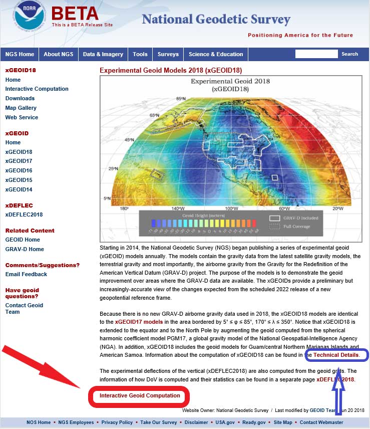
    If the user clicks on the xGeoid18 button (see orange arrow in the box titled “NGS’ Experimental Geoid Web Site”), the experimental geoid model xGeoid18 web page appears (see box titled “NGS’ Experimental Geoid Models 2018 Web Site”).

    NGS’ Experimental Geoid Models 2018 Website

    Photo: National Geodetic Survey

    Once users get to the xGeoid18 web site, they can obtain estimates of xGeoid18 values for any latitude and longitude by clicking on the button titled “Interactive Geoid Computation.” See red arrow in box titled “NGS’ Experimental Geoid Models 2018 Web Site.”

    Input Page of xGeoid18 Interactive Web Page Using the Sample Dataset
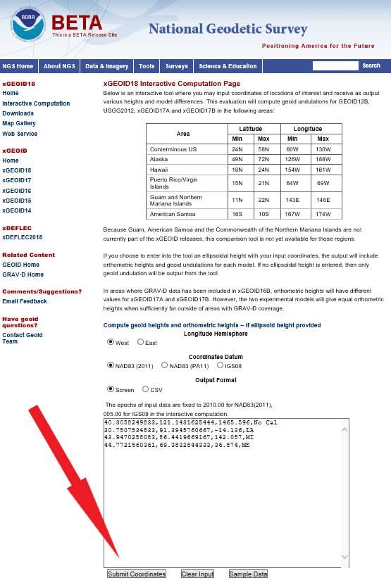
    Photo: National Geodetic Survey

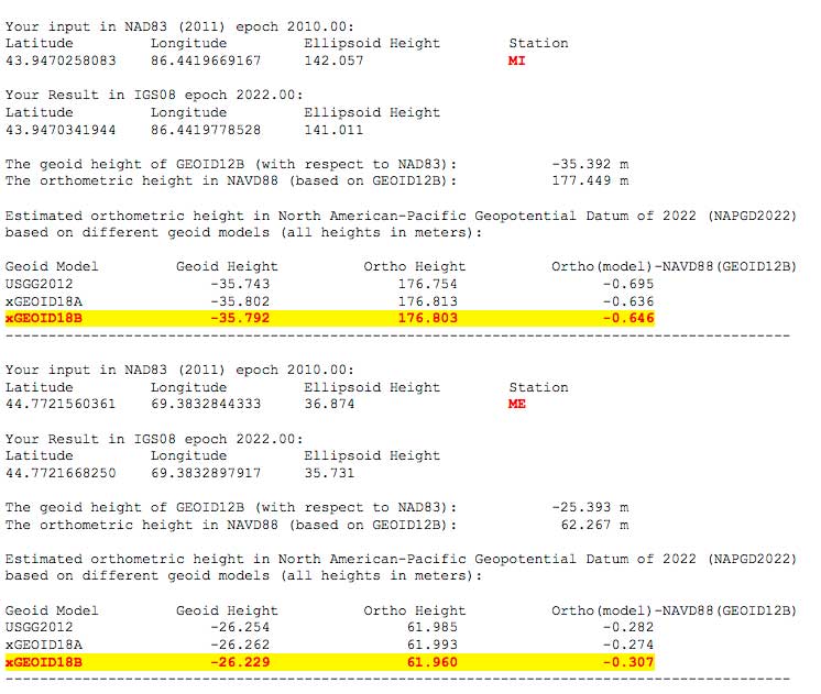
    Users should note that the output of the xGeoid18 interactive web service provides the results in IGS08 epoch 2022.00. The output provides an estimate of the NAVD 88 orthometric height based on GEOID12B, an estimate of the NAPGD2022 orthometric height based on xGeoid18b, and the difference between NAPGD2022 and NAVD 88. The box titled “Output from xGeoid18 Interactive Web Page Using the Sample Dataset” shows the output from the interactive web service using the sample dataset provided by the web service.

    The sample dataset has four stations — a station in California, Louisiana, Michigan and Maine. The results indicate that the differences will vary from state to state — the difference between NAPGD2022 and NAVD 88 in California using xGeoid18b is -0.722 meters, in Louisiana the difference is -0.274 meters, in Michigan the difference is -0.646 meters, and in Maine the difference is -0.307 meters (see box titled “Output from xGeoid18 Interactive Website Using the Sample Dataset”). More detailed estimates of differences between NAPGD2022 and NAVD 88 based on xGeoid16b can be found in my June 2017 column.

    Output from xGeoid18 Interactive Website Using the Sample Dataset

    Note: The GRS80 ellipsoid is used for both NAD83 and IGS08.

    Data: National Geodetic Survey

    Data: National Geodetic Survey

    Users can find technical information on xGeoid18 by clicking on the link labeled as Technical Details on the xGeoid18 website (see blue arrow in box titled “NGS’ Experimental Geoid Models 2018 Web Site”). The box titled “Excerpt from Technical Details for xGEOID18 Models” provides an excerpt of the technical details of xGeoid18.

    Excerpt from Technical Details for xGEOID18 Models

    Summary
    xGEOID18 is identical to xGEOID17 in the area bordered by 5˚ ≤ φ ≤ 85˚, 170˚ ≤ λ ≤ 350˚, which includes CONUS, Alaska, Hawaii, and Puerto Rico. Therefore, for information on xGEOID18 in those areas, the user should refer to the Technical Details of xGEOID17.

    For extended areas down to the equator and above latitude 85˚ north, the geoid is computed from the NGA’s Preliminary Geopotential Model 2017 (PGM17).

    The geoid models for Guam/central Northern Marianas Islands and American Samoa are computed in the closest way as xGEOID17 using the shipborne gravity, altimetric gravity and the reference gravity model PGM17.

    The deflections of the vertical are computed from all the geoid grids and the plumb curvature correction is applied by using the classical Bouguer reduction.


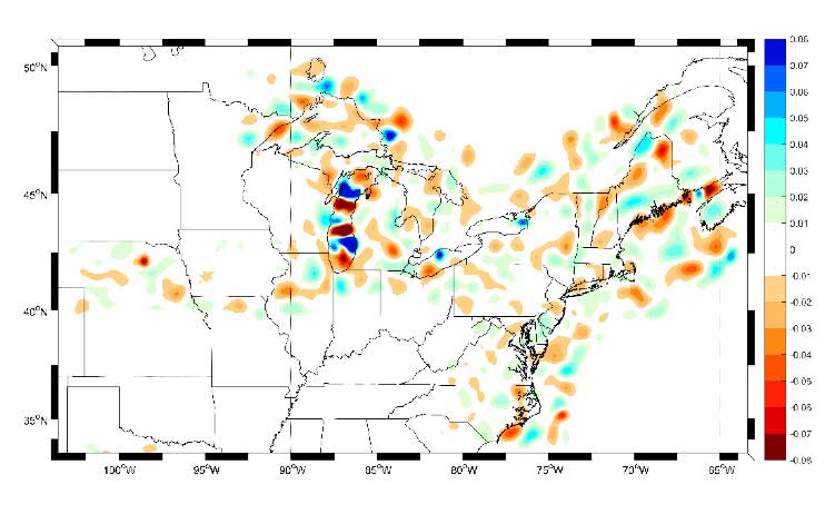
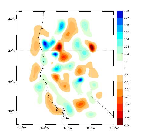
    As the technical detail webpage states, xGEOID18 is identical to xGEOID17 in the area bordered by 5˚ ≤ φ ≤ 85˚, 170˚ ≤ λ ≤ 350˚, which includes CONUS, Alaska, Hawaii and Puerto Rico. Therefore, for information on xGEOID18 in those areas, the user should refer to the Technical Details of xGEOID17. The box titled “Excerpt from Technical Details for xGEOID17 Models” provides an excerpt of the technical details of xGeoid17. This link provides figures that show the contribution of the airborne gravity data to the geoid models. See boxes titled “Excerpt from Technical Details for xGEOID17 Models” and “Figure (2,3,4,5) from Technical Details for xGEOID17 Models.” As stated in the technical details, users can examine each of the regional plots to see where the incorporation of GRAV-D data has changed the values of the xGeoid17B model.

    Excerpt from Technical Details for xGEOID17 Models

    GRAV-D Airborne Gravity Contribution

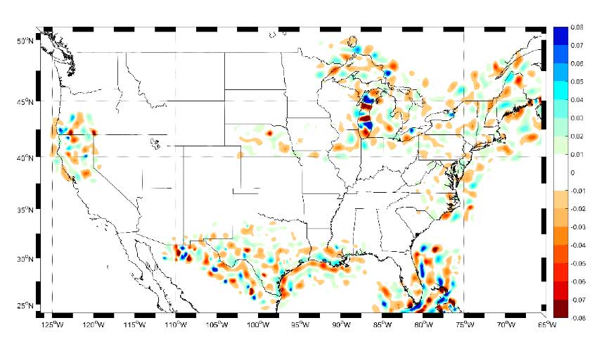
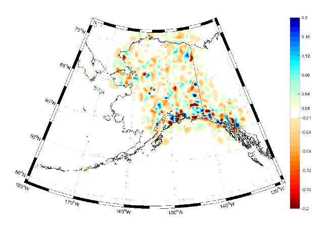
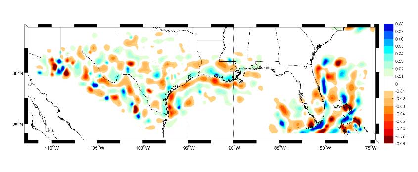
    The xGEOID17A and xGEOID17B models are identical except that xGEOID17B includes the available GRAV-D airborne gravity data. The difference between the two models shows the contribution of the airborne gravity data to the geoid models. Since the differences are only in areas where the GRAV-D airborne gravity data has been used, examining the regional plots given below will illustrate the varying levels of improvement due to GRAV-D, seen in different parts of the country.

    Photo: National Geodetic Survey

    Figure 1. CONUS – Contribution of GRAV-D airborne gravity [units in cm]

    Figure 2 from Technical Details for xGEOID17 Models

    Photo: National Geodetic Survey

    Figure 2. Alaska – Contribution of GRAV-D airborne gravity [units in cm]

    Figure 3 from Technical Details for xGEOID17 Models

    Photo: National Geodetic Survey

    Figure 3. Gulf Coast – Contribution of GRAV-D airborne gravity [units in cm]

    Figure 4 from Technical Details for xGEOID17 Models

    Photo: National Geodetic Survey

    Figure 4. Northeast – Contribution of GRAV-D airborne gravity [units in cm]

    Figure 5 from Technical Details for xGEOID17 Models

    Photo: National Geodetic Survey

    Figure 5. Pacific Coast – Contribution of GRAV-D airborne gravity [units in cm]

    What does mean to a user today? A station can now have a published ellipsoid height, modeled GEOID12B value, a published NAVD 88 orthometric height, and several xGeoid modeled values. This can lead to confusion if the user is not careful about providing the correct metadata associated with their data and results.

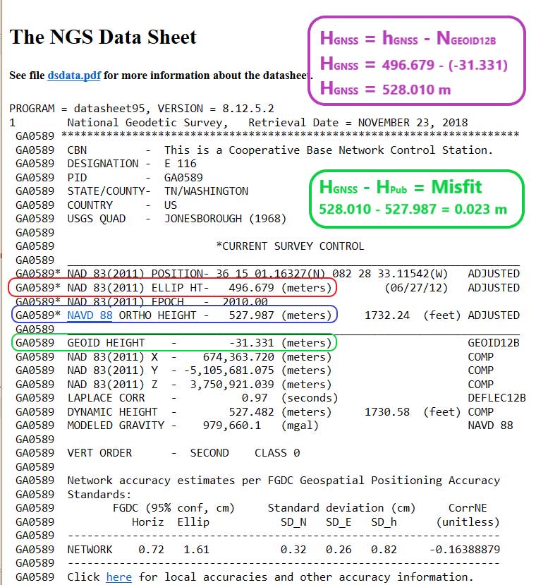
    The box titled “Excerpt from The NGS Data Sheet for Station E 116 (PID GA0589)” provides the output from NGS data sheet retrieval program. The first item to note is that if you compute the GNSS-derived orthometric height (HGNSS) using the formula:

    Equation: National Geodetic Survey Equation: National Geodetic Survey

    the computed value does not equal the published NAVD 88 leveling-derived orthometric height. In this example, the two heights differ by 2.3 cm. As explained in a previous column, GEOID12B is a hybrid geoid model that is distorted to be consistent with NAVD 88 published heights. It is a model and the documentation states that “The relative accuracy of GEOID12B to NAVD88 is characterized by a misfit of +/-1.7 centimeters nationwide.” The box titled “Excerpt from The NGS Data Sheet for Station E 116 (PID GA0589)” provides the computations and the results.

    Excerpt from The NGS Data Sheet for Station E 116 (PID GA0589)

    Data: National Geodetic Survey

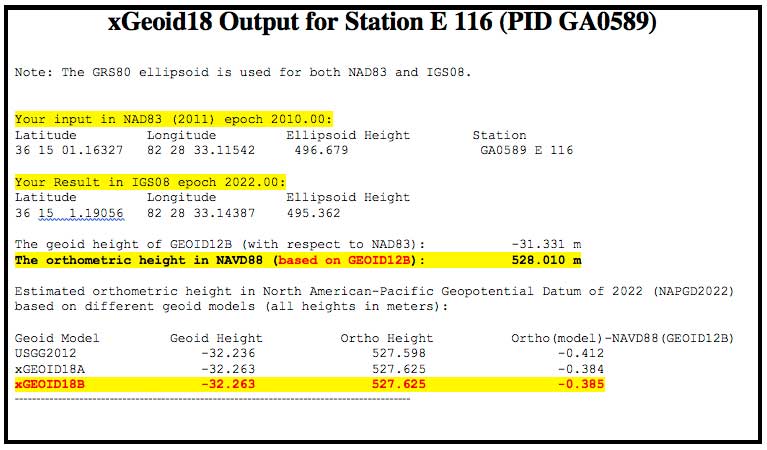
    Users can also obtain a xGeoid18B value for the station. The box titled “xGeoid18 Output for Station E 116 (PID GA0589)” provides the output of the xGeoid18 using NGS’ xGeoid18 interactive web service. It should be noted that the xGeoid18 output only provides the NAVD 88 orthometric height using GEOID12B; it does not include the published NAVD 88 orthometric height from the NGS Datasheet.

    xGeoid18 Output for Station E 116 (PID GA0589)

    Note: The GRS80 ellipsoid is used for both NAD83 and IGS08.
    Data: National Geodetic Survey

    The box titled “Different Height Values for Station E 116 (PID GA0589)” provides three different height values that are currently available from NGS web services. These different heights could lead to confusion if users are not careful. Most users won’t be using the experimental geoid interactive web service to compute an estimate of an orthometric height but all users should provide the appropriate metadata to avoid any confusion.

    Different Height Values for Station E 116 (PID GA0589)
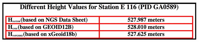
    Chart: National Geodetic Survey Chart: National Geodetic Survey

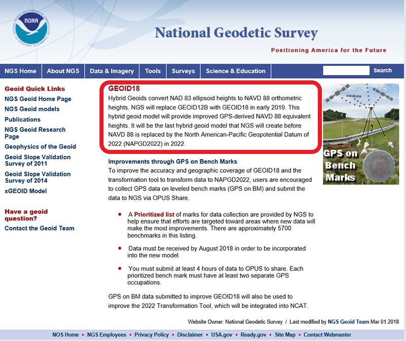
    The hybrid geoid model GEOID18 is currently being developed and is not ready to be published, but there is a web page that highlights that it will replace GEOID12B in early 2019 [see box titled “Hybrid GEOID18 Website“] GEOID18 values will be similar to GEOID12B because both hybrid geoid models are made to be consistent with published NAVD 88 values. Saying that, there will be differences especially in areas where the GPS on BMs program identified stations that have moved since the last time they were leveled and, therefore, they were not used in GEOID18.

    Hybrid GEOID18 Website

    Photo: National Geodetic Survey Photo: National Geodetic Survey

    My last column provided an update and status report on stations observed in support of the 2018 GPS on BMs program. Many stations with potential invalid published orthometric heights have been identified by the GPS on BM program. This information will be very useful to the surveying and mapping community as well as to NGS. Once NGS publishes the next hybrid geoid model, GEOID18, OPUS results will probably provide an estimate of the NAVD 88 orthometric height computed using GEOID18 similar to what it does now using GEOID12B. In my opinion, the results of GEOID18 will be better than GEOID12B in most areas of the United States and will be helpful in identifying stations that have moved since they were last leveled.

    NGS’ official date for accepted data for inclusion in the next hybrid geoid model, GEOID18, ended September 21, 2018. Continuing to submit your results to OPUS Shared will provide a way for others to analyze the results to determine whether a station has an issue that requires attention. New OPUS shared results will be very useful for evaluating the reliability of the model. After the hybrid geoid model, GEOID18, is published, NGS’ GPS-on-Bench-Mark Program will expand to include other regions and will focus on data to improve NGS datum transformation tools. Further columns will address differences between GEOID12B and GEOID18 after GEOID18 officially replaces GEOID12B.
  • U-blox partners with Arvento on multi-purpose tracker

    U-blox partners with Arvento on multi-purpose tracker

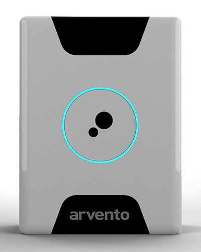
    Treyki Mini relies on u-blox positioning and wireless communication technologies.

    Photo: Arvento/u-blox
    Photo: Arvento/u-blox

    U-blox, a global provider of positioning and wireless communication technologies, is partnering with Arvento Mobile Systems, a Turkey-based fleet telematics company, to develop a compact people and asset tracking device with a long battery life.

    The Arvento Treyki Mini has eight operating modes, including special settings for tracking children (with geofencing) and senior citizens (with an integrated fall sensor). It is also suitable for use in sports, racing and asset management. It can also be used as an emergency beacon.

    The tracker has an onboard positioning receiver, and reports its location using an internal GSM/GRPS modem. It can operate for up to seven days from its 900mAh LiPo rechargeable battery before it needs to be recharged.

    Photo: Arvento/u-blox
    Photo: Arvento/u-blox

    The Treyki Mini relies on the u-blox ZOE-M8Q concurrent multi-GNSS module to discover its location. This system-in-package (SiP) offering is 4.5 x 4.5 x 1.0 millimeters. It provides high accuracy thanks to its ability to receive 72 channels simultaneously, from up to three different GNSS constellations, the company said.

    It also offers reliable positioning in challenging environments because it has a sensitivity of –167 dBm and is energy efficient.

    Communications for the Treyki Mini are provided by the u-blox SARA-G340 dual-band GSM/GPRS module — its very low standby power of less than 0.90 mA helps extend the Mini’s battery life. The SARA-G340 module also supports firmware-over-the-air (FOTA) updates, enabling Arvento to continue to refine the Treyki Mini after production.

    “The Treyki Mini is the result of a very close collaboration between Arvento and u-blox to optimize its size and power consumption,” said Özer Hıncal, general manager, Arvento. “We expect that the strong sense of partnership that evolved between our two companies during the development of the Treyki Mini will lead to further collaboration in the future, especially when it comes to telematics system solutions.”

  • ESA’s Pioneer mission sends GNSS-RO nanosatellites into orbit

    ESA’s Pioneer mission sends GNSS-RO nanosatellites into orbit

    News from the European Space Agency (ESA)

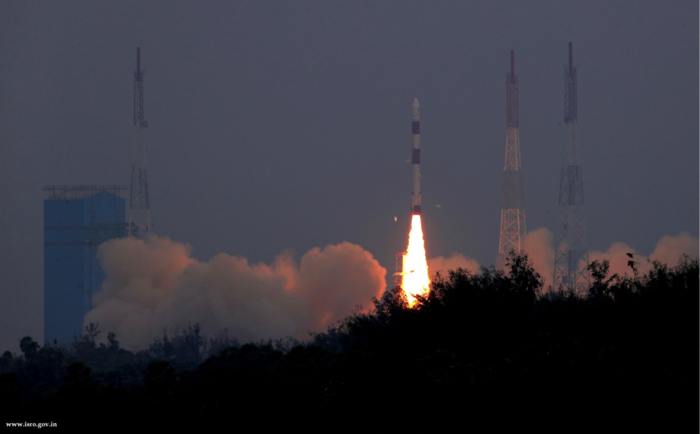
    Two tiny GNSS-RO nanosatellites now circle the Earth, ready for action. The first European Pioneer mission lifted off Nov. 29 from Sriharikota, India, to put the satellites into orbit.

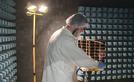
    One of Spire's Satellite Manufacturing Technicians (Tomasz Chanusiak) tests the Radio Frequency capabilities of a LEMUR2 nanosatellite in Spire's cleanroom in Glasgow, Scotland. (Photo: ESA)
    One of Spire’s Satellite Manufacturing Technicians (Tomasz Chanusiak) tests the Radio Frequency capabilities of a LEMUR2 nanosatellite in Spire’s cleanroom in Glasgow, Scotland. (Photo: ESA)

    The shoebox-sized satellites were launched at 04:27 GMT into low Earth orbit by the Indian Space Research Organisation’s PLSV launcher, and opened their first communication windows with their owner, Spire Global, less than an hour after they separated from the rocket.

    Both satellites were developed under ESA’s ARTES Pioneer programme, and will aim to prove the value of using nanosats for space-based GNSS Radio Occultation (GNSS-RO).

    GNSS-RO. GNSS-RO is the process of using satellites to measure how GNSS signals are refracted by the Earth’s atmosphere. Experts can use these measurements to glean temperature, pressure and humidity information for weather forecasting and climate change monitoring.

    In contrast, weather data gathered by weather balloons and aircraft can only reach certain altitudes, leaving the higher atmospheric layers untouched.

    Satellites have no such restrictions. They can gather massive amounts of this data from the ground up to the mesosphere as they fly over the Earth. This is usually done by large satellites. Spire’s nanosatellites weigh just 5 kg each, and were assembled and tested entirely by Spire in under three months, at their headquarters in Glasgow, Scotland.

    Named “Space as a Service,” the Spire Pioneer mission intends to prove that nanosat GNSS-RO is a commercially viable alternative to traditional methods.

    Photo:
    Two nanosatellites built by Spire Global were launched into low Earth orbit Nov. 29. (Photo: ISRO)

    The two tiny satellites will collect and distribute GNSS-RO data during their commissioning phase, after which they will go into full commercial data production mode, gathering weather information for meteorological institutions, maritime and aviation customers on demand.

    ESA’s Pioneer initiative partners with companies like Spire to help them provide this kind of in-orbit demonstration and validation for third parties.

    “We saw a gap in the market for what we call space mission providers: companies that offer all aspects of a space mission to validate a new technology or service for the benefit of others,” said ESA Pioneer Programme Manager Khalil Kably. “ESA is always looking to champion innovation in the space industry, and the idea of Pioneer is that these space mission providers can help this by being a one-stop shop for in-orbit demonstration and therefore reduce the barriers and complexity that can stifle new ideas.”

    “Spire has been focused on developing unique data sources with high frequency updates for the entire Earth and has over 60 LEMUR-2 class satellites deployed in space complimented with a global ground station network,” Spire Global CEO Peter Platzer said. “Under Pioneer, we can offer our extensive experience in manufacturing and managing small spacecraft like these to those who cannot afford to waste money and time doing it themselves. This work with ESA helps further support the global development of commercial aerospace’s potential to make space access universal.”

    “These incredibly clever shoebox-sized satellites built in Glasgow could slash the complexity and cost of access to space, presenting an exciting opportunity for the UK to thrive in the commercial space age,” UK Space Agency Chief Executive Graham Turnock said. “Through our £4m development funding, the government’s Industrial Strategy and by working closely with our international partners, we are helping UK businesses transform their ideas into commercial realities, resulting in jobs, growth and innovation.”

  • Tersus introduces Oscar GNSS RTK system

    Tersus introduces Oscar GNSS RTK system

    Photo: Tersus GNSS
    Photo: Tersus GNSS

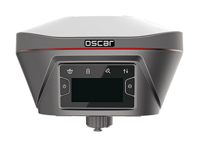
    Tersus GNSS Inc. has launched Tersus Oscar, its new generation GNSS real-time kinematic (RTK) system.

    Oscar is an all-in-one GNSS receiver that can be used as rover or base system. Paired with a Tersus TC20 controller or A11 mobile terminal, Oscar can more efficiently meet customer application requirements for the optimal surveying solution, according to Xiaohua Wen, founder and CEO of Tersus GNSS.

    “Last year, we launched the David GNSS receiver,” Xiaohua said. “This year, we are very excited to introduce an advanced version of David; we named it Oscar.”

    Oscar supports calibration-free tilt compensation function, meaning a leveling pole is no longer required. Configuration is made easy with a 1.3-inch interactive screen. With an internal high-performance multi-constellation and multi-frequency GNSS board, the Oscar GNSS receiver can provide high accuracy and stable signal detection, the company said.

    The high-performance antenna can speed the time to first fix and improve anti-jamming performance. The built-in large capacity battery can support up to 10 hours of fieldwork.

    A radio module in the package supports long-distance communication. With its rugged housing material, Oscar is protected from harsh environments.

  • Septentrio launches tiny Mosaic high-precision GNSS module

    Septentrio launches tiny Mosaic high-precision GNSS module

    Septentrio has launched the Mosaic high-precision GNSS receiver module.

    Despite its compact size (31 x 31 x 4 millimeters,  1.29 x 1.29 x 0.15 inches), the Mosaic module supports more than 30 signals from all six GNSS constellations, L-band and various satellite-based augmentation systems, the company said.

    As a multi-band module tracking all GNSS satellites in view, it is also designed to support future GNSS signals.

    It also supports correction services, and uses real-time kinematic (RTK) technology, together with Septentrio’s algorithms, to guarantee maximum accuracy and availability. The surface-mount design of Mosaic is optimized for automated assembly and ease of integration, with a full library of well-documented and flexible interfaces.

    “Our new Mosaic module represents the best-in-class option for reliable and scalable position accuracy, with integrity,” said Chris Lowet, product manager at Septentrio. According to Lowet, it provides RTK positioning with a power consumption of 0.6-1 W, and requires no or minimal additional components for the design-in. “These characteristics make it an ideal positioning cornerstone for a variety of mass market UAV, autonomous and robotics applications,” Lowet said.

    Photo: Septentrio
    Photo: Septentrio

    Robustness to interference. Due to the natural weaknesses of distant GNSS signals and a crowded radio-frequency spectrum, GNSS-based services are vulnerable to unintentional radio-frequency interference (RFI). They are also vulnerable to intentional RFI, attacks intended to disrupt receivers by means of counterfeit GNSS-like signals (known as spoofing), and to intentional transmission of RF energy to mask GNSS signals with noise (known as jamming).

    To defend against these threats, Mosaic features Septentrio’s AIM+ technology. AIM+ can suppress the widest variety of interferers, from simple continuous narrowband signals to complex wideband and pulsed jammers, the company added. In addition, the integrated spectrum analyzer allows the RF environment around any Mosaic module to be viewed in real time in both time and frequency domains.

    Effective interference countermeasures against threats to GNSS signals also require constant knowledge of the changing RF environment. The Mosaic module helps analyze these threats by continuously and automatically monitoring the GNSS frequency spectrum to detect, characterize, log and mitigate interference events when needed.

  • Tesla announces 1 billion driverless miles

    “As of today [Nov. 28] Tesla owners have driven 1 billion miles with Autopilot engaged,” the company announced via tweet.

    The Autopilot feature became available in 2015 and now comes  on all new Tesla models with a $5,000 activation fee at the time of purchase or $7,000 if selected later.

    The company is training its “neural networks” to improve its self-driving system.

    Photo: Tesla
    Photo: Tesla

    Tesla’s global fleet totals more than half a million vehicles, and recently marked a 20-billion mile step of total electric miles driven, the company said.

    The Autopilot system can also function in the background of the vehicle, without being activated and with no input on control. Thus it gathers data from many more billions of “drivered” miles about its environment and potential Autopilot behavior.

    The company previously mentioned the 1 billion-mile autonomous mark as the minimum it would need to move Autosteer from beta to a regular feature.

    Updates to Autopilot are planned for 2019, including new hardware that will aid in the rollout of the company’s Full Self-Driving system, possibly by the end of that year.