High-tech aerial laser surveying is being employed to reveal the hidden archaeology of an Iron-Age hill settlement in Lancashire, England.
Visually, the archaeological features are difficult to see, but a Bluesky laser survey, commissioned by the Morecambe Bay Partnership, is expected to reveal previously undiscovered details of a settlement at Warton Crag. Identified as an important Heritage at Risk site, the site has already been subject to low-level archaeological investigations, which have identified remains from a small, well defended hill fort.
“It is imperative that we get a better definition of the archaeological remains that are currently ‘hidden’ by the dense vegetation cover,” said Louise Martin, H2H cultural heritage officer at the Morecambe Bay Partnership. “This will enable us to develop conservation strategies for the site and work towards reducing the risk to the archaeological remains. The site is currently on Historic England’s ‘at risk’ register, so this work is crucial in developing partnerships and strategies to protect the monument for future generations.”
The Bluesky lidar system uses lasers to accurately measure the earth’s terrain and record features on the ground in 3D. A dedicated survey plane is equipped with aerial photography equipment and will fly over the site during the winter months when the tree and canopy cover is at its minimum.
Bluesky will process the millions of individual laser measurements to create detailed 3D computer models of the Earth’s relief — a Digital Terrain Model (DTM) — and ground surface including buildings and vegetation — a Digital Surface Model (DSM). This will allow the Morecambe Bay Partnership to model scenarios and strategies and share information with project partners.
Geneq has introduced a new “all-in-one” GPS, GNSS and RTK Data Collector Series, the SXPro.
The professional-grade series of handheld receivers is accurate, rugged and competitively priced, the company said.
Standard features include an extra-long battery life of more than 10 hours on a charge as well as a large outdoor-viewable touchscreen. The handhelds are rated IP65 for protection against water and dust.
The SXPro handheld is also equipped with a 5-megapixel autofocus camera and Microsoft utilities. The SXPro is sold as a fully loaded package that includes a spare battery, hard carrying case and Field Genius Survey Data Collection software.
The SXPro series is built for mobile survey and GIS users for applications such as water, electric and gas utilities; transportation; mining; agriculture; and forestry.
The SXPro RTK (real-time kinematic) model offers 220 multi-constellation channels for centimeter accuracy with RTK networks. A surveyor-grade external dual-frequency antenna and cables are included.
The SXPro GNSS offers 372 multi-constellation channels for sub-meter accuracy with SBAS corrections.
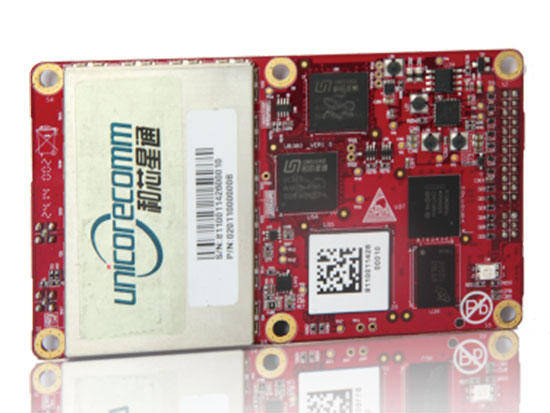
The UB380 GPS/GLN/BDS tri-constellation octa-frequency high-precision board.
High-end GNSS board
For high-precision positioning, navigation and GBAS applications
The UB380 multi-GNSS receiver has 384 channels, based on Unicore’s multi-GNSS system on a chip. It features Unicore’s latest real-time kinematic (RTK) engine, which can process triple-frequency BDS and GPS and dual-frequency GLONASS observation data. This can significantly reduce initialization time, improve position accuracy and enhance reliability in difficult environments such as city canyon and canopy, as well as make the long baseline RTK possible. The receiver board can support GPS L1, L2 and L5; GLONASS L1, L2; and BDS B1, B2 and B3. The support of GPS L2P and L2C can satisfy the high-precision requirements of GBAS reference station equipment. The UB380 is compatible with industry-standard GNSS boards in size, interfaces and electrical standards.
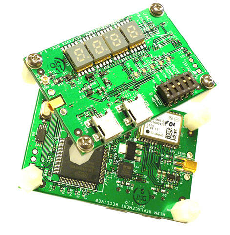
M12M Replacement Receiver GNSS module. Photo: Jackson Labs Technologies
Legacy receiver module
Plug-and-play upgrade for xli server, fury GPSDO
The M12M Replacement Receiver released is form, fit and function compatible to the legacy Motorola M12M and M12+ timing and navigation receivers. It uses an eighth-generation GNSS timing-enabled receiver, allowing 72 GNSS-channel reception with any two GNSS systems being received simultaneously. It adds configurability via USB ports and dual in-line package (DIP) switches and various status displays. GPS, GLONASS, BeiDou, QZSS and SBAS signals can be received. The module supports NMEA, Motorola binary and u-blox binary as well as SCPI (GPIB) communication protocols; is designed to allow plug-and-play retrofit of equipment designed for legacy Motorola receivers; and is certified as a plug-and-play upgrade to the Symmetricom/Microsemi XLI server and the Jackson Labs Technologies Fury GPSDO. It can be used to retrofit products for GLONASS/BeiDou compatibility. The module enhances performance parameters such as time to first fix; position, velocity and timing accuracy; tracking sensitivity; the addition of SBAS (differential compensation) capability; and the addition of external interfaces such as USB and a synthesized frequency output.
High-gain, high-rejection family designed for cell and telecom
The TW3150/52 antennas feature a 50-dB low-noise amplifier (LNA) gain to handle long cable runs often associated with installation on telecommunications towers. They cover the GPS L1 and SBAS (WAAS, EGNOS and MSAS) frequency bands and provide excellent cross-polarization rejection and enhanced multipath rejection.The TW3150 antenna features a four-stage dual-filtered LNA, while the TW3152 antenna includes an additional SAW pre-filter. This provides better than 80-dB of signal rejection above 1610 MHz and below 1545 MHz. The antennas are IP67 and MIL-STD-801F Section 509.4 compliant to withstand challenging environmental conditions.
Provides support for GPS, GLONASS and BeiDou with MediaTek
The ORG1510-MK Multi Micro Hornet is a fully integrated multi-GNSS (GPS, GLONASS and BeiDou) module. The miniature low-power architecture is designed to provide a GNSS component to devices that require fully featured components with small footprints, such as UAVs designed to follow action sports and other fast-moving activities or wearables. The ORG1510-MK contains the MediaTek MT3333 chip, which supports a fast update position calculation rate, and contains an onboard flash memory that does not erase when power is off. It consumes little power with the use of both standby mode and backup mode, and, in advanced applications, a periodic mode that can turn the device on and off when in backup or standby.
Designed for recording sports activities, the FLYPRO XEagle UAV has replaced traditional UAV remote controllers with the XWatch, a smartwatch designed to control the XEagle. Users can control the devices to take off, land and follow, as well as adjust flight height with one click on the wrist within 300 meters. The smartwatch design enables users to fly the aerial vehicles to take high-definition pictures and videos while engaging in intense sports. A voice-control feature allows users to fly the XEagle without moving their hands using commands such as “FLYPRO, take off” and “FLYPRO, follow me”.
Thermal imaging camera core designed for integration
FLIR Tau 2 thermal imaging cameras are suited for demanding applications like UAVs, thermal weapon sights and handheld imagers. Improved electronics now give Tau 2 even more capabilities, including radiometry, increased sensitivity (<30 mK), 640/60 Hz frame rates, and powerful image processing modes that dramatically improve detail and contrast. Since the electrical functions are common between the Tau 2 640, 336 and 324, integrators have direct compatibility between the different camera formats, and Tau camera versions share many of the same lens options.
Amazon’s latest version is designed to deliver packages in 30 minutes
Source: Amazon
A new drone design introduced by Amazon for its planned Prime Air Delivery service is larger than the previous quadcopter and has a more advanced design, including the ability to operate with an auto-loading system that sets the payload inside an internal carrier bay. The hybrid design combines vertical lift and horizontal flight capabilities using lift fans and a pusher prop. The drone is capable of flying at an altitude of about 400 feet (122 meters) at about 55 mph (88 km/h) for a range of 15 miles (24 kilometers). It has sense-and-avoid situational awareness technology and is designed to deliver small packages in under 30 minutes.
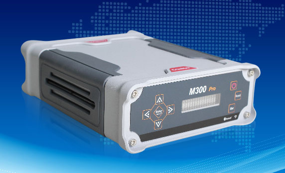
The M300 Pro is a multi-purpose CORS GNSS receiver designed for applications such as positioning infrastructure, active geodetic network, deformation monitoring, machine guidance, harbor construction, land surveying and marine surveying. Designed for reference stations, the M300 Pro tracks GPS, GLONASS and BeiDou (B1, B2, B3), and will track Galileo, QZSS and other coming constellations. Its web server function enables remote control for access, configuration, programming, data download, reboot/restart, firmware update and code registration. It is compatible with many kinds of CORS software, using the standard data format RTCM and the various data transfer protocols such as UDP, TCP and NTRIP. Raw GNSS observation data can be saved in RINEX format and remotely downloaded. Multiple ports can be configured and connected with external sensors such as meteorological sensors, barographs and inclinometers. The PPS output function provides a guarantee for precision timing. It also has the functionality of event mark and external memory.
The Leica Velocity and Displacement Autonomous Solution Engine (VADASE) detects fast movements of man-made and natural structures in real time, running on board Leica reference stations and monitoring receivers. VADASE provides an in-depth look at accurate, high-rate velocity and displacement information of various activities and structures. It gives engineers and researchers complete, precise and reliable monitoring information. VADASE delivers actionable information independent of any GNSS real-time kinematic (RTK) correction service.
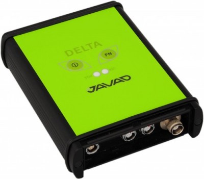
GNSS receiver with onboard memory for data storage
The DELTA-3 receiver has 864 GNSS channels, along with three powerful processors and program memory in a single chip, which uses less power and makes the total system less expensive. The 864 channels allow tracking of all current and future satellite signals. Delta-3 can track and decode the QZSS LEX signal messages. It is a powerful and reliable receiver for high-precision navigation systems, including high-dynamic systems, for machine and traffic control, high-precision surveying, and geodynamics and aerogeophysics applications. Delta-3 can operate as a receiver for post-processing, as a Continuously Operating Reference Station (CORS), or as a portable base station for real-time kinematic (RTK) applications, and as a scientific station collecting information for special studies such as ionosphere monitoring.
A configuration of ArcGIS and a JavaScript application
Photo Survey is designed for local governments to publish street-level photo collections and conduct focused property surveys that can identify blight, damaged structures or construction activity. It leverages location-enabled photos produced by many commercially available cameras and simplifies data processing so street-level photo collections can be gathered on a regular basis. Photo collections can then be combined with relevant survey questions in an ArcGIS Online map, and shared with the Photo Survey application. Once complete, the Photo Survey application can be used by the general public or local government staff to review street-level photos and complete property surveys.
Magellan is showcasing its new eXplorist TRX7 off-road vehicle navigation solution for the 4×4 and Powersports vehicle consumer market at CES 2016, a consumer electronics and technology trade show held Jan. 6–9 in Las Vegas. The OHV navigation solution delivers detailed 3D maps, more than 44,000 vehicle trails and community generated trails, improved driver safety and a superior user experience, the company said in a news release.
The TRX7 will be displayed in the Magellan booth at CES, located in South Hall MP25441.
“Magellan’s new eXplorist TRX7 is the only complete off-road navigator for adventuring,” said Stig Pedersen, associate vice president of product management for Magellan. “Pre-loaded trail maps and crowd-sourced trails provide a constantly updating platform, allowing users to plan adventures, navigate, and add pictures and comments to trails. Finally off-roaders have an all-in-one solution that will safely guide them through some of the most fun and exciting trails in the U.S. and Canada.”
The device
Built to withstand the harsh demands of off-roading, the Magellan eXplorist TRX7 features:
16GB onboard memory and a 64GB MicroSD card expansion slot.
Three different mounting options: Windshield Suction Cup Mount, Genuine Ram Handlebar Rail Mount or Genuine Ram Windshield Suction Cup Mount.
The maps
The Magellan off-road vehicle platform’s trail maps are cloud-based, dynamic, and will continue to grow and be improved by both Magellan and through crowd-sourced additions from the Magellan OHV user community, the company said. The off-road maps feature high-resolution 3D and 2D terrain and contour elevation lines; food, gas, lodging and general service POIs; third party trail guides; and more.
The Magellan TRX7 allows users plan, track and save trail rides. Its OHV web portal lets users add pictures and comments to their trail rides and share them with friends, family, and off-road and outdoor communities. Members of Magellan’s off-road vehicle online community earn achievement badges for posting and sharing “dirt miles” traveled and total number of trails posted.
The portal also is integrated to social media sites such as Twitter, Facebook and Instagram, users are able to post their greatest trail adventures.
Marvell, a connectivity and semiconductor company, has launched its Near Field Communication (NFC) 88NF100 Controller with Active Load Modulation (ALM) to support the smallest antenna sizes critical to mobile, IoT, wearable and automotive applications.
Adhering to the NFC Controller Interface (NCI) Technical Specification version 1.1, the 88NF100 provides an extended operating range and is extremely energy-efficient to enable extended battery life for power critical applications.
The 88NF100’s ALM technology supports the smallest antenna sizes to enable OEMs to implement NFC capabilities into small form factor designs, such as for mobile, the Internet of Things (IoT), wearable and automotive applications. The controller has extremely low power operation in polling mode to provide increased battery life for power critical applications and three single-wire protocol (SWP) interfaces to secure element (eSE) devices, for for secure payments.
The patented two-pin antenna interface supports a maximum distance of two meters between the chip and antenna, supporting devices where the antenna must be located far away from the chip, such as with automotive and printer applications, in addition to designs with tight space constraints, including smartphones and wearable devices.
Seamlessly integrating with Marvell’s Wi-Fi, Bluetooth and ZigBee solutions, the 88NF100 is compliant with the NCI Technical Specification version 1.1 to leverage existing middleware and applications and supports GSMA, ISO and EMVCo industry standards.
“As consumers demand smarter and more connected devices every year, manufacturers are increasingly faced with the challenge of incorporating advanced technology features into elegant and small form-factor designs. Marvell’s 88NF100 controller with ALM technology is designed to enable OEMs to incorporate advanced NFC technology into compact and energy-efficient designs with ultra-small antennas,” said Kevin Tang, senior director of marketing, Wireless Connectivity Business Unit at Marvell. “Marvell’s wireless technology enables the ultimate performance, battery life and operating range, making the 88NF100 ideal for NFC applications in Mobile payments, point of sale (POS) systems, Smart home connected devices, Smart watches and vehicles.”
Key features of the Marvell 88NF100 include:
Low-power consumption. The 88NF100 supports all data rates up to 848 kbps and operates with a low polling current of 60uA, making it ideally suited for power critical applications.
ALM integration. The controller’s ALM technology supports smaller antennas; and allows placement of the antenna up to two meters from the 88NF100.
Advanced digital processing for reader mode. The 88NF100’s signal processing has been optimized for better performance, enabling better reading distance in peer-to-peer (P2P) modes.
Advanced low-battery operating mode. The controller can operate on a very low current from the battery, ensuring that mobile applications deliver the same performance level in card emulation (CE) mode when the phone is powered on or off.
Compact package with low pin count. The 88NF100 has embedded wafer level ball grid array (eWLB) 2.5 x 2.5 and a compact 4 x 4 quad-flat no-leads (QFN) package.
Local Interconnect Network (LIN) interface. The LIN interface is designed to enable developers to build low cost NFC LIN nodes for the automotive industry and natively support the automotive LIN communication protocol.
Aman Enterprises introduces NMEA-BT — a Bluetooth iOS adapter that enables any high-precision GNSS receiver with a serial port to connect to an iPad or iPhone.
The NMEA-BT adapter is a small, weatherproof device that solves the problem of connecting non-iOS GNSS receivers and other field sensors to iOS devices. It connects to the iOS devices wirelessly using the native Bluetooth built into the iOS devices.
By replacing the iOS device’s internal GPS location information with the location information from the intrinsically more accurate external GNSS devices used by mapping and survey professionals, NMEA-BT allows users to pair external GNSS devices to their location-enabled iPhone or iPad app. The patent-pending product helps preserve the user’s investment in sub-meter and centimeter GNSS receivers and other sensors while users migrate their workforce to iOS devices.
A free app from the Apple iTunes App Store (NMEA Talker) enables the user to specify any required GPS connection parameters; connect to a local cellular RTK network (NTRIP) or a Direct IP (DIP) based correction service; and feed the corrections to the GNSS receiver, allowing for centimeter accuracy in real time in the field. The app can also be used to display error notifications like high PDOP, loss of an RTK correction, loss of satellite lock.
In addition to connecting to GNSS devices, users can connect to other sensors like laser rangefinders, resistographs, underground cable locators, and commercial weigh scales that output NMEA-formatted data.
For developers, they have full access to the entire raw NMEA stream of data from multiple devices without sacrificing app security or design architecture. No proprietary libraries are required to access the NMEA data stream.
GPS/GNSS Receiver Compatibility
The NMEA-BT has been tested with the following receivers:
John Deere StarFire
Trimble Pro 6, Geo Explorer, 372
Casel H372
Topcon HiPer series
Septentrio APS and NR series
Geneq SXBlue series
Ag Leader 6000 and 6500 series
Raven Industries – Envizio Pro series
Novatel
The only requirement to interface the NMEA-BT adapter is that the GNSS receiver must output at least the $GPGGA and $GPRMC messages via serial port.
At CES in Las Vegas, HERE unveiled the HERE HD Live Map, an advanced cloud-based map asset commercially available for vehicles today. HERE is demonstrating HD Live Map at CES: Central Plaza, Booth #CP-2.
Ready to be deployed in connected vehicles in North America and Western Europe, HD Live Map creates a highly detailed and dynamic representation of the road environment, enabling a vehicle to effectively “see around corners” beyond the reach of its on-board sensors.
HD Live Map is an integrated offering, consisting of multiple layers of data delivered in a map-tile format. It is designed to enhance both Advanced Driver Assistance Systems (ADAS) and automated driving functionality, and therefore make driving more comfortable and enjoyable.
HD Live Map includes data which tends to have high permanency, such as lane level information; data which is temporal in nature, such as road construction, traffic and accidents; and analytics data, including speed profile information that informs the vehicle about how to drive based on actual human behavior data.
With highly automated driving set to become prevalent in the next few years, the immediate next step for the automotive industry is to capitalize on the new generation of ADAS that leverages wireless network connectivity and the cloud.
With HERE HD Live Map, automakers have the ability to enhance a vehicle’s ADAS functionality — such as adaptive cruise control, adaptive headlights and curve speed warnings — by giving it access to more accurate and more reliable near real-time content and contextual information about its environment. In doing so, the industry can help drivers build the prerequisite trust and familiarity they need to feel comfortable with increasing levels of vehicle automation.
“As we move towards higher levels of vehicle automation, drivers need to feel that their car is making the right decisions on their behalf,” Floris van de Klashorst, HERE’s vice president of automotive. “When it comes to trusting your car, having consistent real-time awareness of road conditions near and far is absolutely critical. With HD Live Map serving this need, we believe it will become the car industry’s most intelligent vehicle sensor.”
Self-maintaining map. HERE HD Live Map is the first map from HERE that is self-maintaining: through multiple modes of sensor aggregation and ingestion the vehicle’s map is updated and delivered in near real-time.
For example, if vehicle sensors detected a speed limit sign which is inconsistent with what is currently in the map, the map would update accordingly so that other vehicles driving approaching the same spot have the new, correct information. This is important for ADAS functionality such as adaptive cruise control.
Similarly, if a new lane closure was reported, the map would update accordingly so that other vehicles approaching the area can already prepare to switch lanes or alternatively re-route if traffic is heavy.
HERE HD Live Map delivers connected ADAS content via layered live tiles, with dynamic traffic flow data, real-time incident reporting and speed profile data derived from rich behavior information.
HD Live Map is also data-efficient, requiring a small data footprint, with new events able to be layered on the map without the need to update the whole map itself. The small file sizes within each live tile make the delivery of highly precise data much leaner, thus reducing bandwidth requirements.
In the near-term, HD Live Map utilizes a variety of data gathered and delivered by the HERE location platform to enhance the vehicle and the driver’s awareness of what’s happening on the road.
As vehicle automation increases in the future, HD Live Map is ready to serve as an agnostic location cloud, ingesting, aggregating and delivering in near real-time ever vaster quantities of data produced by a variety of sources, especially vehicle sensors. For example, HERE is exploring further enriching its platform with new sensor data from Audi, BMW and Mercedes-Benz vehicles, which would benefit all automakers deploying HD Live Map.
HERE has already been providing either parts or full specifications of HD Live Map for automated driving testing purposes to more than ten automotive companies. Many of those have taken advantage of HD Live Map data HERE is offering of specific stretches of open road in Silicon Valley and Michigan in the United States, as well as in France, Germany and Japan.
Now, with HD Live Map offered across key regions, HERE is able to support automakers seeking to widen and deepen their automated driving development efforts. In supporting larger testbeds, HERE intends to continue to refine HD Live Map together with automakers to ensure it is optimized for their needs today and tomorrow.
“Highly-detailed map data is not only very useful but a requirement for full-featured automated and autonomous driving. In the near term, highly-detailed map data will enhance the performance and benefits of current-generation driver assist technologies; over the longer term, they will enable more effective and efficient operation of vehicles altogether by drivers or self-driving cars. Adding a feedback loop to continually gather, update and share the latest road data will further elevate the technology’s potential,” analysts at IHS Automotive said.
The Alaska Geologic Map shows the generalized geology of the state, each color representing a different type or age of rock. (Image: USGS)
A new digital geologic map of Alaska is being released today, providing land users, managers and scientists geologic information for the evaluation of land use in relation to resource extraction, conservation, natural hazards and recreation.
The U.S. Geological Survey (USGS) map gives visual context to the abundant mineral and energy resources found throughout the state in a detailed and accessible format.
“I am pleased that Alaska now has a state-wide digital map detailing surface geologic features of this vast region of the United States that is difficult to access,” said Suzette Kimball, newly confirmed director of the USGS. “This geologic map provides important information for the mineral and energy industries for exploration and remediation strategies. It will enable resource managers and land management agencies to evaluate resources and land use, and to prepare for natural hazards, such as earthquakes.”
“The data contained in this digital map will be invaluable,” said National Park Service Director Jonathan B. Jarvis. “It is a great resource and especially enhances the capacity for science-informed decision making for natural and cultural resources, interpretive programs, and visitor safety.”
“A better understanding of Alaska’s geology is vital to our state’s future. This new map makes a real contribution to our state, from the scientific work it embodies to the responsible resource production it may facilitate. Projects like this one underscore the important mission of the U.S. Geological Survey, and I’m thankful to them for completing it,” said Sen. Lisa Murkowski, R-Alaska.
This map is a completely new compilation, carrying the distinction of being the first 100 percent digital statewide geologic map of Alaska. It reflects the changes in our modern understanding of geology as it builds on the past. More than 750 references were used in creating the map, some as old as 1908 and others as new as 2015. As a digital map, it has multiple associated databases that allow creation of a variety of derivative maps and other products.
“This work is an important synthesis that will both increase public access to critical information and enhance the fundamental understanding of Alaska’s history, natural resources and environment,” said Mark Myers, Commissioner of Alaska’s Department of Natural Resources. “I applaud the collaborative nature of this effort, including the input provided by the Alaska Division of Geological and Geophysical Surveys, which will be useful for natural disaster preparation, resource development, land use planning and management, infrastructure and urban planning and management, education, and scientific research.”
Geologists and resource managers alike can utilize this latest geologic map of Alaska, and a lay person can enjoy the colorful patterns on the map showing the state’s geologic past and present.
More than other areas of the United States, Alaska reflects a wide range of past and current geologic environments and processes. The map sheds light on the geologic past and present. Today, geologic processes are still very important in Alaska with many active volcanoes, frequent earthquakes, receding and advancing glaciers and visible climate impacts.
“This map is the continuation of a long line of USGS maps of Alaska, reflecting ever increasing knowledge of the geology of the state,” said Frederic Wilson, USGS research geologist and lead author of the new map. “In the past, starting in 1904, geologic maps of Alaska were revised once a generation; this latest edition reflects major new mapping efforts in Alaska by the USGS and the Alaska state survey, as well as a revolution in the science of geology through the paradigm shift to plate tectonics, and the development of digital methods. Completion of this map celebrates the 200th anniversary of world’s first geologic map by William Smith of England in 1815.”
This map detail, of the Anchorage area, shows the city spread out on a plain of loose glacial deposits shown in yellow, and the bedrock making up the hillsides of Anchorage shown in green and brown. The rocks shown in green, called the Valdez Group, are sedimentary rocks formed in a trench 65 to 75 million years ago from thousands of undersea debris flows similar to the modern Aleutian trench where oceanic crust dives under continental crust (a subduction zone). The rocks shown in brown on the map are a chaotic mix of rock types called the McHugh Complex that were also formed about the same time, adjacent to this ancient subduction zone. Some time after deposition of the Valdez Group, hot fluids formed gold-bearing quartz veins; the veins were mined starting in the 1890’s. The rocks were pushed up, and attached (accreted) to North America through plate tectonic forces in the past 65 million years. The dotted line passing through the east side of Anchorage is the approximate trace of the Border Ranges Fault system, the boundary between the accreted rocks and the rest of the continent. This map detail, of the Anchorage area, shows the city spread out on a plain of loose glacial deposits shown in yellow, and the bedrock making up the hillsides of Anchorage shown in green and brown. The rocks shown in green, called the Valdez Group, are sedimentary rocks formed in a trench 65 to 75 million years ago from thousands of undersea debris flows similar to the modern Aleutian trench where oceanic crust dives under continental crust (a subduction zone). The rocks shown in brown on the map are a chaotic mix of rock types called the McHugh Complex that were also formed about the same time, adjacent to this ancient subduction zone. Some time after deposition of the Valdez Group, hot fluids formed gold-bearing quartz veins; the veins were mined starting in the 1890’s. The rocks were pushed up, and attached (accreted) to North America through plate tectonic forces in the past 65 million years. The dotted line passing through the east side of Anchorage is the approximate trace of the Border Ranges Fault system, the boundary between the accreted rocks and the rest of the continent. This map detail, of the Anchorage area, shows the city spread out on a plain of loose glacial deposits shown in yellow, and the bedrock making up the hillsides of Anchorage shown in green and brown. The rocks shown in green, called the Valdez Group, are sedimentary rocks formed in a trench 65 to 75 million years ago from thousands of undersea debris flows similar to the modern Aleutian trench where oceanic crust dives under continental crust (a subduction zone). The rocks shown in brown on the map are a chaotic mix of rock types called the McHugh Complex that were also formed about the same time, adjacent to this ancient subduction zone. Some time after deposition of the Valdez Group, hot fluids formed gold-bearing quartz veins; the veins were mined starting in the 1890’s. The rocks were pushed up, and attached (accreted) to North America through plate tectonic forces in the past 65 million years. The dotted line passing through the east side of Anchorage is the approximate trace of the Border Ranges Fault system, the boundary between the accreted rocks and the rest of the continent. (Image: USGS)
u-blox has released the u‑blox 8 GPS/GLONASS receiver platform. It complements the u-blox GNSS platform portfolio by addressing power sensitive usage, whereas the existing u-blox M8 platform continues to serve applications where navigation performance and highest accuracy are paramount.
u-blox 8 offers significant improvements, compared with its predecessor u-blox 7. The tracking sensitivity has been increased by 4 dBm, and is now -166 dBm.
The enhanced odometer functionality, a new geofencing feature, and optimized preset power save modes can halve the power requirements for sport products. Free-of-charge AssistNow for boosting GNSS acquisition performance, which is available online, offline or as an autonomous service, has been improved. It also makes the new positioning platform ideal for all battery powered devices, especially wearables and sports tracking.
“Nowadays many portable applications rely on a single coin battery; hence low power-spending is crucial,” said Uffe Pless, Product Marketing and Positioning, u‑blox. “u‑blox 8 has been developed for wearables and tracking applications, keeping in mind the need for low power consumption without compromising performance.”
u‑blox 8 is pin-compatible with u‑blox 7. It will be available as a chip and as modules in several form factors. Customer samples of u‑blox 8 chips and modules will be available by Q2 2016.
GNSS receiver maker Septentrio has announced the availability of its geographical information systems (GIS) PinPoint-GIS on the ArcGIS Marketplace.
PinPoint-GIS was developed to enable straightforward GIS data collection without the need for expensive additional software linking a GNSS receiver with the Esri ArcGIS Platform
PinPoint-GIS helps ArcGIS users make informed and timely decisions, Septentrio said. It turns GNSS data collected by Septentrio’s receivers such as the Altus NR2, Altus GeoPod and the AsteRx-U into actionable GIS data. Height and other project parameters are available directly in the ArcGIS workflow without any additional steps by the user.
Pinpoint GIS makes ArcGIS easily accessible through existing hardware — consumer commercial and ruggedized device, tablet or even smartphone — regardless of operating system. PinPoint-GIS Web makes ArcGIS available from a standard web browser or from an Android app, downloadable from Google Play.
The Android app works with Esri’s Collector for ArcGIS and provides an accuracy widget which confirms horizontal and vertical accuracy in a highly visible way. This brings the user the immediate security that the captured data meets the required accuracy in both the horizontal and vertical.
“Integrating ArcGIS functionality into PinPoint-GIS empowers ArcGIS Online users,” said Gustavo Lopez, PinPoint-GIS Product Manager. “With the click of a button, a PinPoint-GIS user can turn accurate and reliable GIS data collected from their Septentrio GNSS receiver into actionable data needed for smarter decisions, effective analysis and customized maps all within the easy-to-use ArcGIS.”
Broadcom Corporation has added a new GNSS wireless connectivity chip to its automotive portfolio, which it unveiled at CES 2016, being held this week in Las Vegas.
Automotive GPS shipments are expected to more than double by 2022, creating significant opportunities among component suppliers and increasing competition for market share. The chip offers wideband capture radio technology for simultaneous tri-band reception of all visible GNSS satellites including GPS, Galileo, QZSS, GLONASS, BeiDou and global SBAS augmentation systems.
Broadcom’s BCM89774 provides improved location and positioning while lowering power consumption for in-vehicle applications and reduces bill of materials cost for car makers, by integrating the sensor hub and CPU on a single chip.
The BCM89774 delivers original equipment manufacturers (OEMs) one of the most accurate solutions available today, Broadcom said. The new chip also improves positioning in dense urban environments and foliage-blocked areas to enhance the consumer experience.
Optimized to meet the rigorous standards of the automotive industry, the BCM89774 has been tested to AECQ100 automotive environmental stress requirements, is manufactured in TS16949 certified facilities, and offers full production part approval process (PPAP) support.
“Broadcom’s new GNSS connectivity chip for automotive keeps car makers and tier one suppliers ahead of the curve with advanced precision and reduced power consumption while lowering BOM cost,” said Richard Barrett, Broadcom Director of Automotive Wireless Connectivity. “By delivering premium products that meet automotive grade requirements, we are positioned for growth in this accelerating market.”
Key Features:
Low-power mode for emergency service and theft tracking applications
Location awareness capabilities added to traditional functions of a sensor hub for lower power consumption and BOM costs
Simultaneous reception of GPS, GLONASS, BDS, QZSS and Galileo navigation satellites
Support for global Satellite Based Augmentation System (SBAS) system
Management of CAN BUS inputs and sensors such as accelerometers, gyroscopes, and magnetometers to provide a fused sensor data tracking subsystem
Best-in-class acquisition, tracking sensitivity and time-to-first-fix in both cold and hot starts
Full pass through capability for external host-based systems
Tested to AECQ100 automotive environmental stress requirements and manufactured in TS16949 certified facilities
Full production part approval process (PPAP) support
As technology continues to march forward, and storage and data evaluation use grows, the surveyor and the farmer will begin to use each other’s skillsets to increase their own productivity. So how do we get there? First, we must establish how each side uses their prospective GPS tools.
As a child, I spent several summer vacations at my relatives’ farms in central Illinois. My early impression of working on a farm was one of long hours and hard work. Work and chores completed by my family members was very physical with no set hours to look forward to. My uncles didn’t get to set the schedules for rain and sun and had no say in whether or not a piece of equipment would break down.
What I encountered as a child taught me that there was no technology in farming; it was nothing but hard work. The thought of using something as high-tech as GPS would have made most old-time farmers laugh you right out of the coffee shop.
My career as a land surveyor has had its share of hard work at times, but it has been the technology that has always fascinated me. When I began as a rodman, the electronic distance meter allowed surveyors to measure distances more than a mile instead of hand taping the entire way, and with much more accuracy. Along the way, I’ve watched computer technology grow, with total stations that incorporate cameras and video and GPS receivers that provide accurate locations instantaneously.
That brings us to our modern-day crossroads. As surveyors, we are constantly trying to find ways to incorporate our skills into other occupations to increase productivity. We also see the modern farmer moving away from small family operations with only several hundred acres, morphing into farm management corporations with tens of thousands of acres as well as millions of dollars of equipment.
Efficiency is what they are after, and they are spending significant amounts of money on technology to make it happen. My own curiosity and research has opened my eyes to how far the farming profession has grown, and in many ways surpassed the land surveyor with technology. But I think there is still common ground that needs to be explored, so let’s start at the root of each profession.
The Farmer and the Surveyor
As different as the two professions may seem, farming and surveying have one large common link: data. More specifically, the tools, methods and procedures they operate to acquire the data used in their everyday jobs and projects.
The implementation of GPS equipment and the ability to collect location data has greatly improved the productivity of both professions, but for drastically different reasons. However, as technology continues to march forward, and storage and data evaluation use grows, the surveyor and the farmer will begin to use each other’s skillsets to increase their own usefulness.
So, how do we get there? First, we must establish how each side uses their respective GPS tools.
The Land Surveyor
The land surveyor and his or her staff use GPS daily, with varying degrees of accuracy. Here are a few examples:
Mapping-Grade GPS Device (>= 3 meters)
This handheld unit is primarily used for mapping utilities and improvements that don’t require high accuracy. The data and attributes acquired by this unit will be inserted into geographic information system (GIS) databases for inventory, and maintenance logs for future review and upgrade needs. Surveyors use these units for mapping items that require additional attributes and information necessary to improve the overall usefulness of a GIS database.
Differential GPS (<= 1 meter)
Differential GPS provides live positional solutions for applications that require more accuracy than mapping-grade GPS, at a reasonable equipment and operational price. These systems are used by aeronautical companies for mapping assistance, logistics companies for asset tracking, and emergency operations for 911 systems. These systems are also used by hydrographic surveyors for use in mapping lake and river bottoms as well as surveyors working in open pit mines, producing existing condition maps and volumetric surveys.
Survey-Grade GPS
Surveyors began implementing GPS equipment into their measuring repertoire in the mid 1980s with the introduction of data collection by static methods. This technique allowed for long-distance measurements with good accuracy and precision, but it came at an incredibly expensive cost.
By the mid 1990s, real-time kinematic (RTK) equipment was introduced, and gave the land surveyor a new gateway into long-distance measurement with shorter occupation time and less cost. Additional enhancements to RTK systems included on-the-fly initialization, increased data-collector capability, and cellular/long-distance radio networks.
These improvements allowed increased data-collection productivity, including mobile collection on all-terrain and survey vehicles. A topographic survey of a 40-acre parcel that would take several days of walking now is completed in less than 6 hours on an ATV. Boundary retracements of large parcels that used to take weeks of traversing the perimeter can now be done in a few days.
Many credit GPS technology and functionality for greatly improving land surveying production as well as increasing accuracy and precision of the work.
Farming has been passed down from generation to generation for hundreds of years. History tells us this has been a hard life for many of these families as manual labor was at the root of the occupation. Livestock and family members were used to pull the necessary implements for planting each year’s crop, with most harvesting being done by hand.
The Industrial Revolution brought the tractor and planting and harvesting equipment. After World War II, equipment manufacturers retooled their factories to increase the size and capacity of tractors. Even with the reduced manual labor that a farm tractor allowed, it was still a physical burden on the farmer planting crops and driving the miles of rows necessary to plant fields.
Also, many agricultural areas became more organized, with local farm bureaus and associations being formed to help the farmer. These organizations provided information on how to increase yields in their crops; this data became the basic form of a GIS database for soils and drainage mapping well before digital mapping. These databases provided the initiative for the farmer to analyze planting methods and rates; herbicide, pesticide and fertilizer applications; and to review crop yields for notable increases and deficiencies.
In the 1980s, yield monitoring equipment became a new tool for the forward-thinking farmer to invest in, analyzing how well his crops were producing. The only negative was the inability to accurately map the location of the various yield rates that would occur in the harvest. The farmer was forced to spend more time reading the yield analyzations in smaller parts of his fields in order to identify where adjustments were needed for increasing the output. Many farmers didn’t see the return on investment for this system, and those who did purchase such a system soon gave up.
In the early 1990s, Rockwell International debuted the Vision System, a GPS unit using a U.S. Coast Guard correction system paired with a yield monitoring unit to map the location of yield rates during field operations. Trimble, John Deere and others were soon developing their own systems. All of these systems were expensive, delicate and too complex for most farmers to justify installing in their tractors.
However, new discoveries in GPS technology during the late 1990s brought sweeping changes to this new tool for the farmer. While the term “precision agriculture” had floated around for a while, it wasn’t until the introduction of high-accuracy GPS that the statement reflected correctly on the industry.
Differential GPS (<= 1 meter)
John Deere began its pursuit of GPS technology in the early 1990s along with many others, but the company’s decision to continue pursuing this competitive edge is what led to several advancements for the farming industry. Deere’s work with Stanford University and NASA led to the revision of differential corrections for GPS locations to gain additional accuracy for a guidance system for Deere equipment.
By 1998, John Deere presented a differential GPS system that provided 1-2 meter accuracy to assist farmers with smaller tolerances of precision field planting and harvesting. Innovations such as this led to many more advancements in the farming industry.
Real-Time Kinematic (<= 2.5 centimeters)
Today’s precision farming is more accurate than ever, with RTK networks providing a bulk of the coverage necessary to supply the farmer with corrections. In places where a local correction provider is not available, the farmer has choices of setting up his own base for correction or subscribing to other real-time networks via cellphone coverage. These systems allow for highly accurate mapping and guidance systems so the farmer has more control and information on his field and crops than ever before. Farmers now using GPS control in precise methods have more tools for increasing yields and production, including crop planning, soil sampling, pesticide/herbicide/fertilizer application and harvest analyzation.
Crop planning used to be strictly in the hands of the farmer who drove his tractor in his field in an effort to follow the lay of the land. Today’s farmer uses topographic maps, aerial photography and mapping software to create planting patterns that make farming more efficient. By maximizing the planting configuration, this is also an opportunity to minimize fuel consumption. Soil sampling and weed mapping are now staples of many farmers’ activities.
The farmer uses these methods to reduce the number of contaminants within the crop. He can also analyze the field’s health in order to apply the appropriate amount of necessary chemicals. These procedures are now computer controlled to vary the rate of application depending on the location within the field.
Harvest analyzation has become the biggest source of data collected. Yield monitoring equipment was the first tool introduced into the electronic farming age. Now, coupled with GPS mapping of yield rates and volumes, farmers can accurately predict spot, regional and overall crop production from their fields. This data, along with soil mapping, is reviewed after the harvest and is used to determine a strategic plan for the next year’s planting.
The biggest improvement, in most farmers’ opinions, is the implementation of steering-guidance systems. Initially produced to be strictly a guide to the driver, systems are now automated into the steering system to follow a predetermined path within a 1-inch tolerance. This frees the driver to monitor planting, spray application and harvesting operations.
By turning the driving over to an automated system, field row overlap is reduced by up to 30 percent. This decreases double coverage of seed and spray application and it minimizes fuel consumption. This system also allows for less driver fatigue with the ability to work around the clock as needed or conditions dictate. Coupling this steering system with variable rate planters and sprayers, the farmer has a system that allows him to be more effective in managing and monitoring operations.
Bringing the Two Occupations Together
Both of these noble professions are using a highly accurate form of measurement and data recording, but we must review further how they can help each other. To do that, we must analyze what each is doing with the technology.
Surveyors and GPS Use
Roles of the surveyor are to measure land, provide his professional knowledge regarding parcel boundaries, and collect data for engineering and drainage purposes. A majority of this data is now collected by GPS methods and is in NAD83 state plane coordinates with NAVD88 elevations. This information can be supplemented by county and state GIS data as well. Surveyors also have knowledge of existing monuments by local, state and federal authorities tied to these coordinate systems/datums so all future surveys can be related to each other geographically.
Farmers and GPS Use
Farmers who have embraced GPS technology now have the power not only to map and collect data, but to also utilize previous data for crop efficiency. This ability to run a more efficient farming system is happening now for many farmers. The farmer is educated in regard to seed germination, weed and bug prevention, and maximizing crop yields so collecting this data has become a necessary task.
The Farmer and the Surveyor — Harvesting Data
The farmer and the surveyor can use their knowledge in many ways for the mutual benefit of increasing crop yields, efficiently working the land, and maximizing production.
The surveyor’s knowledge of topography and drainage can assist the farmer with shaping of land to minimize water runoff and loss of key nutrients in the soil. This loss is estimated to be an average of two to three tons of soil per acre per year. Installation of drainage tile in addition to grading can be a critical part of minimizing soil loss, and the surveyor can help with this analysis.
Accurate boundaries allow the farmer to know the limits of his property. The surveyor can provide this information so the farmer can maximize his planting configuration, yet not encroach on the adjacent property. The surveyor can also help with the creation of land-management systems to help farmland owners plan for financial decisions and tax strategies.
The biggest opportunity for the surveyor is to offer assistance to the farmer who has little or no knowledge of data collection. This geospatial data can be confusing to those not familiar with this information. Farmers who become educated in analyzing and reading crop data can increase production and yields.
Surveyors have the math skills and background to assist with the management of the data from a location standpoint. This effort will help the farmer know soil conditions, germination, spray application and harvesting to maximize the cost effectiveness of his investment in the land.
Together, the farmer and the surveyor can create a successful partnership that can increase crop production worldwide. Data is the crop that brings them together, and planted with the right amount of care and nurturing, this data can become more valuable than ever.