VP says company remains “bullish”on in-car Wi-Fi, sees need for both embedded, bring-your-own-device solutions
Mercedes-Benz has been in the news in the past month for offering connected car service as standard for five years on all new vehicles, one of the longest multi-year offers yet. But it isn’t just big news for Mercedes; it’s also a testament to Verizon’s continued investment in connected car technology.
Verizon is one of the longest tenured telematics providers in the U.S. market and has worked with Mercedes-Benz since 2009, said Mike Peterson, vice president and general manager of OEM business for Verizon Telematics, in an exclusive interview with GPS World.
“Mbrace has the widest breadth of services, including remote connection for door lock/unlock, remote vehicle start, a feature that consumers have been asking for for a long time as evidenced by after-market industry,” Peterson said. “We’re also delivering diagnostics data to dealers and adding the ability to access certain apps on the head unit without the user tethering their phone — that’s the big new thing.”
Verizon is exhibiting mbrace at CTIA Super Mobility 2015 in Las Vegas this week. mbrace services include navigation, location apps, remote safety and security features, and advanced travel assistance.
Embedded connectivity is a more expensive alternative to the bring-your-own-device (BYOD) model. Despite the embedded vs. BYOD debate in the industry at-large, Peterson doesn’t see one way as better than the other.
“Part of it is always demographics. With Mercedes-Benz customers, while the majority are connected with smartphones, the simplicity of having to use a radio head unit as opposed to their phones will be the right experience to create for premium customers,” Peterson explained. “Other price sensitive brands will continue to see BYOD as the way to go.”
Peterson admits the decision to equip all vehicles with the service is in part designed to prime customers so that the technology becomes a must-have. But, he adds, that the connected car creates a relationship between the manufacturer and consumer that benefits both, particularly with regard to safety.
While Verizon is the telematics provider to six OEMs in the U.S., including Volkswagon and Hyundai, Peterson doesn’t take the credit for decisions like the one Mercedes made when extending mbrace’s reach.
“I would call it a partnership heavily influenced by automakers. At the end of the day, the automaker decides what equipment to put into their vehicles. We provide all service, but they very much protect what goes into their car.”
One feature of mbrace that Peterson calls “a big deal” is the ability to turn your vehicle into a Wi-Fi hotspot. It’s a feature that has gotten caught between customer demands and regulator concerns that those increased demands will lead to spectrum-sharing that hampers the progress of vehicle-to-vehicle (V2V) communications.
“We are quite bullish on Wi-Fi in the car. You’re already equipping the vehicle with a connected device that’s Wi-Fi capable,” Peterson said. “We’ve done considerable research, and it’s all come back very positive.”
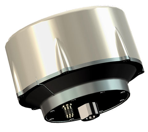
Tallysman, a manufacturer of high-performance GNSS antennas, announces the commercial availability of the VeraPhase 6000 antenna series, a family of antennas that provides the lowest axial ratios (horizon to horizon, through all azimuths) across all GNSS frequencies (70 percent), a tight PCV (± 1mm through all frequencies, azimuths, and elevations), and a consistent PCO through all frequencies.
The performance of the VeraPhase rivals that of choke ring antennas, but is much lighter, smaller and more economical, Tallysman said. The antenna family is designed for use in survey, precision RTK and reference antenna applications.
The VeraPhase 6000 also provides an available PCB within the base of the antenna for integration of a custom system board such as a dual-band or RTK GNSS receivers or other applications.
The VP6000 family provides high receive RHCP gain over the full GNSS spectrum:
low GNSS band (1164 MHz to 1300 MHz)
L-band correction services (1525 MHz to 1559 MHz)
high GNSS band (1559 MHz to 1610 MHz).
Each model features a robust, high IP3, pre-filtered LNA to minimize desensing from high-level out-of-band signals, including 700 MHz LTE, and that yet still provides a noise figure of less than 2.5 dB. Non-pre-filtered versions are also available with a noise figure of less than 1.5 dB.
The VP6000 antenna family is available in three formats:
A survey-grade all-band antenna that provides 35-dB LNA gain and is available with a robust rubber bumper for field use.
An all-band base station antenna is available with 35-dB LNA gain or with an internal 15-dB pre-filtered pre-amp for OEM applications.
An all-band reference antenna that features a 50-dB gain LNA, a conical radome to shed snow ice and birds, and is available with a robust monument mount for sub-millimeter precision.
Each antenna has a well defined phase centre offset relative to the antenna reference plane.
The base housing of the VP6000 is IP67-compliant and weighs less than 700 grams. The antenna is 167 millimeters wide at the top, 110 millimeters wide at the base and 110 millimeters in height. Each model has a 5/8-inch x 11 TPI thread for mounting and is available with either a TNC or an N-type connector.
The AL3RT asset tracker is designed for the power sports industry and runs on the AT&T network.
Kika Enterprises announced at CTIA Super Mobility this week that its AL3RT asset protection unit will be available as an accessory for Polaris electric bikes worldwide, beginning January 2016. The AL3RT trackers will be sold at sports dealerships in the United States.
Powered by AT&T, AL3RT is a stand-alone, customizable asset locator and fleet management tool designed for theft protection of on- and off-road vehicles, motorcycles, snowmobiles and personal watercraft.
AL3RT customer benefits include: real-time location alerts, anti-theft alerts, accident panic alerts, historical location data, coverage in locations around the globe, long battery life (up to seven days) and a water- and dust-proof housing. The product line will also include several accessories, such as a multi-use cradle for easy mounting and Bluetooth multi-sensors that can be programmed individually.
Supported by GPS, GSM, Wi-Fi and Bluetooth technologies, users can use their AL3RT smartphone app to locate their asset, as well as arm and disarm sensors and configure geofences virtually anywhere in the world. AL3RT can be configured to send individual or group alerts via email or SMS.
“We are excited about the launch of the AL3RT, because it represents the first true anti-theft alert solution designed for the power sports industry,” commented Ricardo Salguero, president of Kika M2M. “The AL3RT offers superior features, reliability and AT&T connectivity, making it a tremendous extension of our growing line of customizable M2M solutions. This addition truly positions Kika M2M uniquely in the market with a broad range of proprietary M2M solutions for the power sports industry.”
Kika M2M will showcase the AL3RT at CTIA Super Mobility, taking place Sept. 9-11 in Las Vegas, as a part of AT&T’s Booth #3724.
UPDATE (9/10/15): A public workshop will be held in Washington, D.C., on Oct. 2 to provide an opportunity to discuss the draft test plan and address questions before the close of the public comment period. The workshop will be held in the RTCA NBAA/Colson Room, 1150 18th St. NW, Suite 910, Washington, D.C., 20036. Click here to register for the workshop.
The U.S. Department of Transportation today published a Federal Register Notice seeking public comment on a draft test plan for the GPS Adjacent Band Compatibility Assessment effort. The plan aims to obtain interference tolerance masks for GNSS receivers in the L1 radiofrequency band (1559-1610 MHz).
The objective of the test is to collect data to determine Interference Tolerance Masks (ITM) for categories of GPS and GNSS receivers processing signals in the 1559-1610 MHz Radionavigation Satellite Service (RNSS) frequency band, as well as receivers that process Mobile Satellite Service (MSS) signals to receive differential corrections.
Demand for commercial spectrum to support broadband wireless communications — in particular, LightSquared — has led the government to consider repurposing various radio frequencies, including the satellite communications bands next to GPS. The ITMs will be used to assess the adjacent band interference power levels that can be tolerated by GNSS receivers processing desired signals in the RNSS band.
The document outlines the requirements, the overall test plan, and the associated output data needed to successfully perform this component of the GPS Adjacent Band Compatibility assessment.
The plan can be downloaded here. Deadline for comments is Oct. 9.
In December 2012, the DOT developed its GPS Adjacent Band Compatibility Assessment Plan that identifies the processes to:
Derive adjacent-band transmitter power limit criteria for assumed new applications necessary to ensure continued operation of GPS services, and
determine similar levels for future GPS receivers utilizing modernized GPS and interoperable GNSS signals.
The DOT has previously held three public workshops to discuss the Adjacent Band Compatibility Assessment.
The new version of the precise point positioning software includes several updates and new features, including creation of GAPS Basic and Advanced user submission pages.
The GAPS Basic user submission page allows for quick and easy submission of observation files for users who frequently use GAPS’ default processing options.
The GAPS Advanced user submission page includes:
• User-selection of the orbit and clock products to be used.
• User-selection of the carrier-phase and pseudorange observables to be used.
• Optional use of GPS L2C in place of P2 for all satellites currently transmitting L2C.
• Optional use of GPS L5 in place of L2 for all satellites currently transmitting L5.
• Optional use of static-mode satellite clock interpolation (if 30s clock product is used and logging interval < 30s).
• User-selection of GDOP cut-off threshold.
• User-selection of positional convergence condition and maximum number of iterations for least-squares filter.
• Enhanced the cycle-slip detection algorithm (following Blewitt, 1990).
• A minimum of 4 satellites per epoch are required before estimation begins.
• User-selection of all available neutral atmosphere delay (NAD) prediction model and mapping function (MF) combinations.
NAD prediction models include: UNB-VMF1 (NCEP), UNB-VMF1 (CMC), VMF1 (ECMWF), UNB3m, GPT2 (1×1 deg.), ESA 2.5 and None
Mapping function options are: Vienna MF and Niell MF.
• User option to not estimate NAD.
• User option to not estimate tropospheric gradients.
• Optional use of a user-provided receiver antenna calibration file.
• NAD estimation automatically terminated if receiver rises above neutral atmosphere threshold (50,000 ft = 15,240 m).
• Added option to estimate precipitable water (if a meteorological file is submitted).
• New .ion, .cmp, .nad, and .DOP output files as well as modified formatting of the .par file.
• Improved reporting of processing parameter options and results in the HTML output.
• Added receiver clock and DOP plots.
• Added height component to kml output.
For information on the processing strategy, visit the web page. Your feedback (suggestions, bug reports, etc.) is welcome via the GAPS Development Team email: [email protected].
TESSCO Technologies is introducing a low-cost investment vehicle tracking, monitoring and control solution at CTIA Super Mobility, being held Sept. 9-11 in Las Vegas. TESSCO is a provider of the product and value-chain solutions required to build, use and maintain wireless systems. The company is displaying the fleet management solution at booth 5932.
“Spending in the U.S. logistics and transportation industry totaled $1.33 trillion in 2012. However, fleet management systems have remained largely disjointed and costly for smaller fleets. Our Fleet Management Solution provides choice, convenience, best-in-class products and a total source for all of the elements needed to deploy a management solution faster and at the lowest cost investment,” said Steven Tom, TESSCO VP of Analytics, Innovation & Learning. “We provide the expertise and service built on our deep experience in wireless networks and in-vehicle communications. We deliver the end-to-end products and services including sensors, telematics, vehicle mounts and internet connectivity.”
Join Steven Tom for his presentation “The Road Ahead: The Future of Fleet Management and Telematics” on the Networked Society & Startup Stage at 2:30 p.m. on Wednesday, Sept. 9. He will share details about the new product offering as well as look ahead to the future of fleet management.
There I was, well above Angels 40, sound asleep wearing a positive pressure oxygen mask and helmet with the droning of multiple jet engines in the background for company. Then, I was abruptly awoken by an aircrew member urgently calling my name.
On waking I noticed that it was colder and darker than I remembered when I had nodded off. The only light was that strange ambient light you only experience at high altitudes, and there was zero radio chatter in my helmet headset.
When I reached the cockpit, I noticed the ambient light again because the radar screens were blank, as were all the electronic screens for our multiple sensors, and then it dawned on me. There had been some kind of an electrical failure. I glanced at the navigation displays to determine our position, and to my dismay, discovered they were all blank and lifeless as well. This should not have been, as all navigation and emergency avionics instruments had extensive battery backups.
Then I looked closer and noticed that not only were the screens blank, but the inertial power switches were in the standby position. All kinds of thoughts raced through my mind as the pilot-in-command, easily 20 years my senior (we will call him Bill for brevity) explained that after the fifth and last over-water air refueling things were progressing nominally — until they weren’t. Suddenly, amber and yellow caution lights appeared, followed quickly by red warning lights, all of which warned of imminent power failures of the jet-engine-driven generators. The special mission aircraft we were flying had enormous generators on all engines, so large they precluded thrust reversers on any of the engines. The aircraft needed all that power to function as a mission aircraft, but fortunately needed no electrical power to remain airborne.
We completed the “total loss of electrical power” checklist, and for the time being all was well. The copilot calculated the aircraft could fly for another 10+ hours with IFR reserves using the fuel on board, and from our high altitude could “glide” with engines at idle for a couple hundred miles. So, no worries right?, as one of our Australian exchange pilots liked to say. Of course, there were several worries, the main one being no one knew exactly where we were. Like Daniel Boone we were not officially lost, just a bit bewildered.
Airborne Class
Another aircrew instructor and I were onboard this particular aircraft enroute to what must remain an undisclosed location down under, to teach a class and develop a curriculum on overwater navigation for crews flying reconnaissance aircraft. My apologies for the brevity, but that is all I am allowed to say about the aircraft and our mission to this day.
The aircraft had every bell and whistle you can imagine and then some, but it was essentially an electric aircraft as far as mission and navigation were concerned, and at the moment we were fresh out of that commodity. My instructor colleague and I were about to give out first impromptu overwater navigation class at altitude. We were not yet in extremis, but if we did not do everything exactly right, it might be everyone’s last overwater navigation class.
Back to Basics by Necessity
I had one of my flight bags with basic navigation gear with me on the flight deck and not stowed in the cargo hold, which was not accessible in flight. In that bag I had protractors, rulers, various conversion tables including the critical Aeronautical Almanac and Sight Reduction Tables for Air Navigation, plus an antique but serviceable sextant. The sextant needed to be treated with kid gloves, which is why I had the bag with me rather than stowed in the baggage compartment.
Sextant courtesy of Landfall navigation.
My colleague and I suggested that as an augmented crew, we run through the emergency checklist for total loss of electrical power once again. Then we reviewed the Dash One (aircraft bible) on electrical failures and recommended actions plus all the flight crew actions 30 minutes prior to the power failure. We checked circuit breakers throughout the aircraft including in the mission compartment, the avionics and the mission equipment bays. We found nothing amiss except a plethora of red warning lights that told us nothing new; we were literally in the dark.
The good news was that aerodynamically the aircraft was performing perfectly. Considerable experience with the persnickety nature of emergencies and aircraft electrical systems precluded making any drastic changes. The autopilot was off and the aircrew was hand-flying the aircraft that, when perfectly trimmed, actually required very little effort. That was good, since under even the best scenario we were “feet wet” — over water for at least another seven hours.
Just before the massive electrical failure, the navigator calculated the aircraft was passing the “go-no-go equidistant” point of flight, which on long overwater flights means the aircraft, under nominal conditions and considering the prevailing wind and drift, could proceed to the landing destination but no longer had fuel or endurance to return to a suitable airport nearest the original “feet wet” departure point. In other words, we only had enough fuel to continue to our destination and could not turn around and return to another suitable airport to land. Plus, deviating from our scheduled route and flight plan without being able to notify the flight-following stations meant that if we ditched, no one would be looking for us in the right location. Additionally, politically the number of foreign airports where we could land our type of reconnaissance aircraft were few and far between. We elected to proceed to our original destination.
This was not a democratic process or decision, as the pilot-in-command always has the last say. He is ultimately responsible for the aircraft and crew. But we were all in the same predicament, so after we had each voiced our opinions, the aircraft commander made the correct decision to proceed and to change the aircraft configuration as minimally as possible. This meant we would not try to bring the generators back online until we were over land and within gliding distance of a suitable airport, which by our best guess was seven hours distant.
The aircraft had a RAT, or ram air turbine, for just such emergencies, except that it was not for this emergency. RATs are typically used for short durations, generating power to make emergency radio calls. Once deployed, a RAT could not reliably be re-stowed, and there was no record of anyone having deployed a RAT for more than seven hours. Plus, it would probably affect the handling of the aircraft. No one knew exactly how nor how much drag it would produce, and how it would affect our endurance or emergency glide capabilities. Best to leave the RAT stowed for now. If the engine generators and bus did not come back online once we were over or near land, then we would consider deploying it and making emergency radio contact. While being out of radio contact was not unusual for our type of aircraft, the FAA and its equivalent at our destination would probably be the agencies initially concerned. As a last resort, our parachutes all had survival radios that could be utilized for communications on guard channel — presuming someone was monitoring guard and heard our call.
Older Is Not Necessarily Better
We were straight and level on a heading for our destination, determined from the original flight plan and from weather and atmospheric data more than 48 hours old. We needed real-time or as close to zero age of data as we could manage, and it would have to be generated internally.
The aircrew was a senior crew, but rarely flew over water out of sight of land or out of range of electronic navigation aids. The aircrew was, to put it politely, on average nearly twice the age of my colleague and I, who were qualified overwater aircrew instructors. The aircraft commander was still ultimately in charge, but his comment or charge to us was, “OK guys, you’re the experts, now what?”
Status Quo
As far as arriving at our destination, if the engines continued to run and we continued on this course, without encountering or having to deviate blindly around significant weather, we would eventually make land fall feet dry. We would then hopefully extend the RAT, make radio contact, and explain our predicament to ground control or the country’s Air Defense fighters scrambled to intercept us for violating their Air Defense Identification Zone (ADIZ) without the proper radio calls. This is where the handheld radios in our parachutes would come in handy, explaining on guard channel to the fighter/interceptor pilots that we were allies and good guys and just experiencing a communications failure. All of which would be embarrassing and potentially fraught with dangerous consequences, but which could be avoided if the power miraculously came back on or if we followed the emergency “communication out” ADIZ penetration procedures for that particular country.
These emergency procedures, while almost global in nature, were well known in theory but rarely, if ever, practiced by flight crews. They consisted of: flying within a prescribed 10-mile wide corridor, arriving at the ADIZ penetration point on course and on time, and then flying a specific triangular pattern for three consecutive iterations, while listening on guard, if possible, and then proceeding to our original destination as planned, possibly still “comm out,” flying a communications out, VFR (visual) approach and landing as planned. Such an arrival might create a minor stir, but we would be seen as obeying the international flight rules and hopefully no one would be chastised or court-martialed.
Do We Have a What?
To accurately fly the ADIZ penetration procedures, we needed to know where we were, how fast we were flying (our groundspeed), and what factors were affecting our flight planned heading. Since it was still daylight, our best bet was to use “back to basics” navigation techniques to determine our groundspeed, and then as the stars appeared, we could better determine our position and refine our heading.
The crew regarded me with some skepticism as they realized I intended to use an old-fashioned sextant to determine the speed and heading and then navigate a multi-hundred-million-dollar modern reconnaissance aircraft. An aircraft with multiple Doppler receivers, inertial navigators, pinpoint radars, satellite communications, racks for a GPS receiver that had yet to be installed and an avionics suite that was second to none at the time. I proposed we navigate for seven hours with an obviously antique handheld brass sextant that I pulled carefully out of a velvet pouch stowed in my flight bag. And I would have done just that, if I had not realized that this aircraft also had a sextant port when the flight engineer mumbled something about a dusty old sextant case being strapped down in the avionics bay.
Within minutes, the old sextant case was opened to reveal a pristine sextant still wrapped in depot preservatives. It may have literally never been used since it was put on the aircraft, probably as a safety afterthought. Certainly no one on the crew had ever used one on this aircraft, and the senior navigator had not used one since navigator school at Mather Air Force Base in California. Since there was no electrical power, we were not sure the sextant would work or if the displays would be readable. After checking it over, we pushed it through the sextant port and were rewarded with a good pressure seal. We found a spare D-cell battery to power the sextant in emergency mode, hooked up that cable and were in business. General Curtis LeMay would have been proud.
Non-Traditional Navigation Sensors
For those of you not familiar with celestial navigation, or using a sextant with the accompanying Air Almanac Star Reduction Tables (remember, the Sun is a star) basically it goes something like this:
“Celestial navigation is the ancient art and science of position fixing that enables a navigator to navigate without relying on dead reckoning, to determine their position. Celestial navigation uses ‘sights,’ which are angular measurements taken between a celestial body and the visible or artificial horizon. The sun is most commonly used, but navigators also use the moon, a planet or one of 57 other navigational stars whose coordinates are tabulated in the Nautical and Air Almanac.
“Celestial navigation sights locate one’s position on or above the Earth. At a given time, any celestial body is located directly over one point on the Earth’s surface. The latitude and longitude of that point is known as the celestial body’s geographic position (GP) or sub-point, which can be determined from tables in the Air Almanac.
“The measured angle between the celestial body and the visible or artificial horizon is directly related to the distance between the celestial body’s GP or sub-point and the observer’s position. After some computational sight reductions, this measurement is used to plot a line of position (LOP) on a navigational chart, the observer’s position being somewhere on that line. Most navigators use sights of three to five stars and plot the resulting LOP(s) to minimize the chance for error.”
To begin the process, we needed to know time as exactly as possible, the date where we were located, our altitude and, if possible, an approximation of our location and direction of flight. All that information is provide by crewmember timepieces and basic navigation instruments that don’t rely on electrical power. You enter the tables and complete the pre-computation worksheet with the derived data, which you dial manually into the collimators of the sextant. Then with our bubble sextant representing the horizon, you place the Sun in the middle of the bubble and collimate on it for two minutes, read the resulting number off the sextant, convert it to a distance from the celestial bodies’ known sub-point, and that is your LOP. Since we were traveling in a southwesterly direction, the Sun provided a speed or velocity LOP. It would not determine our location with any certainty, but would provide a reliable estimation of our speed over the Earth.
We knew our basic air speed from the onboard instruments that were still working, but we needed to know our ground speed, which is affected by head, tail or cross winds. Two such Sun sightings over a period of 10 minutes multiplied by 6 gave us our ground speed, and when compared to our airspeed told us that we had a 40-knot tailwind, likely due to a forecast large low-pressure system behind us. Consequently, we would be drifting to the left, which would cause us to steer right a few degrees of our intended course, since the planned tail wind was only 20 knots, not 40. Now we knew our groundspeed and refined our ETA (estimated time of arrival) at the ADIZ penetration point. We conducted Sun shots and calculations every 30 minutes until the Sun set and the stars were visible. Shooting and plotting multiple stars for positions is just a bit more complicated and time consuming, but because it results in an actual position, rather than a speed line, it is much more valuable.
We had additional sources of data as well, which surprised the senior crew — whom we were essentially instructing in the basics of emergency overwater navigation. We plotted the best dead-reckoning line of position based on the flight plan and last known position. Then we plotted several more lines of position based on temperature, ground speed and pressure readings. This is a technique rarely used by navigators today, but one that helps you double-check your assumptions and flight planning data. In the Northern Hemisphere, a low pressure system behind you when heading southwesterly will nominally result in a tailwind and drift to the left of your course, based on the old mnemonic high up right and low down left, just as longitude and latitude mathematical values are based on the mnemonic East is least (minus) and West is best (plus). Similarly, if the temperature is rising over time, then you are most likely drifting to the right. If it decreases, you are likely drifting to the left. Lows are typically cooler than highs. If the barometric pressure is rising, then you are drifting right, and if it lowers, then you are drifting left. These are not all hard and fast rules — you can be on the backside of a major weather system and experience all these phenomenon — but if you are not being tossed about in the middle of a major thunderstorm, these mnemonics can save your life.
Normally a navigator will take one sextant shot per hour while averaging wind, pressure and temperature data over the same time. Given our dire circumstances, we calculated pre-comps and shot planets and stars continuously, on the average of three sights per hour, and took temperature and pressure readings every 10 minutes for the next 7 hours. Arriving at the ADIZ penetration point, we flew our three triangular patterns and were shortly thereafter intercepted by a Canberra aircraft that was conveniently in the area (it turns out our hosts had been expecting us and determined from the radio silence that something was amiss). The Canberra pilot informed us on guard channel (those wonderful parachute radios proved a godsend) that he would lead us to our destination. Thankfully, the weather was VFR (visual flight rules). We followed him down on a visual approach to our destination, and when he broke off in the pattern, we landed uneventfully.
We attempted to bring the engine generators online 30 minutes before the predicted ADIZ point without success. However, in the process the battery connections were re-energized and the inertial devices woke up. Because an airborne initialization required more than an hour’s time, we used them as a groundspeed reference only. Frankly, all the warning messages and flashing lights in the otherwise dark cockpit were almost more of a distraction than help.
Debrief
During the mission debrief, the maintenance crews informed us that a faulty sensor and a computer glitch had caused the power problems. Our generators were fine, but the faulty sensor and computer software had combined to shut down all generators.
Lessons Learned
Looking back on this flight many years later, in retrospect I believe we made all the right decisions. We continued to our destination and did not attempt to fix a major problem over water as long as the basic airframe and engines were doing their job. We followed our flight plan, and if we had ditched, we would have hopefully been found along our route of planned flight.
We made use of the instruments and crew-member capabilities on hand. We used a navigation method vetted over literally hundreds of years with the most modern versions of that equipment available. The crew learned how to use basic data almost always available on any aircraft, powered or not, to lay down not one but multiple lines of position.
Today, if the same scenario came about, the basic decisions would be the same, except that crew members would merely pull out their pocket GPS navigation devices, probably mostly iPhones, and using a power-saving battery plan, navigate their way to their destination. The difference is that the data — weather, groundspeed, altitude, heading and ETA, even to various waypoints — would be instantly available, and it would be accurate to within feet and nanoseconds, not miles and minutes. They might even have been able to call ahead.
Inertial Inertia
Contrary to what some in the Defense Department have been saying, the inertial devices onboard would have been just as ineffective if this scenario was repeated today. The critical and operational limiting caveats that most laymen and even some military users miss about individual inertial devices is that they are intrinsically dumb devices that experience drift and bias phenomena that are not always predictable. Inertial units do not know when or where they are until they are told. Even after they are told, if the inertial units lose power without a battery backup, they need to be told time and time again when and where they are. GPS performs this function very well, and together the two systems are almost the perfect navigation combination.
Without an internal clock and coordinate system (chip-scale atomic clocks [CSAC] will work only after they are initialized and told what time it is, a function more often than not performed by GPS today and in the foreseeable future), an inertial device will not show you where you are on a map display or in any discernible or chartable coordinates. An inertial device, while it is superbly equipped to measure movement in every axis, is basically a three-dimensional device. Inertial units detect up from down, left from right, and acceleration or de-acceleration, but they do not detect changes in time or know their starting, way or endpoints in discernible coordinates without being told. So, yes, Mr. Secretary, it would be great to have an inertial that would run for a thousand years, but first you need the miniaturized atomic reference systems, power systems and coordinate determination systems that will run that long as well.
In other words, we need an inertial system that is a system of systems, which today are ideally comprised of CSAC and GPS devices with a laser gyro. In the not too distant future, a cold atom interferometer MEMS (microelectromechanical system) inertial with CSAC and GPS all backed up by eLORAN is probable. That, however, is a story for another time.
Until next time, wax nostalgic — dig out your old sextant and take a sighting. Until then, happy navigating, and remember that GPS is brought to you courtesy of the United States Air Force.
GPS World reports live from CTIA Super Mobility 2015 in Las Vegas Sept. 8-11, organized by CTIA—The Wireless Association. The Western Hemisphere’s largest mobile innovation summit brings together 35,000 professionals who work in the mobile technology industry, including leaders in wireless, indoor location, connected car and Internet of Things (IoT), among many others.
GPS World digital editor Bethany Chambers and Wireless editor Janice Partyka will be reporting all week here on GPSWorld.com, on Facebook and on Twitter @GPSWorld. This convention is far from conventional in its use of multimedia to fuel the excitement surrounding all things mobile; the show has an official DJ in Los Angeles-based Bella Foxx and an emcee in Saturday Night Live’s Michael Che. Keynotes also follow the multimedia theme this year, with DreamWorks CEO & cofounder Jeffrey Katzenberg, Wikipedia founder Michael Wales and iHeartMedia Chairman Bob Pittman scheduled to appear.
GPS World talks to Taoglas VP of North American Sales Tim Dolan on the show floor in Las Vegas about the Storm Antenna. He explains what makes it unique to the market–and what comes next.
TeleCommunication Systems Inc. Senior Vice President of Commercial Solutions Jay Whitehurst introduces VirtuMedix at CTIA Super Mobility 2015. The telemedicine solution utilizes location-based services to connect patients with clinicians in their area.
Olivier Pauzet, vice president of marketing and market strategy at Sierra Wireless, details AirVantage connectivity services for fleet tracking and the recent addition of Google cloud integration.
Jorge Pineda, vice president of sales for Queclink Wireless Solutions, shares information on the company’s U.S. and international sales plans for 2015 and beyond, with a focus on fleet tracking and global LTE expansion.
Parsec Technologies CEO Michael Neenan introduces the company’s LTE/GPS antenna. The antenna, which you can find out more about at parsec-t.com, is already in production and available for sale, and Neenan previews how the antenna will be used further in a watch coming out later this year. Find out more about the Texas-based company’s antenna, touted for its flexibility and interoperability.
Janet Jaiswal, vice president of enterprise marketing, and Gurinder Dhillon, senior director of Internet of Things (IoT) platforms and analytics, demonstrate how AerCloud and AerVoyance work together to enable rapid development, deployment and monitoring of IoT solutions.
The latest variant of the Excalibur precision-guided projectile will be used by armies and be available for naval ships.
The Netherlands Ministry of Defense is adding Raytheon Company’s Excalibur Ib artillery rounds to its arsenal under a previously announced foreign military sales agreement, underscoring growing international interest in the precision-guided projectile.
The Netherlands is the second Excalibur lb customer in Europe after Sweden, the U.S. government’s development partner for the 155-mm round. Deliveries are expected to begin later this year.
“The Netherlands joins a growing list of nations acquiring this highly sophisticated artillery munition, which uses GPS guidance to provide accurate, first-round effects capability at extended ranges,” said Mark Hokeness, Raytheon’s Excalibur program director. “When fired from the Dutch PzH 2000 artillery system, Excalibur can fly up to 50 kilometers, score a direct hit and deliver lethal effects in all types of weather and battlefield conditions.”
A Dutch Panzerhaubitze 2000 (PzH 2000) fires a round in Afghanistan. (Image courtesy Dutch Ministry of Defense)
The U.S. Army has determined Excalibur Ib is fully compatible with the PzH 2000, a self-propelled howitzer produced in Germany and fielded by several nations.
The Excalibur precision-guided, extended-range projectile uses GPS guidance to provide accurate, first-round-effects capability in any environment. Excalibur’s level of precision delivers a major reduction in the time, cost and logistical burden associated with using other artillery munitions. Excalibur has been fielded by the U.S. Army, Marines and several international military forces.
Excalibur Facts
Combat-proven: Nearly 770 Excalibur rounds have been fired in combat with exceptional accuracy and lethality.
Precise: Excalibur consistently strikes less than two meters from a precisely-located target, Raytheon said.
Safe: Excalibur’s precision avoids collateral damage and has been employed within 75 meters of supported troops.
Affordable: With its first round effects, Excalibur reduces total mission cost and time and the user’s logistics burden, according to Raytheon.
Evolving: Raytheon has demonstrated a dual-mode GPS/semi-active laser seeker Excalibur variant to compensate for target location error, maintain precision in GPS denied or degraded environments, and enable engagement of relocated or moving targets.
Navies: With Excalibur N5, navies will be able to deliver extended range, precision naval surface fires from existing 5-inch/127-mm guns.
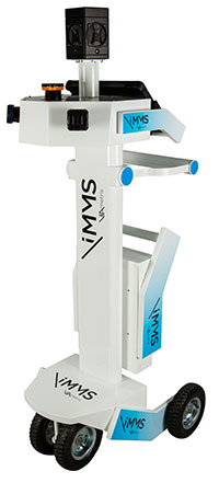
The iMS 3D indoor mapping system by Viametris uses an Ellipse-A by SBG for roll and pitch data.
SBG Systems will join Viametris in presenting a new 3D indoor scanning system at the INTERGEO trade show, which will be held Sept. 15-17 in Stuttgart, Germany.
The iMS 3D is a mobile 3D indoor scanner generating continuous point clouds. For this brand-new model of indoor mobile mapping system, or iMMS, Viametris chose SBG Systems’ miniature Attitude and Heading Reference Sensor (AHRS), the Ellipse-A. The iMS 3D is easier to transport, install and set up than previous iMMS. The iMS 3D also integrates new sensors, including the Ellipse-A from SBG Systems.
Based on the SLAM technology, the iMS 3D is equipped with three lidar profilers, each taking 40,000 points per second. The main lidar provides the horizontal profile, which also contributes to the continuous calculation of the iMS 3D position in the building. Two lateral lidars give vertical profiles, including the ceiling. While the user walks, pushing the iMS 3D at normal speed, the 3D profile of the room appears on the screen, since the system records 3D measurements of the same room. Easy to manipulate, one person is enough to survey every corner of the building with the iMS 3D.
During the survey, the 360-degree camera takes a spherical picture every two meters for a full documentation of the building. This solution makes indoor survey 10 times quicker than traditional methods usually using distance meters, Viametris said, adding that the iMS 3D delivers a combination of point density, acquisition speed and accuracy suitable for the building trade industry.
At the office, the user accesses a centimeter-level accuracy 3D survey as a point cloud and pictures by using the Viametris processing and browsing software. The user can import the point cloud in CAD software (Autodesk Revit, AutoCAD, MicroStation, Rhino, etc.) to easily produce 2D maps or 3D models. The point cloud can be colorized with the colors of the pictures taken during the survey, which greatly improves the environment understanding. Additionally, the user has access to contextual 360-degree pictures, making objects such as radiators, extinguishers or lights simple to distinguish and locate.
Ellipse-A.
Already integrated in other Viametris ultraportable technologies, the Ellipse-A has been chosen for this new generation of indoor mobile mapping system, or iMMS. “We integrated an Ellipse-A in our 2D system and were very happy with the results. It was obvious to us that the Ellipse-A will be part of our new iMMS,” said Jérôme Ninot, president of Viametris. The Ellipse-A is used to correct the horizontal profile. While the user is pushing the iMS 3D through the rooms, unevenness, slopes and ramps, cables or door thresholds can cause noise in the point cloud. The Ellipse-A keeps the point cloud clean by correcting the horizontal lidar data frames used to build the trajectory.
The Ellipse-A AHRS provides roll and pitch data accurate to 0.2° at 200 Hz. “The Ellipse sensors are much more efficient than the previous IG-500 product line,” said Mr. Ninot.
Keeping lidar and camera data precisely synchronized can be difficult because the camera focal time is susceptible to vary. In mobile scanning, even a slight latency might cause an offset. For example, the picture will not be located on the right place inside the point cloud. Viametris decided to connect the camera and the three lidars to the Ellipse-A to ensure a highly accurate and repeatable synchronization.
At INTERGEO 2015, the iMS 3D will be presented at stand # B4.049 and the ELLIPSE-A will be presented at stand # G4.079.
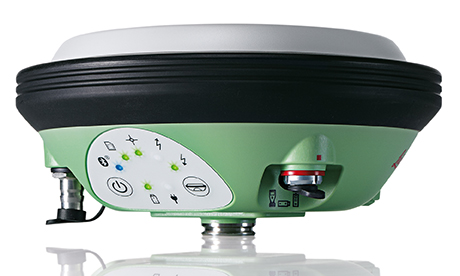
Leica Geosystems, manufacturer of the Leica Viva GNSS Unlimited series and GS14 GNSS receiver, has added a new hybrid communication technology to its compact and powerful GNSS smart antenna. The latest generation Leica Viva GS14 GNSS now supports Verizon CDMA solutions along with all standard 2G/3G networks and UHF TX/RX radio in a single device, making it a professional GNSS receiver with all three communication systems built in. Users simply slide in their SIM card to experience instant connectivity for faster and easier field communications and SmartNet RTK corrections, the company said.
The Leica Viva GS14 3.75G&UHF supports 2G GPRS, 3G HSPa+, CDMA (EV DO) and UHF TX/RX radio between 450 and 470 MHz in one compact housing. Professionals can choose whether they want to use the UHF radio to transmit or receive work, a 2G/3G cellular network, or Verizon CDMA. No external equipment is required.
“The Leica Viva GS14 with its hybrid communication technology is the most advanced compact GNSS receiver in the market,” said Bernhard Richter, Leica Geosystems GNSS business director. “The addition of CDMA modem capability in a unique all-in-one design offers unmatched flexibility in communication choices.”
The Leica Viva GS14 3.75G&UHF is available today throughout the United States. Ordering information and details are available from all authorized U.S. Leica Geosystems representatives and dealers.
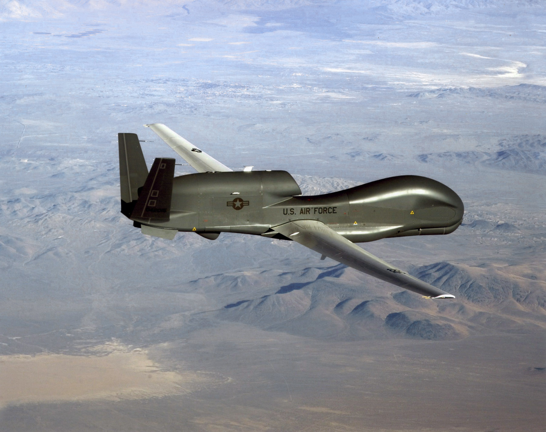
An RQ-4 Global Hawk soars through the sky to record intelligence, surveillence and reconnaissance data. (Courtesy USAF)
Curtiss-Wright Corporation’s Defense Solutions division was honored by Northrop Grumman for its role as a supplier in support of the RQ-4 Global Hawk unmanned aircraft system (UAS).
Global Hawk has flown 150,000 total flight hours supporting diverse global missions. Carrying a variety of intelligence, surveillance and reconnaissance sensor payloads, Global Hawk supports anti-terrorism, humanitarian assistance, disaster relief, airborne communications and information-sharing missions.
A ceremony was held Aug. 19 at Curtiss-Wright’s Integrated Systems facility in Santa Clarita, Calif., for the program to receive the James G. Roche Sustainment Excellence Award for a third year in a row. During the ceremony, an award was presented by Mick Jaggers, Global Hawk UAS vice president and program manager, Northrop Grumman Aerospace Sector, and accepted by Lynn Bamford, senior vice president and general manager, Defense Solutions division. The event was also attended by Rep. Steve Knight, U.S. Congressman for California’s 25th District.
(From left) Knight, Bamford and Jaggers with the award.
“We extend our sincerest congratulations to the US Air Force on this award and Northrop Grumman for their stellar job as the prime contractor on the milestone setting RQ-4 Global Hawk UAS,” said Ms. Bamford. “We take great pride in Curtiss-Wright’s role as an industry leader in providing advanced rugged electronics that help lower this important aircraft’s cost through the use of commercial-off-the-shelf technologies.”
During the ceremony, Jaggers remarked, “An aircraft as sophisticated as the Global Hawk comes together with the help of many partners, and one of the most crucial sustainment partners on the Global Hawk is Curtiss-Wright.”
The Sustainment Excellence Award is granted by Headquarters U.S. Air Force Logistics, Installations and Mission Support. It is named for Dr. James G. Roche, the 20th Secretary of the Air Force, a position he held from 2001 to 2005.