Most railroads will miss the Dec. 31, 2015, deadline for implementing positive train control (PTC), according to a report submitted to the U.S. Congress by the Federal Railroad Administration (FRA). Congress established the deadline in 2008.
An automatic train control system — many of which use GPS — was not installed on the commuter rail route where an Amtrak train left the track in May.
The FRA sent its “Status of Positive Train Control Implementation” report to Congress this week. The report is mandated by the House of Representatives Appropriations Committee.
“Positive train control is the most significant advancement in rail safety technology in more than a century,” U.S. Transportation Secretary Anthony Foxx said. “Simply put: it prevents accidents and saves lives, which is exactly what we seek to do at the Department of Transportation every single day. We will continue to do everything in our power to help railroads install this technology.”
The National Transportation Safety Board (NTSB) began calling for train control systems like PTC in 1969, and the FRA was involved in establishing PTC standards with stakeholders for more than a decade before the 2008 mandate. Three years before Congress passed the PTC mandate, the FRA issued its final rule that established uniform PTC standards for railroads willing to voluntarily install the technology.
Positive train control prevents train-to-train collisions, over-speed derailments, incursions into established work zone limits and a train going to the wrong track because a switch was left in the wrong position.
In 2008, Congress passed the Rail Safety Improvement Act, requiring all Class I railroads transporting poisonous-by-inhalation hazardous (PIH) or toxic-by-inhalation hazardous (TIH) materials, and all railroads providing passenger service, to implement Positive Train Control by Dec. 31, 2015.
The FRA has provided assistance and support to railroads to help them become PTC compliant. Those efforts include:
Providing more than $650 million to passenger railroads, including nearly $400 million in Recovery Act funding.
Issuing a nearly $1 billion loan to the Metropolitan Transportation Authority to implement PTC on the Long Island Rail Road and Metro-North.
Building a PTC testbed in Pueblo, Colo.
Working directly with the Federal Communications Commission and the Advisory Council on Historic Preservation to resolve issues related to spectrum use and improve the approval process for PTC communication towers.
Dedicating staff to continue work on PTC implementation in March 2010, including establishing a PTC task force.
“The Federal Railroad Administration will continue to use its resources and expertise to help railroads achieve the critical goal to have Positive Train Control implemented,” FRA Acting Administrator Sarah Feinberg said.
Finnish radio data communication specialist Satel will present innovative new products for mission-critical radio data networks at INTERGEO, being held in Stuttgart, Germany, Sept. 15-17.
In Germany, radio data communication solutions from Satel are distributed by the full-range and systems provider Welotec. At the trade fair in Stuttgart, the partners will present their products at adjacent stands. Both Satel as a radio data communication specialist and Welotec as a full-range and systems provider have a strong portfolio for the core market of RTK/GNSS, UAV and RPAS (remotely piloted aircraft systems) applications.
By 2020, Satel intends to be the world’s number one provider of mission-critical data connections, it said in a statement. This goal also includes becoming the technology leader, which the company hopes to achieve through intensified research and development.
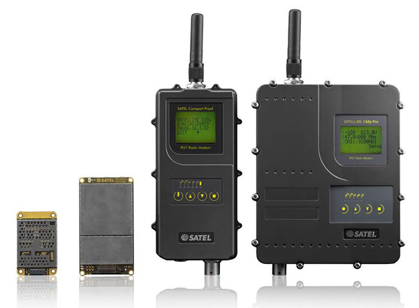
At INTERGEO, Satel will present its latest products. Visitors will be able to see the OEM modules Satelline-M3-TR1 and Satelline-M3-TR4. These modules allow use of the frequencies requiring a license (330 – 473 MHz) as well as the European license-free frequency ranges (433.05 – 434.79 MHz and 869.400 – 869.650 MHz).
The newly developed Satelline-M3-TR4 is the smallest available data transceiver module in its class, according to Satel. The Satel Compact-Proof is a portable radio data modem with a rechargeable battery and a flexible tuning range (403 – 473 MHz). The robust Satelline EASy Pro 25W, likewise with a broad tuning range (403 – 473 MHz), allows radio communication up to a range of 50 km, which makes it quite versatile.
Welotec offers a large range of antennas that supplement the Satel radio data modems. The antennas cover a large frequency range from 68 MHz to 6000 MHz, indoor and outdoor applications, MIMO technology and also antennas with an operating range from minus 40 degrees Celsius to 80 degrees C for use in harsh environments. At INTERGEO, visitors will see innovative solutions from Welotec in the area of industrial communication — for example, the industrial UMTS, LTE and WLAN routers of the TK800 series or the high-performance Industrial-WLAN access point DM500. For measuring tasks, Welotec offers the laser distance sensor OWTB V2.1, which features an extremely high resolution and ranges of up to 500 meters for industrial applications.
Satel and Welotec will be at INTERGEO 2015 in Stuttgart in Hall 4, Booth G4.020. GPS World is covering INTERGEO live — visit gpsworld.com and follow us on Twitter and Facebook.
Fugro has extended its integrated survey services to help improve efficiency in coastal management and enable more informed decision-making. A new agreement with global specialist EOMAP enables the creation of integrated bathymetric survey products that comprise elements from Satellite Derived Bathymetry (SDB), Airborne LiDAR Bathymetry (ALB) and traditional acoustic survey technologies. The integrated data and product solutions will provide clients with outstanding value and unmatched coverage, Fugro said.
“Teaming with EOMAP augments our considerable survey and satellite imagery capabilities and will allow a timely and cost-effective nearshore bathymetry review facility for clients whose own bathymetric holdings are either very old or very sparse — or both,” said Don Ventura, hydrographic business development manager at Fugro. “This service will help coastal zone management and engineering teams, environmental scientists and hydrographic agencies to focus on their immediate needs and to make more informed decisions on subsequent, efficient data acquisition and management.”
EOMAP’s robust technology platform can process satellite images and deliver global bathymetric and benthic habitat data over the full range of temporal and spatial resolutions through its proprietary, sensor-independent Modular Inversion Processor (MIP). This both complements and augments services already provided by Fugro, to provide even more spatial data solutions to suit a wide variety of budgets and purposes.
“We are very pleased to provide our Satellite Derived Bathymetric products and services to Fugro,” said Matthew Bergin, Vice President of Business Development at EOMAP. “We believe that this agreement will create a unique, one-stop technology resource to meet the demanding requirements of both commercial and government customers.”
Fundamental in the determination of GNSS solutions is resolving the correct number of full cycles of the carrier signal (so-called fixing ambiguities) in order to resolve the ambiguity differences between the base and the rover. Distances measured from GNSS receivers contain errors caused by inaccuracies in the satellite and receiver clocks, the satellite orbits, and by the ionosphere and troposphere. When a base station is used, these errors are nearly identical to both the rover and base station receivers when the baseline distance is short. By removing these common errors through RTK processing, centimeter-level accurate vectors can be calculated between the base station and the rover.
Multipath, the reflection of GNSS signals from nearby objects and structures, creates its own indirect measurements from the satellites to the GNSS receiver and is the most critical source of inaccuracy in precision GNSS applications. The worst case is when the receiver doesn’t see the direct signal at all, such as when satellite is behind a building but is still receiving the signal reflected off of the nearby structure. Such indirect signals are usually strong, unhelpful and misleading.
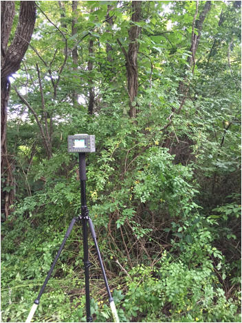
A TRIUMPH-LS collecting a point under tree canopy.
The other aspect impacting the veracity of a fixed solution is when there are weak GNSS signals. Frequently, weak signals are due to their penetration directly through tree canopy. While the TRIUMPH-LS can’t move the obstacles that are creating multipath out of the way, its sophisticated engineering is designed to handle even the weakest signals like no other system with its RTK Verification System (patent pending).
When located in difficult environments and under tree canopy, all GNSS receivers are prone to give bad fixed solutions that may appear to be acceptable if they are not verified. Existing methods to verify GNSS solutions include “dumping” the receiver, turning it upside down to cause the RTK engines to reset, and re-observing the point at a later time.
The TRIUMPH-LS automates these processes with its built-in software features of Verify and Validate. Verify automatically resets the RTK engines after every fixed epoch is collected in the first step of its process. Epochs are sorted by distance and placed into groups during the first step. Once a group has built up a set level of confidence, the RTK engines are allowed to collect the remaining epochs without resetting. If epochs fall too far away from the best selected group from the first step, they are rejected and the RTK engines are reset.
Validation is the final step of the process. With this feature enabled, the RTK engines will reset one final time at the end of the observation and collect 10 additional epochs. Allowing sufficient time between the first step and the final validation step will guarantee a bad solution is not allowed to be accepted. From extensive testing of these features in the worst of multipath environments, a bad solution has yet to be accepted when the Verify and Validate features are used and 120 epochs are collected.
After using a TRIUMPH-LS system, many land surveyors who have used other GNSS receivers in the past without preforming any type of verification are starting to realize that they may have accepted many bad fixed solutions over the years. If you are not using a receiver like the TRIUMPH-LS that has the ability to automatically reset the RTK engines and verify the results, it is essential that you manually “dump” the receiver or re-observe the point at a later time so that you don’t make this same mistake.
Are you using a legacy-model PNT (position, navigation and timing) receiver or a smart PNT receiver, and why does it matter? Don’t have a clue? Read on! Hint — L2C and CNAV (civilian navigation message format) are the major reason it matters. Yes, it’s all because of L2C, the controversial GPS civilian signal that seems to always be in the news and just keeps getting better the more we learn about it.
A couple of weeks ago, Alan Cameron, our esteemed editor in chief — penned a follow-on editorial comprised of excerpts from techies, subject-matter experts and editors, including yours truly, exchanging opinions about the flexibility, sustainability and capability of the GPS L2C signal and all that signal enables.
I won’t bother to go into the details or history of the L2C signal here, as I did that in excruciating detail 30 months ago. However, let’s consider L2C 30 months on and determine if the landscape has changed.
What is L2C?
According to the official U.S. government PNT website, “L2C is the second civilian GPS signal, designed specifically to meet commercial needs.” As it turns out, the military needs L2C as much as the civilian world, but that is a story for another time. When combined with L1 C/A (coarse acquisition signal) in a dual-frequency GNSS receiver, L2C enables ionospheric corrections, a technique that boosts accuracy. Civilians with dual-frequency GPS receivers typically enjoy the same or better accuracy as the military.
For professional and high-precision users with existing dual-frequency receivers, L2C delivers faster signal acquisition, enhanced reliability and greater operating range. L2C broadcasts at a higher effective power than the legacy L1 C/A signal, making it more jam and interference resistant, plus it’s easier to receive signals under trees and indoors. The U.S. Commerce Department estimates L2C will generate about $6 billion in economic productivity benefits through the year 2030. Considering there are more than four billion GPS users around the world today, the DOC economic benefits number seems rather low.
L2C Status
The first GPS IIR-M (R= Replenishment, M= Modernized with M-code and L2C) satellite featuring L2C launched on Sept. 26, 2005, and is still operational today. Every GPS satellite fielded since then (18 SVs, including SVN 49) has included an L2C transmitter. This equates to 16 operational L2C satellites on orbit and transmitting, with GPS IIF-10 being number 17 when it is fully commissioned. With 17 SVs (GPS satellite vehicles) on orbit, the L2C system is officially near Initial Operating Capability (IOC). With the requisite ground system upgrades, which are in the works, this means that on any given day most users will have at least one or more L2C signals in view. You can be sure manufacturers will be quick to take advantage of the geometry.
LMCO GPS IIRM Satellite Vehicle On Orbit. (Artist’s rendering courtesy of Lockheed Martin)
Legal Caveats
“In April 2014, the U.S. Air Force began broadcasting civil navigation (CNAV) messages on the L2C and L5C signals. Prior to that time, L2C and L5C provided a default message or Message Type Zero, containing no data. Adding additional CNAV message types required upgrades to the GPS control segment. On Dec. 31, 2014, the Air Force began transmitting CNAV uploads on a daily basis. L2C should continue to be considered pre-operational and should be employed at the user’s own risk.”
Now the lawyers are happy.
So What?
What does this mean for the average user? You might be surprised at the answer. Depending on how technical you are and exactly how you use GPS, it could mean that all your “legacy” GPS receivers are about to become obsolete. Or, depending on the company that builds your receivers and the amount of foresight they built in, it could just mean a few firmware upgrades and new applications.
Regardless, with the full implementation of L2C GPS signals and navigation messages, GPS will never be the same again. This is not to say your legacy receiver will not work just as efficiently as it does today, and in fact you will probably be able to use it quite effectively for years. But it will not be able to take full advantage of all the capabilities L2C enables without an upgrade, if indeed it is upgradeable.
Legacy versus Smart
No matter how much or how little you paid for your GPS/GNSS/PNT receiver, it is essentially — except for a few notable exceptions — a legacy receiver. For example Trimble is ahead of the game as they began producing L2C capable receivers as early as 2003 and are just waiting for the additional L2C messages to be defined. Again, those receivers that are not L2C-ready or capable are what I will classify as a legacy receiver, simply because of all the future capabilities that are missing. Your current PNT receiver may have the potential to be a smart receiver — it may have the technical capability to process far more than it does today. But, unfortunately, essentially almost every receiver, again with a few exceptions, on the market today falls into the “legacy ” category.
Is My Legacy Device Considered Obsolete?
Now that I have your attention and have probably riled more than a few GPS device manufacturers, please allow me to explain. In the past, your GNSS/PNT device (for brevity’s sake, I will default to PNT for the rest of the column) has basically performed a simple function. It displayed your position, and perhaps maps and other ancillary data (targets or destinations) after it received, decoded, verified and applied timing signals and a very small number of navigation messages.
It accomplished this feat typically from a cold start in under 120 seconds. Maybe much less. Recently, I was privileged to view a demonstration of a receiver from a major manufacturer that performed a warm restart in less-than-ideal conditions and displayed a useful position in 1/20th of a second. As amazing as that may be, it is still today classified as a legacy receiver. It accomplished its task; it supplied a useful position both in human and machine language that could be utilized by both. In the past, this was the task your receiver accomplished routinely. With the full implementation of L2C, all that changes and changes drastically. I call it a revolution for PNT, but alas I am frequently given to hyperbole. However, give me a moment and see if you don’t agree.
I was attracted to a Wall Street Journal headline recently by a company that I know well, since they have an abundance of well-known and multi-talented former military leaders. That company, Accenture, puts it this way: “Change is good. Transformation is even better.” That is exactly where I believe we stand today with L2C. It is a game changer.
For example, just this week in the WSJ, which I read cover to cover six days a week, I saw stories about Audi vehicles driving autonomously from coast to coast, over 3,000 miles without driver intervention. Contrary to many manufacturers, Audi is quick to credit GPS with a large portion of the proprietary Audi (VW) technology and the capability it enables. There was a story about commercial vehicles, over-the-road diesel trucks that may have even more capabilities than the Audi. Again, with GPS as the prime contributor. The same WSJ story mentioned that, “Some of the features being added to trucks are similar to those in cars, but generally the move to autonomy in commercial and industrial vehicles is far ahead of the autonomous systems offered on most passenger vehicles. Already, mining vehicles and military forklifts are operated without drivers.”
Amazingly, these capabilities depend greatly on GPS, but exist without the full implementation of the revolution that L2C, CNAV and multiple nav messages will bring.
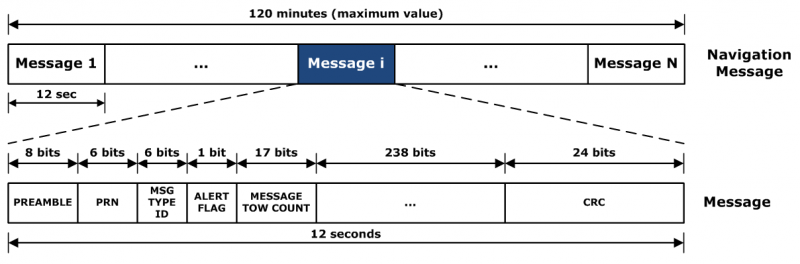
L2C CNAV Message Structure.
L2C Ready
I have over the past year seen advertisements for PNT devices that proclaim they are L2C ready. I beg to differ, but only because my definition of L2C ready probably varies greatly from that of the devices’ marketing department. Beyond its signal structure, L2C has a new messaging capability.
As stated earlier, the L2C signal is heads and shoulders above most other GNSS signals in strength, code structure and security. L2C delivers faster signal acquisition, enhanced reliability, and greater operating range. L2C broadcasts at a higher effective power than the legacy L1 C/A signal, making it interference and jam resistant and easier to receive under trees and indoors. These attributes make it a great signal and when you consider the carrier-phase and RTK (real time kinematic) capabilities, which really are real-time today. It is a very appealing signal indeed.
For precision and timing users, the carrier phase of the L2C signal, non-coded carrier, is 1,000 times more stable than the fully coded L2C signal. The L2C carrier-phase stability will remain unchanged until the semi-codeless transition date of Dec. 31, 2024, per the FRP or Federal Radio Navigation Plan of 2014. Then officially all bets are off, but who knows? That date could be extended.
However, the real and future strength of the L2C signal structure is hiding in one or more (accurately 255 more, for a total of 256) messages that can be utilized in a myriad of ways and applications. These are messages, nav-messages if you will, that your new or updated PNT device will be able to utilize for who knows how many functions. Just use your imagination. Here are some ideas I have for using the additional L2C messaging capability.
Send 250+ other navigation messages, to be defined.
Send continuous atmospheric corrections (such as ionospheric) for each two degrees of longitude around the globe or in one degree increments if you consider land mass applications only.
John Deere and Trimble as the leading commercial and civil providers of navigation data could appropriate a small fragment of the messages for their global navigation and timing corrections to their agricultural and precision users/customers around the globe.
Companies or governments could send nominal navigation or even text-based navigation-related messages to users anywhere an L2C signal can be received.
Companies could shut down and render useless receivers from users that have not paid their bills or were abusing the system.
Companies could send small firmware updates or notices of larger updates directly to users. Data could include active hyperlinks.
Precision, scientific and premium users might have the capability to receive constant correction updates that make their PNT receiver a centimeter or potentially a millimeter level device.
Receivers with communications — four billion plus smartphones and other devices with PNT capabilities and built-in communications — could become sensors capable of being sampled at will. These devices have the potential to be considered remote monitoring stations both for PNT and communications purposes. They could report both communications and PNT jamming or interference. They could also help track intentional jammers.
If you think about it hard enough, you will see that this modest list of capabilities with the proper security either make spoofing an impossibility or without proper security a malicious nightmare.
I hope by now you catch my drift and have come up with some ideas of your own concerning how the additional 250+ L2C messages could be utilized. We’re unsure how many messages will actually be available or how the messages will be used. The government will, out of operational necessity, require a small number, so right now your guess is as good as mine.
Keep in mind that L5C and M-code will have the same capabilities on differing frequencies, and different governing bodies will decide how the signals and 750-plus multiple-messaging capabilities are allocated and utilized. That is all hopefully in the near future. How that process unfolds, technically and operationally, will have a great deal to do with how successful and ubiquitous L2C becomes. The process alone will undoubtedly spawn thousands of articles; however, right now we are primarily discussing the necessity for smart receivers to fully utilize the additional L2C messages. For along with all the potential capabilities comes a processing and communications tail that does not exist today, except in a few instances that we can’t go into in this venue.
Relative
This is probably a good time to further qualify what I mean by legacy versus smart receivers. Were the appellation “legacy” not already in our vernacular concerning today’s highly functioning devices, it would not be one I would have chosen. However, it is and we are stuck with it. Consider that there are static high-end (read premium quality) single GNSS receivers that “see” more than 50-60 separate GNSS satellite vehicles and processes more than 150 GNSS signals. This does not take into consideration all the augmented and companion signals some of these devices are capable of processing. Many of these devices are very difficult to jam and literally cannot be spoofed, and still today they are legacy receivers in relationship to L2C capabilities.
However, I am told such high-end receivers are absolutely L2C ready, which may mean the additional L2C messages are ready to be processed and applied, received or rejected, whenever they are properly and officially defined. This brings us to the future definition or next generation smart L2C receiver.
Smart L2C PNT Receiver
For the first time a smart PNT L2C capable receiver will have the ability to:
Select between GPS only, GPS + GLONASS, or full GNSS mode with ancillary corrections such as WAAS and EGNOS, and work with, process or reject messages, making a decision about some or all the signals it has in view. While there are receivers that accomplish some of these functions today, they do not typically have the option of accepting or rejecting a GPS navigation message if it is properly formatted and verified. L2C smart receivers will — indeed must — at a minimum possess and correctly utilize that capability.
Alert users concerning new navigation message(s) and determine automatically or with user input whether the navigation message should be applied immediately, in the near future, put on hold or totally rejected.
Alert users to the effect that applying new or multiple navigation messages will have on the current PNT display and possibly the current mission or operation. For example, if you are a precision user, think millimeters for level of accuracy, utilizing PNT to measure tectonic plate movement — you are very interested in relative displacement over time and you may have no desire to apply a multiple nanosecond correction that could move your current measured position several inches or feet. If you are a geocacher, you do not want the coordinates of your latest buried treasure to dynamically change.
Determine if the latest valid navigation message(s) apply to your geographic area or, for mobile receivers, your destination, and what effect incorporating the messages will have on your displayed position or ETA.
Display a text-based navigation message if it is addressed to your device.
Require password(s) for certain actions — be they sensitive, proprietary, classified or of a “cannot undo” nature. Passwords could also be required in the message format before it could be unlocked and applied.
Determine and alert users if multiple navigation or device-control messages conflict with organizational or user-defined parameters.
Alert users to malicious messages or spoofing attempts.
Alert users to GNSS assets that are no longer available or go offline, such as during the two total GLONASS constellation shutdowns when GLONASS signals were not available for several hours. In the case of Apple iPhones, the GLONASS constellation-wide shutdown meant these devices went from multiple GNSS devices to “GPS plus PNT augmentation (WAAS) and other onboard sensors” devices. This is something many users may not care about, but is definitely worth a user-defined parameter for a warning message.
The ability to permanently reject a certain type of message by type, source, timeframe, etc.
By now, I hope you see the trend. You can probably think of many more possibilities for future GNSS or PNT receivers and the necessity for them to be loaded with computing and communications capabilities, especially where L2C is concerned — indeed, where all the CNAV signals and messages are concerned.
Bottom Line
The bottom line is L2C is a potentially revolutionary signal for GPS/PNT; it opens incredible opportunities for entrepreneurs, manufacturers and users at a minimum. We now all have some hard and important questions to consider before we purchase our next-generation PNT device or upgrade our legacy device.
Until next time, happy navigating, and I hope to see everyone at ION GNSS+ in September in Tampa, Fla. Remember, GPS is brought to you courtesy of the United States Air Force.
Google is reorganizing under a new name, Alphabet, separating its moneymaking businesses from its cutting-edge ventures such as the self-driving car and drone delivery service. The move is being made because Google’s penchant for experimentation made traditional investors nervous, according to the New York Times.
Alphabet would be the parent entity, housing several companies, with Google the biggest among them. Alphabet Inc. will replace Google Inc. as the publicly traded entity and all shares of Google will automatically convert into the same number of shares of Alphabet, with all of the same rights. Google will become a wholly-owned subsidiary of Alphabet.
“For Sergey and me this is a very exciting new chapter in the life of Google — the birth of Alphabet,” Larry Page, the chief executive of Google, wrote in a blog post on Monday. “We liked the name Alphabet because it means a collection of letters that represent language, one of humanity’s most important innovations, and is the core of how we index with Google search. We also like that it means alpha‑bet (Alpha is investment return above benchmark), which we strive for!””
“Sergey and I are seriously in the business of starting new things.” Page writes in the blog. “Alphabet will also include our X lab, which incubates new efforts like Wing, our drone delivery effort. We are also stoked about growing our investment arms, Ventures and Capital, as part of this new structure.”
Trimble has launched its Trimble VRS Now correction service in New Mexico. The commercial subscription service provides surveyors, civil engineers and geospatial professionals in the region with instant access to real-time kinematic (RTK) GNSS corrections without the need for a base station.
Using both the GPS and GLONASS constellations, the Trimble service delivers centimeter-level RTK corrections customized for each GNSS receiver’s location anywhere in the network via cellular communications. The Trimble VRS Now service supplies accurate, reliable and easy-to-use GNSS positioning for a variety of applications including surveying, urban planning, urban and rural construction, environmental monitoring, resource and territory management, disaster prevention and relief and scientific research, Trimble said.
“As we continue to expand our VRS Now network infrastructure throughout the U.S., users in New Mexico now have increased reliability from both GPS and GLONASS corrections to enhance their work,” said Lisa Wetherbee, business area director of Trimble’s Positioning Services Division. “Our suite of correction services offers a variety of performance options, designed to meet the different requirements and budgets of our customers. VRS Now in New Mexico delivers centimeter-level accuracy to a wide range of industry professionals.”
Service in New Mexico is a continuation of Trimble’s focus on providing solutions that enable customers to increase productivity by simplifying access to high-precision positioning around the world. Similar VRS Now services are operating in Illinois, Indiana, Iowa, Nebraska, Colorado, Florida, Alabama, Mississippi, Texas, Oregon and parts of Europe and Australia.
NASA’s Ikhana is being used to test a system that will allow uncrewed aircraft to fly routine operations within the National Airspace System. (Credit: NASA)
NASA plans to install a Locata network (LocataNet) as the core positioning technology for safety-critical unmanned aerial systems (UAS) research at its Langley Research Center in Hampton, Va., according to an announcement by Locata.
NASA Langley is tasked with performing rigorous and repeatable scientific evaluation of new UAS safety and technology concepts under development. The LocataNet will provide high-precision non-GPS-based positioning, navigation and timing (PNT) that is essential for this work. Known for its long history of aeronautics research, NASA Langley is a key center for UAS research and development. In June, one of Langley’s unmanned hexacopters (a drone with six rotors) delivered medical supplies to a clinic, the first such delivery by an unmanned drone.
Locata’s centimeter-accurate positioning will now assist NASA to develop and improve flight-critical technology systems that support air transportation safety, efficiency and performance. Langley’s extensive state-of-the-art facilities will be further enhanced with the installation of the LocataNet.
The NASA LocataNet is scheduled to be installed and commissioned before the end of 2015. Locata will supply the LocataLite Transmitters and Locata receivers required by NASA for the installation. Aviation-quality Locata antennas, developed by Cooper Antennas (UK) and previously used by the U.S. Air Force in its own military LocataNets, will also be installed. Locata engineers will support the physical installation, ongoing training and the future technical support required by NASA Langley for this world-first UAS deployment.
Locata Corporation has invented new terrestrial positioning networks which function as local, ground-based replicas of GPS. These networks can be thought of as “GPS hotspots,” according to the company. Locata has amassed 146 granted patents to date protecting these innovations, with many more patents in the works.
Locata is currently shipping commercial systems to demanding and professional end users such as the USAF, NASA, Leica Geosystems, and many others. Locata enables their integration partners to extend GPS-like positioning coverage to modern industrial, commercial, consumer and government applications in areas where GPS is erratic, jammed or unavailable.
“Locata is proud and delighted to have received an order for NASA’s first LocataNet. Globally significant installations like this prove Locata’s new technology is delivering unprecedented levels of performance to many important new applications,” said Nunzio Gambale, Locata CEO. “As our technology roll-out begins to gain pace, the exceptional value Locata brings to next-gen mobile apps has attracted interest from players all over the world. In fact, our list of relationships is now looking like a roster of the world’s crème-de-la-crème. I honestly can’t think of a better or more prestigious name than NASA to add to our growing partner list.”
“Our team is savoring the opportunity to work alongside NASA engineers and we’re excited that Locata will help advance the safety-critical performance of Unmanned Aerial Systems,” he continued. “Almost all future mobile devices or machines, be they on the road, in the air, on a mine site, in a port, in a warehouse, in your mobile phone, or part of the inevitable Internet of Things — all of them are critically dependent on pervasive, reliable, high-accuracy positioning. Locata is being leveraged into these next-gen systems because it’s clear that satellite-based solutions alone can no longer deliver what’s required. Soon, as we bring miniaturized Locata transmitters and receivers to market, our innovations will enable even greater advances in cutting-edge consumer, commercial, and government applications.”
NASA Testing Program. As part of its UAS research, NASA is testing a system that would make it possible for unmanned aircraft to fly routine operations in United States airspace. Through the agency’s Unmanned Aircraft Systems Integration in the National Airspace System (UAS-NAS) project, NASA, General Atomics Aeronautical Systems, Inc. (GA-ASI) and Honeywell International, Inc., are flying a series of tests which began on June 17 and will run through July at NASA’s Armstrong Flight Research Center in California.
“We are excited to continue our partnership with GA-ASI and Honeywell to collect flight test data that will aid in the development of standards necessary to safely integrate these aircraft into the National Airspace System,” said Laurie Grindle, UAS-NAS project manager at Armstrong.
This is the third series of tests that builds upon the success of similar experiments conducted late last year that demonstrated a proof-of-concept sense-and-avoid system. The tests engage the core air traffic infrastructure and supporting software components through a live and virtual environment to demonstrate how a remotely piloted aircraft interacts with air traffic controllers and other air traffic.
“This is the first time that we are flight testing all of the technology developments from the project at the same time,” Grindle said.
This series of tests is made up of two phases. The first is focused on validation of sensor, trajectory and other simulation models using live data. Some of the tests will be flown with an Ikhana aircraft, based at Armstrong, that has been equipped with an updated sense-and-avoid system, as well as other advanced software from Honeywell.
Other tests will involve an S-3B plane from NASA’s Glenn Research Center in Cleveland, serving as a high-speed piloted surrogate aircraft. Both tests will use other aircraft following scripted flight paths to intrude on the flight path the remotely-piloted craft is flying, prompting it to either issue an alert or maneuver out of the other aircraft’s path. These flights will also conduct the first full test of the traffic alert and collision avoidance system (TCAS II) on a remotely piloted aircraft.
During the June 17 test, which lasted a little more than five hours, the team accomplished 14 encounters using the Ikhana aircraft and a Honeywell-owned Beech C90 King Air acting as the intruder. A second test was flown the following day, with a total of 23 encounters. The project team plans to fly more than 200 encounters throughout the first phase of the test series.
“Our researchers and project engineers will be gathering a substantial amount of data to validate their pilot maneuver guidance and alerting logic that has previously been evaluated in simulations,” said Heather Maliska, Armstrong’s UAS-NAS deputy project manager.
The second phase of the third test series will begin in August and will include a T-34 plane equipped with a proof-of-concept control and non-payload communications system. It will evaluate how well the systems work together so that the aircraft pilots itself, interacts with air traffic controllers and remains well clear of other aircraft while executing its operational mission. The aircraft, which will have an onboard safety pilot, will fly an operationally representative mission in a virtual airspace sector complete with air traffic control and live and virtual traffic.
Eos Positioning’s Arrow 200 Bluetooth receiver now supports Hemisphere’s Atlas correction service,
The Arrow 200 Bluetooth GNSS receiver by Eos Positioning Systems now supports the new Atlas H10 GNSS correction service. Using the H10 service, the Arrow 200 GNSS receiver is able to achieve 8-cm accuracy, in real-time, virtually anywhere in the world, the company said. The H10 corrections are delivered by geostationary satellite or via Internet connection.
The Hemisphere GNSS Atlas correction service, announced in June, is a real-time correction service that meets or exceeds existing correction services. It has three service levels, with H10 having the highest accuracy.
“Eos is proud to introduce the first GNSS receiver that supports the H10 service,” said Chief Technology Officer Jean-Yves Lauture. “It will allow our customers in every country in the world to have access to sub-decimeter real-time accuracy on all mobile platforms, including iOS, Android and Windows devices.”
The H10 correction service and the Arrow 200 support all active constellations including GPS, GLONASS, Galileo, BeiDou and QZSS, giving the user ultra-fast convergence time to real-time decimeter accuracy, Eos Positioning said.
The Arrow 200 employs long-range (1 km) universal Bluetooth connectivity so the user can interface to any brand of smartphone or tablet, whether it’s iOS, Android or Windows-based. The Arrow 200 has been optimized to run all day on battery power. The battery pack is field-replaceable and rechargeable separately. All Arrow receivers have been designed to meet IP-67 specifications for immersion in water and are completely dust-proof so they will survive in the harshest environments.
The Arrow 200 GNSS receiver with Atlas H-10 service is targeted at high-accuracy applications like GIS, environmental, agriculture, electric/gas/water utilities, surveying, machine control, and federal, state and local government.
Part 1 of this column appeared in the June Survey Scene newsletter.
Basic Procedures for Establishing Accurate GNSS-Derived Ellipsoid Heights
David B. Zilkoski
In my first newsletter column of this series, Part 1, I discussed the basic concepts of GNSS-derived heights. My article discussed the three types of heights involved in determining GNSS-derived orthometric heights: ellipsoid, geoid, and orthometric. I also mentioned that each of these heights has its own error sources that need to be detected, reduced or eliminated by following specific procedures or applying special models.
GNSS-derived ellipsoid heights are the basis for GNSS-derived orthometric heights, so it makes sense to make these ellipsoid heights as close to error free as possible. This article will discuss guidelines for detecting, reducing and eliminating error sources in ellipsoid heights. It will focus on guidelines for establishing accurate ellipsoid heights in a local geodetic network.
Based on the Federal Geographic Data Committee publication “Geospatial Positioning Accuracy Standards, Part 2: Standards for Geodetic Networks,” guidelines were developed by the National Geodetic Survey (NGS) for performing GNSS surveys that are intended to achieve ellipsoid height network accuracies of 5 cm at the 95 percent confidence level, as well asellipsoid height local accuracies of 2 cm and 5 cm, also at the 95 percent confidence level. These guidelines were developed in partnership with federal, state and local government agencies, academia and private surveyors, and are the result of processing various test data sets and having extensive discussions with various GNSS users groups. These guidelines, known as NGS 58, have been documented in a publication titled “Guidelines for Establishing GPS-derived Ellipsoid Heights (Standards: 2 cm 9and 5 cm), Version 4.3″ and can be downloaded from the NGS website. NGS is reevaluating the guidelines and, based on its research results, will update the document appropriately (NGS, Personnel Communication).
Guidelines have also been written to establish GNSS-derived orthometric heights that approach these same accuracies, 2 cm and 5 cm. The slight differences between the accuracies of GNSS-derived ellipsoid heights and GNSS-derived orthometric heights will be generally due to the accuracy of the geoid model and published orthometric heights used to evaluate the differences between the three height systems: ellipsoid, geoid and orthometric heights. The topic “procedures for estimating accurate GNSS-derived orthometric heights” will be addressed in a future newsletter in this series.
If users follow the NGS guidelines, they will reduce or eliminate errors in ellipsoid height or, at a minimum, they will detect problems or errors in data. If these problems or errors are detected and corrected before the project is completed, then they will not be problems to the end users.
Basic Procedures for Detecting, Reducing, and Eliminating Errors in GNSS Ellipsoid Heights
The basic concepts listed below are very simple, but they all need to be followed as prescribed.
First and probably one of the most important procedure is to repeat baselines on different days and at different times of the day. This helps to detect and reduce the effects of: multipath, differences in height values due to different satellite geometry, and the amount of time a user must occupy a station for a short baseline, for instance, 30 minutes of good, valid data over baselines less than 10 km. (Although, it should be noted that to obtain 30 minutes of good, valid data, the user may have to obtain 45 to 60 minutes of data.)
The observing scheme for all stations requires that all adjacent stations (base lines) be observed at least twice on two different days and at two different times of the day. The purpose is to ensure different atmospheric conditions (different days) and significantly different satellite geometry (different times) for the two baseline measurements.
Keep baseline lengths under 10 km. The closer the two stations are, the better chance that common errors will cancel or nearly cancel, such as unmodeled atmospheric errors. It helps to reduce the amount of time the user must occupy a station in order to collect enough good, valid data to correctly fix all the integers.
Use fixed height poles. This helps eliminate errors due to incorrectly measuring the height of the antenna above the mark. Of course, when listening to GNSS users, nobody has ever measured the height of the tripod wrong. But, it’s strange how that turns out to be the most common error when fixed-height poles are not used.
Antenna set-up is critical. Plumbing bubbles on the antenna pole of the fixed-height tripod must be shaded when plumbing is performed. Plumbing bubbles must be shaded for at least 3 minutes before checking and/or re-plumbing. The perpendicularity of the poles must be checked at the beginning of the project and any other time there is suspicion of a problem. The user should also ensure the antenna is properly seated in the mount.
Use a geodetic antenna with ground plane and/or choke ring. This helps reduce effects of local multipath.
Final processing shall consist of fixing all integers for each vector for all sessions except to some control sites. Users should be able to fix the integers over baselines that are less than 10 kilometers. If the integers cannot be fixed, there is probably something wrong with the data, such as bad multipath effects, missing data due to blockage, or interference. Baseline solutions with fixed integers prove to be more reliable, consistent and accurate.
Simultaneously observe baselines between neighboring stations. This helps to ensure that closely spaced stations (neighboring stations) will have the desired local accuracy and are the stations that most users will want to use to validate their classical leveling results.
Establish a high-accuracy 3-D fiducial network that encompasses the entire project. This network helps to detect and reduce the effects of remaining systematic errors in the local network observations. This also ensures that when two local networks are eventually connected, they will be consistent with each other. This is a very important aspect of establishing accurate GNSS-derived ellipsoid heights using the guidelines documented in NGS 58. The survey should be referenced to at least three existing Continuous Operating Reference Stations (CORS) [NOAA CORS or equivalent] near the project area. The survey should also consist of at least three control stations that are referenced to the three CORS and interspersed throughout the project. For these control stations, receivers should collect data continuously and simultaneously for at least three, 5-hour sessions on three different days at different times of the day during the project. As previously stated, NGS is reevaluating the guidelines and will update them based on the results of their research. Until NGS updates the guidelines, the user should continue to collect long data sets at these control stations, because they are extremely important to detecting potential errors in the stations established using short data observing sessions.
Evaluating the Quality of Published NAD 83 (2011) Ellipsoid Heights
A description of the National Adjustment of 2011 Project (Alignment of passive control with the latest realization of the North American Datum of 1983: NAD 83(2011/PA11/MA11) epoch 2010.00) is available online.
I’ve listed a few paragraphs (and highlighted a few statements) from the write-up that I believe are important to anyone using published NAD 83 (2011) ellipsoid heights as control stations.
As part of continuing efforts to improve the NSRS, on June 30, 2012, NGS completed the National Adjustment of 2011 Project. This project was a nationwide adjustment of NGS “passive” control (physical marks that can be occupied with survey equipment, such as brass disk bench marks) positioned using GNSS technology. The adjustment was constrained to current North American Datum of 1983 (NAD 83) latitude, longitude and ellipsoid heights of NGS Continuously Operating Reference Stations (CORS). The CORS network is an “active” control system consisting of permanently mounted GNSS antennas, and it is the geometric foundation of the NSRS. Constraining the adjustment to the CORS optimally aligned the GNSS passive control with the active control, providing a unified reference frame to serve the nation’s geometric positioning needs.
For the final constrained adjustments, the median network accuracy for all stations was 0.9 cm horizontal and 1.5 cm vertical (i.e., ellipsoid height) at the 95% confidence level. The median change in coordinates from the previous published values was about 2 cm horizontally and vertically. However, some station coordinates changed by more than 1 meter horizontally and 60 cm vertically. Although some of the large coordinate changes resulted from new data and adjustment strategies, most horizontal changes greater than about 6 cm occurred in geologically active areas and were likely due to tectonic motion.
Results of the 2011 national adjustment for 79,677 passive control marks are available on NGS Datasheets, including their network and local accuracies.Of these passive marks, 79,161 are referenced to the North America tectonic plate as the 2011 realization (including CONUS, Alaska and the Caribbean); 345 are referenced to the Pacific plate as the PA11 realization (the central Pacific, including Hawaii, American Samoa and the Marshall Islands); and 171 are referenced to the Mariana plate as the MA11 realization (the western Pacific, including Guam, Palau and the Commonwealth of the Northern Mariana Islands). Although the passive marks are referenced to three different tectonic plates, all refer to a common 2010.0 epoch date. With the completion of the national adjustment, all passive marks on NGS Datasheets with NAD 83(2011/PA11/MA11) epoch 2010.00 coordinates will be consistent with results obtained using CORS and the NGS Online Positioning User Service (OPUS). Note that 183 stations were excluded from the final national adjustments due to lack of enabled vector connections; where possible, these stations will be reconnected to the network in subsequent individual adjustments.
Other technical issues addressed in the project include:
1. appropriate down-weighting of the up component of GNSS vectors to account for subsidence in the northern Gulf Coast region of CONUS;
2. use of variable weighted (stochastic) constraints for CORS based on formal accuracy estimates derived from the NGS MYCS1;
3. scaling of GNSS vector error estimates for all projects to ensure consistent weighting of observations;
4. use of down-weighting (rather than removal) for vector rejections;
5. splitting the conterminous U.S. into a Primary and Secondary network, as mentioned above, such that vectors observed prior to about 1994 were assigned to the Secondary network. This allowed the Primary network to be adjusted separately without the problems associated with older observations (e.g., single frequency receivers, no antenna phase center models, poor orbit accuracy, incomplete satellite constellation, lack of CORS, etc.).
Each of these technical challenges (and others) was satisfactorily resolved, and completion of the National Adjustment of 2011 Project represents a significant step toward a more integrated, consistent, and accurate NSRS.
First, I’d like to commend NGS for performing the NAD 83 (2011) national adjustment; it was a great accomplishment by NGS. It provides users with a consistent, accurate set of geodetic coordinates (latitude, longitude and ellipsoid height) that should serve the nation’s positioning requirements for many years. Saying that, there are some issues that the user needs to consider when using published NAD 83 (2011) ellipsoid heights as constraints in GNSS network adjustments:
Generally, the NAD 83 (2011) network design was sufficient for determining accurate horizontal coordinates (latitude and longitude) but may not have been sufficient for establishing the vertical component (ellipsoid height) accurate enough for use as control stations in NGS Height Modernization Projects (see this webpage for more information on NGS’ Height Modernization Program) . Many of the earlier GNSS projects, prior to the publication of NGS 58, did not repeat baselines; stations were, however, usually occupied at least twice and observing sessions lasted for two hours or more. They were generally evaluated using loop closures and adjustment statistics, but loop analysis and adjustments do not always detect, reduce and/or eliminate all problems.
In addition, prior to NGS 58, not all closely spaced stations (neighboring stations) were simultaneously observed during the same session. In my opinion, the published formal errors may be too optimistic for some of these stations. These stations may be very precise but based on the survey field procedures performed prior to the publication of NGS 58, it is my opinion that the relative ellipsoid height accuracy for closely-spaced stations that were not simultaneously observed during the same session may not be as accurate as their listed median accuracy value.
Stations that were observed following the NGS 58 document are labeled as Height Modernization stations on the NGS datasheet and their ellipsoid height values should be good to the 2-cm level if they were involved in the same project.
It is important to understand the quality of published NAD 83 (2011) ellipsoid heights because your project’s GNSS-derived ellipsoid height values will be evaluated by them. The project’s control stations help to detect and reduce the effects of remaining systematic errors in the local network so they need to be very accurately determined.
Identifying good, valid published NAD 83 (2011) ellipsoid heights accurate enough to evaluate the results of a GNSS project isn’t an exact science, but there are ways to identify good candidates. I’ve listed three ways of using NGS published datasheets to help the user evaluate the quality of NAD 83 (2011) ellipsoid heights.
Identify stations that were established in Height Modernization Projects (that is, the stations were established following NGS 58 guidelines).
Analyze the network and local accuracy values to identify stations with accuracy values less than 2 cm.
Use local accuracy tables of stations to determine if closely spaced monuments (neighboring stations) were occupied during the same session.
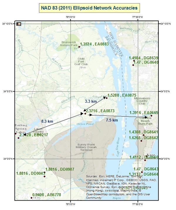
The user can retrieve NGS datasheets in text form or as a shape file using NGS’ Datasheet retrieval program. Identifying stations involved in a NGS Height Modernization Project is simple because the datasheet adds a note stating that a particular station is a Height Modernization Survey Station. The user can assume these stations were determined following NGS 58 guidelines. An example of a station involved in a height modernization project is station CARGO, DJ5933 (see the datasheet below). The NGS datasheet also lists the station’s network and local accuracies. On the datasheet, the network accuracy value is listed below the coordinates (for instance, 1.39 cm for station CARGO). Below the network accuracy value, the user can obtain the local accuracy values by clicking on the following link in the datasheet: “Click here for local accuracies and other accuracy information.” You can obtain the full NGS datasheet for CARGO.
The NGS Data Sheet for Height Modernization Station CARGO (DJ5933) PROGRAM = datasheet95, VERSION = 8.71 National Geodetic Survey, Retrieval Date = JULY 12, 2015 DJ5933*********************************************************************** DJ5933 HT_MOD – This is a Height Modernization Survey Station. DJ5933 DESIGNATION – CARGO DJ5933 PID – DJ5933DJ5933 STATE/COUNTY- NC/NEW HANOVERDJ5933 COUNTRY – US DJ5933 USGS QUAD – WILMINGTON (1979)DJ5933DJ5933 *CURRENT SURVEY CONTROL DJ5933 ______________________________________________________________________ DJ5933* NAD 83(2011) POSITION- 34 12 27.89075(N) 077 57 16.40009(W) ADJUSTED DJ5933* NAD 83(2011) ELLIP HT- -34.732 (meters) (06/27/12) ADJUSTED DJ5933* NAD 83(2011) EPOCH – 2010.00 DJ5933* NAVD 88 ORTHO HEIGHT – 2.05 (meters) 6.7 (feet) GPS OBS DJ5933 ______________________________________________________________________ DJ5933 NAVD 88 orthometric height was determined with geoid model GEOID03 DJ5933 GEOID HEIGHT – -36.78 (meters) GEOID03DJ5933 GEOID HEIGHT – -36.80 (meters) GEOID12BDJ5933 NAD 83(2011) X – 1,101,934.174 (meters) COMPDJ5933 NAD 83(2011) Y – -5,164,049.037 (meters) COMPDJ5933 NAD 83(2011) Z – 3,565,508.167 (meters) COMPDJ5933 LAPLACE CORR – -5.30 (seconds) DEFLEC12B
DJ5933
DJ5933 Network accuracy estimates per FGDC Geospatial Positioning Accuracy
DJ5933 Standards:
DJ5933 FGDC (95% conf, cm) Standard deviation (cm) CorrNE
DJ5933 Click here for local accuracies and other accuracy information.
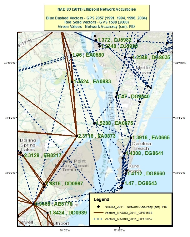
Local accuracies provided on the NGS datasheet can be used to determine if closely spaced stations were simultaneously observed during the same session. If two stations were simultaneously observed during the same session, they will have a local accuracy value listed in their table. Station TOWN CREEK (EA0883) is an example of a station that was simultaneously observed by BR 7 (EA0873) in one GNSS project and by LILIPUT (EA0875) in a different project. (Figure 1 depicts these stations and their NAD 83 (2011) network accuracy values.) Looking at the highlighted section of the tables below, station EA0883 is listed in the local accuracy tables for EA0873 and EA0875, so it was simultaneously observed during sessions with EA0873 and EA0875.
Saying that, we can also use the tables to show that EA0873 and EA0875 were not simultaneously observed during the same session. That is, EA0873 is not listed on EA0875 local accuracy table and EA0875 is not listed on EA0873 local accuracy table so they were not processed simultaneous in a session. Figure 2 depicts the two GNSS projects that include observations involving stations EA0873 and EA0875. The user can perform the same procedure to determine that stations EB0217 and EA0873, 8.3 km apart, were not simultaneously observed during the same session, and similarly EA0873 and EA0665, 7.5 km apart, were not simultaneously observed during the same project. Please note I am not suggesting that anything is wrong with these surveys; there may be good reasons why these stations were not simultaneously observed during the same project. I am only using it as an example in this column. Network and local accuracy values are good indicators of potentially “how good” a station is relative to its neighbor, but they should always be evaluated and investigated. My intent is to provide the user with tools for evaluating the quality of published NAD 83 (2011) ellipsoid heights. This is important because published coordinates are used to evaluate the adjustment results of new projects.
Local and Network Accuracy Data for NGS Datasheet – EA0873 Program lna_ret Version 2.7 Date April 6, 2015 National Geodetic Survey, Retrieval Date = JUNE 30, 2015 EA0873 ************************************************************ EA0873 ACCURACIES – Complete network and local accuracy information. EA0873 DESIGNATION – BR 7 EA0873 PID – EA0873 EA0873 EA0873 Horiz and Ellip are the horizontal and ellipsoid height accuracies EA0873 at the 95% confidence level per Federal Geographic Data Committee EA0873 Geospatial Positioning Accuracy Standards. SD_N, SD_E and SD_h are EA0873 the standard deviations (one sigma) of the coordinates (NETWORK) or EA0873 of the difference in the coordinates (LOCAL) in latitude, longitude EA0873 and ellipsoid height. CorrNE is the (unitless) correlation EA0873 coefficient between the latitude and longitude components of either EA0873 the coordinate (NETWORK) or coordinate difference (LOCAL). Dist is EA0873 the three-dimensional straight-line slope distance, in km, between EA0873 station EA0873 and the corresponding local station. Local stations EA0873 are stations processed simultaneously in a session regardless of EA0873 distance. EA0873EA0873 Accuracy and standard deviation values are given in cm.EA0873EA0873 Type/PID Horiz Ellip Dist(km) SD_N SD_E SD_h CorrNEEA0873 ——————————————————————-
Local and Network Accuracy Data for NGS Datasheets – EA0875 Program lna_ret Version 2.7 Date April 6, 2015National Geodetic Survey, Retrieval Date = JUNE 30, 2015 EA0875 ********************************************************** EA0875 ACCURACIES – Complete network and local accuracy information. EA0875 DESIGNATION – LILIPUT EA0875 PID – EA0875 EA0875 EA0875 Horiz and Ellip are the horizontal and ellipsoid height accuracies EA0875 at the 95% confidence level per Federal Geographic Data Committee EA0875 Geospatial Positioning Accuracy Standards. SD_N, SD_E and SD_h are EA0875 the standard deviations (one sigma) of the coordinates (NETWORK) or EA0875 of the difference in the coordinates (LOCAL) in latitude, longitude EA0875 and ellipsoid height. CorrNE is the (unitless) correlation EA0875 coefficient between the latitude and longitude components of either EA0875 the coordinate (NETWORK) or coordinate difference (LOCAL). Dist is EA0875 the three-dimensional straight-line slope distance, in km, between EA0875 station EA0875 and the corresponding local station. Local stations EA0875 are stations processed simultaneously in a session regardless ofEA0875 distance.EA0875EA0875 Accuracy and standard deviation values are given in cm.EA0875EA0875 Type/PID Horiz Ellip Dist(km) SD_N SD_E SD_h CorrNE
I haven’t discussed all procedures documented in NGS 58 here. There are other minor, but very important, procedures that the user must follow, such as use of precise ephemerides, taking a rubbing of the mark; the reader is referred to NOAA Technical Memorandum NOS NGS-58, “Guidelines for Establishing GPS-derived Ellipsoid Heights (Standards: 2 cm and 5 cm), Version 4.3,” for more details.
This column discussed procedures that need to be followed to detect, reduce and eliminate error sources to estimate accurate GNSS-derived ellipsoid heights. Analysis of the quality of project data should be based on repeatability of measurements, adjustment residuals and analysis of loop closures. Please be aware that repeatability and loop closures do not always disclose all problems, and that is why it is important to adhere to the procedures outlined in NGS’ publications.
It is important to understand geoid models when estimating GNSS-derived orthometric heights. The user should understand the differences between NGS’ scientific gravimetric geoid model and hybrid geoid models, and why it is important to use both types of geoid models in an analysis. As I mentioned in Part 1, the latest NGS hybrid geoid model, Geoid12B, is made consistent with the published NAVD 88 heights. This means you will be consistent with NAVD 88 when using GEOID12B to estimate GNSS-derived orthometric heights. However, this doesn’t guarantee that your GNSS-derived orthometric heights are accurate. NGS’ new Beta experimental geoid height model xGEOID14B is not distorted to fit the published NAVD 88 heights so it is useful for identifying valid NAVD 88 benchmarks. In my next column, I’ll address how to use these geoid models and published NAD 83 (2011) ellipsoid heights to evaluate potential issues with published NAVD 88 heights.
Figure 1. NAD 83 (2011) Ellipsoid Network Accuracies – units cm (Network accuracies were obtained from NGS datasheets).Figure 2. NAD 83 (2011) Network Design for Stations EA0873 and EA0875. [Note: GNSS Vectors for GNSS projects GPS 1588 and GPS 2057 were provided by NGS].
GPS World staff will cover the 2015 INTERGEO Trade Show, being held Sept. 15–17 in Stuttgart, Germany. The show opens with keynote speeches by Chris Cappelli (Esri) on location platforms and Georg Gartner (Vienna University of Technology) on the future of the map.
INSPIRE examines geo-issues from a European perspective, providing practical examples and focusing on further development of this European directive. Other central themes include geodata as a basis for construction management and land development, as well as issues relating to property markets and valuation.
A panel discussion on the second day tackles geospatial Information with a high-profile panel of speakers: Bengt Kjellson (UN-GGIM Europe), Ola Rollen (Hexagon), Steve Berglund (Trimble) and Chris Cappelli (Esri). Another key topic is geoinformation and mobility. DDGI and DVW will be addressing this together and discussing practical examples in two event strands.
A Big Data discussion focuses on the rapid development of data capture, processing and presentation as well as the direct integration of data into business processes.
As important as data may be in the digital world, it is also crucial to have the right visualization concepts in place. This will be demonstrated through presentations on German Cartographers’ Day, which will form part of INTERGEO.
Tap into our up-to-the-minute show coverage here at gpsworld.com and via Twitter (@GPSWorld). Below are the GPS World videos from INTERGEO 2014.
The GrAnt by JAVAD GNSS is a versatile high-performance antenna.
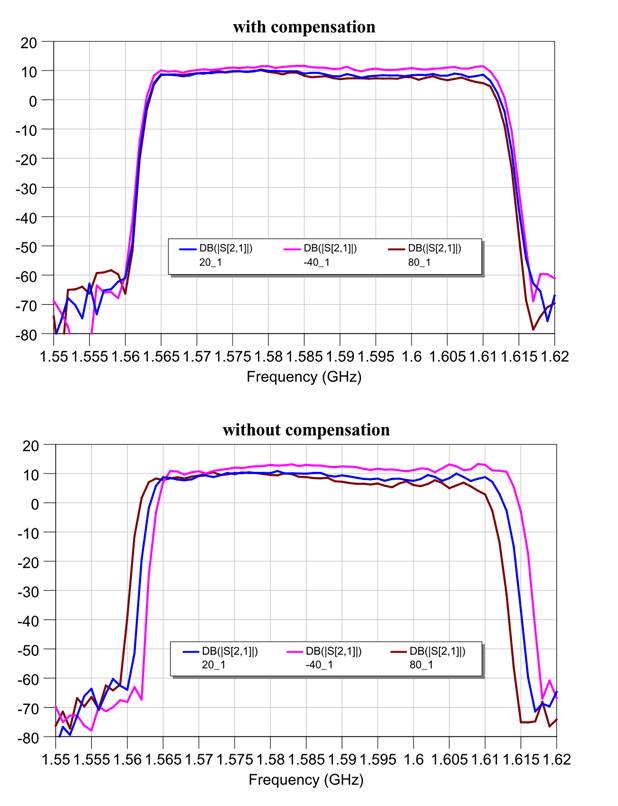
With J-shield — the JAVAD GNSS filter that protects GPS L1, Galileo L1 and GLONASS L1 bands — the GrAnt antenna can track GPS, GLONASS, Galileo, BeiDou, WAAS, EGNOS, MSAS, GAGAN and QZSS signals. J-shield brings in all the useful signals intact and rejects out-of-band signals with the slope of about 12 dB/MHz. Similarly, the filter protects GPS L2, GPS L5, GLONASS L2, GLONASS L3 and Galileo L5, and has slope of about 9 dB/MHz. The filters have been extensively tested with five different innovative tests that prove that the filters also improve the performance of GNSS receivers.
The GrAnt antenna can be mounted on flat surfaces with four screws or mounted on standard poles (5/8-11 or 1-14 inch thread). The antenna cable can be connected via the standard TNC (N-type optional) connector on its side or routed through the center of the antenna for ultimate protection in harsh environments.
An optional ground plane can be purchased to increase multipath mitigation.
The top-level model, the GrAnt-G5T, supports a wider band to accommodate additional signals, with frequencies of 1555-1610 MHz and 1164-1300 MHz. Full signal capability of the GrAnt-G5T is: