Wearable fitness trackers such as FitBit could help military patients recover quicker, according to Col. Deydre Teyhen, an official with from the Defense Health Headquarter’s Office of the Surgeon General. The trackers could help patients with musculoskeletal conditions gauge how much physical activity they can handle without exacerbating their injuries, Teyhen told an audience at a conference hosted by tech association, AFCEA and reported by NextGov.
Device-agnostic software is needed to allow soldiers to use the devices they already own, she said. “The question becomes, is it a one-size-fits-all solution?”
For instance, some patients begin to feel better before their soft tissue heals fully, and start walking around more, which could inhibit their recovery process, she explained. An effective system might send that patient a notification on their fitness tracker to say, “‘You’ve done great, at 1,000 to 2,000 steps a day,’ and it gives you a warning … ‘You might actually be doing too much and you might cause a setback.’ If you give them that warning in real time, then they can change their behaviors.”
Drifting tabular icebergs viewed from the Amundsen. (Photo courtesy of Greg McCullough, University of Manitoba)
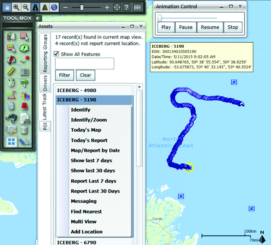
A Canadian expedition team used GeoDecisions’ GeoILS platform to help track icebergs during a voyage to better understand how icebergs drift. An intelligent location server using the Esri ArcGIS platform, GeoILS enables users to monitor and locate assets and facilitate quick and coordinated responses.
GeoDecisions, an information technology company specializing in geospatial solutions, partnered with Solara Remote Data Delivery Incorporated, Canada’s Carleton University and Esri during the project.
The FT2000IB Solara tracker. (Photo by Tom Tessier)
Led by University of Manitoba Scientist David Barber, the crew of Canadian Coast Guard icebreaker Amundsen sailed off the coast of Newfoundland and Labrador to research ice hazard mitigation, the effects of climate change, and polar region technology requirements. GeoILS location intelligence helped crew members visualize, analyze, and leverage project-pertinent data.
“During the expedition, researchers and scientists used GeoILS to assess drifting through sensor monitors attached to the icebergs,” said Brian Smith, vice president of commercial solutions with GeoDecisions. “In addition to reporting and notifications, GeoILS provided the project team with maps that were tailored by selecting desired iceberg information and the geographic area of interest based on user-defined criteria.”
GeoDecisions’ data portal was used with Iridium Solara tracking devices during the iceberg research project. Two icebergs were outfitted with FT2000IB Solara trackers, explained Derek Mueller, assistant professor and physical geography program supervisor with Carleton University.
THE GROUND control point and beacon. (Photo by Derek Mueller)
For each iceberg, two beacons were attached for redundancy and to determine the iceberg’s rotation. Holes were drilled and stakes inserted, then GeoDecisions Platform Tracks Icebergs the trackers attached to the stakes.
The trackers were also used as ground control points for photogrammetry, specifically the structure from motion ranging imaging technique.
“GeoILS and the satellite tracking beacons worked very well during this project,” Mueller said. “Thanks to our partners’ efforts, we now have a great new suite of tools for examining our data.”
“We are excited to provide tools to scientists who are gaining critical insights into the behavior of icebergs and global climate change,” said Tom Tessier, president of Solara Remote Data Delivery Incorporated.
The last tracker stopped transmitting on June 13. “The others ended earlier, likely because the iceberg rolled or broke up,” Mueller said.
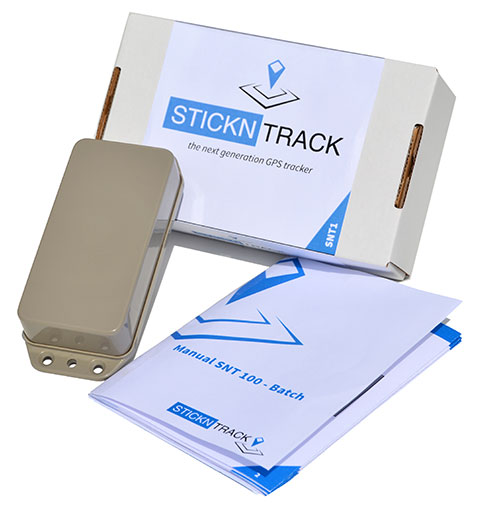
StickNTrack — an award-winning low-power tracker from Sensolus — is now active in eight European countries.
StickNTrack guards and tracks position, journeys, motion and status of any non-powered asset without the hassle of charging batteries, managing SIM cards or an intrusive installation, Sensolus said.
StickNTrack’s web-based service platform is tailored for low-power asset tracking communicating over the French-based Sigfox. Because Sigfox is an ultra low-power communication network, it significantly reduces StickNTrack’s power needs so that it consumes up to 40 times less power and lowers life-cycle costs by 50 percent compared to existing compact GPRS/GPS products, Sensolus said.
The tracker’s power can last up to five years. In the third quarter, an upgraded version will be released with extended battery lifetime up to nine years, according to Kristoff Van Rattinghe, who developed StickNTrack along with Laurence Claeys, Johan Criel and Koen Van Vlaenderen.
Users can access the StickNTrack web portal with any smartphone running Android OS or iOS. The full feature set can be accessed on a tablet or laptop. Features include interactive timelines, intuitive geofencing, email alerting and optimized energy savings.
The ruggedized, waterproof StickNTrack is 120 x 50 x 25 millimeters and weighs 255 grams. It can track assets on the water, such as yachts or buoys, providing automated logbooks, alerting users when assets enter or exit specific zones (such as harbors), and providing real-time journey information for those at home.
StickNTrack’s developers took third place in the 2014 European Satellite Navigation Competition, after taking first in the Flanders regional competition. It also won the European Space Agency’s Innovation Award.
Dubbed a “distruptive innovation” by the European Satellite Navigation Competition (ESNC), StickNTrack “opens up an abundance of new business opportunities in tracking trailers, containers, machinery, tools, bikes and more. Future accuracy and availability improvements based on GNSS will trigger additional advancements, such as by automating supply chains for packages and their delivery. Ultimately, stickNtrack is a next-generation location tracker that significantly lowers the barriers to embedding even more GNSS technology into our daily lives.”
“Every day new types of non-powered assets are being connected to our service platform,” Van Rattinghe said. In the coming years, Sigfox aims to provide global coverage.
TomTom’s map and traffic information have been chosen by the University of Minnesota’s Accessibility Observatory as part of a new national accessibility data set.
TomTom will provide map and historical speed data to help analyze accessibility to jobs for driving and transit for metropolitan areas across the United States. For transit data, the Observatory is relying on open, public sources using a method developed at the University with support from the Center for Transportation Studies.
Study partners will be able to use this data for policy development, local transportation system evaluation, performance management, planning and research efforts. Each partner will have direct digital access to the accessibility datasets for the jurisdictions of all partners and will receive detailed reports of local accessibility trends and patterns. The Minnesota Department of Transportation is the lead agency and coordinator for the national pooled-fund study. Other participating agencies are the Federal Highway Administration (FHWA) and the DOTs of California, Florida, Iowa, North Carolina, Virginia and Wisconsin.
“Today’s transportation user wants more than mobility — they want accessibility and they want MnDOT to invest in the appropriate solution, at the right place, at the right time, and at the appropriate cost,” said Tim Henkel, division director of modal planning and program management at MnDOT. “The Accessibility Observatory offers solutions to these decision-making challenges.”
The Transportation Pooled Fund Program, part of the National Cooperative Highway Research Program, allows state DOTs, FHWA program offices, and other organizations to combine resources and achieve common research goals. Additional partners are welcome to join the study.
“We’re excited that the UMN Accessibility Observatory has selected TomTom to help provide geospatial and transportation information for this project,” said Ralf-Peter Schäfer, head of traffic at TomTom. “We are confident that the TomTom map and traffic content will contribute to a better understanding of job accessibility nationwide.”
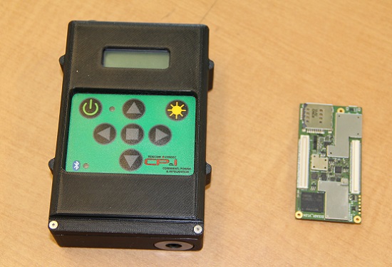
The current WINS form factor (left) sits beside a prototype for the future incarnation.
The Evolution of the Warfighter Integrated Navigation System
A new device is being developed to enable foot soldiers to find their exact location in GPS-denied situations. If satellite signals are blocked by heavy jungle canopy, or because of enemy interference, soldiers — and Headquarters — will still know where they are with the Warfighter Integrated Navigation System (WINS).
WINS will be a compact, wearable navigation device capable of operating either as a standalone system or networked to distribute position location information to other soldier platforms. WINS will extend positioning capability for soldiers in environments where GPS is not available, reducing the effect of GPS interference and enabling integrity monitoring for trusted position reporting.
The technology behind WINS is being developed at the U.S. Army’s Communications Electronics Research Development and Engineering Center (CERDEC) labs. “WINS will be not just one technology; it’s a soldier-worn multi-sensor source incorporating information from GPS, inertials, vision-aided navigation, RF ranging, etc.,” explained John DelColliano, chief for CERDEC’s PNT Branch, which falls under CERDEC’s Command, Power and Integration Directorate (CP&I).
“All these will tie in to making a more robust navigation system, so if you’re in a situation where GPS fails, you can have other things to back you up.” For instance, inertial sensors will calculate an offset from the last-known GPS location using footsteps taken, speed, acceleration and time.
“The bottom line is that the soldier, without having to do any extra work on his own, will have a navigation system on his person that will provide him with a solution that he can count on when he needs it,” DelColliano said.
WINS is expected to help eliminate dependence on vulnerable commercial receivers. It will improve positioning in GPS-degraded environments, enduring some jamming and providing positioning indoors and in urban areas. It will enable soldier-based cooperative engagements and provide trusted dismounted soldier position through integration with Selective Availability Anti-Spoofing Module (SAASM) GPS receivers and redundant navigation sensors.
“CP&I’s PNT branch has worked on these individual technologies for many years, but we’ve always had the vision of an integrated solution,” DelColliano said. “That’s where we are today. It makes the most sense for what the soldier is going to need in the battlefield.” With a WINS-equipped solder, DelColliano said, “We’ll be able to know where he is and at what time, and we’ll be able to track if something happened to him. This capability will also enable our forces to be more mobile and maneuverable. It allows the commander and HQ to see where each squad is.”
As part of a technology demonstration program at Fort Dix, N.J., WINS is being developed under an incremental build process as researchers consider what functionality should be incorporated. The engineering specifications for WINS are expected to be transferred to Program Executive Office, Intelligence and Electronic Warfare & Sensors by 2017, and from there eventually be made available to soldiers.
Future WINS capabilities
The final version of the WINS will have the following capabilities:
Military GPS for a protected signal and anti-jam capability on the soldier.
Inertial measurement unit for soldiers to track their location.
RF ranging using a radio or radio-like device to communicate between soldier-worn nodes and determine the range between soldiers, computing positions through triangulation relative to GPS.
Vision-aided navigation using the same kind of camera as in a cell phone, which is ideal for SWaP-C (size, weight and power compliance), to help navigate by tracking the soldier’s motion through an environment.
TomTom has added navigable maps for 13 new countries. TomTom’s global map database now covers more than 45.6 million kilometers and 4.3 billion people worldwide, and features full navigable coverage for 134 countries.
“The addition of nearly 3 million kilometers of roads in one year demonstrates TomTom’s commitment to geo-expansion,” said Charles Cautley, managing director of TomTom Maps. “We rely on intelligent mapmaking and our transactional mapmaking engine to continuously deliver map updates around the globe, increasing coverage and improving map features for all business customers.”
Global map enhancements include:
The launch of navigable, turn-by-turn maps for Macedonia, Bosnia & Herzegovina, Peru, Guatemala, Nicarágua, Panamá, Costa Rica, Honduras, El Salvador, Iraq, Ghana, Rwanda and Burundi.
Introduction of Address Points to enable better geocoding and navigation in Austria, Luxemburg, Turkey and South Africa; significant growth in Address Point coverage for South East Asia reaching 3.6 million.
Significant Points of Interest growth in Mexico, bringing count to more than 3 million.
Launch of 3D Map for Singapore and the debut of visualization products for the Middle East, with an Advanced City Model of Riyadh and 2D City Maps for 15 cities.
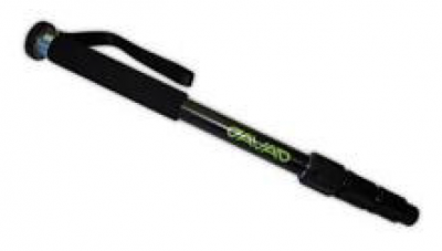
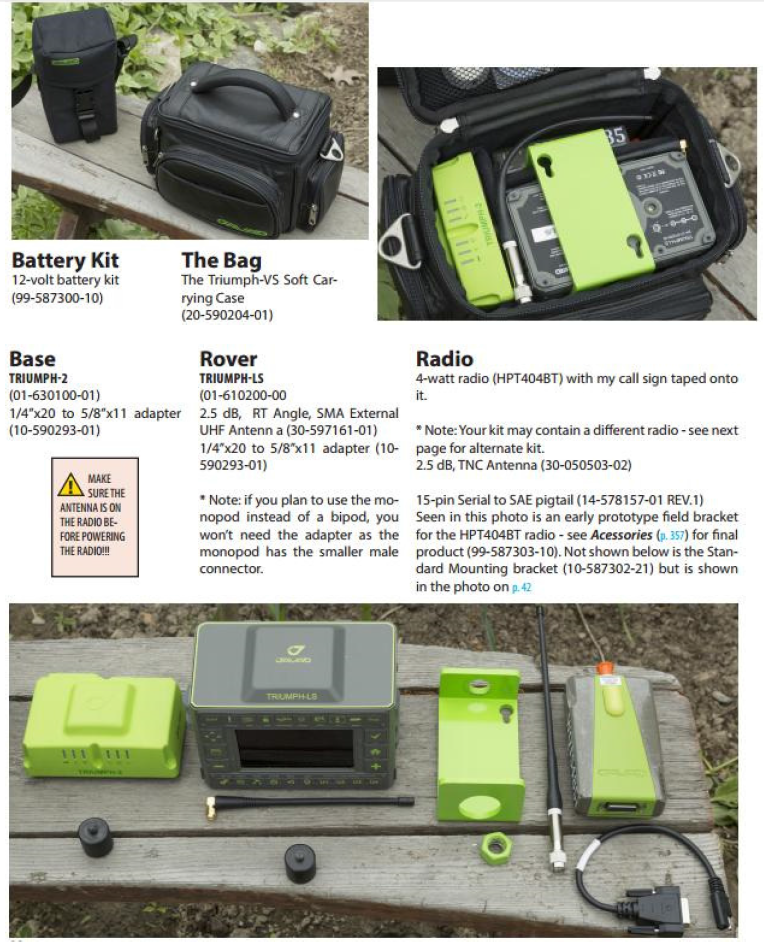
I follow the surveyor connect message board and have seen some general discussion of the form factor of the Javad Triumph LS. I wanted to go into a little more detail on the form factor and portability of a couple of the receivers in the Javad GNSS lineup.
Most surveyors that have been using RTK GPS equipment have been trained to keep their rod height at 2 meters to reduce error in rod height adjustment and to be able to get above general multipath hardships. This is not required with the Javad Triumph LS. The advanced multipath reduction of the Triumph LS gives the surveyor the flexibility to have the receiver anywhere from just over 1-foot high to as high as your pole may reach. The Triumph LS comes standard with a collapsible monopod pictured here.
With the Triumph LS being an advanced GNSS receiver and data-collection system all in one, you may ask. “But what if I have to raise the pole above an obstruction to get a shot?” The Triumph LS is equipped with an audible tone and time-delayed shot setting, an internal level, an internal compass and a flashing LED light on the bottom of the receiver that all work together to allow the surveyor to collect points on objects with the receiver high above the surveyor’s head (out of sight). The LS is also equipped with a proximity sensor that will allow you to take a shot even if you cannot reach the receiver’s screen. For instance, you are out in a swamp and you can reach out and get the pole generally level (with internal tilt compensation turned on), but you cannot reach up and start collecting the shot. Wave your hand or a lath in front of the LS, and it will start recording your shot. So no matter your height or the height of the obstructions, you can still get the shot that you need.
The form factor of the LS, while it is much different than what we are used to using, works extremely well. The LS rover paired with a Triumph 2 base is one of the most portable systems on the market as well. The Triumph LS, Triumph 2, 4-watt external UHF radio and UHF power cable all fit into a small camera bag.
This is the system that I personally use on a regular basis. I find that the ability to collapse the monopod allows me to easily use both hands while riding on a four-wheeler along with the ability to easily pack up the system on the four-wheeler to set up the base in more remote locations. With nearly two years of using this system, the form factor has not once been an issue. Quite the contrary — the form factor makes it much easier to navigate dense brush and have more control over the equipment.
For more information on Javad’s J-Field software, the Triumph LS or other Javad GNSS solutions, please feel free to visit www.javad.com, email [email protected] or call 1-888-550-5301 or 1-408-770-1770.
A Mountaineering Survey Team Determines K2’s Actual Height
Surveying the world’s highest peaks is a daunting task. One international survey team set out to measure the Himalaya’s K2 peak, the second highest in the world after Mount Everest.
In 2004, 50 years after an Italian team led by Ardito Desio first summited, a team tried to measure K2 with GNSS surveying equipment, but the attempt to bring the GNSS receiver to the top failed when a climber fell.
For the most recent attempt, a Pakasti-Italian team took along a rugged industrial survey system 60 years after the first summiting, in June–August 2014.
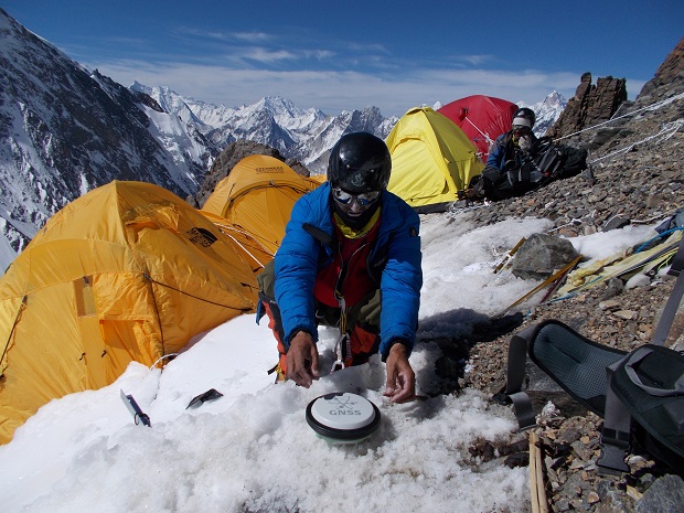
The team performed measurements at five different climbing campsites and on the K2 summit, using GNSS technology to collect the most accurate measurements ever made of K2.
The measurements were accomplished by Pakistan’s Rehmat Ullah Baigh and Italy’s Michele Cucchi, who set up the receiver at each stop and allowed it to remain for approximately 20 minutes to collect the latitude, longitude and altitude of each point from the available satellites.
Setting up camp also meant setting up a GNSS receiver to gather data.
One reference receiver was permanently positioned by team technical leader Maurizio Gallo close to the K2 Base Camp at the Gilkey Puchot Memorial, which is dedicated to climbers who died on K2. A second reference receiver was placed in Skardu, a final stop before heading up the mountains. At Skardu, computer expert Fida Hassain from Central Karakorum National Park helped install and process the transmitted data along with researcher Aamir Asghar and Giorgio Poretti, professor at the University of Trieste. The coordinated network of two permanent GNSS stations allowed data from the summit to be processed with excellent precision and is still in operation today.
After the climb, the data was downloaded from the receivers and analyzed. The GNSS survey results lowered K2’s height from its previous altitude of 8,610.34 meters (28,248.03 feet) to 8,609.02 meters (28,244.75 feet) — 1.5 meters (3.3 feet) shorter than previously believed.
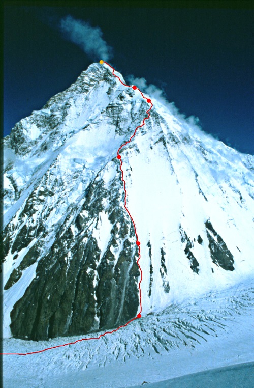
The route to K2’s summit.
Yet the biggest surprise was at K2’s Camp Four on the Abruzzi Spur, where expeditions on this route begin their final ascent to the summit. Previous measurements stated that the route began at 7,900 meters (25,920 feet). The new data collected proves that the route starts at 7,747.029 meters (25,416.667 feet), making the climb 150 meters (492 feet) longer than previously recorded. This is a challenging difference for K2 climbers, who at this point are struggling for weeks with the weakening effects of altitude sickness
and the stress of staying focused.
The team also plans to climb Mount Everest, where a reference station is located very close to the EVK2CNR’s Pyramid International Laboratory on the Nepali side of Mount Everest.
Manufacturer
The survey team used the Leica Viva GS14 GNSS receiver and two GX1230+ reference receivers and antennae provided by LeicaGeosystems. Leica Geosystems used the opportunity to test its equipment’s portability, resistance to very low temperatures and rugged use on rough tracks.
Adapted from an article by Katherine Lehmuller and Marco Mozzon in the Reporter (#72), the Leica Geosystems customer magazine, and other sources.
A team of four climbers has returned from the highest point in North America, Mount McKinley in Alaska, with new GPS survey data to determine a more precise height of the mountain’s summit. The data collected will update the commonly accepted elevation of McKinley’s peak, 20,320 feet. The last survey was completed in 1953.
The USGS, along with NOAA’s National Geodetic Survey (NGS), and the University of Alaska Fairbanks (UAF), are the primary partners supporting the survey. The survey party included three mountaineers from CompassData, a subcontractor for Dewberry and a scientist from UAF’s Geophysical Institute.
Using modern GPS survey equipment and techniques, the partners will be able to report the summit elevation with a much higher level of accuracy and confidence than has been possible in the past. It is anticipated the newly surveyed elevation will be announced in late August.
After months of negotiation, Nokia will sell its HERE Maps division to a consortium of German automakers — BMW, Daimler and Volkswagen — for $2.71 billion, according to the TU Automotive website.
Under the agreement, HERE Maps would turn into an open platform that all car manufacturers can use for navigation and mapping inside vehicles, giving automakers independence from companies such as Google for maps and navigation at a time when the technology moves toward the connected and self-driving car, which rely on navigation technology.
The three German car makers plan to offer the platform to Fiat Chrysler, Renault, Peugeot, Ford, Toyota and General Motors, allowing them to use the mapping service for free without licensing issues.
Nokia is selling the entire unit of HERE, meaning the car consortium will likely continue hiring developers to work on the platform. Companies like Chinese search giant Baidu and Facebook use HERE Maps to power its own mapping services. It remains to be seen how the new deal will affect those services.
“Only with high-precision maps will automated driving on freeways be possible from 2020,” said Bosch board member Dirk Hoheisel. TomTom says it plans to have new high-precision maps for automated driving for all freeways and freeway-like roads in Germany by the end of 2015.
AGCO and Trimble are partnering to deliver wireless connectivity between AGCO’s VarioDoc and AgCommand systems and the Trimble Connected Farm solution. The functionality is expected to be available to customers in North America in September and in Europe, Africa and the Middle East in the fourth quarter of 2015. AGCO is a worldwide manufacturer and distributor of agricultural equipment and infrastructure.
The collaboration allows customers to access their AGCO machine data via AGCO’s telemetry product AgCommand, as well as their agronomic data through AGCO’s VarioDoc task file management platform, from within the Trimble Connected Farm dashboard. This deeper integration of AGCO and Trimble technologies delivers a more streamlined approach to total farm management, simplifying the grower’s ability to access and act on live machine and task data within a single, Web browser-based user interface, the companies said in a statement.
“The inclusion of AGCO’s AgCommand information into Connected Farm aligns well with Trimble’s continued focus on providing a complete solution for growers to manage a mixed fleet of vehicles and implements,” said Joe Denniston, vice president of Trimble’s Agriculture Division. “AGCO customers now have access to one central location in Connected Farm for monitoring their farm operations including fleet data, rainfall and weather information, commodity quotes, and irrigation monitoring to enable improved decision making from the office to the field.”
“This collaboration gives our customers easier access to their operational data for enhanced productivity, mobility and decision making,” said Eric Hansotia, senior vice president, Global Harvesting, Crop Care, Advanced Technology Solutions and Dealer Tech Support at AGCO. “Strategic development with platforms like Connected Farm gives growers a single location from which to monitor their entire operation.”
The development expands on the February 2014 announcement of the connection between Trimble’s Farm Works Software and VarioDoc. This new integration will give Trimble customers the option to sync their task data sent via VarioDoc in either Farm Works or Connected Farm.
The integration between Trimble’s Connected Farm and AGCO’s AgCommand will be the first to utilize AGCO machine data via the AgCommand API (Application Programming Interface). The API will open globally in the fourth quarter of 2015 to developers and service providers who wish to incorporate machine data into custom applications and tools for growers. This offers more points of access to end users, allowing AgCommand data to be integrated into the grower’s farm management platform of choice.
Trimble joins AGCO’s growing list of partners that are part of AGCO’s Fuse Technologies open approach to precision agriculture and precision machine management.
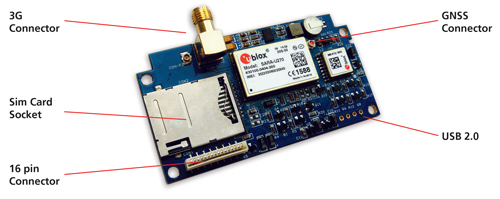
Reyax Technology, a telematics tracking systems provider for the automotive industry, has developed an industrial high-integration 3G GNSS tracking platform, the Reyax RY277AI, which is fully based on technology from u-blox.
“Our vehicle tracking platforms are dependent on highly accurate position data to deliver the performance crucial to meet the demands of our customers. u-blox’s highly reliable products as well as a flawless technical support were convincing,” said Ritchie Chang, general manager of Reyax Technology. “u blox’s MAX M8C positioning module and SARA U270 cellular module were the right choice for this new platform,” he added.
RY277AI is designed for 3G telematics applications, in particular vehicle tracking, fleet management and insurance box. With both MAX-M8C and SARA U270 modules embedded, it also benefits from two of u blox’s GNSS and wireless technology services. With AssistNow, Assisted GNSS (A-GNSS) accelerates the calculation of a position by delivering satellite data to the GNSS receiver via wireless networks or the Internet, also ensuring faster TTFF (time to first fix).
CellLocate, another of u-blox’s trademarked technologies, matches cellular positioning data with previously successful GNSS fixes in shielded environments such as indoors. This is especially useful in case of jammed GNSS signals and in M2M applications. Additionally, u-blox’s nested design enables hosting of next-generation wireless and positioning modules on the same PCB.
“We are excited about this co-operation with Reyax Technology, the recognized leader in telematics tracking systems. Reyax-based solutions make full use of u-blox’s advanced positioning and cellular technologies to enhance vehicle tracking. This solution is an answer to the growing encouragements by the Taiwanese government to promote IoT/M2M applications and whose vision we share.” explained Ming Chiang, country manager of u-blox Taiwan.
RY277AI comes in an LGA package, with a dimension of 70mm x 30mm x 7mm, and an operating temperature of -40~+85° C.