I didn’t plan it this way, but my coverage of GPS 24+3 turned out to be a three-part series, with this column being part three. One reason it turned into a three-part series is because I’m learning more about it along the way, but its mostly because details weren’t released all at once.
The good news is that I (along with help from others….thank you) was able to generate an almanac that simulates 24+3 reasonably well. The idea behind doing this is that I could compare the satellite visibility plots in satellite visibility software using both the original almanac (I chose January 1, 2010) and a GPS 24+3 modified version of the same almanac. For those plots, I could present to you what you can realistically expect the improvement to be with the 24+3 satellite configuration.
A quick note before diving into the 24+3 configuration. At the end of this column is a brief discussion about solar activity and GNSS/GPS. Last week, there was a solar event and some users have voiced concerns about that. I’ve addressed those in a section at the end of this article.
24+3
You can view my first two columns relating to the 24+3 configuration by following these links:
I’d like to update you on some bits of information that I’ve learned about 24+3 since my last column. I asked the HQ Air Force Space Command some questions about 24+3 and they kindly responded.
EG: Will the satellites (SVN24, SVN26) remain healthy during their repositioning journey?
HQ AFSC: Yes. The satellites will be set unhealthy for the initial Delta-V, but will return to healthy status approximately 24 hours after initiation of the Delta-V. Initial Delta-V for SVN24 was accomplished on 13 Jan 10 and returned healthy on 14 Jan 10. SVN 24 will take up to a year to reach its final destination. Initial Delta-V for SVN 49 was accomplished on 21 Jan 10 and will arrive at its expanded position in Jun 10. Initial Delta-V for SVN26 will begin early Feb 10.
EG: Why the two-year timeframe to realize the benefits when all repositioning will be complete in 12 months?
HQ AFSC: The two-year timeframe is a conservative estimate which takes into account potential operational necessities which could extend the time required for completion. We must take a disciplined approach to cover possible failures and ensure continuity of coverage during the transition.
We will be adding GPS IIF vehicles to the constellation and older vehicles may fail during the transition timeframe. As vehicles are added and removed, the current plan is subject to change in order to provide the best service to all civil and military users. Some of these decisions could require additional time to complete the expanded constellation. However, benefits will likely be realized well in advance of 24 months.
EG: What is the reasoning behind using SVN49 as a key component of the 24+3 configuration since it won’t benefit a significant portion of the civilian user community, namely aviation and marine navigation as well as other SBAS (WAAS) and DGPS users? In my understanding, the FAA’s and the Coast Guard’s user bases are primarily single-frequency pseudo-range, users who won’t be able to use SVN49.
HQ AFSC: SVN49 was selected because it is a brand-new satellite with four good clocks. Although issues with SVN49’s navigation signals may make it unusable for all civil use, it could still put out a valid set of signals for military use. The Air Force team is continuing to work “open book” with civil and industry GPS experts to determine the possible outcome of SVN49. Although SVN49 is not currently healthy, GPSW and 50th SW are actively working a mitigation that may allow setting the vehicle healthy in the future. As a mitigation in case we are unable to set SVN49 healthy, SVN30 will be rephased to the same slot following a successful launch and on-orbit checkout of IIF-1. We expect to have either SVN30 or SVN49 healthy and broadcasting from the expanded slot within a 24-month timeframe. At this time, no decisions have been made and no options have been ruled out regarding SVN49.
Satellite Visibility Plots
As promised, I’ve (with help) been working on creating an almanac that simulates the 24+3 constellation. My goal was to be able to show you what the benefit to you will be with the new GPS 24+3 satellite configuration.
The method I used was to modify an almanac from January 1, 2010. The reason I chose that day is because it was before the satellite repositioning began. The first satellite began its repositioning journey on January 13, 2010.
Within the almanac, I adjusted the position of three of the satellites in the almanac to reflect the new orbit locations they are going to assume.
SVN 24 is moving from slot D5 to slot D2F
SVN 26 is moving from slot F5 to slot F2F
SVN 49 is moving from slot B5 to slot B1F
Following is a graphic I’ve published before that illustrates the satellite repositioning:
Using the original January 1, 2010, almanac to plot a satellite visibility chart and then using the 24+3 modified almanac to plot another chart for the same location, I was able to generate the following comparisons between the current GPS satellite configuration and the 24+3 satellite configuration. Please note the following:
A 15-degree elevation cutoff was used to account for obstructions (terrain, buildings, trees).
The modified almanac does not take into account the other three satellites that are being slightly repositioned (SVN46, SVN55, SVN56) so the modified almanac represents a worst-case scenario.
The original almanac is the first plot. The modified 24+3 plot is directly below it.
Portland, OR USA (N45 41, W122 11) Original Almanac:
Portland, OR USA (N45 41, W122 11) 24+3 Almanac:
Miami, FL USA (N25 46, W80 11) Original Almanac:
Miami, FL USA (N25 46, W80 11) 24+3 Almanac:
Tokyo, Japan (N35 42, E138 30) Original Almanac:
Tokyo, Japan (N35 42, E138 30) 24+3 Almanac:
London, England (N51 30, W000 07) Original Almanac:
New Dehli, India (N28 54, E77 13) Original Almanac:
New Dehli, India (N28 54, E77 13) 24+3 Almanac:
Rio De Janeiro, Brazil (S22 27, W42 43) Original Almanac:
Rio De Janeiro, Brazil (S22 27, W42 43) 24+3 Almanac:
Bangkok, Thailand (N13 49, E100 28) Original Almanac:
Bangkok, Thailand (N13 49, E100 28) 24+3 Almanac:
Perth, Australia (S31 49, E116 10) Original Almanac:
Perth, Australia (S31 49, E116 10) 24+3 Almanac:
A Quick Note about Solar Activityand GNSS/GPS
I’ve read media reports and I’ve been asked about a solar event that occurred last week (Thursday, February 12) and what possible effect it had on GPS operations.
I consulted with Joe Kunches of the NOAA Space Weather Prediction Center to understand how significant of an event it was.
“There was some activity but I would not think it would have an impact on GPS,” stated Kunches.
I asked him at what point would GPS operations be affected.
“As for flares (Radio Blackouts on the NOAA Scales), I’d say 10 to 20 times stronger than last week (R3 to R4 and above) would be sufficient to affect GPS on the dayside, but not for long,” said Kunches.
So, although there were media reports about the solar event last Thursday, if you had trouble with your GPS it wasn’t due to solar activity.
However, solar activity is a serious issue for GPS users, especially those using high-performance L1 receivers (sub-meter). You can be sure that I’ll will be covering this subject in-depth as we move further into the current solar cycle.
If you haven’t seen the announcement regarding my Webinar this Thursday (February18, 10 a.m. Pacific Time, 1800 hrs GMT), you might be interested. The title is “GPS for GIS – 101.” It’s a beginner’s (and refresher’s) guide to using GPS for GIS data collection. I’ve invited Craig Greenwald as Guest Commentator.
With apologies to James Bond, Ian Fleming, and, well, just about everybody else. Here is a grab from my mail bag. The message was subject-lined: GPS Spy Applications.
“I recently suspected my wife of cheating, having been involved with gps as a land surveyor since 1995, I used and application called mobile-spy.
“In order to install the application onto an iPhone you have to “jailbreak” the phone. Once its installed it will forward all text, url’s, and a gps location every 30 minutes if it has satellite availability. To make a long story short, I caught my wife in a pretty precarious spot, or spots. It’s my opinion that she was sneaking out and meeting someone at various spots on our normal routes, little hidden offroad trails if you know what I mean. Well I tested and retested the phones gps and the data from the mobile-spy website where I purchased the software, which is actually sold under the name “retina-x” and they make there money by giving you access to these logs through mobile-spy.com.
“However, my wife contests that all this data is wrong, of course, and she’s never been anywhere near these places. On the other hand, I have a ton of evidence saying she WAS at these locations. She says she’s read an article on AT&T that shows evidence that the gps in the iPhone is faulty and gives out bogus locations. As I said, I tested this a couple of times and it seemed to work perfectly.
“In good faith we’ve agreed to let me take the iPhone and perform more in depth tracking over a span of a few weeks. I am not really a writer but I’ll definitely keep detailed logs of my observations. Have you guys already had this particular issue come up before? If so, I’d love to know anything you can tell me because the way it stands I am getting a divorce unless this application can be proven wrong! My email is [email protected]
Cell phone is XXX.XXX-XXXX, I don’t check voicemails, so if I don’t answer just send me a text with your name and number. I look forward to hearing from you soon.”
Sleep was what I wanted, you know what I got. Wide awake, staying up late, wishing I was not.
Call it Madden withdrawal. It’s bad enough that I just endured Super Bowl XLIV without the smooth and engaging color commentary of the iconic John Madden, the legendary Hall of Fame, Super Bowl XI winning coach and virtual football entrepreneur. This year I patently missed John’s pithy commentary and the distinctive timbre of his voice. Coach Madden’s broadcast career has continued for more than thirty years and his instantly recognizable voice always invokes the desire to watch a football game. I would watch any game he color-commentated even if I did not particularly care about the competitors. It just wasn’t the same Super Bowl this year without John Madden, but somehow I soldiered on.
Col. David Madden.
The other Madden I’m going to miss and so will many of you, even if you don’t know it yet, is Colonel David Madden (USAF). Dave serves as the GPS Wing Commander at SMC (Space & Missile Systems Center) in Los Angeles, California, and will be stepping down as early as May, and hanging up his U.S. Air Force uniform at the same time. Dave has been the voice of GPS for many of us since he became the GPS Vice Wing Commander in July 2006. He became the commander in June of 2007, but he made his presence known the minute he landed at SMC. Dave has been a hard charger for the last 30 years and has numerous accomplishments of which he can be justly proud, but Dave hit his stride when he arrived at the GPS Wing. He was the right leader in the right place at the right time. Dave was immediately credible in the GPS world because of his previous forays in the classified and unclassified space arena.
Colonel Madden, the consummate military professional, who once described himself as a dangerous entity because he thought outside the box known as the military establishment, displays the immediately recognizable confidence of a leader who knows his job and emphatically embraces his mission; yet he is not overly arrogant and is always willing to listen. Sometimes he even deigns to speak honestly and openly to journalists. Dave has been the undisputed leader of the GPS Wing at a time when leadership was sorely needed. He used his engineering, systems management, and leadership expertise to create a cohesive team at the GPS Wing that simply and consistently gets the job done. His GPS accomplishments are many, but his greatest may be that he put the GPS back on the path as the PNT (Position, Navigation and Timing) and GNSS (Global Navigation Satellite System) gold standard for the world. He knows how to listen and take advice, and he knows when to stop debating, discussing, and dare I say arguing, and make the hard decisions. He and his finely honed force at SMC work tirelessly and intelligently to grow the GPS constellation in size and accuracy, but most importantly he is relentless in his support of the warfighter during a time of war.
Colonel Madden is a true patriot and fortunately he is not going far; rumor has it he will soon be an SES (Senior Executive Service) government civilian in yet another important space sector at SMC. Dave will be sorely missed by those of us that have had the honor to work closely with him in the GPS global arena for the past four years. Best of luck, Dave.
Col. Bernard J. Gruber.
Of course we also give a hearty welcome to Colonel Bernard J. (Bernie) Gruber, the new GPS Wing Commander or SPO (Special Program Office) director, as there is apparently a name and responsibility change or regression under way at SMC for various Wing-level organizations. Colonel Gruber served previously at SMC in the former GPS SPO in the user equipment office, the foreign military sales office, and as the program manager for Advanced Military Devices. So while he is not new to the space business or to GPS, he does have some large shoes to fill and we wish him well. If Bernie is half as smart as we know he is, he will be having some long and candid conversations with Mr. Madden, and I don’t mean the football legend.
Updates
There is so much happening in the PNT world that I could write a book. I promise not to do that, but an in-depth column is appropriate and you will see that in the near future. For now, allow me to quickly update the status of several ongoing programs and recent events.
24+3
We scooped the world at GPS World on 24+3 and fortunately everything is on schedule and working as planned. Two of the satellites are currently in their long transfer orbits and SVN 26 should start to move this week. Both SVN 24 and SVN 26 are Block-IIA satellites and are consequently a bit long in the tooth; 11 of the original 19 IIAs launched between 1990-1997 remain on orbit. These geriatric satellites are presently operating on different types of atomic clocks but their overall timing accuracy is not diminished, still averaging 1x10E-14. SVN 24 is currently utilizing a Caesium (also written Cesium) atomic clock and SVN 26 is utilizing a Rubidium atomic clock. This is a good mix for the plus three satellites as Caesium is nominally better over the long term for time stability and Rubidium is stable over a shorter period of time without periodic updates.
See Eric Gakstatter’s recent articles in GPS World for more technical information on the new locations for the three GPS satellites that are, or about to be, on the move.
GPS IIF. Photo: IIF
IIF
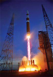
I received a plethora of mail recently either asking or raging about the status of the Boeing IIF, next generation of GPS satellites. I won’t even attempt to recount all the schedules and budgets this critical program has busted. The important point is, according to the latest schedule, sometime this month, hopefully in the next 10 days, IIF-SV1 will arrive at Cape Canaveral in Florida where it will subsequently be integrated with the Delta IV EELV or Evolved Expendable Launch Vehicle. This will be the first EELV to launch a GPS satellite; therefore, the integration and testing times, both on the ground and on orbit, are expected to be considerably more extensive than normal. Plus there are some unique features of the Delta IV that bear watching. The first stage of a Delta IV consists of one or, in the heavy variety, three Common Booster Core(s) (CBC) powered by a Rocketdyne RS-68 engine. Unlike most first-stage legacy rocket engines, which use solid fuel or kerosene, the RS-68 engines burn liquid hydrogen and liquid oxygen. The RS-68 is the first large, liquid-fueled rocket engine designed in the U.S. since the Space Shuttle Main Engine (SSME) in the 1970s, and at more than 63 meters or 206.7 feet in length, the Delta IV (at right) is the tallest rocket in active use.
When you see images of the first GPS IIF launch, the perspective will be a bit different from the venerable Delta II GPS launches of the past.
AEP 5.5C Update
The GPS Wing and 2SOPS (2nd Space Operations Squadron) initiated a software update (see my column in last month’s GPS World) of the ground command and control (C2) system for GPS on January 11, 2010, over a month ago as you read this. To put it mildly, the update did not go as smoothly as planned. There were immediate problems with certain military, commercial, and civilian receivers, plus some other system glitches appeared that are reportedly unrelated. To ensure there aren’t any more unknown receiver problems lurking in the shadows, the GPS Wing issued a unique NANU (Notice Advisory to NAVSTAR Users) through the NAVCEN (U.S. Coast Guard Navigation Center) for civilian and commercial GPS users, and through the GPSOC (GPS Operations Center) for military users, asking for user comments. The GPS is so ubiquitous, and there are so many global receiver manufacturers with so many different GPS receivers on the market today that, not surprisingly, the GPS Wing has been unable to keep track. It is a Herculean task and therefore instead of checking and certifying every GPS receiver manufactured, the GPS Wing issued an updateable ICD or Interface Control Document that all receiver manufacturers use as a voluntary guide to determine compliance. However, even the ICD leaves room for interpretation and is more ambiguous than the GPS Wing intended, so it should come as no surprise that there were and are still receiver issues following the latest AEP update. The GPS Wing is currently receiving more help than they think they need, but this too shall pass; it will just take time. The GPS Wing did not revert to AEP 5.4 (the previous version) because of the upcoming IIF-SV1 launch. The scheduled sequential AEP 5.5C and AEP 5.5D updates are required before the ground control segment can adequately control the more advanced capabilities of the IIF satellites.
The actionable aspect of this update and NANU is that if you are experiencing any problems or glitches with your GPS receiver that occurred after the January 11 update, then you should notify the 2SOPS if it is a military receiver and the NAVCEN if it is a civilian or commercial receiver. The original deadline was January 29, 2010, but I have it on good authority that reports are still being received. So, if you have a GPS receiver issue, please report it.
For civil and commercial users, the U.S. Coast Guard Navigation Center’s address is:
NAVCEN MS7310
7323 Telegraph Road
Alexandria, VA 20598-7310
You can contact NAVCEN by telephone at (703) 313-5900 or go to its comprehensive website.
GPS Civil Focus Day
On February 3 the Commander of HQ Air Force Space Command, General C. Robert Kehler, hosted the 2nd GPS Civil Focus Day. This event was long overdue; the last one occurred more than five years ago. It was one of the best updates I have attended that was specifically crafted for the civilian community. My hat is off to Colonel Dave Buckman and crew for all their hard work that made this event such a success. There were numerous government VIPs present, and it would take several columns to review their input, but suffice it to say the briefings and discussions were candid, informative, and unfortunately not for attribution. Therefore, before I can reveal more I need to be granted permission and that is in the works. Meanwhile we will post the cleared GPS Civil Focus Day briefings on the GPS World website, so watch the GPS World daily news for the location. The important point is that this high-level meeting of the minds underscored that GPS, the global PNT gold standard, is and always has been a dual-use system, and the USAF on behalf of the U.S. government is working hard to meet everyone’s global PNT needs.
Mobile Epiphany and Touch Inspect
To wrap up the column this month, I want to say thanks to everyone who has written me concerning the Touch Inspect software application from Mobile Epiphany I mentioned in my December 2009 GPS World column. The response from the military, civil, and commercial communities has been simply overwhelming, and therefore I am planning an in-depth review of this versatile application in a future issue. I have not historically, as a rule, reviewed software to the same degree that I have hardware, but in this case I am impressed with the application, especially the superb integration of GPS capabilities and the user interface. So a review is in order. Watch this space.
Until next time happy navigating and keep those cards, letters, and e-mails coming.
In the few years I’ve been writing this column, very few subjects have warranted back-to-back newsletter coverage. The new GPS 24+3 onfiguration is one of them. The reason I’ve continued with this discussion is because it will significantly affect your GPS operations, especially if you’re using RTK or DGPS.
What is the new 24+3 GPS configuration?
If you didn’t read my last column, you might want to read it so you have a common frame of reference. Essentially, the effect of the 24+3 configuration will be to increase the visibility of more GPS satellites throughout the day at a given location. In addition to have more satellites in view, you will generally see lower PDOP values which can result in an increase in accuracy; but certainly the increased satellite visibility is the major upside with 24+3.
Remember that the GPS satellites are configured in 6 orbital planes (A, B, C, D, E, F) with X number of satellites in each plane that are referred to as “slots.” For example, slot A1 is the first satellite in the A plane, slot B4 is the fourth satellite in the B plane. Note that the slots aren’t necessarily in numerical order. Following is a graphic presented by the U.S. Air Force in September 2009 to provide an illustration of the planes, and slots within each plane. GLAN is the Geographic Longitude of the Ascending Node.
On the graphic above, note that many of the satellites are paired together. When GPS satellites are paired together, there is little benefit to the user on the ground because the satellites aren’t “spread out”. Ideally, the user on the ground needs the satellites to be “spread out” in the sky which will result in a lower PDOP value (better constellation geometry) and ultimately better accuracy. The satellites are in this configuration today because GPS policy defines a 21+3 configuration. Since there are 30 operational GPS satellites in orbit (six more than required), the six spares are placed near other operational satellites. This isn’t optimal for the user on the ground.
The concept behind the 24+3 configuration is to spread out the satellites more than the current configuration to benefit users on the ground. This involves significantly repositioning three GPS satellites (SVN24, SVN26, SVN49) and slightly repositioning three other GPS satellites (SVN56, SVN46, SVN55).
Following is a tabular listing of each slot in the 21+3 configuration. Please note that the graphic above is a rough graphic for illustration purposes (referencing GLAN) while the tabular data below are the actual values.
Notes:
Epoch: 00:00:00 UTC, 1 July 1993 Greenwich Hour Angle: 18h 36m 14.4s Orbital Slot IDs are Arbitrarily Numbered * Orbital Slots Marked by an Asterisk are Expandable
In the 24+3 configuration, slots B1, D2, F2 are split to B1F/B1A, D2F/D2A, and F2F/F2A. The F designation is Fore and the A designation is Aft.
Following is the tabular data for the expanded slots:
On the B plane, SVN49 is repositioning to slot B1F while SVN56 is moving slightly to slot B1A.
On the D plane, SVN24 is repositioning to slot D2F while SVN46 is moving slightly to slot D2A.
On the F plane, SVN26 is repostioning to slot F2F while SVN55 is moving slightly to slot F2A.
You can refer to the graphic at the beginning of this article to reference the current location (approximate) of each SVN as well as the slot id. The SVN number is to the left of the symbol while the slot id is to the right.
SVN24 has the furthest distance to travel. It began its journey late last month and will arrive in January 2011. SVN49 and SVN26 will both arrive at their destination slots in May 2010.
If they were in a hurry, the satellite travel time could be reduced, but according to folks I’ve spoken to they have to conserve fuel. After the satellite reaches its destination slot, it must have enough fuel to occasionally maneuver as well as retain enough fuel for an end of life boost which could happen many years in the future.
Exactly how many more GPS satellite will my receiver “see”?
I was hoping to publish satellite visibility charts in this column for different regions of the world to illustrate the upside of 24+3. This is where the “rubber meets the road.” I’ve been experimenting with a modified GPS almanac in satellite visibility software to generate these, but I want to confirm the accuracy of the plots before I publish them. I’m close, but not quite there yet.
Also, I want to publish a separate satellite visibility chart for DGPS users. Remember from my last column that SVN49 is a tricky one. It’s still unhealthy since it was launched into orbit last March. Most likely, it will never be usable by SBAS (WAAS, EGNOS, MSAS) and DGPS receivers and will effectively reduce the 24+3 configuration to a 24+2 configuration for those users. Mind you, even if SVN49 is not usable by SBAS and DGPS, the new configuration will still be an improvement over the current configuration.
Look for continuing coverage on the 24+3 configuration. It will be the most relevant GPS topic for day-to-day GPS users in 2010.
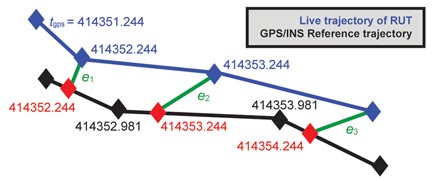
By Ruizhi Chen, Heidi Kuusniemi, Yuwei Chen, Ling Pei, Wei Chen, Jingbin Liu, Helena Leppäkoski, Jarmo Takala
Currently, no single technology, system, or sensor can provide a positioning solution any time, anywhere. The key is to utilize multiple technologies. We are now exploring a multi-sensor multi-network (MSMN) approach for a seamless indoor-outdoor solution. Its hardware platform is described in the previous article. The digital signal processor (DSP) is embedded in the GPS module. All sensors are integrated to the DSP that hosts core software for real-time sensor data acquisition and real-time processing to estimate user location. A smartphone handset provides wireless network measurements.
Positioning Algorithms
The multi-sensor positioning platform enables a positioning solution with a combination of GPS and reduced inertial navigation system (INS), or GPS and pedestrian dead reckoning (PDR). The reduced INS consists of a 3D accelerometer and a 2D digital compass, as a low-cost alternative to augment GNSS positioning. The reduced INS combined with GPS uses a loosely coupled Kalman filter for data integration, while the combination of PDR and GPS uses algorithms for estimating the position change with pedestrian step-length estimation.
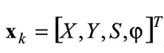
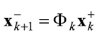
PDR. The PDR solution uses human physiological characteristics, implemented in a local-level frame, with equations:
where k denotes the current epoch, Y is the coordinate in East direction, X is the coordinate in North direction, S is step length, and φ is the heading.
The PDR positioning algorithm includes step detection, step length estimation, determination of heading, and positioning.
To achieve an accurate heading, compass measurements are corrected with an empirical online estimated error model, which requires some training data.
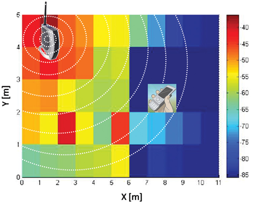
WLAN and Bluetooth. Figure 1 describes the basic concept of the WLAN or Bluetooth locating solution using a fingerprint database approach. The circles around the access point (AP) in the figure represent the radio coverage area and the color the signal strength. This radio map is a simplified example representing measurements from just one AP.
FIGURE 1. Sample WLAN or Bluetooth fingerprint map, in meters.
For the fingerprinting approach, the received signal strength indicators (RSSIs) are the basic observables. The whole process consists of a training phase and a positioning phase. During the training phase, a radio map of probability distribution of the received signal strength is constructed for the targeted area. The targeted area is divided into a matrix of grids, and the central point of each grid is referred to as a reference point. The probability distribution of the received signal strength at each reference point is represented by a Weibull function, and the parameters of the Weibull function are estimated with the limited number of training observation samples. Based on the constructed radio map, the positioning phase determines the current location using the measured RSSI observations in real time.
Given the observation vector , the problem is to find the most probable location (l) with the maximized conditional probability , maximized by Bayesian theorem as:
We applied an assumption of Hidden Markov Models (HMM) to represent the pedestrian movement process. The locating problem is then translated into finding such a state sequence (locations) that is most likely to have generated the output sequence (the measured RSSIs) assuming the given HMM model. The Viterbi algorithm typically solves these kinds of problems efficiently. This study also utilizes the Viterbi algorithm to trace the user trajectory.
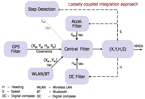
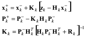
MSMN. The general integration scheme combining the GPS output, sensor measurements, WLAN, or Bluetooth output, and their variance estimates is depicted in Figure 2. A simplified representation of the central filter combining different input sources can be described with typical Kalman filter equations. The measurement model is zk= Hkxk+vk where the state estimate vector is ,
with X, Y, and φ as previously defined, and S the user horizontal velocity (speed). The measurement vector is given as
where g refers to GPS, W to WLAN/Bluetooth, acc to accelerometer, and dc to digital compass. The matrix Hk is the design matrix of the system and the vector vk is the measurement error vector.
FIGURE 2. Integration scheme for multi-sensor, multi-network positioning approach
The recursive sequence includes prediction and update steps. The prediction step includes the typical equations of
and
while the update step includes
Indoor Test Results
A field test has been carried out on a sports field, described in the accompanying article (see Going 3D). An indoor test was carried out in an office-building corridor, but the test started and ended in an outdoor terrace area. During the test, the indoor corridor was covered with eight WLAN and three BT APs.
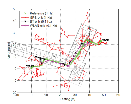
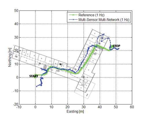
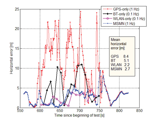
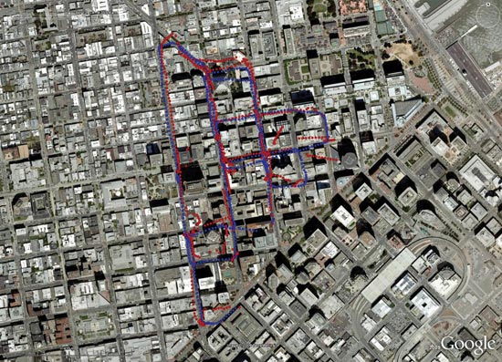
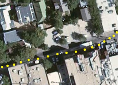
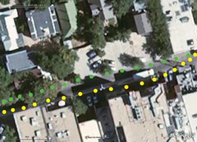
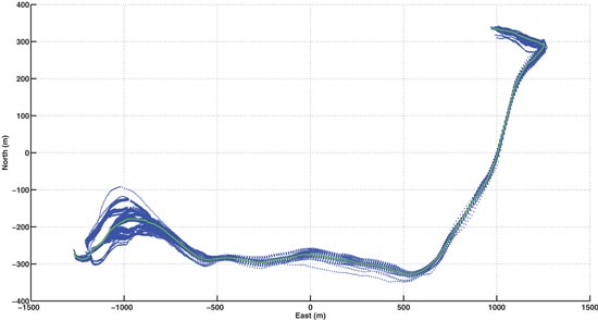
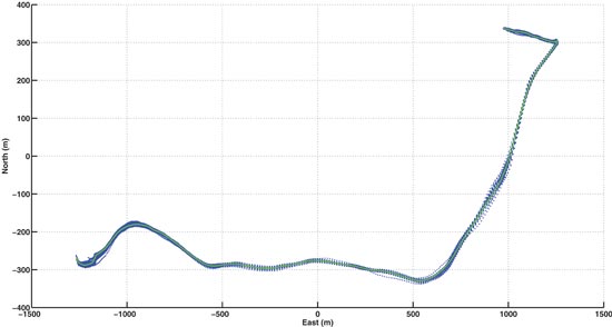
Figure 3 shows the positioning results of the GPS-only (red), Bluetooth-only (black), and WLAN-only (magenta) solutions; Figure 4 shows that of the integrated multi-sensor multi-network (MSMN) solution (blue) for an outdoor-indoor-outdoor test. A reference trajectory is in green in both figures and building outlines in grey. The position update rate achievable by the WLAN and Bluetooth fingerprinting approach is only 0.1 Hz whereas the GPS-only and the integrated MSMN solutions are obtained every second and thus have a higher availability.
FIGURE 3. Pedestrian test results with GPS-only, BT-only, and WLAN-only positioning approaches with respect to a reference trajectoryFIGURE 4. Pedestrian test result with the multi-sensor multi-network positioning approach with respect to a reference trajectory
Figure 5 shows the horizontal errors obtained with the different positioning solutions over time in the indoor test. A mean horizontal error of 2.2 meters was achieved with the WLAN solution. The Bluetooth solution is not as accurate as the WLAN solution, due to the smaller amount of BT APs; it achieved a mean horizontal error of 5.1 meters. When moving inside the corridor, the GPS solutions are used for the MSMN integration only with very low weights due to their poor quality. GPS is mainly used as a source of location outdoors where the test starts and ends. The mean horizontal error of the GPS-only solutions during the whole test is 8.4 meters. WLAN- and Bluetooth-derived locations and the self-contained sensors are the main sources used inside the building for the MSMN positioning solution: the mean horizontal accuracy o
btained with MSMN is 2.7 meters with a solution availability of 1 Hz.
FIGURE 5. Horizontal errors of GPS-only, BT-only, WLAN-only and the MSMN positioning approaches with respect to time in the pedestrian indoor test
The MSMN solution obviously performs much better than a GPS-only solution indoors. The track of the pedestrian walking inside the corridor can be identified clearly, which is not the case with typical approaches of GPS-only or GPS/low-cost sensors. WLAN fingerprinting provides good position accuracy indoors, but the MSMN solution provides the best result when taking into account positioning accuracy and the solution availabilities in both time and space domains.
Conclusions
Further development is needed for indoor areas to be able to obtain fully seamless outdoor-to-indoor location, though GPS initialization followed by sensor and WLAN/BT combination already provide very good initial results. Additional sensors and more refined pedestrian-specific algorithms will be added to further improve the positioning accuracy.
To enrich user experience of location-based services and personal navigation, three-dimensional models such as those used in urban planning are added to a smartphone platform, without the requirement of additional hardware.
Most current map applications for smartphones and other devices providing location-based services (LBS) are based on two-dimensional maps. Three-dimensional (3D) city models are widely used in applications such as engineering design, environmental modeling, and urban planning. Adapting such models for use in smartphones would make it possible to render 3D scenes in real time, enriching contents and user experience for personal navigation and LBS. A delimited yet large-scale event such as the upcoming 2010 World Exposition in Shanghai provides a promising area for system development and testing.
3D visualization consumes a large amount of computing power, and most of the current successful applications run in a PC environment, as does the Google Earth 3D application. It is still a very challenging task to implement 3D visualization in an embedded system such as a smartphone.
This article presents an entire 3D personal navigation system based on a smartphone platform, the Nokia S60 platform. The study covers the following aspects:
3D personal navigation and LBS service in a smartphone
3D city modelling, and
multi-sensor positioning.
The objectives of the work include prototyping an entire handset-based 3D personal navigation and LBS system utilizing WLAN/Bluetooth positioning technologies, handset built-in GPS/AGPS, and 3D modeling and visualization (basic demonstration scenario), as well as presenting a multi-sensor positioning (MSP) platform in addition to the handset software (advanced demonstration scenario).
3D Personal Navigation and LBS
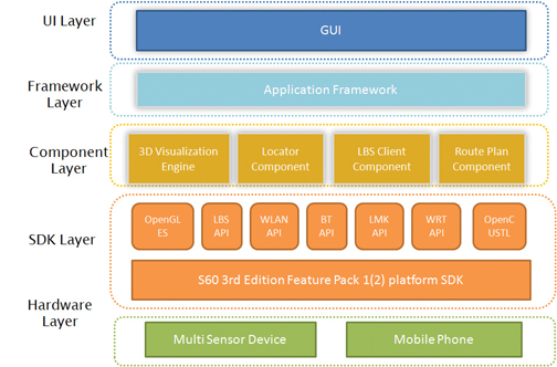
No additional hardware is added to the Nokia Series 60 (S60) smartphone platform to achieve the 3D visualizations or other functions in the software. Figure 1 demonstrates the functionalities and features available in the 3D viewing of the LBS software. Figure 2 shows the general architecture of the software.
FIGURE 1. Functionalities of the 3D LBS softwareFIGURE 2. General architecture of the 3D personal navigation and LBS software
The software development work focuses on the UI layer, framework layer, and component layer. The software mainly includes the following components:
the 3D visualization engine based on OpenGL ES,
the route plan component,
the locator component,
the LBS client component, and
UI and framework.
Most of the challenging tasks are included in the development of the elements in the component layer, especially in the development of the 3D visualization engine based on the OpenGL ES API that is available from the S60 platform SDK (Software Development Kit). The high-level 3D visualization engine architecture covers the interface layer, the core engine layer, and the data management layer. The first one is responsible for cross-component functional communication, request handling, and data exchange. It provides users with the 3D scene visualization functionalities to access the core engine layer via a single class called NaviSceneControl, which includes all the operations of the 3D visualization: scene zooming, view angle rotating, scene and cursor moving, and selecting route planning and virtual navigation.
The core engine layer takes care of the 3D scene visualization computation and model object management. To enable the 3D visualization for a large region, the objects in the scene are classified into two categories in this layer. One is the 3D models like buildings, trees and poles, while the other is texture of land surface, which consist of ortho-rectified digital aerial photos. All the objects are processed as tiles according to the incoming parameters from the interface layer. Therefore only a small subset is loaded dynamically instead of the whole data.
The data management layer accesses the 3D models and ground-texture images persistent on the flash disk of the mobile phone through an independent thread. To reduce the data size of the 3D models, the original .3ds file created from 3D Max Studio software is compressed to fulfill the requirements of the mobile device.
A simple route plan component is implemented in the software to enable to the user to find and view the route to his or her destination. In order to be able to show the entire route, the calculated route will be displayed on top of a 3D view with a downward camera at a high altitude. The 3D scene in this case looks like an orthoimage. An orthoimage shows objects in the perpendicular view to the projection plane of the objects.
The locator component aggregates the positioning information either from the built-in positioning sensors in the smartphone, a GPS receiver, and a WLAN (Wireless Local Area Network) or a Bluetooth chip, or any external positioning device, such as also the multi-sensor positioning (MSP) device developed in this project. It forwards the positioning information including the location and heading information to the route plan component and the 3D visualization engine to accomplish the navigation functions.
The purpose of the LBS client component in the handset software is to access the LBS server.
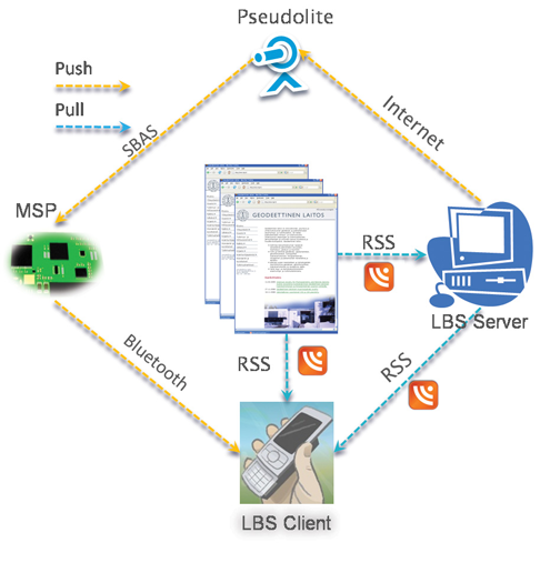
Figure 3 shows the overview of the mechanism for delivering the location-based services. The services are classified into two categories: the static services and the dynamic services. The static services include those services that are not changing in time. For example, POIs (points of interest) belong to this category of service. The static services are stored in a database that can be downloaded from the Internet by the users in advance. The users can store the database in the memory card of the phone before running the 3D personal navigation and LBS software. With this approach, it saves the data transmission fee for the end-users when accessing the LBS. The dynamic services cover those services that change in time. For example, a piece of real-time news is one of the typical dynamic LBS. For accessing the dynamic LBS, the Really Simple Syndication (RSS) technology is adapted in our implementation.
FIGURE 3. Mechanism for delivering location-based services and information
The LBS client component is implemented so that the handset will pull automatically the news in the background in real time via a widget reader embedded in the LBS client component. Whenever new information is uploaded to the LBS server or to the registered web pages, mobile users will be notified.
In addition to RSS technology, another approach to broadcast LBS information is considered in the system: to disseminate the LBS information via an SBAS (satellite-based augmentation system) pseudolite. The dynamic LBS information (e.g., a short message) can be first encoded into a user-defined SBAS message. The message encoded is then sent to a pseudolite from which the message is broadcast. The corresponding SBAS message can, in fact, be received by any SBAS-enabled receiver located within radio coverage area of the pseudolite. However, the encoded LBS message can be decoded only with the receiver that has a special firmware, developed in this case by the Finnish Geodetic Institute (FGI). Having received and decoded the LBS messages transmitted from the pseudolite with a dedicated receiver, for example the MSP device part of the more advanced demonstration scenario of the project, the content of the message is then encoded to a user-defined NMEA (National Marine Electronics Association) message and transmitted to a mobile phone in the vicinity via a Bluetooth connection as shown in Figure 3. This solution of LBS data distribution is available only to a very limited number of users with receivers carting a special firmware developed by FGI.
3D City Modeling
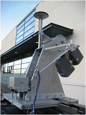
Due to the memory limitations of a mobile phone, there are certain requirements for the 3D models applied. In our study, a test scene for model reconstruction is focused on a street in Espoo, Finland, in an ordinary residential area. A vehicle-borne mobile mapping system ROAMER (see photo) developed by FGI performed the data acquisition. It consists of a carrying platform, a positioning and navigation system, and a 3D laser scanner system. With the ROAMER system, visible objects can be measured with an accuracy of a few decimeters with a maximum vehicle speed of 50–60 km/hour, and the data for the desired objects can be collected within the range of several tens of meters.
ROAMER vehicle-based mobile mapping system.
A large amount of data is produced from the system, and noise and outlier points are needed to be removed. Valid data is classified into different point groups using an automatic algorithm developed by FGI. These point groups include buildings, trees, roads, and poles. Models are then reconstructed based on these classified point groups.
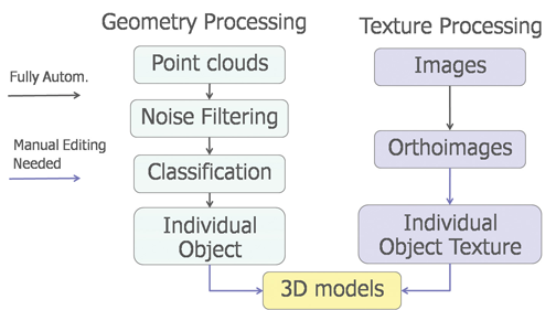
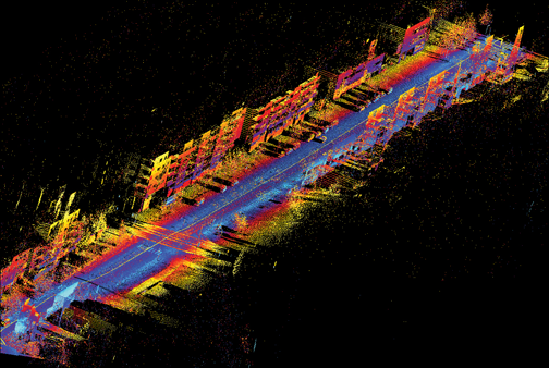
Modeling methods are developed to meet the application requirements of personal navigation: small model size, high accuracy, and good visual appearance. Small model size is achieved by simplified object geometry and reduced texture resolution. Model accuracy is controled by extracting building outlines from a classified point cloud and overlapping with the final 3D model. The model completeness is checked by comparing the resulting model with original images. Good visual effect is realized by applying photo-realistic texture. Photo-realistic texture provides rich information for the 3D scene reconstructed. Figure 4 presents the total process of the 3D modeling, in which only the individual object texture and the final model constructions require manual editing. Figure 5 shows the raw data retrieved and Figure 6 presents the final 3D models of the test area.
FIGURE 4. The process of 3D modelingFIGURE 5. Raw data retrieved from the test area with FGI’s ROAMER systemFIGURE 6. Reconstructed 3D scene of the test area
To import the final 3D models to a mobile phone, the size of an individual model is restricted to less than 100 kb. To optimize model size, a row of buildings is divided into several building blocks.
Multi-Sensor Positioning
As long as open-sky satellite-signal conditions are available, there are no problems to locate a mobile user with the built-in GPS receiver of a smartphone with a positioning accuracy of a few meters. However, most popular location-based services occur in GNSS-degraded environments such as in indoor environments and urban canyons. Locating a mobile user seamlessly any time anywhere under any circumstance is still a very challenging task, especially to implement such an indoor/outdoor positioning solution in a digital signal processor (DSP) platform.
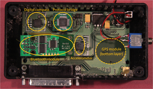
FGI is now developing a DSP-based multi-sensor positioning platform to approach a seamless indoor/outdoor locating solution. The platform consists of a GPS module, a 3D accelerometer, and a 2D digital compass (Figure 7). A DSP is embedded in the GPS module. All sensors are integrated to the DSP that hosts a core software for real-time sensor data acquisition and real-time processing to estimate user’s location.
FIGURE 7. Hardware platform
The multi-sensor platform provides opportunities to investigate the positioning solutions with a GPS/Reduced-INS (Inertial Navigation System) combination or GPS/PDR (Pedestrian Dead Reckoning) combination. The Reduced-INS combination is defined as a combination of a 3D accelerometer and a 2D digital compass, and is a very low-cost approach of sensor augmentation. The GPS/Reduced-INS implementation is implemented in a loosely coupled Kalman filter, while the GPS/PDR algorithm is based on pedestrian-targeted dead reckoning, with heading error and step length estimation methodology.
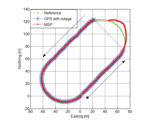
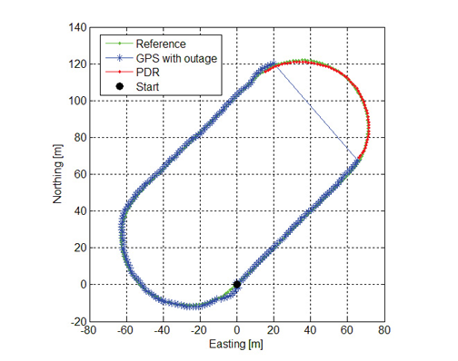
Preliminary tests analyzing both GPS/Reduced-INS and GPS/PDR solutions have been carried out in a sports field on a 400-meter running track. In order to simulate a GPS outage situation, the GPS measurements were ignored for one minute. During this one minute “outage,” the traveling trajectories are estimated with the Reduced-INS solution and the PDR solution. Figure 8 shows the trajectory of the Reduced-INS solution, while Figure 9 shows that of the PDR solution.
FIGURE 8. Trajectory estimation for the 1-minute GPS outage using Reduced-INS approachFIGURE 9. Trajectory estimation for the 1-minute GPS outage using the PDR approach
The Reduced-INS approach provides a reasonable result with a positioning accuracy of about 20 meters at the end of the forced 1-minute GPS outage. The PDR approach provides a better prediction in this case, resulting in only a couple of meters of error after the 1-minute outage of absolute location input from the GPS, because the heading errors are modeled carefully utilizing previous training with data from a previous run along the same track as well as accurate step detection estimation.
Conclusions
The prototype system will be tested and demonstrated at the 2010 World Expo in Shanghai, implemented with a smartphone software package: anyone with a Nokia phone (S60 with built-in GPS and WLAN/BT) can experience the 3D personal navigation and LBS service in the Expo area by downloading and installing the 3D models. The prototype has so far met these challenges: the high performance required of real-time 3D visualization in a smartphone; high positioning availability with acceptable accuracy in indoor and outdoor environments; and the demanding requirements of the 3D models for a small phone, including small model size, high accuracy, and good visual appearance.
Manufacturers
The multi-sensor positioning platform consists of a Fastrax iTrax03 GPS module, a VTI SCA3000-D1 3D accelerometer, and a Honeywell HMC6352 2D digital compass. The ROAMER mobile mapping system consists of a Faro LS 880HE80 terrestrial laser scanner, two AVT Oscar F-810C cameras, and a NovAtel SPAN geo-reference system.
RUIZHI CHEN is a professor and head of the Department of Navigation and Positioning at the Finnish Geodetic Institute, where Heidi Kuusniemi is a specialist research scientist, Juha Hyyppä is a professor and head of the Department of Remote Sensing and Photogrammetry, Risto Kuittinen is director general, Yuwei Chen is a specialist research scientist, and Ling Pei, Lingli Zhu and Jingbin Liu are senior research scientists.
JIXIAN ZHANG is a professor and president of the Chinese Academy of Surveying and Mapping, where Yan Qin and Zhengjun Liu also work as the director of the Department of Research and Development and the group leader in the Institute of Photogrammetry and Remote Sensing, respectively.
JARMO TAKALA is a professor and head of the Department of Computer Systems at Tampere University of Technology in Finland, where Helena Leppäkoski is a researcher.
JIANYU WANG is a professor at the Shanghai Institute of Technical Physics, Chinese Academy of Sciences.
The Leica Builder Series Total Stations, just introduced by Leica Geosystems, is designed for construction contractors or anyone on a construction site requiring an easy-to-operate, full-feature measuring tool.
From simple tasks to professional all-day use, the Leica Builder offers a scaled product family of five different models to meet the varying needs of most construction jobs, Leica said. Contractors can choose from the 100-, 200-, 300-, 400-, or 500-series models.
The Leica Builder Series is designed for non-technical construction professional to easily perform positioning, layout, or dozens of other daily construction-site tasks. To facilitate data transfer, some models feature a USB port-an industry first-while the 500 Series also has Bluetooth functionality.
The Leica Builder Series offers the choice of two operation modes. Contractors can operate in stand-alone mode via the on-board PowerSite construction programs with the memory capabilities to collect, store and download data. Alternatively, an application is available for contractors who prefer to use a data collector. The Builder can be coupled with the Leica DX-10 data collector and Siteforeman software.
On-board PowerSite software is designed specifically for construction applications, eliminating surveying features that contractors may not need, Leica said. Contractors do not require a surveying background in order to use the PowerSite software.
Intended for the construction site, the Leica Builder is designed to withstand dust, water, and other environmental conditions with an IP55 rating.
The entry model Leica Builder 100-Series is an electronic digital theodolite for horizontal and vertical angle measurements. Other models — Leica Builder 200, 300, 400, and 500 — are total stations available with reflectorless and/or prism measurement capabilities, data storage via USB memory stick, and wireless communication for more useful functionality. All instruments are equipped with theft protection and support many different languages of which three can be uploaded and switched at the push of a button. The Leica Builder is delivered packaged in a crush-proof transport case with a set of accessories for out-of-the-box use.
Last week, the U.S. Air Force announced it is reconfiguring the GPS constellation. The Air Force is changing the constellation from a 21+3 configuration to a 24+3 configuration. The result will be more satellites in view, on average.
This is great news for the GPS surveying and GIS mapping user. In my opinion, it was the only achievable short/medium-term solution to the GPS “brownout” problem that has plagued GPS surveying and mapping users for years, and has worsened in recent months.
In short, a GPS “brownout” is a time of the day when a GPS user is unable to utilize his or her GPS receiver because there aren’t enough satellites in view to achieve the desired accuracy. GPS “brownouts” primarily affect high-precision RTK users because that technology requires that the GPS receiver is tracking at least six satellites for a reliable position. With the current GPS constellation, there are times during the day when this is not possible given the satellite configuration and local conditions (obstructions such as trees, buildings, and terrain). This problem puts a serious damper on GPS productivity.
Even though there are currently 30 operational GPS satellites, they are configured in a 24-satellite constellation. Essentially, several satellites are “paired up” so they add no value to users on the ground. They are designated as back-up satellites in case of a failure. I wrote a detailed article on this subject in October 2009 titled GPS Constellation Management: Playing Not to Lose that summarizes the problem.
The New 24+3 Configuration
Announcements from various publications and online newsgroups have different interpretations of the Air Force announcement. Some are emphasizing increased accuracy and others are citing increased coverage in Afghanistan. While both are correct, the major benefit to the surveying/mapping user community is increased worldwide satellite visibility. In other words, more GPS satellites will be in view at a given time during the day.
More satellites in view = greater RTK and mapping productivity.
The reason that increased accuracy is mentioned in the announcement is because PDOP values will be lower in general due to the increase of satellites in view…and there’s a direct correlation between accuracy and PDOP. Just how many more satellites will be in view is not clear yet. I’m working on producing some mission planning charts that will illustrate the benefits of 24+3 compared to 21+3.
The three satellites being repositioned are SVN24, SVN26, and SVN49. SVN24 and SVN26 are two of the oldest satellites (Block-IIA) in the GPS constellation. SVN24 was declared operational in August 1991. SVN26 was declared operational in July 1992. SVN49 is a newer Block II-RM that was launched last March and has never been declared operational due to an anomaly discussed here before. More on SVN49 further down.
The time to reposition each satellite is significant. SVN24, with the furthest distance to travel, began its journey last week and will take 12 months to reach its destination slot according to the Air Force. SVN49 will begin its journey on January 21, 2010, and will take four months (May 2010). SVN26 will begin its transition on February 8, 2010, and will reach its destination slot in approximately three months (May 2010), according the Air Force.
Which Users Will Benefit the Most?
After (and maybe during) the transition, RTK users will see an increase in the number of visible GPS satellites throughout the day. As I mentioned above, I’m still working on producing satellite visibility charts to better and more accurately illustrate this, so stay tuned. Of course, the benefit is going to vary depending on where you are located.
Another group who will benefit is GIS mapping users, especially those working in difficult GPS conditions such as in forestry, urban/municipal areas, and areas where there is rugged terrain. An increased number of GPS satellites in view will allow GIS mapping users to operate in areas where it may not have been possible before and perform better in areas that were difficult.
Consumer GPS users will benefit the least. Even during times of GPS “brownouts,” the pushback from consumer GPS has been minimal. Automobile navigation systems perform without a hiccup for the most part and handheld receivers behave reasonably well. The primary reason is that both of those types of receivers aren’t selective about the satellite signals they accept. Accuracy is way down the list of important design features in those receivers. That’s not the case with RTK and professional GIS mapping receivers. RTK and GIS mapping receivers require high-quality measurement data from GPS satellites.
Will RTK Users Still Need GLONASS?
Certainly, GPS-only (non-GLONASS) RTK users will see an increased benefit with the 24+3 configuration, particularly those who are operating in relatively clear-sky environments like precision agriculture. However, as we’ve seen with this technology, users will keep pushing the GNSS envelope to use it in marginal conditions where GPS 24+3 won’t be enough. GLONASS will still contribute more satellite measurements, on average, than GPS 24+3. Therefore, GLONASS will still be a desirable feature.
But, I think we may see mainstream GNSS receiver manufacturers selling the GLONASS option at a lower price (or offering it for free) as it will be required in fewer instances. Russia is continuing to launch GLONASS satellites three at a time with the most recent launch being in December 2009 and the next scheduled one being later this spring.
SVN49 – What No One Is Talking About
One of the three GPS satellites being repositioned for 24+3 is SVN49. If you’ve kept up with the GPS constellation over the past six months, no doubt you’ve read about the SVN49 problem. It was launched last March and still hasn’t been declared healthy due to an irreparable problem. There has been much debate about what to do with SVN49. You can read about it here and here and here.
Most likely, the problem that SVN49 has will not affect RTK users. In other words, if SVN49 is set healthy, RTK users will be able to utilize it like the other normally operating GPS satellites.
However, GIS mapping users won’t benefit from SVN49. The Federal Aviation Administration (FAA) has said it won’t incorporate corrections for SVN49 in WAAS. Although the U.S. Coast Guard (USCG) and Department of Transportation (DOT) haven’t commented, I doubt they will broadcast DGPS corrections for SVN49 either. For code phase post-processing, I doubt manufacturers will modify their post-processing software to accommodate the SVN49 anomaly.
So, for GIS mapping users, it’s likely going to be a 24+2 configuration instead of a 24+3 configuration.
Either way, this is good news across the board for the GPS surveying and mapping user community.
I agree with what Don Jewell wrote in his column recently, that this subject is going to be written about and discussed a lot over the next few
months as SVN26 and SVN49 are repositioned, and over the next year as SVN24 reaches its destination.
I’ve intended to write about the 2008 Federal Radionavigation Plan (FRP) for quite some time. It is an important document because it is the official policy document that drives the United States’ radio navigation (including GPS) program planning. According to the FRP, it includes the introductions, policies, radionavigation system user requirements, system descriptions, and operating plans of various radionavigation systems. The FRP is updated biennially. The 2008 FRP was approved in January 2009.
The FRP preface states that it is prepared jointly by the Department of Defense, Department of Homeland Security, and Department of Transportation with assistance from other government agencies. The document covers radionavigation systems used by both the civilian and military communities. It does not cover radionavigation systems used exclusively by the U.S. military.
The FRP is a fascinating document because it encompasses GPS, GPS augmentation systems, and “back-up” systems. In this column, I’m going to extract several statements from the FRP and comment on them. If you’d like to read the FRP in full (184 pages), you can do so here. Briefly, the FRP includes the following navigation technologies: GPS, WAAS, DGPS, LORAN, and VOR/DME/TACAN/ILS/MLS/NDB (all aviation-oriented).
By way of background and according to the FRP, the first version of the FRP was released in 1980 as part of a Presidential Report to Congress.
For the remainder of this column, I’ll provide quotes from the FRP that I think are relevant and add some commentary.
From the executive summary:
“A major goal of DoD and DOT is to ensure that a mix of common-use (civil and military) systems is available to meet user requirements for accuracy, reliability, availability, continuity, integrity, coverage, operational utility, and cost; to provide adequate capability for future growth; and to eliminate unnecessary duplication of services. Selecting a future radionavigation systems mix is a complex task, since user requirements vary widely and change with time. While all users require services that are safe, readily available and easy to use, unique requirements exist for military as well as civil users. For example, the military has more stringent requirements including performance under intentional interference, operations in high-performance vehicles, worldwide coverage, and operational capability in severe environmental conditions. Similarly, civil users desire higher accuracy and integrity for future highway, rail, and other safety-of-life applications. Cost is always a major consideration that must be balanced with a needed operational capability.”
EG Comment: As I did, you may think the “civil user desires” described in the executive summary are a small subset of actual consumer users, and that’s true. But, it’s important to remember that this document is focused on U.S. government users rather than commercial users.
However, it does raise a point about the consideration given to civilian users when program decisions are being made regarding GPS such as features, satellite launch schedules, ground infrastructure, and constellation management. I’m sure when a congressperson, who is making decisions regarding budgets, is researching the subject he or she will read this executive summary. The statement “civil users desire higher accuracy…” will mislead the reader. While there is a demand for high accuracy in the commercial civil user community, there is a much larger demand for products in the low and medium accuracy commercial markets.
While I’m not criticizing the executive summary for being incorrect, it seems to me that the people who control the purse strings (Congress) may not be given enough information to grasp the “big picture” regarding the GPS user community.
“Interoperability considerations —
“National and international radionavigation systems are sometimes used in combination with each other or with other systems. These combined systems are often implemented to provide improved or complementary performance. In the case of GPS, the USG encourages future interoperability with foreign space-based PNT systems for civil, commercial, and scientific uses worldwide. Examples of existing or future foreign space-based PNT systems are Russia’s Global Navigation Satellite System (GLONASS), the European Union’s Galileo, Japan’s Quasi Zenith Satellite System (QZSS), China’s Compass, and India’s Regional Navigation Satellite System (RNSS). Properly designed receivers that take advantage of these systems may benefit from additional satellite signals, increased redundancy, and improved performance over that obtained from just one system alone. A critical aspect of system interoperability is ensuring compatibility among radionavigation services. For example, the USG has concerns about radionavigation signal structures that could adversely impact the military and civil use of GPS. The USG has also fostered the use of interoperable augmentations through its adherence to international standards for DGPS and space-based augmentation system services.These include Maritime DGPS and the Wide Area Augmentation System.”
EG Comment: I have to say that the U.S. government has done a good job in the area of interoperability. In the 2001 Federal Radionavigation Plan, interoperability wasn’t discussed nearly to the degree it is in the 2008 FRP.
From the 2001 FRP: “Radionavigation systems are sometimes used in combination with each other or with other systems. These combined systems are often implemented so that a major attribute of one system will offset a weakness of another.…a few manufacturers have of navigation and positioning equipment have developed combined GPS/GLONASS receivers to take advantage of these benefits. Some receivers are on the market with others in the planning stage.”
From 2001 to 2008, the U.S. government’s position has morphed from recognizing that some GPS/GLONASS receivers exist to actually encouraging interoperability with all “foreign-based PNT systems for commercial, civil, and scientific uses worldwide.” That’s quite a transformation.
“General policy statement —
“As the full civil potential of GPS services and its augmentations are implemented, the demand for services provided by other Federally provided radionavigation systems is expected to decrease. The USG will reduce non-GPS-based radionavigation services with the reduction in the demand for those services. However, it is a policy objective of the USG not to be critically dependent upon a single system for PNT. The USG will maintain back-up capabilities to meet: (1) growing national, homeland, and economic security requirements, (2) civil requirements, and (3) commercial and scientific demands. Operational, economic, safety, and security considerations will dictate the need for complementary PNT systems. While some operations may be conducted safely using a single radionavigation system, it is Federal policy to provide redundant radionavigation service where required. Backups to GPS for safety-of-life navigation applications, or other critical applications, can be other radionavigation systems, or operational procedures, or a combination of these systems and procedures to form a safe and effective backup. Backups to GPS for timing applications can be a highly accurate crystal oscillator or atomic clock.”
EG Comment: I wrote to someone the other day about this. Back-ups to GPS is a serious issue. I think very few would argue that it’s not. The reality is that
there is no single back-up for GPS. It depends on the application. In aviation, it’s maintaining a minimal infrastructure of VOR/DME/ILS rather than Loran, according to the FAA. In maritime, it’s the legacy visual aids and charts according to the U.S. Coast Guard. For high precision users, it’s legacy technology like optical instruments and new technology like Locata and pseudolites.
“GPS backup —
“With respect to transportation to include aviation, commercial maritime, rail, and highway, the DOT has determined that sufficient alternative navigation aids currently exist in the event of a loss of GPS-based services, and therefore Loran currently is not needed as a back-up navigation aid for transportation safety-of-life users. However, many transportation safety-of-life applications depend on commercial communication systems and DOT recognizes the importance of the Loran system as a backup to GPS for critical infrastructure applications requiring precise time and frequency.”
EG Comment: The continuing Loran saga.
“Civil Signals —
“In addition to the L1 Coarse/Acquisition (C/A) signal, the USG will add three additional coded signals to support future civil applications:
• L1C, frequency 1575.42 MHz, providing better performance than the current C/A signal being used by civilian receivers;
• L2C, frequency 1227.6 MHz; and
• L5, frequency 1176.45 MHz, to meet the needs of critical safety-of-life applications, such as civil aviation.
“The L1C signal is designed to be interoperable with the European Galileo system and is being promoted as a future world standard for incorporation into Global Navigation Satellite Systems (GNSS). The next generation of GPS satellites, GPS III, will begin broadcasting L1C around 2014.
“The performance specifications in the current SPS PS apply to users of the L1 C/A (1575.42 MHz) signal. As new modernized GPS civil signals (L1C, L2C, and L5) achieve initial operating capability (IOC), performance standards for services utilizing these signals will be developed.”
EG Comment: Nothing new here, but the schedule of actually implementing the new civil signals is a moving target. There are only seven satellites broadcasting L2C at this time. The first Block IIF satellite with L5 should launch in the first or second quarter of this year. Satellites broadcasting L1C (Block III) won’t launch until at least 2014 and a full constellation won’t be operational for many years after that.
“Discontinuation of codeless and semi-codeless GPS access —
“As published in the Federal Register on September 23, 2008 (Volume 73, Number 185), the USG commits to maintaining the existing GPS L1 C/A, L1 P(Y), L2C and L2 P(Y) signal characteristics that enable codeless and semi-codeless GPS access until at least 31 December 2020. To enable an orderly and systematic transition, users of semi-codeless and codeless receiving equipment are expected to transition to using civil-coded signals by this date.”
EG Comment: I’ve written a lot about this. You can read some here.
“Military signals —
“Currently, GPS military users are provided P(Y) code signals on L1 and L2. These will be supplanted in the future by the M-Code, the next generation military GPS signal. The first GPS Block IIR-M satellite began broadcasting M-Code in September 2006. M-Code will significantly improve exclusivity of access because, in addition to being encrypted, it will be spectrally separate from civilian signals and other radionavigation satellite service signals, thereby enabling U.S. navigation warfare operations through spectral separation. Navigation warfare involves protecting U.S. and allied use of GPS while simultaneously preventing hostile forces access to GPS services and preserving peaceful civil GPS use outside of an area of military operations. The M-Code will permit higher power operation than the present signal design and will facilitate localized tactical denial of GPS civil signals to prevent their use by hostile forces. Military GPS receivers, when tracking the encrypted military signals, are much more resistant to interference than commercial GPS equipment. The newest generation of military GPS receivers that can access military GPS signals directly are even more resistant to interference; however, future improvements in signal availability and receiver performance will continue to be necessary.”
EG Comment: The key phrase is “localized tactical denial of GPS civil signals…”. Wow, what can I say about that? Come on GLONASS/CDMA, and Galileo, hurry up!
“Military use of GPS civil signals —
“DoD does not have an operational requirement to use the GPS civil signals, designated L1C, L2C, and L5, or the Wide Area Augmentation System (WAAS), with the exception of the Army validated WAAS requirement documented in the Global Air Traffic Management (GATM) Operational Requirements Document (ORD). Since DoD policy prohibits the use of civil signals or augmentation systems in wartime environments and dual equipage is not fiscally practical, type approval of military aviation receivers is required to eliminate the need for civil GPS equipage on military aircraft. This will provide an enhanced capability to span the operational environment for military aviation—from flight in civil airspace in peacetime to combat operations worldwide. Commercial operators of Civil Reserve Air Fleet (CRAF) airframes may elect to equip with L5 and/or WAAS if there is a demonstrated.”
EG Comment: Interesting.
“Mitigating Disruptions in Aviation Operations —
“A loss of GPS service, due to either intentional or unintentional interference, in the absence of any other means of navigation, would have varying negative effects on air traffic operations. These effects could range from nuisance events requiring standard restoration of capabilities, to an inability to provide normal air traffic control service within one or more sectors of airspace (the NAS is divided into hundreds of air traffic control sectors. A single air traffic controller has the responsibility to keep aircraft safely separated from one another within each sector and from other sectors. Sector dimensions vary, and are established based on predominant traffic flows, altitude, and controller workload) for a significant period of time.
“In addition to FAA plans of retaining a minimum network of VOR, DME, and ILS facilities to serve as a backup to GPS for the
near future, several other solutions have been identified to help mitigate the effects of a satellite navigation (SATNAV) service disruption:
“The L5 civil frequency planned for GPS will help mitigate the impacts of both solar activity and unintentional interference, but it may be 2018 before a full constellation of dual-frequency satellites (L1 and L5) is available. The dual frequency capability with L5 will address ionospheric scintillation by enabling receivers to calculate
actual ionospheric corrections, thereby preserving LPV capability during severe ionospheric storms.
Modern transport-category turbojet aircraft with inertial systems may be able to continue navigating safely for a period of time after losing radionavigation position updating depending on the route or procedure being flown. In some cases, this capability may prove adequate to depart an area with localized jamming or proceed under visual flight rules during good visibility and high ceilings, however, inertial performance without radionavigation updates degrades with time and will eventually fail to meet airspace requirements.
Integrated GPS/inertial avionics having anti-jam capability could reduce the area affected by GPS jamming or unintentional interference. Industry research is proceeding to develop this technology, with an expectation that it might be marketed to the general aviation community at some point in the future.
Users may have an option to equip with instrument flight rules (IFR)-certified Loran avionics, pending the improvements needed to achieve a nonprecision instrument approach capability with eLoran. A combined eLoran/SATNAV receiver could provide navigation and nonprecision instrument approach service throughout any disruption to SATNAV service.
EG Comment: This is a good description of the GPS strategy for aviation operations. But, honestly, if there’s a disruption once the National Airspace System (NAS) is fully reliant on GPS, it’s hard to see there not being major, major hiccups in the air traffic system.
“Mitigating disruptions in land operations —
“Surface transportation users currently use radionavigation services from GPS and its augmentations to supplement other available nonradionavigation systems. Under this operational paradigm, users seamlessly use other existing techniques to mitigate both the short-term loss of GPS due to obstructions and the longer-term loss due to failed on-board user equipment and adverse operating environments. In future applications, accuracy requirements are expected to become much more stringent, and GPS and its augmentations are likely to play a more critical role. The loss of GPS and its augmentations will be carefully evaluated within the overall operational environment to ensure continued safe and efficient operation of the land transportation system.
“Surface transportation agencies are working with industry to ensure that safety critical systems that use GPS and its augmentations consider the loss of these radionavigation services and are able to mitigate its effects in order to continue safe and efficient operation of the nation’s surface transportation infrastructure. This is accomplished today by outreach to user groups and local transportation agencies and defining minimum operational or functional standards. In the future, training for application developers, state and local highway and transit agencies, and motor carriers on the operational capabilities of GPS as well as what to do when failures occur may be necessary. Finally, since it is expected that signal availability from GPS may not be adequate for surface users experiencing canopy/urban obstructions, alternate systems that perform a verification test on the GPS navigation solution and that support continued operation in the event of a loss of GPS will be employed in a system-of-systems configuration.”
EG Comment: A great argument for multi-constellation receivers.
“Mitigating disruptions in non-navigation applications —
“Common positioning applications include: surveying and mapping; precision agriculture; emergency response and law enforcement; fire services; environmental resource management; utility location and management; asset inventory and management; and logistics. These applications have a highly variable duration and involve sporadic areas of operation. Because of the flexible character of positioning applications, operations will typically be halted until the GPS or GPS Augmentation signal is restored in an area. Optical and inertial surveying equipment are back-up options that could meet the accuracy requirements of these applications, depending on the capabilities and preparation of these operators.”
EG Comment: Multi-constellation receivers have already proven their value in non-navigation applications.
“Operating Plans – GPS —
“DoD will provide a 48-hour advance notice of changes in the constellation operational status that affect the service being provided to GPS SPS users in peacetime, other than planned GPS interference testing. The USG provides notification of changes in constellation operational status that affect the service being provided to GPS users or if a problem in meeting performance standards is anticipated. In the case of a scheduled event affecting service provided to GPS users, the USG will issue an appropriate Notice Advisory to Navstar Users (NANU) at least 48 hours prior to the event, in accordance with the GPS Standard Positioning Service Performance Standard (Ref. 9).
“Coordination of planned interference testing activities nominally begins 60 days before testing events. Users are notified by the USCG as soon as an activity is approved, and by FAA typically not earlier than 72 hours before an activity begins. DoD notice will be given to the USCG Navigation Information Service (NIS) and the FAA Notice to Airmen (NOTAM) system. The NIS and NOTAM systems will announce unplanned system outages resulting from system malfunctions or unscheduled maintenance.
“GPS will be the primary Federally provided radionavigation system for the foreseeable future. GPS will be augmented and improved to satisfy future military and civil requirements for accuracy, coverage, availability, continuity, and integrity. Current policy states that DoD will maintain a nominal 24-satellite constellation, and that replacement satellites will be launched on an anticipated need to maintain the constellation as satellites age and ultimately fail.”
EG Comment: Good policy statement on notification to civil users. You can sign up to receive NANU’s here.
Note the statement regarding maintaining a 24-satellite constellation. There are currently upwards of 30 operational GPS satellites. That’s a healthy number, but the problem is that they are still positioned as 24 satellites. In other words, several are “paired up” so the effective constellation is still only 24. There is discussion within the USG about repositioning some of the satellites to optimize the constellation and improve coverage. More on that soon I hope.
“Maritime and nationwide differential GPS —
“USCG began development of the MDGPS system in the late 1980s to meet the needs of the Coastal and Harbor Entrance and Approach (HEA) phases of
navigation and to enable automated buoy positioning. MDGPS service was certified fully operational in March 1999 after the network met the performance standards required for HEA navigation. PL 105-66, Title III, § 346 (111 Stat. 1449) authorizes the Secretary of Transportation to improve and expand the USCG’s MDGPS into a Nationwide DGPS, or NDGPS, by adding an inland segment. RITA coordinates this inland program and is acting chair of the NDGPS Policy and Implementation Team. Today, multiple Federal agencies, several states, and scientific organizations are cooperating to provide the combined national DGPS utility, with plans to complete NDGPS system coverage throughout the lower 48 states.
“Each NDGPS facility meets all operating parameters established to qualify a MDGPS facility for operational availability, as established by USCG. NDGPS was not designed to meet aviation integrity requirements.
“In addition to providing a real-time broadcast of differential corrections, the U.S. DGPS services provide a robust operational backbone to the DOC’s CORS application for post-processing survey applications and Webenabled location solutions, the National Weather Service’s Forecast Systems Laboratory for short-term precipitation forecasts, and the University NAVSTAR Consortium (UNAVCO) for plate tectonic monitoring. Where operational considerations allow, additional operational capability may be added, such as the broadcast of navigational or meteorological warnings and marine safety information (i.e., NAVTEX data) to support safe navigation at sea.
“Currently 39 USCG and nine USACE broadcast sites provide service for maritime coverage CONUS, the Great Lakes, Puerto Rico, portions of Alaska and Hawaii, and portions of the Mississippi River Basin. The inland NDGPS segment complements the MDGPS segment and is planned to provide dual coverage of the CONUS and selected portions of Hawaii and Alaska as a combined national DGPS utility. There are currently 38 DOT sponsored sites in the NDGPS network providing 92 percent of the contiguous 48 states with single coverage and 65 percent with dual coverage. The combined DGPS service will provide uniform coverage of the CONUS and portions of Hawaii and Alaska, regardless of terrain, or man-made and other surface obstructions. This coverage is achieved by using a medium frequency broadcast optimized for surface applications. The broadcast has been demonstrated to be sufficiently robust to work throughout mountain ranges, difficult terrain and other obstructions. The combined DGPS service will provide a highly reliable GPS integrity function to users to meet the growing requirements of surface users (transportation, precision agriculture, natural resources and environmental management, emergency management and response, and surveying and construction communities).
“As each new Nationwide site is added to the DGPS network, it is evaluated and tested to ensure that it meets the full operational capability specifications commensurate with a safety of life service. Once a site is declared fully operational, the site is monitored and maintained by the USCG to ensure support for safety applications. System coverage for a specific location can be obtained from the USCG Navigation Center (NAVCEN) website, http://www.navcen.uscg.gov.
“The two major deployment milestones have been established as nationwide single station coverage and nationwide dual station coverage (CONUS only). Under single station coverage, predicted to occur no earlier than 2010 (pending funding availability), users anywhere within CONUS will be able to receive at least one DGPS differential correction broadcast. The second major milestone is full coverage by at least two DGPS broadcasts, is expected to occur no earlier than 2012.”
EG Comment: This is a great example of where policy and the presidential budget don’t necessarily agree. NDGPS has been on the budget chopping block for several years. At this point, DOT has only budgeted to maintain the existing system…about $4.6M annually for the 38 DOT-sponsored sites. The 39 USCG and nine USACE sites provide safety-of-life service so their budgets are secure.
“High Accuracy NDGPS —
“The HA-NDGPS research program is sponsored by FHWA and FRA to enhance the performance of NDGPS. The first HA-NDGPS station began broadcasting in a test mode in 2001 with funding from the Interagency GPS Executive Board (IGEB). IGEB recognized the potential benefit to many Federal agencies, states, and the general public of having a nationwide high accuracy system. Two HA-NDGPS reference stations are currently operational and providing 10 to 15 cm accuracy throughout the coverage area. Further improvements to accuracy and the development of 1 to 2 second time-to-alarm integrity are anticipated. Once these improvements are complete, a HA-NDGPS standard will be developed.
“To support this, several approaches are being investigated. They can be grouped into three general categories: improved ionosphere and troposphere prediction; increased data throughput to support broadcast of GPS observables; and the addition of pertinent data to the current broadcast.”
EG Comment: The HA-NDGPS program is one that’s been around a long time. It’s a technology in search of an application. The growth of RTK networks threatens to render HA-NDGPS obsolete. An interesting rumor I heard is that DOT is considering streaming NTRIP data from NDGPS and possibly HA-NDGPS. Essentially, that means one could receive RTCM corrections over the internet via Wi-Fi, mobile phone networks, etc.) and eliminate the bulky and expensive beacon receivers required to use NDGPS today.
“Wide Area Augmentation System (WAAS) —
“WAAS, an SBAS operated by FAA, provides increased navigation accuracy, availability, and integrity for aircraft navigation during departure, en route, arrival, and approach operations. Although designed primarily for aviation applications, WAAS is widely available in receivers manufactured for navigation use by other communities.
“FAA commissioned WAAS in 2003. WAAS service supports departure, en route, arrival, and approach operations, including nonprecision approaches and approach procedures with vertical guidance. The WAAS service may support additional capabilities such as advanced arrival and departure procedures (curved and segmented), more efficient en route navigation and parallel runway operations, runway incursion warnings, high-speed turnoff guidance, and airport surface operations.
“WAAS will be modified to utilize the L5 signal provided by modernized GPS satellites, in lieu of the current semi-codeless L2 signal being utilized to determine ionospheric corrections. New dual-frequency WAAS avionics using L1 and L5 will improve the availability of LPV service.
EG Comment: Note that WAAS is bypassing L2C. It says something about the future of L2C and if it’s really needed. That’s another discussion altogether. Like GPS, WAAS, and SBAS in general is being used in many applications beyond its original intent. There are hundreds of thousands (several million if you include the consumer WAAS users) that outnumber by orders of magnitude the number of WAAS users in aviation.
“The U.S. Continuously Operating Reference Station (CORS) System —
“NOAA’s NGS, an element of DOC, has established a CORS system to support non-navigation post-processing applications of GPS, especially precise 3-dimensional positioning at the few centimeter level. More recently, the CORS network has also served the atmospheric science community as a tr
oposphere and ionosphere monitoring network, and it has served the geophysics community as a crustal motion monitoring network. Additionally, the CORS system is being modernized to serve as the foundation for future applications that support real and near real-time positioning (that differ from navigation applications by the lack of redundancy and integrity monitoring required for safety-of-life applications). The CORS system provides code range and carrier phase data from a nationwide network of GPS stations for access by the Internet.
“As of June 2008, data were being provided from more than 1,200 stations. The NGS manages and coordinates data contributions from GPS tracking stations established by more than 200 other groups rather than by building an independent network of reference stations. In particular, use is being made of data from stations operated by components of DOT and DHS that support real-time navigation requirements (mostly WAAS and NDGPS augmentations). These real-time stations make up approximately 17 percent of all CORS stations. Other stations currently contributing data to CORS include stations operated by NOAA, NSF, and NASA in support of crustal motion activities; stations operated by state and local governments in support of surveying and mapping applications; and stations operated by NOAA’s Earth Systems Research Laboratory, in support of meteorological applications. The breakdown of CORS partners is illustrated in Figure 5-1.
“The national CORS system is a GPS augmentation system managed by NOAA that archives and distributes GPS data for precision positioning and atmospheric modeling applications. It serves as the basis for the National Spatial Reference System, defining high accuracy coordinates for all Federal radionavigation systems. Historically, CORS served postprocessing users of GPS, but is being modernized to support real-time users at a similar level of accuracy.”
EG Comment: What can you say about the CORS system other than that it’s a model for other CORS systems around the world. It says something about the success of the program in that it’s allocated an entire page in the FRP.
Phew, there’s more in the FRP I could quote and discuss but I’ve touched on the major items. Hopefully, this gives you an idea of what the USG thinks about when it makes strategic and tactical decisions about the GPS program. However, keep in mind that in many cases policy and budget don’t match, and if there’s a conflict between the two, budgets usually win.
A team will attempt to shatter the world land speed record, with a GPS/GLONASS receiver riding the controls.
photo: GPS/GLONASS
In summer 2010, a team of 44 volunteers will attempt to shatter the world land speed record of 763 miles per hour (2 mph faster than sound) by hitting 800 on the speedometer. To ensure that the North American Eagle takes it to the limit efficiently and safely, the team captures performance data from 70 sensors, locked to position, velocity, and time coordinates by an onboard GNSS receiver.
An old Lockheed F-104, a ’60s era Mach II fighter, rescued from a scrap dealer in Maine seemed to have the mark of greatness somehow still on it, amid the fuselage holes and grafitti. A team of volunteers converted the plane into a supersonic car: one expert machined the solid billet aluminum wheels, another rebuilt the General Electric J-79 engine, another devised a magnetic braking system. Over three years, the team replaced 40 percent of the plane’s skin panels, 5,000 rivets, the front suspension, and the steering and hydraulics systems.
The 56-feet-long, 13,000-pound car features Magna Force Lev-X magnetic brakes, a stock engine that outputs 42,500 horsepower, burning 160 gallons of fuel per minute in afterburner mode, and a backup 52,000-hp engine.
At supersonic speeds, anticipating and controlling the car’s reactions to physical stresses become critical. explains Steve Wallace, data-acquisition engineer: “Stuff happens when you get up to the speed of sound. Shock waves affect the aerodynamic balance of the vehicle, and when you’re flying six inches from the ground, aerodynamic unbalance becomes very important.” Wallace and the team must ensure that the car does not burrow into the ground or lift any of its wheels while in motion; either would be detrimental to record-setting and driver safety.
Accelerometers, strain gauges, piezoelectric sensors, inertial gyros, airspeed and air-pressure sensors, and more all generate streams of data, stored on a laptop computer mounted behind the car’s cockpit. Wallace accesses the system in real time via an Ethernet wireless umbrella of routers mounted on 20-foot-tall towers spaced at 2½-mile intervals alongside a 14-mile track at Black Rock Desert, Nevada. After a test run, he downloads the data to his computer, correlates time and location, then exports to a spreadsheet.
GNSS makes speed measurement more reliable and accurate. “We have a lot of sensors, but one sensor I don’t have is for vehicle speed,” he says. “This is a thrust vehicle; the wheels aren’t driven, so realistically, the wheels are never going as fast as the ground. Measuring airspeed is not a bad way of [measuring vehicle speed], but it’s very noisy. The data are all over the place and you have to do a lot of smoothing and averaging. With GNSS, it’s dead nuts — a great way of getting information I need, fast, without looking at accelerometer data. I can’t think of a more valuable tool to understand what’s happening from a sense of motion of the vehicle in general.
“If we had a $10 million budget, we could buy a ground-tracking radar unit like the Air Force uses, but that ain’t gonna happen. We can get just as good data with this as with a $10 million system, so why go any further?”
The project could provide further practical engineering benefits. The team likens this research to that of the 1960s space program, which benefited development of computers, cellular phones, and microwave ovens.
Manufacturers
A dual-frequency Topcon PG-A1 antenna and Euro 160T OEM receiver collect GPS/GLONASS signals at 20 Hz. A Euro 160T mobile control board rides in the car’s electronics bay. A GB-1000 receiver collects static reference data.
At the end of every year, I devote this column to Directions 2010 in which I discuss significant developments, trends, technologies, and companies in the GNSS industry.
Two years ago, I wrote about the Year of the Who. Not GNSS technology; rather, the people and companies they run.
Last year, I highlighted 2009 as being the Year of the Other GNSS. The little brother of GPS…GLONASS.
I’ve thought a lot about this year’s column. Some have said that next year will be the Golden Year for GNSS with the launch of the first Block IIF satellite, possibly the launch of the first GLONASS-K satellite (broadcasting CDMA), launch of Japan’s first QZSS satellite, launch of a GAGAN geostationary satellite, yada, yada, yada.
The problem with this, as I see it, is that these developments will have very little impact on GNSS users in 2010. All of them have been on the drawing board for years, all have been vetted, and most of them are behind schedule. In a nutshell, it’s beating a dead horse. How many times can one talk about Galileo? Even I get tired of writing about the next satellite launch, the next signal to be broadcast, the next GNSS to be developed, etc.
From a GNSS technology perspective, do you know what excites me? Optimizing the current constellation of satellites that are already in orbit. That’s where the “rubber hits the road.” With a few tweaks of the GPS constellation, our “brownout” periods would largely disappear immediately. No waiting for new satellite launches, no waiting for new GPS receiver technology to purchase. Just like when Selective Availability (SA) was turned off…boom…an overnight difference. Of course, I know it’s not quite as easy as turning off SA, but I think you see my point.
However, even though it’s likely that the Air Force will reconfigure the GPS constellation to reduce the GPS brownouts in 2010, that’s not the focus of this column (although it’s a close second).
Nope. The statement that best defines the GNSS industry for 2010 is one I’ll borrow from Bill Clinton that he used during his campaign for the U.S. presidency in 1992…
”It’s the economy, stupid.”
Why? The current economy is beating the tar out of the GNSS industry.
Revenue for high-precision GPS/GNSS systems is down significantly. Revenues from Trimble’s Engineering & Construction division were down 22 percent in the third quarter compared to the same period last year. Revenues for Hemisphere GPS, a GPS manufacturer focused on the agriculture industry, were down 31 percent in the third quarter compared to the same period last year.
When revenue decreases significantly, companies typically react by cutting costs. Some of the first expenses cut are research projects that can lead to revolutionary developments. Companies also review personnel requirements and subsequently reduce headcount.
Decrease in corporate revenues also trickles down to the distribution channel. The GNSS distribution channel (surveying equipment dealers) have taken a big hit. Layoffs are prevalent and many dealers are reduced to operating with “skeleton crews.”
In the service sector, I’ve heard from several companies that bid pricing on construction projects is coming in at 20 to 30 percent less than the pre-recession period and bid competition for each project has increased. This results in a lower profit margin for the successful bidder and, as a result, there is less money available in capital equipment budgets for contractors.
On the flip side, the market for used surveying equipment is hot, GPS/GNSS equipment included. Companies and individuals looking to trade equipment for cash or going out of business altogether are pushing their equipment to the market, primarily using eBay. This flood of “fire-sale” surveying equipment contributes somewhat to the declining revenue for new GPS/GNSS equipment.
It’s a vicious cycle that’s difficult to recover from.
In 2005, economics Professor’s Hugh Patrick and David Weinstein from Columbia University and economics Professor Takatoshi Ito from the University of Tokyo wrote about “…a prolonged period of stagnation and malaise…Subpar growth, failing banks, plummeting real estate and stock prices, deflation, unprecedented unemployment, and huge government liabilities have persisted, despite extraordinary fiscal and monetary policy fixes.”
It reads as though they were writing about today’s U.S. economy, but they were actually writing about the Japanese economy which has been stagnant since 1991. Their book is titled “Reviving Japan’s Economy.”
It’s a little disconcerting to think about the U.S. recession lasting that long, but I do have a hard time seeing the light at the end of the tunnel. I think real estate prices will continue to depreciate and the effects of the commercial real estate market will reverberate through the economy for several years.
Let’s face it: high-precision GNSS receivers are a luxury item for the most part. In some cases, the argument can be made that the investment has a ROI (Return on Investment) that justifies the capital expenditure. But in many instances, companies and individuals might decide to save the cash and forego the efficiency that GNSS equipment offers or continue using their legacy GPS equipment that may not be the most efficient technology, but it does the job.
That, my friends, is the reason that the economy, and not a GNSS technology development or trend, will be the most significant factor in the GNSS industry in 2010.
From the Mailbox
We received a Letter to the Editor regarding my last column titled “As Loran Fades, Attention Shifts to DGPS and SBAS.” Following is the letter:
As I read the title of this month’s Survey newsletter column, “As Loran Fades, Attention Shifts to DGPS and SBAS,” it came to my mind that there are many people around the world who do not recognize the difference between a position, navigation, and time (PNT) system and an augmentation of a PNT system — a difference that was not clearly pointed out. I have heard many PNT users expound on how good an augmentation is and, to my amazement, how the augmentation could provide service despite a GNSS outage. I’ve stopped being surprised. After all, I still remember the days when Galileo was being touted as a backup to GPS.
Unfortunately, the leadership worldwide has become decidingly less technical over the last decade, and without proper explanation from staffers (who have also become decidingly less technical), the point is lost.
The simple fact is that augmentations are of little or no use if the system they augment is unavailable. Perhaps this point should be made, and made loudly and strongly — particularly in the case of the scheduled termination of Loran. The same holds for the respective differences between real-time navigation, long-term positioning, and time and frequency — distinctions, again, that are lost to many. While WAAS, NDGPS, and even HA-NDGPS are admirable efforts that highlight what a group of talented, dedicated engineers can do, maybe what we need is a PNT 101 course/flash card set for those “technically challenged” so they can better understand the ramifications of their decisions. It took me and millions of others five years to get a bachelor’s of engineering degree; we cannot expect the leadership to learn engineering overnight.
I remember fondly the times when, as a junior engineer, I had five layers of management above me that all held engineering degrees. Today I ca
n’t go up to any level and find a single one. What went wrong? I do not know, but I do not think it bodes well for the world.
In any event, best regards to GPS World, and Happy Holidays
— a wistful engineer
Thanks for the note.
I believe there are some very smart people in the federal government running these programs. Sadly, I think the demise of programs like Loran are largely the result of political efforts, or lack thereof, rather than a lack of technical understanding. If no one is going to fight for the program, most likely it’s not going to be funded. Furthermore, I think most people agree, engineering educated or not, that GPS is a venerable system. However, it’s debatable whether Loran is a suitable back-up or not.
Perhaps the title of my article was a bit misleading, too. I don’t think anyone would claim that GPS augmentation is a back-up for GPS. My point was that resources (energy and money) and focus would shift to GPS augmentation as it has become the replacement for Loran in the marine and aviation industries.
To meet the challenges inherent in producing a low-cost, highly CPU-efficient software receiver, the multiple offset post-processing method leverages the unique features of software GNSS to greatly improve the coverage and statistical validity of receiver testing compared to traditional, hardware-based testing setups, in some cases by an order of magnitude or more.
By Alexander Mitelman, Jakob Almqvist, Robin Håkanson, David Karlsson, Fredrik Lindström, Thomas Renström, Christian Ståhlberg, and James Tidd, Cambridge Silicon Radio
Real-world GNSS receiver testing forms a crucial step in the product development cycle. Unfortunately, traditional testing methods are time-consuming and labor-intensive, particularly when it is necessary to evaluate both nominal performance and the likelihood of unexpected deviations with a high level of confidence. This article describes a simple, efficient method that exploits the unique features of software GNSS receivers to achieve both goals. The approach improves the scope and statistical validity of test coverage by an order of magnitude or more compared with conventional methods.
While approaches vary, one common aspect of all discussions of GNSS receiver testing is that any proposed testing methodology should be statistically significant. Whether in the laboratory or the real world, meeting this goal requires a large number of independent test results. For traditional hardware GNSS receivers, this implies either a long series of sequential trials, or the testing of a large number of nominally identical devices in parallel. Unfortunately, both options present significant drawbacks.
Owing to their architecture, software GNSS receivers offer a unique solution to this problem. In contrast with a typical hardware receiver application-specific integrated circuit (ASIC), a modern software receiver typically performs most or all baseband signal processing and navigation calculations on a general-purpose processor. As a result, the digitization step typically occurs quite early in the RF chain, generally as close as possible to the signal input and first-stage gain element. The received signal at that point in the chain consists of raw intermediate frequency (IF) samples, which typically encapsulate the characteristics of the signal environment (multipath, fading, and so on), receiving antenna, analog RF stage (downconversion, filtering, and so on), and sampling, but are otherwise unprocessed. In addition to ordinary real-time operation, many software receivers are also capable of saving the digital data stream to disk for subsequent post-processing. Here we consider the potential applications of that post-processing to receiver testing.
FIGURE1. Conventional test drive (two receivers)
Conventional Testing Methods
Traditionally, the simplest way to test the real-world performance of a GNSS receiver is to put it in a vehicle or a portable pack; drive or walk around an area of interest (typically a challenging environment such as an “urban canyon”); record position data; plot the trajectory on a map; and evaluate it visually. An example of this is shown in Figure 1 for two receivers, in this case driven through the difficult radio environment of downtown San Francisco.
While appealing in its simplicity and direct visual representation of the test drive, this approach does not allow for any quantitative assessment of receiver performance; judging which receiver is “better” is inherently subjective here. Different receivers often have different strong and weak points in their tracking and navigation algorithms, so it can be difficult to assess overall performance, especially over the course of a long trial. Also, an accurate evaluation of a trial generally requires some first-hand knowledge of the test area; unless local maps are available in sufficiently high resolution, it may be difficult to tell, for example, how accurate a trajectory along a wooded area might be.
In Figure 2, it appears clear enough that the test vehicle passed down a narrow lane between two sets of buildings during this trial, but it can be difficult to tell how accurate this result actually is. As will be demonstrated below, making sense of a situation like this is essentially beyond the scope of the simple “visual plotting” test method.
FIGURE 2. Test result requiring local knowledge to interpret correctly.
To address these shortcomings, the simple test method can be refined through the introduction of a GNSS/INS truth reference system. This instrument combines the absolute position obtainable from GNSS with accurate relative measurements from a suite of inertial sensors (accelerometers, gyroscopes, and occasionally magnetometers) when GNSS signals are degraded or unavailable. The reference system is carried or driven along with the devices under test (DUTs), and produces a truth trajectory against which the performance of the DUTs is compared.
This refined approach is a significant improvement over the first method in two ways: it provides a set of absolute reference positions against which the output of the DUTs can be compared, and it enables a quantitative measurement of position accuracy. Examples of these two improvements are shown in Figure 3 and Figure 4.
FIGURE 3. Improved test with GPS/INS truth reference: yellow dots denote receiver under test; green dots show the reference trajectory of GPS/INS.FIGURE 4. Time-aligned 2D error.
As shown in Figure 4, interpolating the truth trajectory and using the resulting time-aligned points to calculate instantaneous position errors yields a collection of scalar measurements en. From these values, it is straightforward to compute basic statistics like mean, 95th percentile, and maximum errors over the course of the trial. An example of this is shown in Figure 5, with the data (horizontal 2D error in this case) presented in several different ways. Note that the time interpolation step is not necessarily negligible: not all devices align their outputs to whole second boundaries of GPS time, so assuming a typical 1 Hz update rate, the timing skew between a DUT and the truth reference can be as large as 0.5 seconds. At typical motorway speeds, say 100 km/hr, this results in a 13.9 meter error between two points that ostensibly represent the same position. On the other hand, high-end GPS/INS systems can produce outputs at 100 Hz or higher, in which case this effect may be safely neglected.
FIGURE 5. Quantifying error using a truth reference
Despite their utility, both methods described above suffer from two fundamental limitations: results are inherently obtainable only in real time, and the scope of test coverage is limited to the number of receivers that can be fixed on the test rig simultaneously. Thus a test car outfitted with five receivers (a reasonable number, practically speaking) would be able to generate at most five quasi-independent results per outing.
Software Approach
The architecture of a software GNSS receiver is ideally suited to overcoming the limitations described above, as follows.
The raw IF data stream from the analog-to-digital converter is recorded to a file during the initial data collection. This file captures the essential characteristics of the RF chain (antenna pattern, downconverter, filters, and so on), as well as the signal environment in which the recording was made (fading, multipath, and so on). The IF file is then reprocessed offline multiple times in the lab, applying the results of careful profiling of various hardware platforms (for example, Pentium-class PC, ARM9-based embedded device, and so on) to properly model the constraints of the desired target platform. Each processing pass produces a position trajectory nominally identical to what the DUT would have gathered when running live. The complete multiple offset post-processi
ng (MOPP) setup is illustrated in Figure 6.
FIGURE 6. Multiple Offset Post-Processing (MOPP).
The fundamental improvement relative to a conventional testing approach lies in the multiple reprocessing runs. For each one, the raw data is processed starting from a small, progressively increasing time offset relative to the start of the IF file. A typical case would be 256 runs, with the offsets uniformly distributed between 0 and 100 milliseconds — but the number of runs is limited only by the available computing resources, and the granularity of the offsets is limited only by the sampling rate used for the original recording. The resulting set of trajectories is essentially the physical equivalent of having taken a large number of identical receivers (256 in this example), connecting them via a large signal splitter to a single common antenna, starting them all at approximately the same time (but not with perfect synchronization), and traversing the test route.
This approach produces several tangible benefits.
The large number of runs dramatically increases the statistical significance of the quantitative results (mean accuracy, 95th percentile error, worst-case error, and so on) produced by the test.
The process significantly increases the likelihood of identifying uncommon (but non-negligible) corner cases that could only be reliably found by far more testing using ordinary methods.
The approach is deterministic and completely repeatable, which is simply a consequence of the nature of software post-processing. Thus if a tuning improvement is made to the navigation filter in response to a particular observed artifact, for example, the effects of that change can be verified directly.
The proposed approach allows the evaluation of error models (for example, process noise parameters in a Kalman filter), so estimated measurement error can be compared against actual error when an accurate truth reference trajectory (such as that produced by the aforementioned GPS/INS) is available. Of course, this could be done with conventional testing as well, but the replay allows the same environment to be evaluated multiple times, so filter tuning is based on a large population of data rather than a single-shot test drive.
Start modes and assistance information may be controlled independently from the raw recorded data. So, for example, push-to-fix or A-GNSS performance can be tested with the same granularity as continuous navigation performance.
From an implementation standpoint, the proposed approach is attractive because it requires limited infrastructure and lends itself naturally to automated implementation. Setting up handful of generic PCs is far simpler and less expensive than configuring several hundred identical receivers (indeed, space requirements and RF signal splitting considerations alone make it impractical to set up a test rig with anywhere near the number of receivers mentioned above). As a result, the software replay setup effectively increases the testing coverage by several orders of magnitude in practice. Also, since post-processing can be done significantly faster than real time on modern hardware, these benefits can be obtained in a very time-efficient manner.
As with any testing method, the software approach has a few drawbacks in addition to the benefits described above. These issues must be addressed to ensure that results based on post-processing are valid and meaningful.
Error and Independence
The MOPP approach raises at least two obvious questions that merit further discussion.
How accurately does file replay match live operation?
Are runs from successive offsets truly independent?
The first question is answered quantitatively, as follows. A general-purpose software receiver (running on an x86-class netbook computer) was driven around a moderately challenging urban environment and used to gather live position data (NMEA) and raw digital data (IF samples) simultaneously. The IF file was post-processed with zero offset using the same receiver executable, incorporating the appropriate system profiling to accurately model the constraints of real-time processing as described above, to yield a second NMEA trajectory. Finally, the two NMEA files were compared using the methods shown in Figure 4 and Figure 5, this time substituting the post-processed trajectory for the GPS/INS reference data. A plot of the resulting horizontal error is shown in Figure 7.
FIGURE 7. Quantifying error introduced by post-processing.
The mean horizontal error introduced by the post-processing approach relative to the live trajectory is on the order of 2.5 meters. This value represents the best accuracy achievable by file replay process for this environment.
More challenging environments will likely have larger minimum error bounds, but that aspect has not yet been investigated fully; it will be considered in future work. Also, a single favorable comparison of live recording against a single replay, as shown above, does not prove that the replay procedure will always recreate a live test drive with complete accuracy. Nevertheless, this result increases the confidence that a replayed trajectory is a reasonable representation of a test drive, and that the errors in the procedure are in line with the differences that can be expected between two identical receivers being tested at the same time.
To address the question of run-to-run independence, consider two trajectories generated by post-processing a single IF file with offsets jB and kB, where B is some minimum increment size (one sample, one buffer, and so on), and define FJK to be some quantitative measurement of interest, for example mean or 95th percentile horizontal error. The deterministic nature of the file replay process guarantees FJK = 0 for j = k. Where j and k differ by a sufficient amount to generate independent trajectories, FJK will not be constant, but should be centered about some non-negative underlying value that represents the typical level of error (disagreement) between nominally identical receivers. As mentioned earlier, this is the approximate equivalent of connecting two matched receivers to a common antenna, starting them at approximately the same time, and driving them along the test trajectory.
Given these definitions, independence is indicated by an abrupt transition in FJK between identical runs ( j = k) and immediately adjacent runs (|j – k| = 1) for a given offset spacing B. Conversely, a gradual transition indicates temporal correlation, and could be used to determine the minimum offset size required to ensure run-to-run independence if necessary. As shown in Figure 8, the MOPP parameters used in this study (256 offsets, uniformly spaced on [0, 100 msec] for each IF file) result in independent outputs, as desired.
FIGURE 8. Verifying independence of adjacent offsets (upper: full view; lower: zoomed top view)
One subtlety pertaining to the independence analysis deserves mention here in the context of the MOPP method. Intuitively, it might appear that the offset size B should have a lower usable bound, below which temporal correlation begins to appear between adjacent post-processing runs. Although a detailed explanation is outside the scope of this paper, it can be shown that certain architectural choices in the design of a receiver’s baseband can lead to somewhat counterintuitive results in this regard.
As a simple example, consider a receiver that does not forcibly align its channel measurements to whole-second boundaries of system time. Such a device will produce its measurements at slightly different times with respect to the various timing markers in the incoming signal (epoch, subframe, and frame boundaries) for each different post-processing offset. As a result, the position solution at a given time point will differ slightly between adjacent post-processing runs until the offset size becomes smaller than the receiver’s granularity limit (one packet, one sample, and so on), at which point the outputs from successive offsets will become identical. Conversely, altering the starting point by even a single offset will result in a run sufficiently different from its predecessor to warrant its inclusion in a statistical population.
Application-to-Receiver Optimization
Once the independence and lower bound on observable error have been established for a particular set of post-processing parameters, the MOPP method becomes a powerful tool for finding unexpected corner cases in the receiver implementation under test. An example of this is shown in Figure 9, using the 95th percentile horizontal error as the statistical quantity of interest.
FIGURE 9. Identifying a rare corner case (upper: full view; lower: top view)
For this IF file, the “baseline” level for the 95th percentile horizontal error is approximately 6.7 meters. The trajectory generated by offset 192, however, exhibits a 95th percentile horizontal error with respect to all other trajectories of approximately 12.9 meters, or nearly twice as large as the rest of the data set. Clearly, this is a significant, but evidently rare, corner case — one that would have required a substantial amount of drive testing (and a bit of luck) to discover by conventional methods.
When an artifact of the type shown above is identified, the deterministic nature of software post-processing makes it straightforward to identify the particular conditions in the input signal that trigger the anomalous behavior. The receiver’s diagnostic outputs can be observed at the exact instant when the navigation solution begins to diverge from the truth trajectory, and any affected algorithms can be tuned or corrected as appropriate. The potential benefits of this process are demonstrated in Figure 10.
FIGURE 10. Before (top) and after (bottom) MOPP-guided tuning (blue = 256 trajectories; green = truth)
Limitations
While the foregoing results demonstrate the utility of the MOPP approach, this method naturally has several limitations as well. First, the IF replay process is not perfect, so a small amount of error is introduced with respect to the true underlying trajectory as a result of the post-processing itself. Provided this error is small compared to those caused by any corner cases of interest, it does not significantly affect the usefulness of the analysis — but it must be kept in mind.
Second, the accuracy of the replay (and therefore the detection threshold for anomalous artifacts) may depend on the RF environment and on the hardware profiling used during post-processing; ideally, this threshold would be constant regardless of the environment and post-processing settings.
Third, the replay process operates on a single IF file, so it effectively presents the same clock and front-end noise profile to all replay trajectories. In a real-world test including a large number of nominally identical receivers, these two noise sources would be independent, though with similar statistical characteristics. As with the imperfections in the replay process, this limitation should be negligible provided the errors due to any corner cases of interest are relatively large.
Conclusions and Future Work
The multiple offset post-processing method leverages the unique features of software GNSS receivers to greatly improve the coverage and statistical validity of receiver testing compared to traditional, hardware-based testing setups, in some cases by an order of magnitude or more. The MOPP approach introduces minimal additional error into the testing process and produces results whose statistical independence is easily verifiable. When corner cases are found, the results can be used as a targeted tuning and debugging guide, making it possible to optimize receiver performance quickly and efficiently.
Although these results primarily concern continuous navigation, the MOPP method is equally well-suited to tuning and testing a receiver’s baseband, as well its tracking and acquisition performance. In particular, reliably short time-to-first-fix is often a key figure of merit in receiver designs, and several specifications require acquisition performance to be demonstrated within a prescribed confidence bound. Achieving the desired confidence level in difficult environments may require a very large number of starts — the statistical method described in the 3GPP 34.171 specification, for example, can require as many as 2765 start attempts before a pass or fail can be issued — so being able to evaluate a receiver’s acquisition performance quickly during development and testing, while still maintaining sufficient confidence in the results, is extremely valuable.
Future improvements to the MOPP method may include a careful study of the baseline detection threshold as a function of the testing environment (open sky, deep urban canyon, and so on). Another potentially fruitful line of investigation may be to simulate the effects of physically distinct front ends by adding independent, identically distributed swaths of noise to copies of the raw IF file prior to executing the multiple offset runs.
Alexander Mitelman is GNSS research manager at Cambridge Silicon Radio. He earned his M.S. and Ph.D. degrees in electrical engineering from Stanford University. His research interests include signal quality monitoring and the development of algorithms and testing methodologies for GNSS.
Jakob Almqvist is an M.Sc. student at Luleå University of Technology in Sweden, majoring in space engineering, and currently working as a software engineer at Cambridge Silicon Radio.
Robin Håkanson is a software engineer at Cambridge Silicon Radio. His interests include the design of optimized GNSS software algorithms, particularly targeting low-end systems.
David Karlsson leads GNSS test activities for Cambridge Silicon Radio. He earned his M.S. in computer science and engineering from Linköping University, Sweden. His current focus is on test automation development for embedded software and hardware GNSS receivers.
Fredrik Lindström is a software engineer at Cambridge Silicon Radio. His primary interest is general GNSS software development.
Thomas Renström is a software engineer at Cambridge Silicon Radio. His primary interests include developing acquisition and tracking algorithms for GNSS software receivers.
Christian Ståhlberg is a senior software engineer at Cambridge Silicon Radio. He holds an M.Sc. in computer science from Luleå University of Technology. His research interests include the development of advanced algorithms for GNSS signal processing and their mapping to computer architecture.
James Tidd is a senior navigation engineer at Cambridge Silicon Radio. He earned his M.Eng. from Loughborough University in systems engineering. His research interests
include integrated navigation, encompassing GNSS, low-cost sensors, and signals of opportunity.