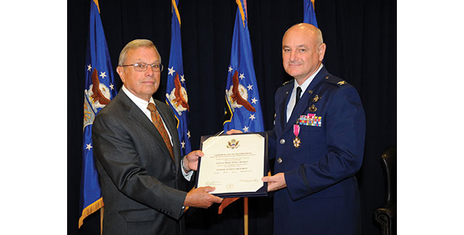
I had the honor of attending Colonel David Maddens’ retirement luncheon at the Space and Missile Systems Center (SMC) on Los Angeles Air Force Base (LAAFB) on June 16, and it was quite an event. Just prior to it, I asked Dave if he would like to conduct an exit interview after he took a short vacation with his family. He agreed it would be a good idea and a way to say some things he has wanted to say for awhile.
During the retirement luncheon, various people and organizations presented Dave with mementos of his time at the GPS Wing; I stopped counting at approximately 50 different presentations. This is an indication of the high regard in which Dave is held by those with whom he works on a daily basis. The military shadowbox he was presented (see photo), which is a typical military farewell presentation, had the following inscription, which is certainly not typical, and sums up the way those who work with Dave feel about him as a commander and as a person.
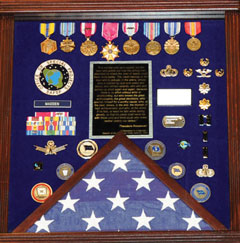
Theodore Roosevelt, 1910
“It is not the critic who counts: not the man who points out how the strong man stumbles or where the doer of deeds could have done better. The credit belongs to the man who is actually in the arena, whose face is marred by dust and sweat and blood, who strives valiantly, who errs and comes up short again and again, because there is no effort without error or shortcoming, but who knows the great enthusiasms, the great devotions, who spends himself for a worthy cause; who, at the best, knows, in the end, the triumph of high achievement, and who, at the worst, if he fails, at least he fails while daring greatly, so that his place shall never be with those cold and timid souls who knew neither victory nor defeat.”
Theodore Roosevelt
“Citizenship in a Republic,”
Speech at the Sorbonne, Paris, April 23, 1910
Dave was officially retired the next day by Colonel (USAF, retired) Bradford Parkinson. Dr. Parkinson was the first GPS Joint Program Office Director, in the early 1970s. He recently reviewed those early days and those responsible for the success of GPS with a two part series in the pages of GPS World.
Interview
Don Jewell (DJ): Dave, after almost four years first as the Vice Commander and then for the last three years the commander of the GPS Wing, of what are you most proud?
Colonel David Madden (DM): Overall, the GPS Wing has made significant progress over the years moving critical space system developments and acquisitions forward. The GPS Wing continues to lead with a “back-to-basics” foundation of rigorous system engineering, incorporated strategies like parallel risk reduction and capability insertion efforts, incremental delivery of timely and valuable capabilities to warfighters and civil users, and best business practices with solid cost estimates and contract incentives. Our new GPS III space vehicle, Next Generation Control Segment, and our GPS Modernized User Equipment programs incorporate our latest thinking of these innovations, and pave the path as a model for future acquisitions: low risk and high confidene associated with program execution (cost, schedule and technical performance).
The GPSW Team has had many specific accomplishments over the last four years. I would like to highlight just a few.
Space Segment. In the space segment, we accomplished a major milestone in GPS history with the launch of the final GPS IIR-M satellite in Aug 2009. GPS IIR-21 (M) marked a critical milestone in the GPS modernization program that was initiated in early 2000. The GPS IIR/IIR-M satellites are the cornerstone of the GPS constellation, and I expect them to perform well into the future. We’ve completed the development, testing and launch operations of the first GPS IIF Space Vehicle. The GPS IIF is the “Dawn of a New Era” of GPS services, providing new and improved capabilities that will continue to support not only the warfighter but commercial and civil users around the globe. IIF vehicles two and three will be delivered by early 2011, and two of the remaining nine fixed-priced vehicles are already proceeding down the Boeing Pulse Line.
Another noteworthy accomplishment was the award of the GPS III spacecraft contract. The GPS III will be developed in three increments with each increment to include more capabilities based on technical maturity. We successfully completed the GPS IIIA satellite Preliminary Design Review (PDR) in May 2009 and the GPS IIIA Critical Design Review (CDR) is scheduled for August 2010, two months ahead of schedule, which completes the detailed design and lays the foundation for fabrication. GPS IIIA is a back-to-basics spacecraft program with a strong focus on systems engineering, mission success, and acquisition excellence.
Ground Segment. In the GPS ground control segment, great lengths were taken to ensure the successful replacement of the decades-old command and control (C2) system with the new Architecture Evolution Plan (AEP) software, to improve GPS operator interfaces while providing a test capability for the new signals on the modernized satellites and to improve launch, anomaly, and disposal (LADO) operations. This new software will also provide robust security improvements to include “over-the-air” distribution (OTAD) of encryption keys to properly equipped military users.
I would also like to mention the successful award of the Next Generation Control Segment (OCX) back-to basics contract. The current acquisition strategy for fielding the OCX consists of four increments (commonly referred to as Blocks). The recently awarded OCX contract consists of Blocks one and two [while] Blocks three and four will be follow-on contracts that align with the future GPS IIIB and GPS IIIC spacecraft capabilities.

User Segment. In the GPS user equipment segment, we are actively working the development of a new generation of military user equipment to take advantage of the modernized M-Code [military only] signals. Currently we are conducting technical demonstrations and risk reduction for our next generation Military GPS User Equipment (MGUE) and defining a creative acquisition strategy.
USD-AT&L (the undersecretary of Defense for Acquisition, Technology and Logistics) signed an acquisition decision memorandum (ADM) on May 24, 2010, approving a material development decision for MGUE: the formal entry point for MGUE into the acquisition process. Currently, our three Military User Equipment (MUE) contractors are testing and delivering prototype cards this summer; government testing follows.
The foundation of our MGUE acquisition strategy is an incremental approach that leverages technology developed under the MUE program to move into engineering and manufacturing development of the first MGUE receivers as soon as possible. The strategy will be submitted to the Pentagon this summer after SMC coordination and PEO Space approval.
Our business strategy over the long term is to develop common GPS modules (CGMs) as the core engine for all DoD user equipment. We will develop CGMs incrementally as well, to support the form factors for the air, maritime, and ground domains. By early fall, we will have a final technical requirements document (TRD) for the MGUE form factors and CGM. We expect an RFP release in Feb 2011, and a Milestone A in May 2011. By early FY12, we should be on contract for Increment One of MGUE.
System Sustainment. From a systems sustainment standpoint, our GPS Wing detachment located at Peterson AFB has exceeded all expectation associated with ground (softwa
re and remote sites), user, and satellite systems sustainment. Even with all the system upgrades over the past year our sustainment team has kept the operational system performance well above the requirement: Read, no capability impact to civil or military users.
In fact, performance (availability, accuracy, and integrity) has been significantly improved over the last four years. Finally, they are normalizing sustainment of the current user equipment (DAGR-Defense Advanced GPS Receiver, MAGR-2K-Miniaturized Airborne GPS Receiver Version 2, and ADAP-Advanced Digital Antenna Production program) by transitioning sustainment responsibility to Air Force Material Command, specifically the Warner Robins Air Logistics Center depot at Robins AFB, Georgia.
Partnerships. The GPS Wing has established a close working relationship with Air Force Space Command Headquarters at Peterson AFB, Colorado for overall system operations, sustainment, and development responsibility; the 45th Space Wing (launch operations teams at Cape Canaveral Air Force Station in Florida), the 50th Space Wing (Overall System Operators at Schreiver AFB in Colorado), the Launch and Range Systems Wing (Los Angeles, California acquisition organization with responsibility for getting our GPS satellites successfully to orbit), the United Launch Alliance, the many government agencies (FAA, DOT, DOE, NSA, NGA, NASA, and so on), OSD organizations (PA&E, NII, AT&L, DOT&E), and our dedicated and professional prime contractors and major subcontractors to successfully sustain and enhance GPS mission capabilities — providing the highest overall daily system availability and the most robust GPS on-orbit constellation ever for war fighters and civil users worldwide. The constellation is healthier than it has ever been, and with the launch of the first IIF satellite and the on-track development of GPS IIIA, we are poised to maintain GPS as the gold standard for positioning, navigation, and timing well into the future.
The People. Finally and most importantly, I am proud of the men and women that make up the GPS Wing. They have molded many players (Aerospace, MITRE, service reps, international officers, government and civil agencies, SE&I and SETA (support) contractors, and U.S. Air Force military and civilians) into a finely tuned machine that is always focused on the number one priority: mission success. At the same time they have made the Wing a fun place to work. The GPS Wing members have made significant contributions to the quality of life in the GPSW, on LAAFB (Los Angeles Air Force Base), and the local community. Whether it was the great Company Grade Officer Association activities, tasty Tuesdays, the BBQs by the base gym, the holiday parties, the POW/MIA (Prisoner of War/Missing in Action) Run, the yearly toy contributions to the Marine Corp Toys for Tots program, regular food drives to support the Redondo Beach community, the yearly car show, the GPS Partnership Council, GPS University, or the many visits to local schools (just to name a few activities), they are truly a class act of which I was honored to be a small part.
DJ: Dave, how would you most like to be remembered?
DM: As the “AGER” guy. The one who put the enterprise back together, which will lead to better synchronization among the segments and ultimately deliver future warfighting capability to the U.S. and Allied forces. Senior AF, DoD, and Congressional leadership now look at GPSW execution as a enterprise rather than a collection of individual ACAT 1D (Acquisition Category 1D) programs. This has allowed the modernization program to move forward, significantly reducing the numbers of reviews, documents, and decision complexity.
DJ: Dave can you explain just where we are today in the ongoing GPS-IIF saga? Are we on track and on schedule to have IIF-1 activated sometime in late August? Will there be a second IIF launch this calendar year? Does Boeing finally have it all together?
DM: Don, I’m actually glad you asked the question that way, because it gives me an opportunity to address it squarely. It is completely fair to call the GPS IIF program a saga because of how long it took us to get to our first launch. But it is also important to ensure the credit and blame gets spread properly. The program did suffer from the sins of acquisition reform in the 1990s — on the government side and the industry side —- as well as major requirements changes years after program initiation. In hindsight, I’d have to say that we collectively failed again in the mid 2000s when we were overly optimistic about the time and funding needed for the challenges we would face in recovering from TSPR (Total System Performance Responsibility). On the flip side, during my tenure here I’ve had great support from my senior leadership — and from their Boeing counterparts — for taking the time necessary to ensure we have a quality program. We kept our eye on mission assurance and fixed quite a few end-of-life risks. We might not have had that luxury if the constellation weren’t so robust over the past few years.
In the end, the proof is in the on-orbit performance. So far, I’m proud to say that the checkout of SVN-62 has been proceeding very smoothly. My guys and Boeing have a great working relationship with the crews up at the 50th Space Wing, so the bird is in good hands. I expect we’ll find a few things we want to tweak before making the satellite available to users. Most space programs do that with the first satellite of a kind. In the end, the users will have a satellite that adds real benefit to the constellation performance.
Right now the teams are still pushing hard to get SV-2 ready to launch. There are still a few hurdles to clear, and the leadership needs to evaluate whether or not the constellation really needs another GPS IIF just yet or can it wait until next summer. I would love to watch another one go up this year, but it just won’t be the same watching from the sidelines!
DJ: I know it won’t be the same, Dave, but it should still be exciting. Now how about an update on the OCX program and how it is progressing?
DM: The OCX program is off to a great start. We awarded the contract to Raytheon in February 2010 and kicked off the integrated baseline review (IBR) in March. We are currently working side-by-side with Raytheon to solidify the program management baseline so we can jointly manage the program in a back-to-basics manner. Phase B software development for controlling modernized features is underway and builds on Phase A products, which we demonstrated with a prototype in December 2008. I have tremendous confidence that the OCX program will deliver promised capabilities on time to support modernized GPS.
DJ: Can you give us an update on where we are with the GPS IIIA program? Have you been successful in maintaining the no-changes mandate?
DM: GPS IIIA has maintained a stringent, back-to-basics approach since program inception. This has included significant investment in early systems engineering, and strict requirements discipline. To date, no new requirements have been levied on the GPS IIIA. Any new requirements for consideration are being addressed in future blocks as planned. The program is currently on track, and is forecasting the completion of Critical Design Review 60 days ahead of the baseline schedule.
DJ: We have satellites on orbit today that will reach their mean mission duration without broadcasting all resident signals or using all capabilities? Is there a plan to address this issue?
DM: Although there is some concern that the IIR-M satellites may reach their end of life before the L2C capability has been deployed, or that the IIF satellites may reach their end of life before L5 has gone operational, the concern is not justified by our reliability predictions and our current program plans. Current plans are for OCX Block 1 to provide L2C support, which is projected in the August 2015 timeframe, whereas the IIR-M satellites are expected to live well into the 2020 timeframe. Likewise, OCX Block 2 will provide L5 support in the 2016 timeframe, and our IIF satellites are expected to live into the 2025 timeframe. Therefore the likelihood that IIR-M or IIF satellites will be decommissioned before L2C or L5 have become operational, respectively, is very low.
Over the last couple of years, lots of discussion has gone into the integration issue, but I am not really sure what providing fully integrated GPS capability really means. What I do know is the user needs all three segments (satellite, ground command and control, and user equipment) to fully utilize new system capability. I also know that system integration comes in two forms. First and foremost from a technical design standpoint. This allows individual segments to be delivered independently but with high confidence the system will operate when all three elements arrive. This gives flexibility to the dynamics associated with budgets, policy decisions, requirements changes, unexpected technical hurdles, launch availability, and weapon platform availability for integration and testing (just to name a few variables). Rest assured the GPS enterprise is integrated at the technical level. However, it’s the second form of integration that gets all the attention: having all segments delivered in a reasonable proximity to each other. Not to make excuses, but as it relates to GPS, this is just hard to accomplish because it involves a span of control and accountability that is almost infinite. Many in the community recognize this reality, which has allowed the Air Force to set appropriate and realistic expectations so real capability can be delivered.
That being said, there are prudent things that can and are being done to speed the deployment of capability and set appropriate expectations. The most significant has been to broadcast the M-Code, L2C, and soon L5 signals from space to allow civil and military user equipment manufacturers to begin development and testing of their next generation of receivers. This gives industry a jump while the U.S. Air Force continues to develop the C2 capability and the next-generation signal monitoring capability (required to ensure signal in space performance integrity). Also, building the modernization programs with a strong mission assurance foundation is a major step forward. We understand the lessons learned that established the baseline for the current Block II systems delivery; the Block III systems are built on a solid acquisition strategy of reduced risk and increase execution confidence.
DJ: What do you see as one of the biggest GPS enterprise challenges, and what are some of your thoughts on the way ahead?
DM: That’s easy, Don: ensuring global PNT services are not interrupted as the United States continues to modernize GPS. If we don’t continue to develop a more robust means of ensuring user equipment compatibility, even a small number of non-system-compatible receivers (military or civilian) can significantly delay the delivery of critical modernized capability for everyone. Let me explain and provide some thoughts.
Since its initial design in the early 1970s, GPS has evolved in both capability and complexity. In the early days, systems engineering across the space, control, and user segments was relatively straightforward. The GPS Joint Program Office developed all military user equipment, and was able to rigorously ensure all specifications were verified prior to fielding. Over the past 20 years, however, GPS has become ubiquitous throughout the Department of Defense, with tailored satellite navigation solutions developed and acquired by dozens of program offices to support hundreds of unique requirements. Meanwhile, commercial GPS is one of the foundations of the Information Age, with GPS receivers produced in quantities approaching half a billion devices per year. The model of simply providing policies, standards, and interface control documents without providing a means to certify receiver compliance is becoming more challenging due to the continued growth in both military and civil applications for PNT, the competitive nature associated with user system applications and performance, and the increased complexity of GPS. Furthermore, it is especially difficult fielding upgrades to an established system like GPS while maintaining backwards compatibility with previously fielded equipment. These challenges are further exacerbated by difficulties associated with synchronizing the lengthy timelines associated with fielding ground-segment, satellite, and user equipment upgrades.
Recent highly isolated incidents, involving civilian and military receiver and other manufacturers, have highlighted the significant impact a very small number of receivers experiencing compatibility issues can have on the entire enterprise of worldwide users. In addition, a number of cases associated with improper receiver integration into major weapon systems have delayed system fielding as well not allowed the weapon system to best optimize GPS to the overall weapon systems performance.
Therefore, it is my opinion, to ensure worldwide PNT services are not interrupted as we continue to modernize the GPS, a more robust means of ensuring compatibility needs to be explored. (I would like to stop and make a note here: by “we” I mean all the DoD and civil agency stakeholders.) This means we need to not only continue to release “building codes” but we need to develop a capability to be more involved in the development, integration, and testing of new military and possibly civil user equipment.
We have recently taken a number of big steps in this direction.
First, we are currently significantly increasing the number of civil and military GPS receivers in our government testing labs. This will enable us to run tests against a wider variety of receivers, to gain higher confidence before we deploy system upgrades.
Second, we recognize that we need to ensure that our signal specifications, for both military and civil users, are as clear as we can make them. User-community representatives are already encouraged to be full participants in appropriate interface-control working groups. We further recognize that there is no substitute for thorough testing, and hence fully appreciate the importance of deploying signal-in-space capabilities as early as possible, on predictable schedules, so user equipment can be field-tested prior to market release or operational deployment.
Third, we are developing new upgrade fielding methodology whereby when we deploy system upgrades, we will take a more methodical approach and, whenever possible, field upgrades to smaller segments of receivers to prove compatibility without exposing all operational assets simultaneously. We will also apply a new software sustainment model to future military GPS user equipment, to ensure that inevitable system changes are systematically and rigorously executed with minimal impact on DOD programs.
Finally, we are investigating the establishment of something similar to an underwriters laboratory service to help support military programs with integrating GPS into their weapon systems during development. The teams associated with such lab services would support program design reviews as well as help develop the validation criteria for overall system acceptance. In addition, we are also starting discussions with key GPS civil receiver developers on how we might be able to provide a similar service to commercial receiver developers (potential fee-for-service type model).
Don, I highly recommend we continue to develop the four efforts I just mentioned but also dedicate significant time to critical thinking events to ensure we have minimized the risk of a widespread receiver issue, delays in delivering modernized capabilities, or sub-optimized weapon system performance. Manufacturers of equipment adversely affected by recent GPS upgrades have significantly stepped up their interactions with the GPS program office to resolve the compatibility issue and are playing a major role in providing an upgrade to their affected receivers to correct the issue. To date, no operational weapon systems have had to be grounded or civil capability degraded. I encourage the GPS community to treat recent events as a call to arms. GPS has become a critical national and international utility but it is much more complex than the electric or telephone services. How military or civil GPS receivers are designed, developed, and integrated into systems has a significant impact on the overall performance or lack of performance of the system. Don’t let recent events be a lesson not learned; let’s lead and solve the risk before it becomes an issue.
DJ: These are all excellent ideas, Dave, and many of them we have discussed in the past as concepts. It sounds like many of them are now a work in progress, but since you won’t be around to shepherd them into fruition, just what sort of prudent advice would you give Colonel Bernie Gruber as he assumes command of the GPS Wing?
DM: First and foremost, listen to your people — we have a great team! They are skilled professionals who really care about GPS. Second, keep the MGUE program focused and moving forward.
DJ: I certainly hope at a minimum that Bernie listens to your advice on MGUE. Now, Dave, when will the GPS Wing transition back to a Joint Program office, and what affect will this have on the military personnel working GPS? Will this re-designation be detrimental to their careers and future plans for the JPO? Will it lessen the GPS Wing’s/JPO’s influence in the GPS community and with other services?
DM: Don, we are scheduled to complete the transition and stand-up as the GPS Directorate on October 1, 2010. The Center is having one inactivation ceremony for all the Wings in SMC on September 8. The transition will be seamless and have a minimal effect on our military personnel. Our senior leadership is working on ensuring our materiel leader positions have group or squadron commander equivalency and will also be command-screened and boarded. There will not be very much difference within the Wing on a day-to-day basis. For the most part, the work, responsibility, and accountability will remain intact. The re-designation will have very little detriment upon the careers of the officers within the Wing. The officers’ records will show a transition and re-designation to explain the change, and that it is no cause of their own. As far as future plans for the organization, the strength of the leadership here in the Wing will still be in place and will be just as effective as it is now to lead each individual in our organization and to move forward and progress in GPS capabilities into the next era. Other services will still look to us to continue to forge advancements in GPS satellites so that our influence in the world’s GPS community will remain the standard: stronger than ever. Our organization will continue to acquire and sustain global navigation, positioning and timing services for our war fighters and civil users. We’ll still be the Green Monsters everyone knows and loves!
DJ: What message would you like to leave with our readers as you move on from GPS to the milsatcom community?
DM: GPS is in great hands. I look forward to the challenges ahead.
DJ: Any final comments, Dave?
DM: It has truly been a pleasure leading the GPS Team — my best job in 30 years of service. And you, Don, have also been a welcome friend.
GPS improves the quality of life for everyone on the planet. It saves lives both on the battlefield and in our cities and towns across the globe. The U.S Air Force and Air Force Space Command have been the diligent stewards of GPS since program inception in the 1970s and continue its commitment to this critical component of our national infrastructure. The current GPS constellation has the most satellites and the greatest capability ever. We are committed to maintaining our current level of service, as well as striving to improve service and capability through ongoing modernization efforts. The Air Force will continue to pursue an achievable path maintaining GPS as the premier provider of positioning, navigation and timing for military and civilian users around the world.
DJ: Dave, everyone at GPS World wishes you the best of luck in your future endeavors, and thank you for your honesty and candid responses to our inquiries through the years. You were the leader the GPS Wing needed for the last three plus years and you have left a legacy of which you can be justly proud. And in my opinion if the GPS Wing, Directorate or JPO thinks they have seen the last of Dave Madden, they should think again. Best of luck in milsatcom.


 The Elephant Charge (“Dust, Sweat, and Gears”), an annual off-road motorsport charity event, brings together competitors, their families, and supporters for a wilderness weekend of GPS-driven fun and frenzy in the Zambian bush. I’m for fun, but I always wince when I see folks tearing up habitat in the name of saving it.