Shuren Guo, deputy director of China Satellite Navigation Project Center.
By Shuren Guo
In line with its three-step development plan, the BeiDou Navigation Satellite System (BDS) will constitute a complete space constellation by around 2020, when it will be comprised of five geosynchronous orbit (GEO) satellites and 30 non-GEO satellites, providing services for global users. The year 2015 is of particular significance for the BDS establishment, which has witnessed stable operation of regional services and formal deployment of new-generation satellites. These satellites possess higher performance and better compatibility and interoperability with other navigation satellite systems.
In March 2015, the first new-generation BDS satellite, or 17th BDS satellite overall, was launched at the Xichang Satellite Launch Center, and kicked off the deployment of the BDS global constellation. Launched and directly inserted into an inclined geo-synchronous orbit (IGSO) by a Long March launch vehicle with a newly designed upper stage, the satellite is equipped with a new bus system, as well as a payload system carrying inter-satellite links and new navigation signals.
In July 2015, two mid-Earth orbit (MEO) BDS satellites, the 18th and 19th overall, were launched into their scheduled orbits precisely with one single launch vehicle. More new types of payloads are on board, and the satellite performance is dramatically improved. After the in-orbit-delivery, these two satellites are able to interconnect with other existing BDS satellites, and jointly carry out the experiment and verification of the global network deployment process.
In September 2015, another BDS satellite was successfully launched into IGSO, and became the 20th of the BDS space constellation. Different from pervious launches, this satellite reached its designed orbit by using its built-in autonomous orbit maneuver mechanism. For the first time, the satellite also carries a Chinese-made hydrogen atomic clock, which provides enhanced time and frequency reference capacities.
Currently, these last four launched satellites are in normal working mode. The ongoing in-orbit tests show that these satellites satisfy the desired requirements. At present, tests and validations for the new navigation signal system, inter-satellite links, and the new atomic clock are being conducted. Once the tests and validations are completed, these satellites will be included in the network, and start to provide services for global users.
In 2016, BDS will keep improving its service performance. Three BDS satellites will be launched to boost up the deployment of global constellation. The construction of the BDS augmentation systems will be accelerated. Meanwhile, international cooperation activities will be further promoted, and the application development process will be attached with much importance, to broaden the fields and domains of BDS/GNSS applications.
“To serve the world and benefit Mankind” is not only the purpose of BDS, but also its commitment to the world. On the basis of maintaining stable services, BDS will make all efforts to enhance the performance, to speed up the deployment of global constellation, and to provide better services for global users.
Shuren Guo is the deputy director of China Satellite Navigation Project Center. He received his bachelor’s degree in electromagnetic theory and microwave engineering from Xi’an Jiaotong University, and his master’s in electronics and communication engineering from Beihang University. As a researcher, he has long been engaged in the design, research and development of the BeiDou Navigation Satellite System.
We have grown accustomed to seeing market projections for some GNSS, notably Galileo. European GNSS Agency economists have done a remarkable job analyzing and predicting the global market over the past five years. Business intelligence firms in the U.S. periodically report on the power of GPS driving, or participating in, significant portions of the U.S. economy. Figures from Russia are scant but do occasionally emerge, even if they are difficult to integrate into a meaningful global picture.
Now the Global Navigation Satellite System and Location-based Services Association of China (GLAC) has issued a report asserting some lofty, often staggering, and occasionally surprising statistics and projections.
China’s satnav system is helping generate $31.3 billion for the country this year. That benefit is expected to double in five years.
70 percent of China’s population uses smartphones. That’s 980 million people who may be sending location requests at any given time. This constitutes the biggest growth sector found by the GLAC.
China’s installed base of navigation devices in private vehicles lags behind the United States, at less than 500,000, or 5 percent of cars, but 20 percent of 1 million commercial vehicles in China use products that access BeiDou technology.
“Sky’s the Limit for BeiDou’s Clients,” crowed China Daily. Meanwhile, halfway round the world in Prague, the Czech Republic, Jing Li of the China Transport Telecommunication & Information Center, reported to a conference of the International Association of Institutes of Navigation that a BeiDou global service will be provided by 2020. The National Differential BeiDou Ground-Based Augmentation System will have 175 reference stations, with more than 1,000 network stations and a space-based augmentation system to boot. So far, the system has hit every benchmark.
Some market projection figures strike one as wildly optimistic, while others have proved true. Some GNSS appear to grow or modernize in fits and starts. But BeiDou appears steadily ascendant.
China’s new third-generation BeiDou satellites are broadcasting some new signals in space. The newest signal, which just began broadcasting from a satellite launched on Sept. 30, is similar to the future GPS L1C signal with time-division BOC(1,1) and BOC(6,1) signals. Such a type of modulation is called time-multiplexed binary offset carrier (TMBOC).
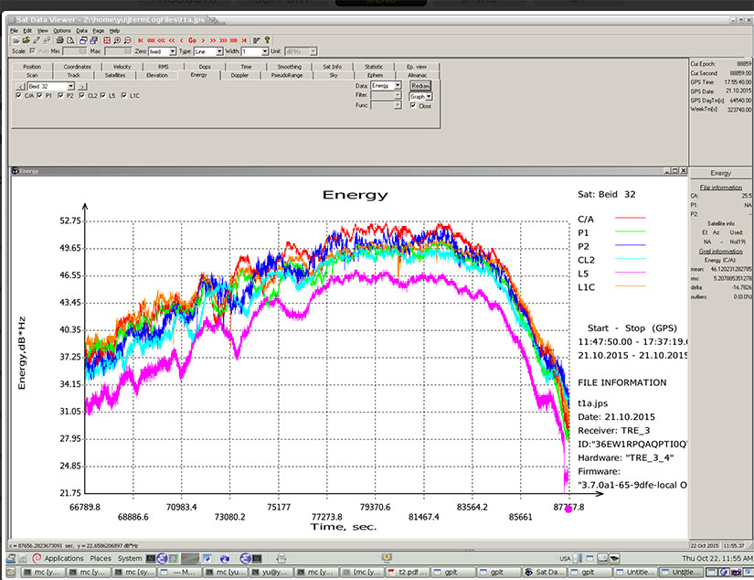
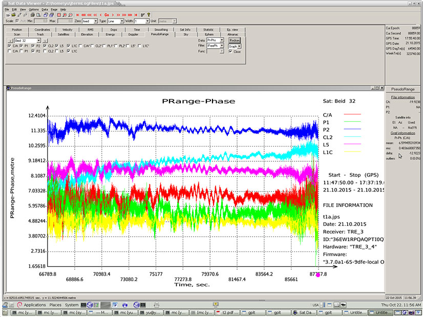
Researchers at JAVAD GNSS have been tracking the new signals, particularly those from BeiDou-3 I2S, an inclined geosynchronous orbit (IGSO) spacecraft, NORAD number 40938. I2S is transmitting on three frequency bands.
The JAVAD researchers used the decoding approach described in their February 2013 GPS World article, “Signal Decoding with Conventional Receiver and Antenna: A Case History Using the New Galileo E6-B/C Signal” by Sergei Yudanov. As a result, the signal’s structure was decoded and L1C TMBOC tracking has been successfully tested on the JAVAD GNSS TRE-3 receiver.
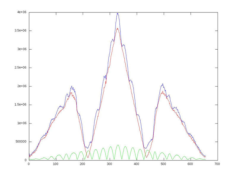
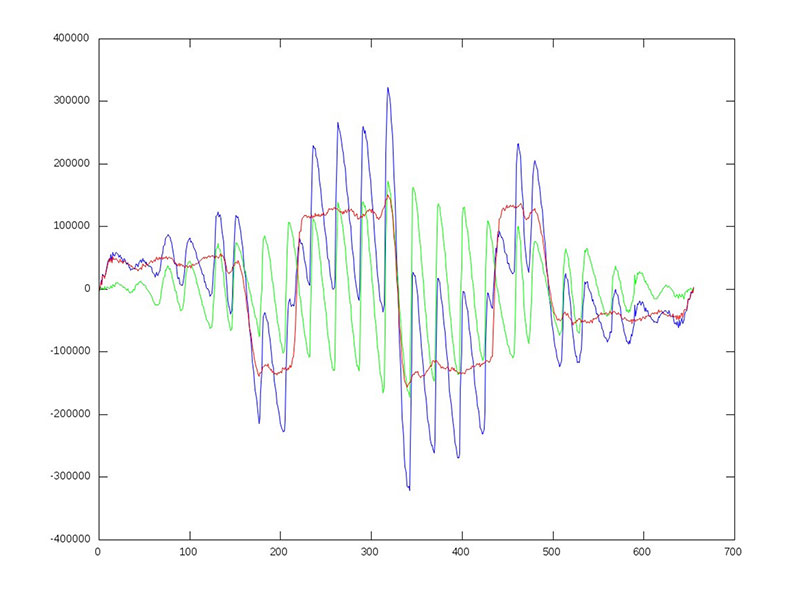
In addition, new signals on 1575.42+1.023*14 MHz (B1-2), 1176.45 MHz (E5A) and 1207.14 (E5B) frequencies for three satellites (PRN 32, 33, 34) also have been decoded and tested. Figures 1–4 illustrate the experiment.
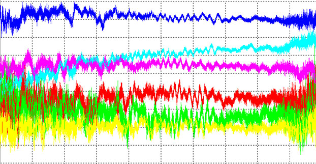
Figure 1: BeiDou TMBOC: correlation intensity (l) of BOC(1,1) (red), BOC(6,1) (green) and their sum (blue) versus code chips.Figure 2: BeiDou TMBOC: Output of “early-late” correlator (dI or derivative of I) of BOC(1,1) (red), BOC(6,1) (green) and their sum (blue) versus code chips.Figure 3: BeiDou TMBOC Signal: Horizontal axis: 0 – minus one chip shift; 327 – zero shift; 655 – plus one chip shift. C/NO and iono-free “range minus phase.” Slot – BeiDou signal: C/A – B1; P1 – B1-2; P2 – E5B; L2C – B3; L5 – E5A; L1C – L1C.Figure 4 (right): BeiDou TMBOC Signal: Horizontal axis: 0 – minus one chip shift; 327 – zero shift; 655 – plus one chip shift. C/NO and iono-free “range minus phase.” Slot – BeiDou signal: C/A – B1; P1 – B1-2; P2 – E5B; L2C – B3; L5 – E5A; L1C – L1C.
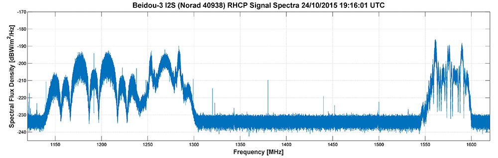
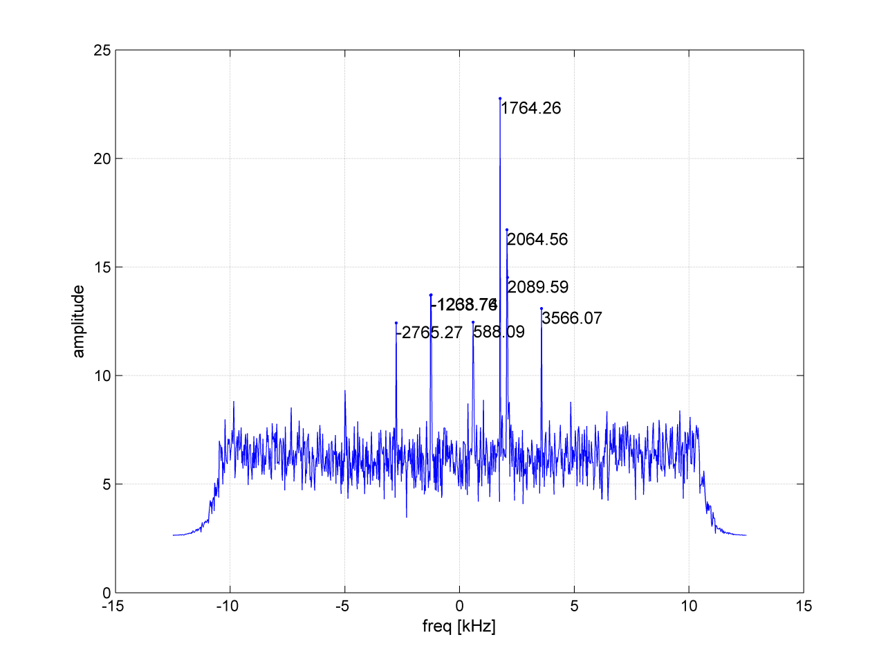
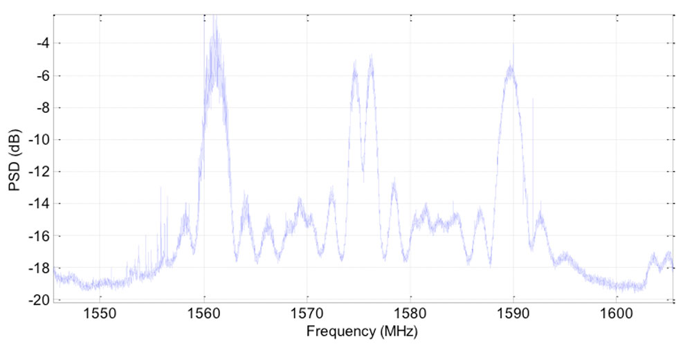
Researchers Steffen Thoelert and Michael Meurer from the Deutsches Zentrum für Luf t- und Raumfahrt (DLR, German Aerospace Center) have also been busy tracking the newest BeiDou IGSO satellite. Figure 5 shows a spectral measurement of the complete GNSS L-band frequency range, which shows the signal transmissions on B1, B2 and B3 band. The signal was captured with DLR’s high-gain antenna in Weilheim, operated by the DLR German Space Operations Center in Oberpfaffenhofen.
Figure 5: BeiDou Signal: Complete GNSS L-band frequency range, which shows the signal transmissions on B1, B2 and B3 band.
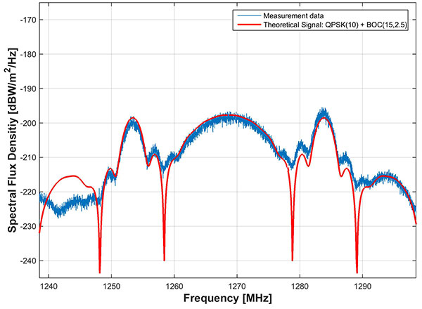
In comparison to the two latest BeiDou-3 MEO satellites, launched on July 25, the IGSO has an additional signal on the B3 band. The MEO satellites transmit only the QPSK(10) whilethe new IGSO also transmits an additional BOC(15,2.5) signal. Figure 6 shows the B3 frequency band separately including a combined theoretical signal (QPSK(10)+BOC(15,2.5)).
Figure 6: BeiDou Signal: the B3 frequency band separately include a combined theoretical signal PSK(10)+BOC(15,2.5)).
IIF-11 up: penultimate GPS Block IIF satellite
A United Launch Alliance Atlas V 401 launched the GPS IIF-11 mission for the U.S. Air Force on Oct. 31.
GPS IIF-11 is the second to last of the Block IIF satellites, delivering a second civil signal (L2C) for dual-frequency equipment, and a new third civil signal (L5) to support commercial aviation and safety-of-life applications. The next generation of GPS satellites is GPS III.
GPS IIF-11 is the third GPS mission to rise this year. GPS IIF-9 launched in March, and GPS IIF-10 in July. The next satellite, GPS-IIF-12, the last of its generation, is destined for space in early February 2016.
Galileos chirp
Shortly after the Galileo satellite using the E24 PRN code started transmitting on Oct. 10, its sibling began transmitting using code E30. Several stations participating in the International GNSS Service Multi-GNSS Experiment are tracking the new satellites; first among those reporting was the University of Liege, Belgium, using its Septentrio PolaRx4 and PolaRxS receivers to download signals.
The two satellites were launched on Sept. 11. A team of engineers from ESA and France’s CNES space agency are preparing for the next launch, scheduled for December.
In addition, new signals on 1575.42+1.023*14 MHz (B1-2), 1176.45 MHz (E5A) and 1207.14 (E5B) frequencies for three satellites (PRN 32, 33, 34) also have been decoded and tested.
Here are graphs illustrating the experiment:
I of BOC(1,1) (red), BOC(6,1) (green) and their sum (blue) vs code shift.
dI of BOC(1,1) (red), BOC(6,1) (green) and their sum (blue) vs code shift.
Horizontal axis: 0 – minus one chip shift; 327 – zero shift; 655 – plus one chip shift
Shortly after the Galileo satellite using the E24 PRN code started transmitting, its sibling began transmitting using code E30. Several stations participating in the International GNSS Service Multi-GNSS Experiment are tracking the new satellites.
Prof. René Warnant from the University of Liege has reported that as of 10 October, their PolaRx4 and PolaRxS receivers (but not yet NetR9 receivers) are tracking one of the new Galileo satellites using code E24.
Meanwhile, the latest BeiDou satellite, BeiDou I2-S, appears to have reached its orbital slot with a nominal nodal longitude of 95 degrees east.
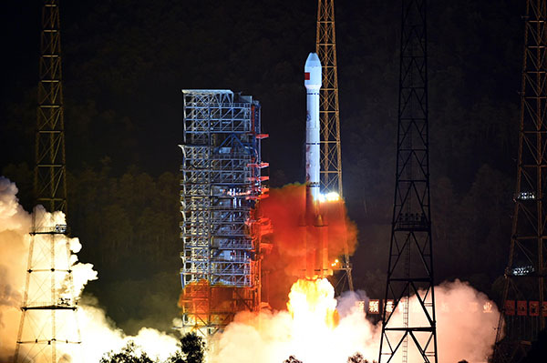
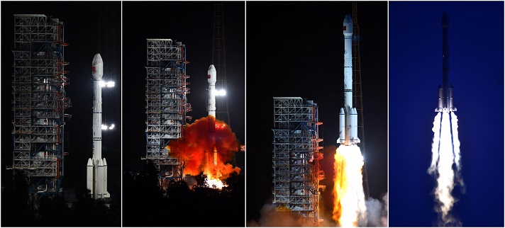
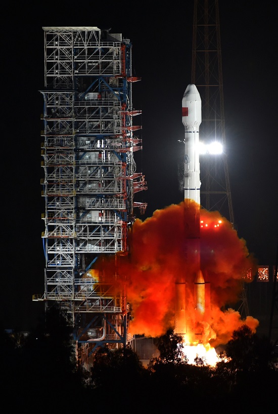
The 20th BeiDou satellite is launched, Sept. 30, 2015.
China launched a new-generation BeiDou satellite into orbit at 7:13 a.m. China Standard Time on Wednesday, Sept. 30, according to the Xinhua News Agency, the 20th satellite for the BeiDou Navigation Satellite System.
The satellite was launched from Xichang Satellite Launch Center in the southwestern province of Sichuan aboard a Long March-3B carrier rocket.
In a first for BeiDou, the new BeiDou satellite is equipped with a hydrogen maser atomic clock. A series of tests related to the clock and a new navigation-signal system will be undertaken, according to the center as reported by Xinhua.
China plans to expand the BeiDou services to most of the countries covered in its “Belt and Road” initiative by 2018, and offer global coverage by 2020.
Named after the Chinese term for the plough or the Big Dipper constellation, the BeiDou project was formally launched in 1994. The first BeiDou satellite was launched in 2000.
Two videos of the launch are available on the CCTV website.
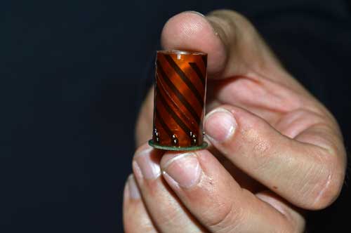
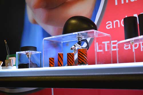
Andy Yin, international sales director at ComNav Technology Ltd., talks about the company’s M300 Pro and new OEM boards at INTERGEO 2015, which was held Sept. 15-17 in Stuttgart, Germany.
The M300 Pro GNSS reference station receiver integrates ComNav’s new-generation OEM board and includes web service and remote control features.
The first OEM board, which can support all GNSS constellations (GPS, GLONASS, BeiDou and Galileo), will be released at the end of September, according to ComNav.
Exhibiting at CTIA Super Mobility 2015, Vanja Maric, director of sales and marketing for Rockville, Maryland-based antenna-maker Maxtena, pointed out the challenge that exists for antenna makers in an uncertain drone market: forecasting what will happen next and planning for that future.
“The problem with the drone space its so volatile and so fragmented, and it’s very, very hard to predict,” Maric said. “Speaking to industry leaders in the UAV market, they don’t even know what it’s going to be in three years, and it’s very hard to put all your cards in that.”
That fragmentation is largely a dichotomy between the needs of the professional-grade market and the recreational drone pilots, Maric said. Maxtena is currently the antenna provider for several large UAV manufacturers, although confidentiality prevents them from being named.
“It all comes down to the necessity of precision, and different industries have different needs. UAVs, for example, some use very simple GPS patch antennas, simple receivers and precise location is not as important,” he said. “Then you have guys in the professional space where it is a necessity.”
That necessity right now is in the survey market, particularly RTK solutions for construction and mining operations in emerging countries. The company has seen an uptick in customers from Asia looking for antennas for Beidou. More specifically, Maric said handhelds for lone worker tracking in open pit mining in China has had “fantastic” growth. The M1227 antenna released earlier this year accomplishes this goal.
Maxtena GPS antennas at CTIA 2015
“It’s not just hardware; they have a lot of costs—software, mapping— in on all that, and if that package is right, you have something special. However, don’t forget: The antenna is the link between you and the satellite. That antenna has to be right; that’s what most companies forget,” Maric said. “You can have the best receivers and software in the world, but if you can’t make the link you can’t do it.”
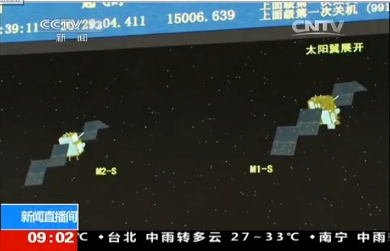
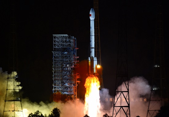
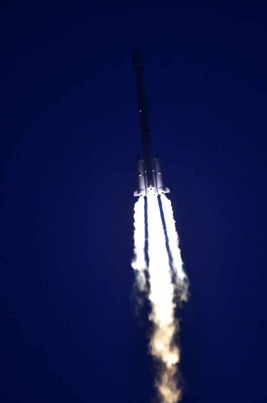
China launched two BeiDou navigation satellites into medium Earth orbit on July 25.
China launched two BeiDou navigation satellites into medium Earth orbit on July 25.
The two new satellites, BeiDou-3 M1 and BeiDou-3 M2, are in orbital slots 1 and 6 of Plane 1 (or A Plane), respectively. The satellites are designated BDS M1-S and M2-S — the “S” may stand for “Test” (in Chinese: 试验 = Shiyan).
On Aug. 14, China stated one satellite was working autonomously and had set up a link with the other satellite, successfully testing the autonomous control technology of the Beidou constellation. The inter-satellite link realizes communication and distance measurement among satellites, bringing autonomous control of the system a step closer.
Autonomous navigation is the project’s key to global operation. It enables satellites to work independently, providing users with more accurate data, according to BeiDou design engineers.
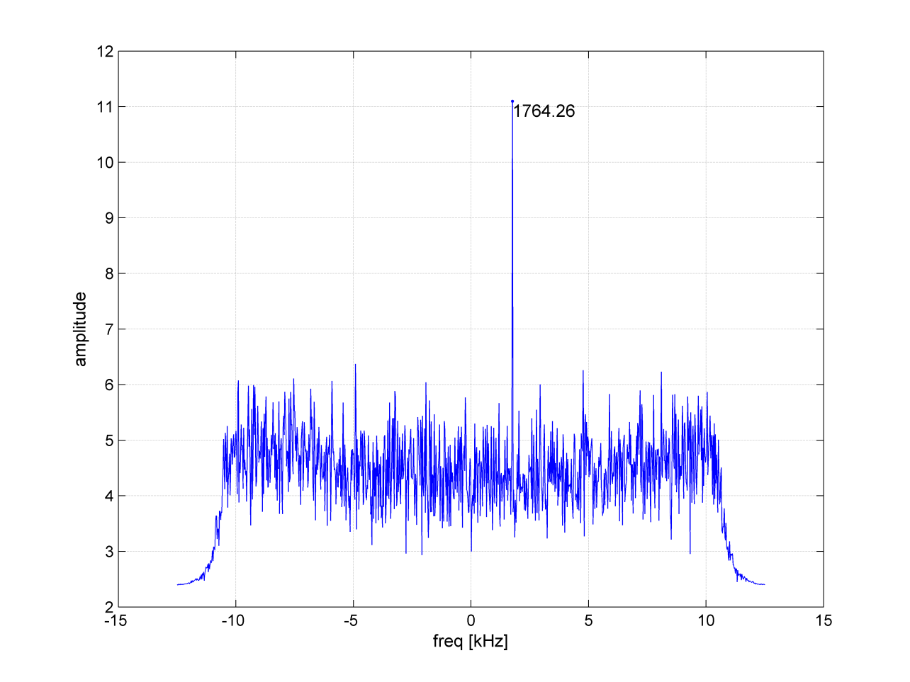
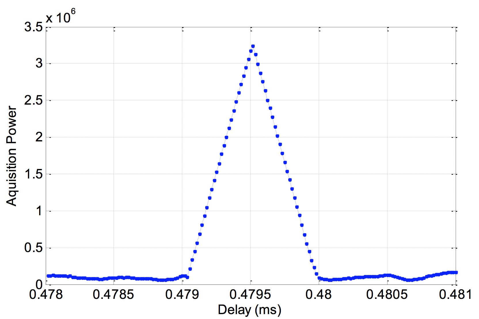
On Aug. 9, signals from the two new BeidDou satellites were received with a software-defined radio sampler operated at the European Commission’s Joint Research Centre in Ispra, Italy. The sampler is driven by orbit-prediction software that triggers a synchronized acquisition on both 1575.42 MHz and 1278.75 MHz using 1-bit complex samples at 60 megasamples per second (about 60 MHz total bandwidth). The two-line element sets for the orbits were obtained from the CelesTrak website, and predicted positions were computed using code developed following the Simplified General Perturbations Satellite Orbit Model 4 (SGP4) as documented in the U.S. Department of Defense Spacetrack Report No. 3.
To confirm the identity of the satellite being tracked using codeless tracking, we matched the measured Doppler frequency shift with the predicted one. The local oscillator clock drift was modeled using GPS L1 C/A-code signals and taken into account when matching the Doppler shift.
According to a presentation given at Stanford University’s 2014 PNT Symposium by Mingquan Lu and Zheng Yao from Tsinghua University, modernized BeiDou satellites broadcast an MBOC(6,1,1/11) [a multiplexing of BOC(6,1) and BOC(1,1) signals] and a BOC(14,2) signal on the L1 frequency. Neglecting the BOC(6,1) term, side lobes were brought to baseband and cross-correlated by our equipment. In Figure 1, the peak at 1756.41 MHz is BEIDOU-3 M2. This is also confirmed by cross-correlating the lobes of the BOC(14,2) signal, which is quite a unique feature of the new satellites (see Figure 2).
On Aug. 10, a 1.8-meter dish was pointed at the satellite, and a Tektronix RSA306 USB Real Time Spectrum Analyzer was used to sample the signal on L1 with 14-bit resolution at 112 megasamples per second. The resulting power spectrum is shown in Figure 3.
Figure 3. Power spectral density of BEIDOU-3 M2 on L1.
The spectrum shows very good overlap between the anticipated BOC(1,1) signal in red, BOC(14,2) in green and BPSK(2) in black. In fact, PRN33 correlates with the low side lobe suggesting that the satellite is also broadcasting a legacy signal on 1561.098 MHz (see Figure 4).
Figure 4. Cross-correlation of a BPSK(2) BeiDou code PRN33 on a 1561.098-MHz carrier.
Meanwhile, tracking by stations participating in the International GNSS Service Multi-GNSS Experiment has established that the second recently launched BeiDou Phase 3 MEO satellite is using PRN code 34, and that the first Phase 3 satellite, BeiDou I1-S launched on March 30, 2015, into an inclined geosynchronous orbit, is using PRN code 31.
Editor’s Note: The article below has been greatly revised and expanded from the original version published Aug. 10.
By Michele Bavaro, James Curran and Joaquim Fortuny
On July 25, 2015, China launched two modernized BeiDou satellites. Although the nomenclature is still uncertain, the Joint Space Operations Centre / North American Aerospace Defense Command identifiers for the satellites are BEIDOU-3 M1 and BEIDOU-3 M2. The satellites have been placed in medium Earth orbit (MEO) and both satellites have reached their designated orbital slots.
On Aug. 9, some signals from these satellites were received with a software-defined radio sampler operated at the European Commission’s Joint Research Centre in Ispra, Italy. The sampler was driven by orbit-prediction software that triggers a synchronized acquisition on both 1575.42 MHz and 1278.75 MHz using 1-bit complex samples at 60 megasamples per second (about 60 MHz total bandwidth). The two-line element sets for the orbits were obtained from the CelesTrak website and predicted positions were computed using code developed following the Simplified General Perturbations Satellite Orbit Model 4 (SGP4) as documented in the U.S. Department of Defense Spacetrack Report No.3.
To confirm the identity of the satellite being tracked using codeless-tracking, the measured Doppler frequency shift measured by the codeless-tracking receiver was compared with the Doppler predicted using the SGP4. The local oscillator clock drift was modeled using GPS L1 C/A-code signals and taken into account when matching the Doppler shift.
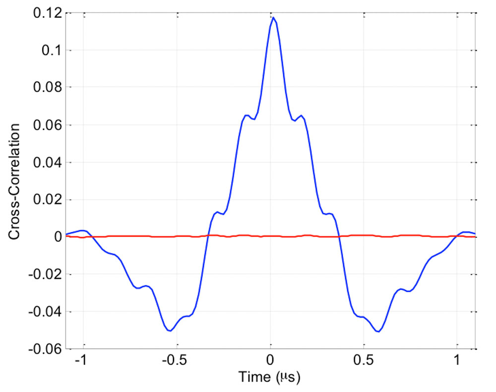
According to a presentation given at Stanford University’s 2014 PNT Symposium by Mingquan Lu and Zheng Yao from Tsinghua University, modernized BeiDou satellites are expected to broadcast an MBOC(6,1,1/11) signal, being a multiplexing of BOC(6,1) and BOC(1,1) signals, and a BOC(14,2) signal on the L1 frequency. Neglecting the BOC(6,1) component, the two BPSK(1) lobes of the BOC signal were brought to baseband and cross-correlated by our equipment, in an effort to detect the presence of the broadcast signals. In Figure 1, the peak at 1756.41 kHz is believed to correspond to the MBOC(6,1,1/11) signal broadcast by the BEIDOU-3 M2 satellite.
Figure 1. BOC(1,1) cross-correlation.Figure 2: Power spectral density of BeiDou-3 M2 on L1. Signal collected using a 1.8m steerable dish.
On Aug. 10, a 1.8-meter dish was pointed at the satellite and a number of further datasets were collected. The power spectrum estimated from one of these datasets is shown in Figure 2. Upon first inspection, the spectrum shows very good agreement with the anticipated MBOC(6,1,1/11) signal, centred at 1575.42 MHz. Further testing revealed that the BeiDou pseudorandom noise code (PRN33) correlates with the low side lobe, indicating that the satellite is broadcasting a legacy B1I signal on 1561.098 MHz. A replica of the B1I PRN code was generated and correlated against the received signal, to confirm the presence of the legacy BPSK(2) signal. A trace of the cross-correlation function is shown in Figure 3.
Figure 3. Cross-correlation of a BPSK(2) BeiDou code PRN33 on a 1561.098-MHz carrier.
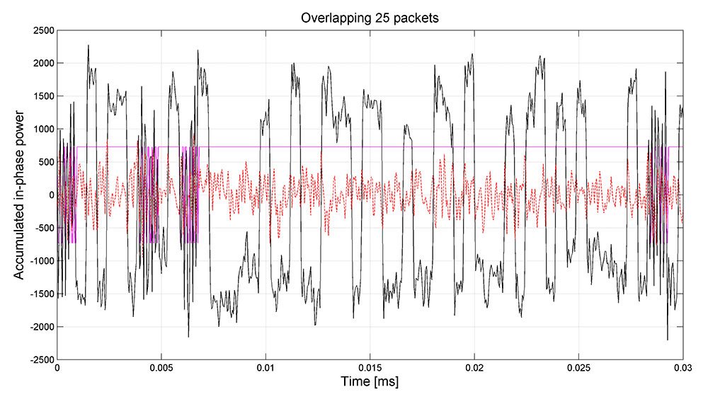
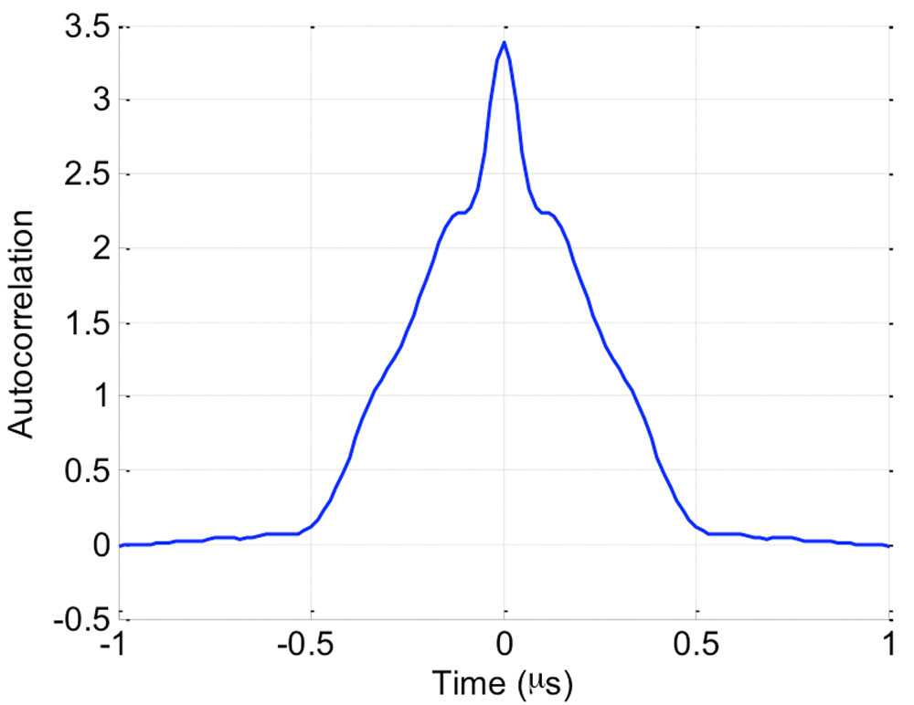
Further examining the IF data, we were able to determine the exact modulation of the central MBOC -ike signal. The raw IQ samples corresponding to the center of the L1 band were filtered to approximately 10 MHz, keeping only the MBOC signal, and tracked using a phase-locked loop operating directly at the 60 MHz sample rate, to recover the phase of the signal, prior to correlation. These phase-coherent samples were examined to gain some insight into the modulation. A simple autocorrelation of these phase-coherent samples suggested that there was no power in the quadrature channel, but that the in-phase channel contained what appeared to be an MBOC signal. More interestingly was the observation that the autocorrelation was periodic with a period of 10 milliseconds, suggesting the presence of a 10,230-chip primary code. An example of the autocorrelation of these phase-coherent samples is shown in Figure 4.
Figure 4: Autocorrelation of the TMBOC(6,1,4/33) pilot signal centred at 1575.42 MHz.
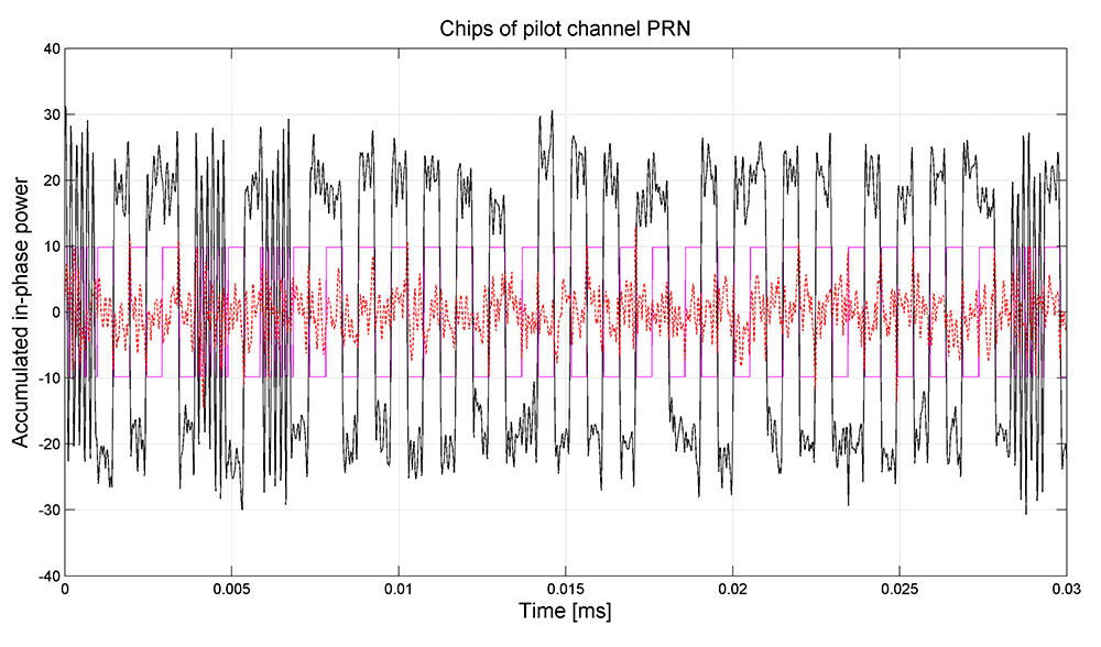
As the signal appeared to have a repetition period of 10 milliseconds, it was possible to perform a coherent combination of many successive 10-millisecond periods to achieve a sufficiently high signal-to-noise ratio to examine the modulation in detail. This process revealed what appears to be a TMBOC(6,1,4/33) modulation. Interestingly, once we aligned the samples to a 20-millisecond system time boundary via tracking of the legacy signal, the allocation of the BOC(6,1) component and the BOC(1,1) component could be identified. This pattern appears to be identical to that of L1C signal, being four segments of one-chip duration in each successive group of 33 chips. Specifically, chips {1,5,7 and 30} are allocated a BOC(6,1) pulse, and the remainder of the 33 chips are allocated BOC(1,1) pulses, as shown in Figure 5. Having produced a replica for the BOC(1,1) and BOC(6,1) components, we were able to implement a matched filter to extract the spreading sequences.
Figure 5: TMBOC(6,1,4/33) modulation visible on the received signal. In magenta, the expected chip allocation of the time-division MBOC.
Further analysis revealed that the pilot signal was modulated by an overlay sequence, having a repetition period of 18 seconds, again, similar to that of the L1C specification. Leveraging the alignment to the 6 seconds boundary of the legacy signal, the overlay code, having a length of 1800 symbols, was extracted. The code has been circularly rotated to match with the 18-second boundary of the legacy SOW (Seconds Of Week). Note, however, that while the relative values of the primary and secondary code are likely correct, there still exists a single uncertainty as to the overall sign of the two codes. The correct codes may indeed be the inverse of what was extracted.
The assumption that a power sharing favoring the pilot over the data as suggested by Lu and Yao was confirmed by the fact that the demodulated chips do not obviously appear as a three-level signal (as one would expect, for example, with Galileo E1B-E1C). Rather, the amplitude of the received signal was dominated by the pilot signal.
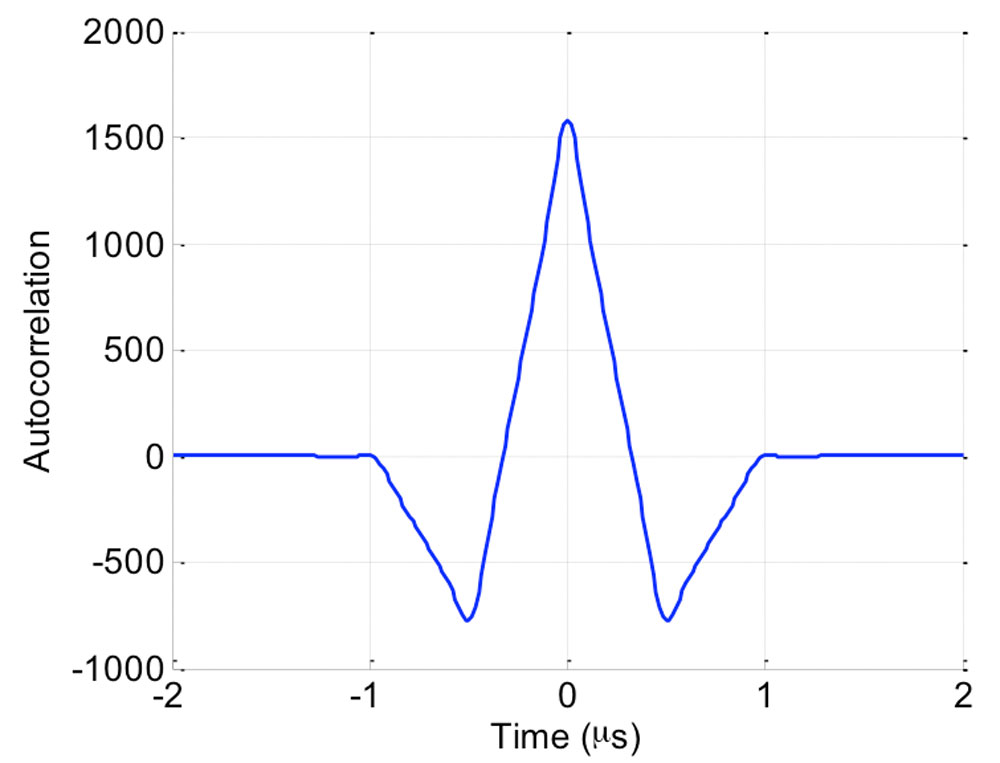
Figure 6: Autocorrelation of the BOC(1,1) data signal centred at 1575.42 MHz.Figure 7: Coherent accumulation of modernised BeiDou OS data channel (pilot stripped with SIC) over 0.5 seconds. In magenta the expected subcarrier pattern is shown.
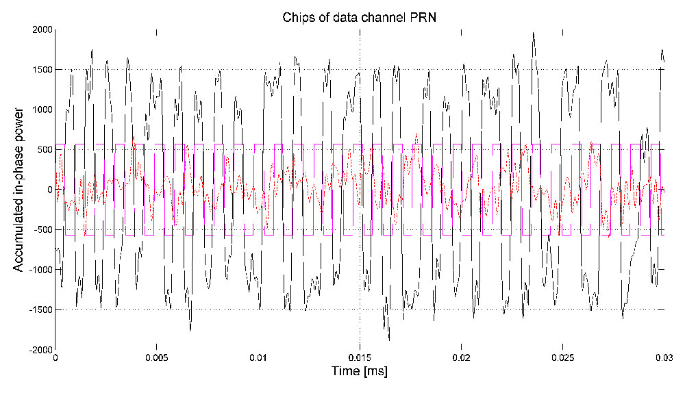
Having extracted the pilot code, we could perform successive interference cancellation (SIC) and strip its power contribution from the signal. An attenuation of 10 dB was sufficient to bring the spreading code of the data channel to the surface, which was readily achieved, even when using low-resolution samples. After we extracted the phase of the pilot signal, the samples were aligned to be phase coherent and the autocorrelation was examined. This appeared as a BOC(1,1) signal with a period of 10 milliseconds and aligned in phase with the pilot signal. The autocorrelation is shown in Figure 6. Using again the technique described above, the individual chips were examined, as shown in Figure 7, where it is clear that the TMBOC modulation is used only on the pilot signal, and that the data signals is, indeed, a simple BOC signal. Again, a PRN sequence of length 10,230 chips was extracted.
Knowing the PRN code for the data it was also possible to demodulate the navigation symbols, which do not show any particular repetition period, suggesting a weak or no preamble, similar to the approach taken by the GPS L1C design. Given both PRN code sequences, it was possible to track the signals and estimate the actual power-sharing ratio. Initial measurements suggest that there is a ratio of 2:1 favouring the TMBOC pilot signal.
A further effort was made to identify the modulation of the two lobes, spaced at ±14 MHz relative to the center frequency. Suggestions in the literature, had indicated that these were upper and lower lobes of a BOC(14,2) signal. Initial study, however, indicates that this may not be the entire picture.
Firstly, the upper lobe, centred at 1589.742 MHz, was examined. Placing a tight filter around the main lobe and examining the chips showed a number of interesting features. Firstly, it appears to be a simple BPSK(2) signal, having a 20,460 chip code, with a 10-millisecond repetition period. It also seems to be modulated by a secondary code. The secondary code is of 20-millisecond duration, with each symbol having a duration of 1 millisecond. Interestingly, this code was found to be the same Newman-Hoffman code used on the legacy B1I signal at 1561.098 MHz, and is given by:
00000100110101001110.
A peculiar feature of this signal is the appearance of a data modulation, having a symbol period of 10 milliseconds. In all, it appeared as though the signal has a primary code with a chip-rate of 2.046 megachips per second and a period of 10 milliseconds; a secondary code with a symbol period of 1 milliseconds, repeating every 20 milliseconds, and a further data modulation with a symbol period of 10 milliseconds.
When examining the received chips more closely, a number of gaps in the signal power were observed, corresponding to the same pattern as was observed on the pilot signal at L1. This suggested that it might also be a time-division signal, but that the narrow filtering that had been applied had rejected the second component.
Figure 8: Coherent accumulation of the time-division BPSK(2) and BOC(6,2) signal located at L1 + 14 MHz over 0.5 seconds. In magenta the expected time-division pattern between chips of the BPSK and the BOC components is shown.
To identify if there was another signal broadcast during these outages, we made a search for any signal in the vicinity that followed the same modulation of secondary and data symbols as the main BPSK(2) lobe. A BOC(6,2) component was found, with lobes spaced at 6 MHz on either side of the main BPSK lobe. Specifically, they were located at 1583.604 MHz and at 1595.88 MHz, representing a BOC(6,2) component for the BPSK(2) signal at 1589.742 MHz. Once this second signal component was identified, the received samples were re-processed with a wider bandwidth, such that the entire signal could be examined. A trace of the chips is presented in Figure 8.
Indeed, this seemed a very unique signal: being centred at 1589.742 MHz, being a time-division of a BPSK(2) signal and a BOC(6,2) signal, with a time-sharing of 8/66 and a pattern given by: {1, 2, 9, 10, 13, 14, 59, 60}. Having identified the signal period as 20 milliseconds, including the secondary code, we phase-aligned the received samples and measured their autocorrelation, as shown in Figure 9.
Figure 9: Autocorrelation of the time-division BPSK(2) and BOC(6,2) signal centred at 1589.742 MHz.
Although the work had identified three signals: the TMBOC pilot signal at L1; the BOC data signal at L1; the time-division BPSK and BOC signal at L1+14 MHz, and had confirmed the presence of the legacy B1I signal at L1-14 MHz, the question of the presence of the reported BOC(14,2) signal at L1 remained. Early experiments, showing the characteristic BPSK(2) cross-correlation between the signals at ±14 MHz had suggested its presence. A lack of periodicity in this cross-correlation had further suggested that it may have a non-repeating spreading sequence. However, as yet, no conclusive evidence of its presence has been found.
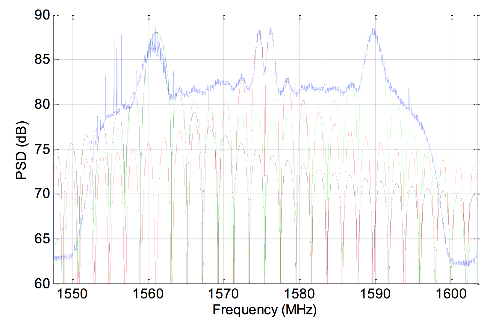
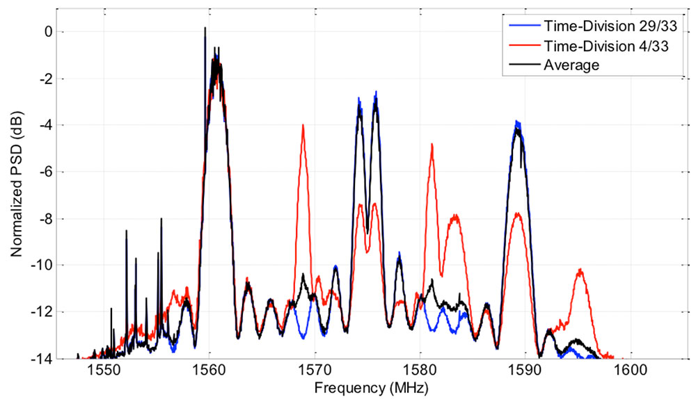
To further investigate the presence of the BOC(14,2) signal, the spectrum of the received signal was again examined. As it had been identified that there was a time-division modulation on both the TMBOC signal at L1, and on the BPSK(2)-BOC(6,2) signal L1 + 14 MHz, which used the same time-division pattern, a spectrum of the two different portions of time was estimated. The instantaneous power broadcast during each of these two periods is shown in Figure 10. This instantaneous power spectral density (PSD) represents the power broadcast at any instant by the satellite, and will be either one or other of the PSD shown, dictated by the time-division pattern (periods 1, 5, 7 and 30 out of every 33 periods). The average power of each spectrum will be, of course, scaled by 4/33 and 29/33, respectively. Note also that the relative power is distorted across frequency by the gain of the antenna element. In particular, the higher frequencies, above 1600 MHz, are attenuated by approximately 3 dB or more.
This confirmed a number of previous observations. Firstly, it was confirmed that the L1 signal contained a TMBOC signal, and a BOC signal having half of the power, as indicated by the 29/33 curve having twice the power of that of the 4/33 curve in the two BOC lobes at L1. Secondly, it confirmed the presence of the BOC(6,1) at L1 and of the BOC(6,2) at L1 + 14 MHz. Finally, it was noted that the two BPSK(2) lobes, at ±14 MHz both contain a non-time-division component. In the case of the -14 MHz lobe, there is no time division, as the power is constant for both the 4/33 and 29/33 periods. In the case of the 14 MHz lobe, it is clear that half of the power is time-multiplexed, as there is a 3 dB difference between the 29/33 and 4/33 periods. This indicates that there is a continuous BPSK(2) signal broadcast at +14 MHz. What is more, comparing the spectrum to that of the line-spectrum observed on the -14 MHz lobe, it is likely modulated with a very long, or non-repeating, spreading sequence. One explanation for this is the presence of a BOC(14,2) signal having a non-periodic spreading sequence.
Figure 10: The normalized Time-Division PSD measurement of the received signal, illustrating the instantaneous power broadcast during the 29/33 portion and the 4/33 portions.
An identical analysis of the second satellite, BEIDOU-3 M1, was conducted to determine whether or not the signal specifications of both satellites were similar. Indeed, they were found to be identical, again having a TMBOC and BOC data-pilot pair centered at L1, a Time-Division BPSK-BOC signal centered at L1+14 MHz and a legacy B1I signal at L1-14 MHz. Once again, there also appears to be a BOC(14,2) transmitting a non-repeating spreading sequence.
It appears, therefore, that the new BeiDou signal baseline will consist of a TMBOC civil signal at L1, containing a data TMBOC(6,1,4/33) pilot signal and a BOC(1,1) data signal very similar to that of the GPS L1C. This signal is complimented with a pair of open signals: one being the legacy B1I signal, located at L1 minus 14 MHz; and the second being a Time-Division of a BPSK(2) and a BOC(6,1). Beneath these two signals there also appears to be a BOC(14,2) signal having a non-repeating spreading sequence. This signal scheme is consistent between the two new satellites, BEIDOU-3 M1 and M2.
The authors invite any interested parties to contact them for more information.
The two BeiDou satellites launched July 25 are now operating autonomously, according to the news site English.news.cn. The satellites were launched by a Long March III-B rocket from the Xichang Satellite Launch Center in Sichuan Province, southwest China. The twin satellites, dubbed BEIDOU-3 M1 and BEIDOU-3 M2, surpass their predecessors in speed, accuracy and weight, according to the news agency.
China has successfully tested the autonomous control technology of the Beidou constellation, said to Xie Jun, chief designer of Beidou navigation satellite system. “The biggest difficulty is the autonomous navigation technology,” Xie said. “We need it to maintain the sustainable development of the project.”
Wang Ping, another chief engineer on the project, says the inter-satellite link realizes communication and distance measurement among satellites, bringing autonomous control of the navigation system a step closer.
China plans to set up a complete constellation of 35 satellites, achieving global coverage by 2020.
Two BeiDou navigation satellites were launched into medium Earth orbit on Saturday, July 25, at 12:29:04.411 UTC, according to a NASASpaceFlight.com Forum blog. The satellites are drifting to their designated orbits. U.S. Joint Space Operations Center / NORAD is tracking the satellites.
The satellites are designated BDS M1-S and M2-S — the “S” in the satellite names might stand for “Test” (in Chinese: 试验 = Shiyan).