At the Civil GPS Service Interface Committee meeting in Portland, Oregon, on Monday, Sergey Revnivykh, Deputy Director General of Roscosmos’s Central Research Institute of Machine Building reported on the status and future of GLONASS.
He provided a number of previously unpublished details on the present constellation and how it will be augmented in the future.
The present constellation officially has two reserve satellites, GLONASS 714 and 726. Revnivykh stated that neither of these satellites would ever be brought back to active service. 714 was a flight-test satellite, apparently, and 726 had a failure of its navigation payload. Rather than being possible replacement satellites, these vehicles are being used to train the ground team to operate spare satellites in a full or nearly full constellation.
GLONASS 727, in orbital slot 3, which was taken out of service on 8 September 2010 has also had a failure of its navigation payload and will not be returning to service. About 11 more GLONASS-M satellites will be launched by the end of 2012.
Revnivykh announced that there will be two versions of the new GLONASS-K satellites: GLONASS-K1 and GLONASS-K2. GLONASS-K1 satellites will have a 10-year design life and a daily clock stability of 5 ´ 10-14. The first GLONASS-K1 satellite will be launched this December from the Plesetsk Cosmodrome about 800 km north of Moscow. This will be the first launch of a GLONASS satellite from other than the Baikonur Cosmodrome. Only one more GLONASS-K1 satellite will be built and launched after that. The K1 satellites will test an open service CDMA signal on the GLONASS L3 frequency in the 1205 MHz band. When asked when the specific structure of the CDMA signal would be announced, Revnivykh said he didn’t know.
A completely new design, GLONASS-K2, will start launching in 2013. GLONASS-K2 satellites will have a 10-year design life and a clock stability of 1 ´ 10-14. Besides the CDMA signals on L3, CDMA signals will also be transmitted on L1 and L2. The GLONASS-K satellites will transmit the legacy FDMA satellites in addition to the CDMA signals.
A modernized GLONASS-K satellite, GLONASS-KM, for launch after 2015 is now under study. In addition to transmitting legacy FDMA signals on L1 and L2 and CDMA signals on L1, L2, and L3, CDMA signals may also be transmitted on the GPS L5 frequency at 1176.45 MHz. Also being studied is an alternative to the present three-plane, equally spaced satellite constellation. A different constellation design would be possible using CDMA signals. Such a move would require that the legacy FDMA signals be switched off. Revnivykh stated that any such move would require at least 10-years’ advance notice.
The design characteristics of the various generations of GLONASS satellites are shown in Figure 1, taken from Revnivykh’s presentation.
Figure 1. The GLONASS satellite generations through GLONASS-K2.
The signals that will be transmitted by the future generations of GLONASS satellites as well as those transmitted by the initial GLONASS satellites and the GLONASS-M satellites now on orbit are shown in Figure 2.
Figure 2. Signals transmitted by the different generations of GLONASS satellites. OF = open-access FDMA, SF = special (military) FDMA, OC = open-access CDMA, OCM = open-access CDMA modernized.
Revnivykh also spoke on the satellite-based augmentation system, SDCM (System for Differential Correction and Monitoring), under development. Correction and integrity data will be transmitted by Luch geostationary communication satellites now under development. Luch 5A, to be launched in 2011 and positioned at 16°W longitude and Luch 5B, to be launched in 2012 and positioned at 95°E longitude, will transmit signals on an L1 frequency. Luch 4, to be launched in 2013 and positioned at 167°E longitude, will transmit on two frequencies. The three satellites will provide almost global coverage. The satellite payloads are under development.
According to Revnivykh, the SDCM will make use of 12 monitor stations currently in operation in Russia and one in Antarctica at Russia’s Bellingshausen research station. However, the SDCM website indicates only 10 Russian stations currently in the test network. Eight more monitor stations will be added in Russia and five more outside Russia. Revnivykh showed a map revealing the locations of the additional overseas stations as Cuba, Brazil, Vietnam, Australia, and an additional station in Antarctica. It is not intended, at least initially, that these stations would be used in generating the orbit and clock data broadcast by the GLONASS satellites themselves.
And finally, Revnivykh stated that a GLONASS performance document will be released in the 2012-2013 time frame.
Launch of the first Quasi-Zentih Satellite System (QZSS) satellite, dubbed Michibiki, took place Saturday, September 11, at 11:17:00 UTC from the Tanegashima Space Center in Japan. At 28 minutes and 27 seconds after liftoff, Michibiki was separated from the launch rocket, H-IIA Launch Vehicle No. 18, according to Mitsubishi Heavy Industries, Ltd. and the Japan Aerospace Exploration Agency (JAXA).
JAXA performed the third apogee engine firing (AEF) for about 7 minutes from 12:21 p.m. on September 14
(Japan Standard Time, JST) by sending commands from the Okinawa station in Japan. Telemetry sent from the satellite confirms the third burn was a success. The satellite is in good health.
Another video can be viewed here. Below is an image of the ground track of the new orbit after the third AEF. Another two AEFs followed by thruster firings are required before the final orbit is obtained. Altogether the process is expected to take about two weeks.
As this issue goes to press in late August, the first Japan Aerospace Exploration Agency Quasi-Zenith Satellite System (QZSS) space
vehicle, nicknamed Michibiki, holds steady for a September 11 launch.
QZSS will use multiple satellites in inclined orbits, placed so that one satellite always appears near zenith above Japan, well known for its high-rise cities. The design provides high-accuracy satellite positioning service covering almost all of the country, including urban canyons and mountainous terrain.
QZSS Phase One will validate technological enhancement of GPS availability, performance, and application. Phase Two will demonstrate full system capability using three QZSS satellites, including Michibiki.
The satellites will generate and transmit their own signals, compatible with modernized GPS signals. QZSS also transmits GPS corrections and availability data.
Michibiki Profile. Dual-box shape with wing-type solar-array paddles; overall dimensions, 2.9 x 3.1 x 6.2 meters, paddles extending 25.3 meters; weight approximately 4,000 kilograms; altitude approximately 32,000–40,000 kilometers; inclination approximately 40 degrees;
period, 23 hours 56 minutes.
Compass. In early August, the first Beidou/Compass inclined geosynchronous orbit (IGSO) satellite achieved near-geosynchronous orbit. The mean east longitude of the sub-satellite ground point is currently 117 degrees, 19 minutes (see figure 1). This is one of the first, if not the first, satellite to use such a highly inclined circular geosynchronous orbit.
Figure 1. Left, the orbit path of three QZSS satellites will eventually keep at least one of them directly over Japan at all times. Right, the inclined geosynchronous orbit of the fifth Compass satellite, launched in July, has a similar ground track and mission goal.
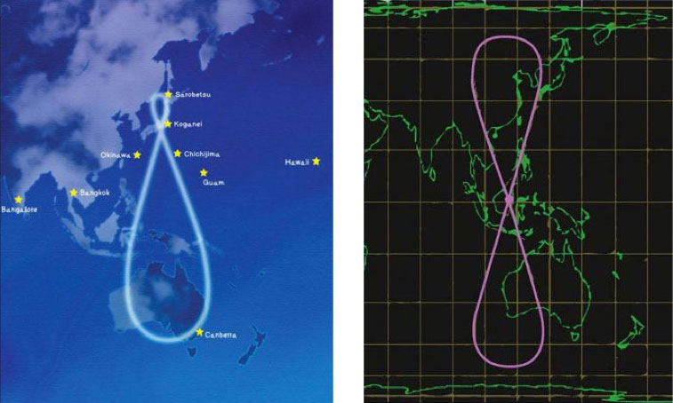
Multi-GNSS Campaign. An international collaboration is poised to take advantage of a coming proliferation of satellites, led by Compass and QZSS but also including GPS, GLONASS, and Galileo, over the Asia/Pacific region. The website www.multignss.asia/campaign.html states, “The Asia and Oceania region is a unique place where the number of usable modernized navigation satellites will increase much faster than other areas in the world. We will see great improvement of PNT capability and hence there is a great opportunity to try, test, and validate new receiver hardware, algorithms, and applications in order to address user requirements.”
The web page also carries an animation of the availability of more than 100 GNSS space vehicles that will operate over the region in the next decade. An initial campaign workshop in Bangkok, Thailand, in January drew 195 participants from 18 countries. A second workshop is scheduled for November 21–22 in Melbourne, Australia.
GLONASS September. Three GLONASS-M satellites to be launched on September 2 completed pre-launch testing and mating to the upper stage of the booster rocket at Baikonur Cosmodrome. Numbered 36, 37, and 38, the satellites will constitute the Block 42 triad.
GPS III Design: Done. The Lockheed Martin team developing GPS III has successfully completed the program’s Critical Design Review (CDR) phase, two months ahead of baseline schedule. CDR completion validates the detailed GPS III design to ensure it meets warfighter and civil requirements. It culminates many rigorous assembly, subsystem, element, space vehicle and system-level CDR events, validates the overall design maturity of the GPS III space vehicle, and allows Lockheed Martin to enter production phase. Col. Bernard J. Gruber, U.S. Air Force GPS Wing Commander, certified the completion. Lockheed Martin, ITT, and General Dynamics are working under a $3 billion development and production contract for up to 12 GPS IIIA satellites. The team is on track to launch the first GPS IIIA satellite in 2014.
GPS Interface Specs. New IS-GPS-200E, IS-GPS-705A, and IS-GPS-800A documents have been posted to www.gps.gov/technical.
SVN62 Rubidium Clock. The U.S. Naval Research Laboratory issued a preliminary report on the rubidium atomic clock currently in use on the SVN62 Block IIF satellite. While documenting excellent short-term performance, the report notes anomalous fluctuations in the clock signal with distinct 12-hour and 6-hour periodicities. The exact cause has not been identified although it is speculated that the fluctuations are of thermal origin like SVN-62’s L5 phase variance detected earlier. But note that the clock signal analysis relies only on L1 and L2 measurements.
GPS IIF Got Active. The 50th Space Wing’s 2nd Space Operations Squadron formally took over command and control of the first Block IIF satellite on August 26 from the GPS Wing, and the satellite was set healthy on August 27, making 31 healthy GPS satellites on orbit.
Advisory Board Update
GPS World Editorial Advisory Board member Art Gower has been elected a Lockheed Martin Fellow, an honor recognizing pre-eminent technical individual contributors in the company, delivering mission success and vision by undertaking the most difficult technical challenges facing the company and its customers. Art started his career with IBM Federal Systems Division (now part of Lockheed Martin Integrated Systems and Global Solutions) in 1983, developing displays and performing navigation upload and command and control system engineering for the GPS control segment, and becoming chief engineer for the GPS control segment in 1990. He has spent the majority of his career working on GPS, GNSS, and SBAS systems.
A Close Look at GPS SVN62 Triple-Frequency Signal Combinations Finds Carrier-Phase Variations on the New L5
By Oliver Montenbruck, André Hauschild (DLR/German Space Operations Center), Peter Steigenberger (Technische Universität München), and Richard B. Langley (University of New Brunswick)
The recently launched Block IIF satellite (SVN62/PRN25) is the first of a new generation of GPS satellites designed to transmit ranging signals for civil users on three frequencies: the C/A-code on L1 at 1575.42 MHz, the L2C-code on L2 at 1227.60 MHz, and the I5/IQ codes on L5 at 1176.45 MHz. Unlike L2, the L5 signal is located inside the protected Aeronautical Radionavigation Services (ARNS) band, which makes it specifically useful for safety critical aviation applications. In combination with the legacy L1 signal, civil aviation users can now perform ionospheric corrections without referring to the L2C signal. Compared to L2C, the new L5 signal offers a much higher chipping rate (the same as the encrypted P-code signal) of 10.23 MHz, which promises a lower ranging noise and better multipath resistance. L5 signals have already been transmitted for some time by the geostationary satellites of the United States’ Wide Area Augmentation System (WAAS) and are now about to become an integral part of the GPS constellation.
Following a short test transmission on June 17, 2010, the L5 signal was continuously activated on the morning of June 28. According to GPS officials, the checkout of the satellite is proceeding nominally and all signals have been found to fully comply with specifications. This will allow the satellite to be set healthy as soon as all commissioning tasks have been completed.
Scientists have long discussed the potential of new signals for multi-frequency, multi-GNSS applications, and expresed a great interest in signal combinations, particularly those of carrier-phase measurements, involving all three frequencies simultaneously. The use of triple-frequency combinations has, for example, been demonstrated to be of great interest for ambiguity resolution in precise carrier-phase-based positioning, for receiver autonomous integrity monitoring, and for ionospheric research (see the articles in Further Reading).
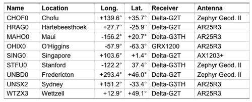
In consideration of the multitude of proposed applications for triple-frequency combinations, we took a close look at the quality of the new GPS L5 carrier-phase signal. For this purpose, we made use of measurements from the COoperative Network for GIOVE Observation (CONGO), jointly established by the German Federal Agency for Cartography and Geodesy (BKG) and the German Aerospace Center (DLR). CONGO is the first network of multi-constellation, multi-frequency GNSS receivers offering worldwide tracking of the SVN62 space vehicle on all frequencies (see Table 1).
Table 1. Subset of CONGO stations used for triple-frequency tracking of the new Block IIF satellite.
As suggested by Andrew Simsky (see Further Reading), the availability of carrier-phase measurements on three frequencies offers a particularly simple way to assess carrier-phase quality and multipath effects. By forming a linear combination
(1)
of the L1, L2, and L5 carrier-phase ranges with the additional conditions ,
a geometry- and ionosphere-free measurement is obtained, which reflects a weighted sum of the carrier-phase multipath and measurement noise on the individual frequencies. Here λ i with i = 1, 2, and 5, denotes the wavelength of the L1, L2, and L5 signals, respectively. Since the above conditions determine the factors α, β, and γ only up to an arbitrary scaling factor, we furthermore impose the normalizing conditions.
The latter condition ensures that the noise of the tri-carrier combination will match that of the individual carrier phases if the measurement noise is equal on all frequencies. As a result, we obtain the coefficients
with .
Introducing the carrier wavelengths of the L1, L2, and L5 signals, the coefficients attain the values (2)
It can be recognized that the tri-carrier combination is dominated by the L2 and L5 signals due to the proximity of their respective frequencies. Noise and multipath errors of L2 and L5 measurements are thus most prominently seen in the resulting combination, whereas any L1 phase errors are strongly attenuated.
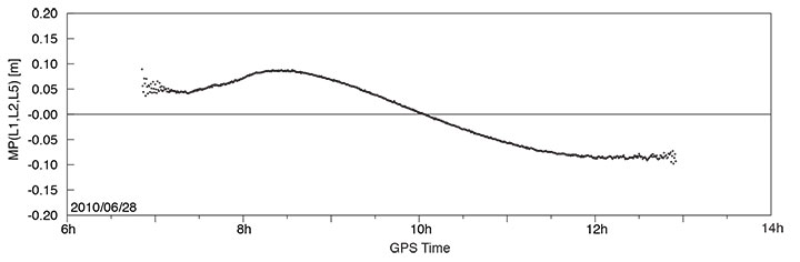
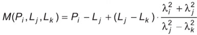
A long pass of L1, L2, and L5 code and phase measurements from the new Block IIF satellite was recorded by the O’Higgins station of the CONGO network shortly after the activation of the L5 signal generator on June 28. The SVN62 satellite was tracked for more than 6 hours and achieved a peak elevation angle of more than 75° on this date.
Figure 1 shows the resulting multipath combination computed from carrier-phase measurements of L1 C/A-code tracking, semi-codeless L2 P(Y) tracking (rather than L2C), and L5 I/Q tracking. The data have been leveled to a zero mean over the entire pass to remove the impact of the unknown carrier-phase ambiguities. Except at low elevation angles, near rise and set of the satellite where signal strengths are low, the tri-carrier combination shows a very low noise level that is consistent with the expected carrier-phase noise on all three frequencies. However, a pronounced long-term variation with a peak-to-peak amplitude of almost 20 centimeters may be recognized, which certainly comes as a big surprise and cannot be explained by local multipath. Frequency-dependent differences of the effective phase centers of the receiving or transmitting antennas can likewise be excluded, since these would result in a purely elevation-angle-dependent variation.
FIGURE 1. Triple-frequency (M=0.142·L1-0.767·L2+0.626·L5) carrier-phase multipath combination for SVN62/PRN25 tracking from the OHIX0 station on June 28.
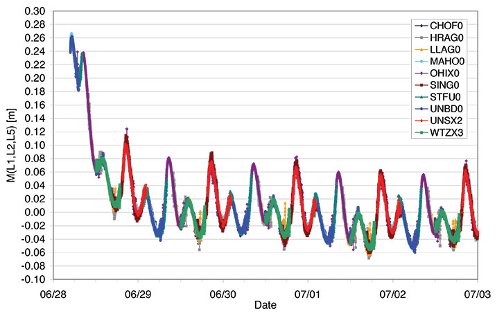
Looking at the entire set of measurements from all available CONGO stations, we could rapidly recognize that the variation of the tri-carrier combination with time is essentially the same for all stations with a common visibility of the SVN62 space vehicle, irrespective of the employed receiver and antenna. This suggests the presence of time-varying inter-frequency biases in the L1, L2, and L5 carriers transmitted by SVN62.
Thanks to the global distribution of the CONGO stations, the SVN62 space vehicle is always tracked by one or more stations, which enables a continuous monitoring of the L1/L2/L5 carrier-phase consistency. By adjusting the unknown offset of the tri-carrier combination for individual tracking arcs in such a way as to obtain a best match of consecutive and overlapping arcs, the variation can be traced over multiple days as shown in Figure 2. The graph shows a distinct orbital (that is, 12-hour) periodicity with a superimposed twice-per-revolution harmonic. In addition, a pronounced drift can be recognized for up to one day after activation of the L5 signal generator. Both observations suggest a temperature-dependent line bias in one or more carriers as a likely cause of the observed variation in the tri-carrier combination. (A line bias is a circuitry delay common in all observed satellites and is usually absorbed in the estimated clock offset.) However, an independent analysis of SVN62 temperature data from the onboard telemetry will be required to confirm the validity of this assumption. The space vehicle is in a deep eclipse orbit right now and therefore experiences substantial changes in its thermal conditions. However, the extreme points of the carrier-phase variation in Figure 2 are slightly shifted with respect to the local space vehicle noon (at 01:30 and 13:30 UTC) and the eclipse intervals (07:00–08:00 and 19:00–20:00 UTC).
FIGURE 2. Triple-frequency carrier-phase combination (M=0.142·L1-0.767·L2+0.626·L5) for the first five days of L5 activation on SVN62. The curve has arbitrarily been shifted to obtain a near-zero mean during the final days of the entire arc.
While the tri-carrier combination provides a very sensitive measurement for the analysis of differential delays between the individual carriers, it does not allow us to uniquely attribute the observed variations to one of the three signals. We therefore made use of code measurements (pseudoranges) to further investigate the consistency of specific sets of measurements. Since the observed variation of the tri-carrier combination exhibits an amplitude comparable to the noise level of the code measurements, a suitably chosen code-carrier combination can indeed help to identify which signal or signals are affected by line-bias variations. To this end, we consider a generalized form
of the well-known code-multipath combination, in which we difference the code measurement Pi at frequency i with an ionosphere-corrected combination of carrier-phase ranges Lj and Lk at frequencies j and k. In so doing, we remove geometric contributions along with clock and atmospheric variations, leaving primarily code multipath, receiver noise, and any signal perturbation that is not coherent on the involved frequencies. In the traditional case of dual-frequency tracking, the frequency of one of the involved carrier-phase measurements is necessarily identical to that of the code measurements. With triple-frequency tracking, in contrast, we are free to consider a larger variety of combinations. For the analysis of the SVN62 signals, we have specifically evaluated the L5 code-multipath combination using (a) the L5 and L1 carrier phases
and (b) the L2 and L1 carrier-phase measurements
The results shown in FIGURE 3 reveal a dramatic difference, which clearly hints at the L5 carrier as the main source of the observed carrier-phase variations.
FIGURE 3. L5 code-multipath combination formed with L1/L5 carrier-phase measurements (top) and with L1/L2 carrier-phase measurements (bottom). The figure is based on SVN62 tracking from the O’Higgins station and covers the same arc as considered in FIGURE 1.
In the first case, a variation close to that of Figure 1 is obtained, albeit with a 5–6 times larger amplitude that reflects the different weighting of the L5 carrier phase in the corresponding measurement combinations. A good consistency, in contrast, is obtained for the L5 code measurements when differenced against the ionosphere-corrected combination of L1 and L2 carrier-phase measurements.
Overall, we may conclude that the L5 carrier of the SVN62 space vehicle exhibits quasi-periodic line-bias variations with an amplitude of about 10 centimeters in relation to the L1 and L2 carriers. The L5 code measurements, in contrast, appear to be consistent with both the code and phase measurements on L1 and L2 at the respective noise levels. Further observations at a later time will be required to see whether the observed amplitude of the L5 phase variation is specific to the current eclipse orbit and whether it will possibly become lower when a higher angle of the Sun with respect to the orbital plane (the so-called beta-angle) is achieved.
What are the possible consequences of the L5 phase-bias variations for users of the new L5 signal? Evidently, new positioning services building on the L5 code measurements (and possible combinations) will not at all be affected! Even in the case of carrier-phase smoothing, the smoothing time scale will be much shorter than the periodicity of the carrier-phase bias variation. The L5 code measurement quality itself is well within the system specification and no concerns exist that would prevent the satellite from soon being declared healthy.
With respect to carrier-phase-based positioning applications, it is important to note that the L5 line bias acts like an additional frequency-specific satellite-clock offset. This has, for example, been confirmed in preliminary tests of SVN62 orbit determination conducted by the Technische Universität München. Orbit solutions using L1 and L5 measurements from the CONGO network differed by typically 15 centimeters (3D root-mean-square error) from reference orbits obtained by the Center for Orbit Determination in Europe analysis center using the IGS L1/L2 receiver network. At the same time, however, the L1/L5-based clock solutions showed a periodic offset from the L1/L2-based values that reflects the same variations as the tri-carrier combination discussed above.
As a common error for all receivers, the L5 line bias fully cancels in differential processing. Care must be taken though, that satellite clock offsets derived from L1/L2 carrier-phase observations cannot be employed for precise point positioning using L1/L5 measurements without explicit consideration of the inter-frequency carrier-phase bias. Likewise, efforts to correct second order ionospheric effects through the use of triple-frequency measurements are likely to suffer from an imperfect knowledge of the L5 bias and its variation with time.
Whereas some of the proposed ideas for triple-frequency processing may be difficult to materialize at present, a better characterization of the SVN62 L5 signal will certainly help to exploit the available benefits of the new signal and to establish refined processing schemes for scientific and other demanding applications. A continued monitoring of the L5 line bias and its variation with time is therefore deemed necessary and should be supported by a large number of suitably equipped tri-band GNSS monitoring stations.
— Oliver Montenbruck, Andre Hauschild (DLR/German Space Operations Center), Peter Steigenberger (Technische Universität München)
Richard B. Langley (University of New Brunswick)
Acknowledgment
The authors are grateful to Tom Stansell and Col. David Goldstein from the GPS Wing for early discussions and their independent assessment and interpretation of the SVN62 triple-frequency carrier-phase data.
Equipment
The CONGO network makes use of JavadTriumph Delta-G2T/G3TH and LeicaGRX1200+GNSS GNSS receivers for tracking GPS signals on the L1, L2, and L5 frequencies. The stations are equipped with TrimbleZephyr Geodetic II or LeicaAX1203+GNSS and AR25R3 antennas.
Further Reading
“The WAAS L5 Signal: An Assessment of Its Behavior and Potential End Use,” by H. Rho and R.B. Langley in GPS World, Vol. 20, No. 5, May 2009, pp. 42–50.
“Using Multi-Frequency for GPS Positioning and Receiver Autonomous Integrity Monitoring” by Y.-H. Tsai, F.-R. Chang, W.-C. Yang, and C.-L. Ma in Proceedings of the 2004 IEEE International Conference on Control Applications, Taipei, Taiwan, September 2–4, 2004, pp. 205–210.
“Triple Frequency Ambiguity Resolution Using GPS/Galileo” by O. Julien, M.E. Cannon, P. Alves, and G. Lachapelle in European Journal of Navigation, Vol. 2, No. 2, May 2004, pp. 51–57.
“Three’s the Charm — Triple Frequency Combinations in Future GNSS” by A. Simsky in Inside GNSS, Vol. 1, No. 5, July/August 2006, pp. 38–41.
“Total Electron Content Monitoring Using Triple Frequency GNSS Data: A Three-Step Approach” by J. Spits and R. Warnant in Journal of Atmospheric and Solar-Terrestrial Physics, Vo. 70, No. 15, December 2008, pp. 1885–1893, doi:10.1016/j.jastp.2008.03.007.
It has long been accepted that we may reasonably expect any new technical device to have some growing pains. If you examine the history of the space program you will discover evidence of this. In the case of the first GPS IIF vehicle on orbit we do not have a 12,552-mile screwdriver. but we do have dedicated software and systems engineers at Boeing and in the U.S. Air Force that will solve the issues that crop up and eventually present the world with a stable PNT platform.
I bring this to your attention because researchers at the German Aerospace Center (DLR) say they have found a small variance in the L5 signal on IIF-1. The signal variation results in no more than a 5-centimeter error with a predictable periodicity of about six hours. While observing the IIF, DLR also reports that the signal appears to be “hot” or stronger than anticipated or advertised by about 1/2 db.
Initial reaction from the GPS Wing and Air Force experts at Schriever AFB is that the signal fluctuation appears to be temperature-related, as the periodicity correlates directly to the temperature extremes the satellite is experiencing at this time of year in its MEO orbit. It is being investigated as a matter of course during the standard checkout of the satellite, which will continue for about another four weeks according to the original checkout schedule.
The GPS Wing is confident that all the IIF signal specifications will be met by the time the satellite is set healthy in about a month’s time and they will be able to move forward with the IIF launch schedule as planned. Obviously this could be perturbated by having to make corrections or adjustments to the satellites still to be launched, but this is normal procedure, and some leeway to correct anomalies is built into the schedule for the first few launches of any new satellite system.
Privately, one official commented, “It turns out that no one has ever made this measurement before. The Galileo SVs can only broadcast from 2 transmitters at a time so they are combining two E5 signals generated from the same transmitter. Furthermore, their data was collected during max Beta meaning when they weren’t in eclipse (less thermal variance).”
The press release from the GPS Wing reads as follows.
SMC Update. July 19 — “Officials from the Air Force Space Command, Space and Missile Systems Center’s Global Positioning Systems Wing announced the “on-orbit checkout” of the first IIF satellite is progressing as scheduled. “Nearing the half way point of its 90-day checkout period, GPS IIF SV-1 also known as SVN 62/PRN 25, is currently broadcasting the same L1 and L2 signals as previous GPS satellites and the new safety of life signal known as L5. All three signals being broadcast from SVN 62 are set unhealthy while experts monitor the quality and characteristics of the signals and the performance of the satellite.
“During the initial phase of testing, [DLR] combined L1, L2, and L5 signals in a technique used to characterize a number of known and modeled error sources from the signals. This three-frequency combining technique helps isolate “other” sources of location error, such as multi-path (when more than one path exists for signals to travel before reception), receiver errors, satellite induced errors and unmodeled phenomena. The L1, L2 and L5 signals from SVN-62 are operating nominally but DLR noticed higher residual errors than expected compared to previous somewhat similar measurements from Galileo’s GIOVE-A R&D satellite.
“The GPS Wing at Los Angeles Air Force Base has corroborated DLR’s results and is investigating root cause to share a deeper understanding of this new signal’s behavior with the user community. The causes of the phase variation are still being investigated, but they are likely the result of sensitivities to changes in the satellite’s thermal environment. SVN 62/PRN 25 is currently experiencing periods of both sunlight and total darkness (known as eclipse season) as the satellite orbits the Earth and traverses through Earth’s shadow. Tests to characterize the satellite’s performance during continuous sunlight exposure will continue after the current eclipse season ends later this month.
“Typical GPS receivers using stand-alone (single signal – L1, L2 or L5) or combinations of L1, L2 and L5 signals as part of their navigation solution will not be affected by this small phenomenon. The Air Force is committed to maintaining excellence in GPS navigation and timing services and to working with the user community to best use and exploit the new modernized GPS signals.
“When tests of this new generation of GPS satellites have been completed and Air Force leadership gives approval, the satellite signals will be set healthy and will operate as specified in the Interface Control Documents (ICDs).”
In a few weeks, we will again observe the tragic anniversary of the 9/11 attacks on the United States. This will mark nearly a full decade since that terrible day that changed the lives of people around the world, forever. Many will remember. Many will mourn. Many will work to ensure that such an event never again threatens any nation. That is a good thing.
Few outside the position, navigation, and timing (PNT) community will also recall that the day before the 9/11 attacks, the U.S. government released a landmark document that described the vulnerabilities of services provided by GPS to disruption, whether by attack or inadvertent interference. The Department of Transportation Volpe Center’s GPS vulnerability assessment recommended that services utilizing GPS-provided PNT seek alternative sources of these services. What decisions and actions have the findings and recommendations of this report promoted? The answer is most disturbing.
The U.S. government has sealed the fate of Loran-C and kept the decision on an enhanced Loran system (eLoran) in limbo for more than 10 years. The government has spent hundreds of thousands (if not millions) of dollars studying the problem over and over again and either ignoring or classifying the results. The Department of Homeland Security (DHS), a direct outcome of the 9/11 attacks, has done nothing to address the need for a national backup other than study and re-study the problem and disregard the findings and warnings of world-class PNT experts.
On the positive side, a recent paper from the Federal Aviation Administration (FAA) attempts to address the problem by proposing to investigate alternative PNT (APNT). While the FAA does this under its Title 49 responsibility and authority to ensure the safety, security, and efficiency of our National Airspace System (NAS), and the alternatives it is looking at are certainly aviation-centric, it is admirable that somewhere in this government someone is finally moving forward to define and implement a real, operational PNT alternative to GNSS and its augmentations. [An abridgement of the FAA paper appeared in the July GPS World; the full paper is available here.]
I applaud the FAA’s actions and only hope that bureaucrats and bureaucratic processes don’t penalize it for its efforts.
But the question remains: When will a decision on the U.S. national PNT backup be made? The urgency of this issue can be highlighted by posing some simple questions about another current threat to the U.S. infrastructure and economy.
To what extent are GNSS-provided PNT services being used to identify the amount and movement of the oil in the Gulf of Mexico? What level of information exactness/integrity would be lost if GNSS-provided PNT services were not available?
To what extent are GNSS-provided PNT services being utilized by cleanup crews and other impact-mitigation services? How would the efficiency of the cleanup/mitigation activities be impeded if GNSS-provided services were not available?
Finally, what is the opportunity cost of not having a national PNT backup? Why has this decision been so hard to make? One would intuit that it has encountered political obstacles, not scientific ones. What are they, exactly?
While the FAA is doing what it must to ensure a safe, secure, and efficient national airspace, what about the rest of us? The boaters, the truckers, the farmers, the power transmission people, the telecom providers, the cell-phone users? The list goes on and on.
It has been nine years. Why is this so hard?
As we take time on September 11 to remember where we were when we heard the news, to mourn those lost, and to do, each in our our way, something to ensure that such a thing never happens again, we should also take time on September 10 to thank the folks at the Volpe Center for their important efforts. And we should try, each in our own way, to do something to ensure that the effects of a loss of GNSS-provided services will be once and for all properly mitigated.
The masked engineer harbors strong convictions, matched by a desire to hold onto a day job.
By Oliver Montenbruck, Andre Hauschild (DLR/GSOC), Stefan Erker, Michael Meurer (DLR/IKN), Richard B. Langley (UNB), and Peter Steigenberger (TUM)
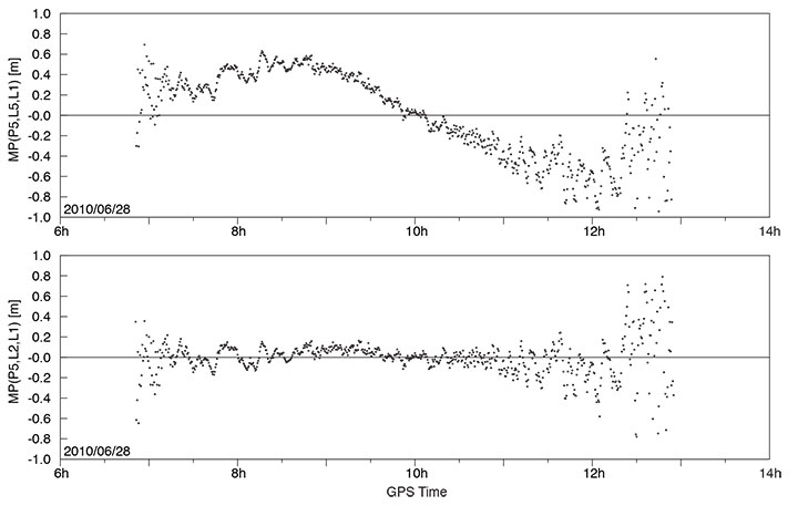
The L5 signal of the new Block IIF satellite shows a very favorable signal strength (Fig. 1), which is somewhere in between the L1 and L2C signal strength for the employed antenna and slightly higher than that of the GIOVE-A/B satellites. While the L5 test signal of the second-last Block IIR-M satellite (PRN1/SVN49) is transmitted through a narrow beam antenna and shows a steep variation with elevation angle, the new satellite exhibits an almost constant flux irrespective of the boresight angle.
Following the successful launch of the first Block-IIF GPS satellite (PRN25/SVN62) on May 28, 2010 (UTC), and the activation of the legacy signals on June 6, users around the world have eagerly awaited the first transmission of PRN25 signals in the L5 band.
In June, at last, the L5 payload was activated for more than five hours transmitting nominal signals with the PRN25 ranging code. This enabled standard tracking receivers to collect the first real L5 measurements from the new satellite.
Scientists of the German Aerospace Center (DLR), the University of New Brunswick (UNB), and the Technische Universität München (TUM) spotted the first L5 data at 15:17:11 UTC from a station in Fredericton, Canada, followed a second later by stations in Japan, Singapore, the Canary Islands, and Germany. The stations are part of the CONGO network, which is the first global network of tri-band (L1/E1, L2, L5/E5a) GNSS receivers monitoring the GPS, GLONASS, GIOVE, and SBAS satellites. For background on the CONGO network, see the September 2009 GPS World article.
Fig.1 Carrier-to-noise-density ratio of GPS (left) and GIOVE-A/B signals measured at the Wettzell station on June 17, 2010. Red curves refer to signals in the L5/E5a band and include data from the PRN1 test satellite and the new PRN25 satellite.
The L5 signal of the new Block IIF satellite shows a very favourable signal strength (Fig. 1), which is somewhere in between the L1 and L2C signal strength for the employed antenna and slightly higher than that of the GIOVE-A/B satellites. While the L5 test signal of the second-last Block IIR-M satellite (PRN1/SVN49) is transmitted through a narrow beam antenna and shows a steep variation with elevation angle, the new satellite exhibits an almost constant flux irrespective of the boresight angle.
Fig. 2 Multipath plots of L1 C/A code, semi-codeless L2 P(Y) code, and L5 code tracking for the Singapore station of the CONGO network (10-second smoothing).
While the new Block IIF satellite has not yet been set healthy and made available for public use, the early measurements collected on June 17 already demonstrate good tracking quality. This is illustrated in Fig. 2, showing the so-called multipath combination for pseudorange measurements from L1 and L2 legacy signals (the upper two panels) as well as the new L5 signal for Singapore, which had continuous visibility of PRN25 during the period of interest. Except for low elevation angles that are affected by strong multipath from structures in the vicinity of the antenna, root-mean-square tracking errors well below 30 centimeters were obtained for all signals.
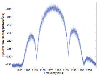
Fig. 3 L5 spectrum of PRN25 collected on June 17, 2010 with a 30-meter high-gain antenna at Weilheim, Germany.
In addition, the GNSS signal monitoring facility at DLR’s ground station in Weilheim has been used to record high-rate radio-frequency samples and spectra of the new signal, a snapshot of which is shown in Fig. 3. The raw sampling also confirmed that the L5 signal of PRN25 comprises both in-phase and quadrature modulation (in contrast to the PRN1 test signal, which contains a Q-component, only).
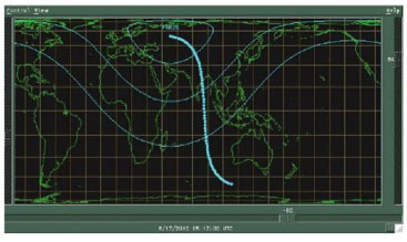
To the regret of U.S. scientists, the first publically traced L5 signals were only transmitted when the satellite was over Europe and Asia (see Fig. 4). Nevertheless, the test transmission provided an excellent sneak preview of what we can expect when the regular transmission starts. The satellite is presently expected to be set healthy and to start regular service by the end of August at the latest.
Fig. 4. The ground track of PRN25 during the transmission of L5 signals on June 17, 2010. Also indicated is the footprint of the satellite showing the 0°, 30°, and 60° elevation angle contours at the beginning of the transmission. The ground track is almost centered over Diego Garcia, one of the GPS monitoring stations.
Equipment. The CONGO network stations use JAVAD GNSS Triumph Delta-G2T/G3TH receivers. A Leica AR25R3 chokering antenna is used at Wettzell, while the Singapore station is equipped with a Leica AX1203+ GNSS antenna. The L5 spectrum was recorded with an Agilent PSA E4443A vector signal analyzer.
Beidou G3
China launched another Beidou/ Compass satellite, named G3, on June 2. By June 9, its apogee kick motor had placed the satellite in geostationary orbit at 84°38’ east, according to NORAD tracking reports.This is close to the position initially occupied by G2 (83°30’) before it started drifting. By June 9, G2 had drifted to 64°29’. By June 11, G3 had started transmitting signals on three frequencies.
China now has two properly functioning geostationary satellites in its second-generation system, out of a total of five it expects to place by 2012 for a regional operating system; also needed for this concept are four mid-Earth orbit satellites (one currently aloft), and five inclined geosynchronous orbit satellites (zero in orbit now). A planned global system would require 5, 27, and 3 satellites in GEO, MEO, and IGO orbits, respectively, by 2020.
Current regional-system signals on three frequencies use quadrature phase shift keying. Global-system signals will be binary offset carrier waveforms.
Opinions on SVN-49
The public comment period on proposed mitigation options for GPS satellite IIR-20M (SVN-49) ended May 28, and comments are viewable at www.regulations.gov under RITA Docket 2010–0002. Among others, the U.S. GPS Industry Council, NovAtel, Garmin, Septentrio, Raytheon, Boeing Commercial Airplanes division, General Motors OnStar, the European Commission, the MITRE Corporation, STMicroelectronics, the German Space Operations Center, and Cessna Aircraft have all filed comments expressing a preference for one option or another.
Unfortunately for the U.S. Air Force and the GPS Wing, no clear consensus emerges. Indeed, differences of opinion naturally follow the respective orientation of each company or organization toward their customers’ or members’ specialized needs.
Devote It to Science. Perhaps in recognition of this imbroglio, at the Air Force Space Command- Industry Exchange on June 15, Lt. Colonel Todd Parks briefed the PNT Functional Capability Team, explaining that the Air Force now was soliciting from industry “innovative applications” for the SVN-49 signal in space.This echoes a suggestion by Javad Ashjaee at last year’s unprecedented ION/ USAF session on SVN-49, where he proposed that the signal be used for studying multipath.
A website article at env-gpsworld-integration.kinsta.cloud/49opinions recaps commentary and preferred options from several companies and organizations.
The potential mitigations are each designed to reduce the impact of the unique nature — that is, errors — of the SVN-49 signal to a portion of the user segment. They are (so far):
1. Set healthy with current 152- meter antenna phase center (APC) and associated clock offsets.
2. Set healthy with factory APC offset.
3. Users switch to multipath-resistant receivers.
4. Modify receiver software to use look-up table corrections.
5. Increase user range accuracy (URA) index to a minimum value of 3.
6. Remove data modulation from L2 P(Y)-code, and
7. Change L2C PRN code to a “unique sequence.” (6 and 7 are considered a pair, to be jointly implemented for desired effect.)
8. Change SVN-49 from PRN-01 to PRN-32.
9. Use spare health code so future users could use SVN-49 despite unhealthy setting. For background on the SVN-49 situation, see Richard Langley’s Expert Advice column from August 2009. Briefly, the pseudorange data broadcast by the satellite contains larger than normal errors that vary according to the elevation of the satellite above the horizon.
The comments filed by the U.S. GPS Industry Council (USGIC), available as a PDF file at both URLs listed in this story, are the most detailed and extensive across all the options. However, the stated preference of the USGIC for Option 9 does not necessarily reflect agreement across all sectors of industry. As the USGIC points out, “Options 1 through 8 propose to designate SVN 49 as healthy using techniques that enable mitigation for some user applications, but that are unable to also mitigate adverse impacts to otherusers.”
Multiple Constellation Processing in the International GNSS Service
By Tim Springer and Rolf Dach
Does combining GPS and GLONASS observations make a difference? The International GNSS Service (IGS) has been providing such data for several years. Representatives from two IGS analysis centers discuss the past, present, and future of IGS GNSS monitoring and product development.
INNOVATION INSIGHTS by Richard Langley
ARE WE THERE YET — at a multiple-constellation GNSS world? The European Galileo system only has two test satellites in orbit, with constellation completion not scheduled until 2014. The Chinese Beidou/Compass system has launched some test satellites, but global coverage is not promised until 2020. And the first Japanese Quasi-Zenith Satellite System space vehicle is scheduled for launch this year with the system not fully operational until 2013. So, does this mean GPS is still the only game in town? No, not by a long shot. We have overlooked Russia’s GLONASS.
Standing for Global’naya Navigatsionnaya Sputnikova Sistema, GLONASS was conceived by the former Soviet Ministry of Defence in the 1970s, perhaps as a response to the announced development of GPS. The first satellite was launched on October 12, 1982. But because of launch failures and the characteristically brief lives of the satellites, a further 70 satellites were launched before a fully populated constellation of 24 functioning satellites was achieved in early 1996. Unfortunately, the full constellation was short-lived. Russia’s economic difficulties following the dismantling of the Soviet Union hurt GLONASS. Funds were not available, and by 2002 the constellation had dropped to as few as seven satellites, with only six available during maintenance operations! But Russia’s fortunes turned around, and with support from the Russian hierarchy, GLONASS was reborn. Longer-lived satellites were launched, as many as six per year, and slowly but surely the constellation has grown to 21, with two in-orbit spares.
But are there any users outside Russia? Although dual-system GPS/GLONASS receivers have been around for at least a decade, manufacturers have taken notice of GLONASS’s recent phoenix-like rebirth. All of the high-end manufacturers now offer receivers with GLONASS capability. Does combining GPS and GLONASS observations make a difference? You bet — just ask any surveyor who uses both systems in the real-time kinematic (RTK) approach. Scientific applications requiring high-accuracy satellite orbit and clock data also benefit. The International GNSS Service (IGS) has been providing such data for several years, and in this month’s article representatives from two IGS analysis centers discuss the past, present, and future of IGS GNSS monitoring and product development.
So, getting back to our question, are we there yet? Many early adopters of GPS plus GLONASS data and products would reply with a resounding “yes.”
“Innovation” features discussions about advances in GPS technology, its applications, and the fundamentals of GPS positioning. The column is coordinated by Richard Langley, Department of Geodesy and Geomatics Engineering, University of New Brunswick.
In 2005, the International GPS Service (IGS) was renamed the International GNSS Service. With this change, the IGS governing board and the IGS community expressed their expectation to extend activities from the well-established GPS to other active and planned global navigation satellite systems such as GLONASS, Galileo, and Compass. Meanwhile, the GLONASS satellite constellation, as well as the IGS GNSS tracking network, have evolved significantly. Since 2003, the GLONASS satellite constellation has been improving steadily, leading to the current, May 2010, constellation with 21 operational satellites and two in-orbit spares. And starting in 2008, the GNSS capabilities of the IGS tracking network have been greatly enhanced giving rise to a truly global GNSS tracking system with more than 100 GNSS (GPS plus GLONASS) receivers. The almost-complete GLONASS satellite constellation, coupled with a readily available global tracking network with high-quality receivers, have greatly increased the interest in and need for GNSS products such as precise satellite orbit ephemerides. However, the IGS analysis center products are still mainly GPS-only. Only two analysis centers provide true multi-GNSS solutions. Two analysis centers provide GLONASS-only solutions (a GLONASS combined IGS product is available but without accurate clocks). No combined IGS GNSS product exists. In view of the large interest from the user community, this is a really disappointing situation. In particular, because experiences gathered with handling GPS plus GLONASS will make the incorporation of other GNSS such as Galileo, Compass, and the Quasi-Zenith Satellite System (QZSS) that much easier.
However, during a meeting of the IGS analysis centers in December 2009, it became clear that many of the centers had started to implement and enhance the GLONASS processing capabilities in their software. This was happening as a direct consequence of the improvements in the GLONASS constellation, the IGS GNSS tracking network, and increased user interest (if not demand). Throughout 2010 and 2011, we will therefore see a significant increase in the number of true GNSS solutions within the IGS. A very positive development for the GNSS world.
In this article, we give an overview of the recent developments in the area of multi-GNSS processing within the IGS in general, but with a focus on the activities of the two analysis centers in the IGS that are leading the GNSS efforts: the Center for Orbit Determination in Europe (CODE) and the European Space Operations Center (ESOC) of the European Space Agency.
Why GNSS?
Within the IGS, we are often confronted with the question: Why GNSS? Why should I go through the burden of adding GNSS capabilities to my software, having larger processing loads, and so on, for little or no benefit? Well, from an IGS analysis center point of view, this question is valid. The accuracies achieved with GPS alone are so good that there will be little visible benefit of including another system. Nevertheless, there are indeed benefits.
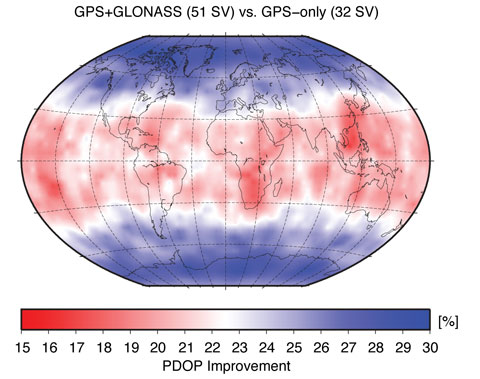
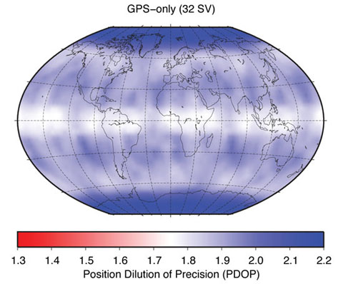
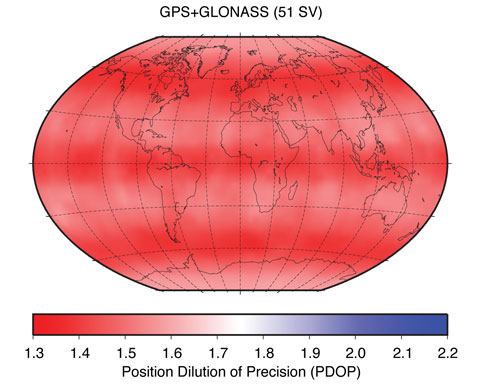
There is a large number of users worldwide who would see benefits of using GNSS products compared to GPS-only products. Clearly, all real-time users will benefit enormously from the increased number of satellites. Figure 1, showing the so-called position dilution of precision (PDOP), demonstrates this very clearly. The two panels in Figure 1 show the GPS-only PDOP and the GPS-plus-GLONASS PDOP using the satellite constellation of May 3, 2009.
FIGURE 1A. Effect of GLONASS on position dilution of precision.FIGURE 1B. Effect of GLONASS on position dilution of precision.
Figure 2 shows the PDOP improvement in percentage when comparing the GPS-only to the GPS-plus-GLONASS PDOP values. At high latitudes, that is, above 55 degrees, the improvement is at the 30 percent level. At mid-latitudes, the improvements are still well above 15 percent, demonstrating the significant improvements real-time GNSS users may expect compared to real-time GPS-only users.
Figure 2. Position dilution of precision improvement using GLONASS.
With the current GPS constellation, daily solutions are not limited by the number of available satellites, but rather by the analysis models (such as that for the troposphere), calibration uncertainties (such as models for antenna phase-center variation), and environmental effects (such as multipath). For these reasons, IGS-like processing strategies, in which data from reference stations are processed in 24-hour batches, will not show clear benefits from adding data from more satellites and other systems.
However, besides real-time users, users at high latitudes (including the whole of Canada and most of Europe) will see improvements. Recently, several researchers have noticed that for latitudes higher than 50 degrees, the addition of GLONASS brings benefit. This is, of course, thanks to the higher orbital inclination of the GLONASS satellites (about 64 degrees) compared to the inclination of the GPS satellites (about 55 degrees), which is also very nicely demonstrated in the PDOP (see Figure 1). So, from a service point of view — the “S” in IGS — there is a clear need to provide GNSS solutions to the user community. Besides offering significant benefits in terms of accuracy, the increased number of satellites will also make solutions more reliable and robust. The completely different repeat cycle of the GLONASS satellite orbits is especially important as it changes the sensitivity to multipath completely. Multipath effects in GPS-only data repeat almost perfectly from day to day with a 4-minute time shift giving rise to spurious, near yearly signals in GPS time series. Satellites from other constellations, such as GLONASS, introduce other system-related frequencies, which results in a general reduction of such GNSS-induced frequencies in a multi-GNSS solution.
Because of the constellation design, each GPS satellite follows its own ground track in each orbit cycle. That means that at a ground station, each GPS satellite is observed on one and the same track each day so that a systematic influence of a satellite (such as a mismodeling of the satellite antenna position with respect to the satellite’s center of mass) has a systematic effect on the obtained (daily) station positions. This systematic translation of satellite-related errors into station-related parameters doesn’t happen for any other GNSS constellation.
IGS GNSS Analysis Centers
A detailed description of the IGS is beyond the scope of this article; an excellent overview was provided in an earlier Innovation column. We simply point out here that it is important to know that the IGS serves as the reference in many GNSS applications by providing data and products of the highest possible quality. Very well known and widely used are the tracking data from the IGS station network — the raw pseudorange and carrier-phase measurements — and the orbit and clock products of the GPS satellites. The IGS generates these products by combining the orbit and clock solutions of the individual analysis centers that contribute to the IGS. For the GPS-only products, 10 different analysis centers contribute to three different product series called the ultra-rapid, rapid, and final products. The final products deliver the highest possible quality but have the longest delay, as they become available 12 days after the end of the observation week. The rapid products are roughly comparable in quality to the IGS final products, but they are delivered daily with a delay of only 17 hours after the end of the observation day. The ultra-rapid products are delivered four times per day 3 hours after the end of the last used observation. For example, at 03:00 UTC, an ultra-rapid product is delivered that used data up to 00:00 UTC. It consists of two parts: an estimated part and a predicted part that may be used for real-time purposes. The quality of the estimated part is very similar to that of the rapid products. The predicted part is, of course, significantly less accurate, although the orbits have an astonishing precision of well below 30 millimeters — much better than that of the orbits in the satellites’ broadcast navigation messages.
In addition to these GPS-only products, there is also a GLONASS product. However, contrary to the GPS side of things, for GLONASS, only a final product is generated. Four analysis centers provide products for the IGS GLONASS combination: the Bundesamt für Kartographie und Geodäsie (BKG), Frankfurt am Main, Germany; CODE, based at the Astronomical Institute of the University of Bern, Switzerland; ESOC, Darmstadt, Germany; and the Information-Analytical Center (IAC) of Roscosmos, Moscow, Russia.
The analysis centers BKG and IAC determine the GLONASS satellite orbits, introducing the information for the GPS satellites from the IGS solution without further estimation. The analysis center CODE provides, since May 2003, orbits for GPS and GLONASS based on a rigorously combined analysis of the data of both GNSS, that is, a true multi-GNSS solution. Since January 2008, ESOC follows this strategy as well. From these four analysis centers, only two, ESOC and IAC, provide satellite clock estimates for the GLONASS satellites. This situation prevents the IGS from making a robust and reliable combined GLONASS clock product. With four analysis centers contributing to the orbits, the IGS can and does make an excellent GLONASS combined orbit product.
In our definition of true multi-GNSS solutions, the measurements from each system contribute to all relevant parameters to the same extent. This can only be achieved by the rigorous combined processing of the data from all available GNSS. The two-step approach, introducing the GPS solution when solving for the GLONASS orbits and satellite clocks, is regarded as an extension of a GPS-only solution to GLONASS. As the contributions from BKG and IAC in the IGS GLONASS product demonstrate, this two-step procedure provides excellent results.
From a user point of view, a big disadvantage is the fact that the IGS does not provide a real GNSS product. The IGS provides a high-quality GPS product and a high-quality GLONASS orbit product, but there is no combined GNSS product. Also, the IGS is only capable of generating final GLONASS products because only two analysis centers, CODE and ESOC, submit GNSS products for the rapid and ultra–rapid products. IGS policy requires contributions from at least three analysis centers for a meaningful and robust combined product.
Users of GNSS orbits and/or clocks therefore have to use the products of one of the individual analysis centers or combine the GPS-only and GLONASS-only products from the IGS. Here, the GNSS products of the CODE and ESOC analysis centers are clearly preferable over those of the IGS and other analysis centers since these are the only two true GNSS products that guarantee the full consistency between the two GNSS.
GLONASS Tracking Network
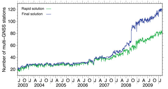
Until 2003, the IGS had established a GLONASS tracking network of merely 20 stations. In 2003, this number grew rapidly from 20 to 30, but after 2003 the number of stations remained stable for quite a long time with a very inhomogeneous distribution. For example, there were only a few stations in the whole western hemisphere. In 2006/2007, a new generation of combined GPS/GLONASS receivers became available, produced by several well–known GPS receiver manufacturers. With this new equipment available, the number of GLONASS tracking stations in the IGS network started to increase steadily. In 2008, the increase rate went up significantly (see Figure 3) and, more importantly, the global distribution of the receivers improved as, finally, significant numbers of stations started to emerge in both North and South America. Orbits and clocks of the GLONASS satellites are, since ear
ly 2009, determined from the data of more than 100 globally well-distributed tracking stations in the IGS network (see Figure 4). A good global distribution of observing sites is extremely important for orbit determination and even more so for the clock determination. Until early in 2008, the GLONASS clock determination suffered from gaps in the global tracking network, which had severe impact on the clock estimates. If tracking gaps cause an interruption of the carrier-phase tracking of a GNSS satellite, the clock estimates are basically reset and a jump will occur. The size of the jump is delimited by the accuracy of the code (pseudorange) observations, that is, at the 1-meter level, or 3 nanoseconds in clock terms.
We may state that today orbit and clock determination for the GLONASS satellites may be based on a truly global tracking network of high-quality geodetic–type receivers. This significant improvement is due to the efforts of many IGS station managers and their institutions.
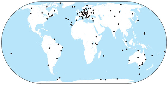
Figure 3. Number of sites in the IGS network providing GLONASS data, used for orbit determination at CODE.Figure 4. Current distribution of IGS combined GPS and GLONASS tracking stations.
GLONASS Constellation
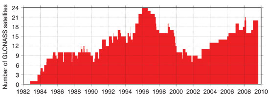
After reaching a full orbit constellation of 24 satellites in early 1996, the GLONASS constellation degraded rapidly due to Russia’s economic difficulties following the break-up of the Soviet Union coupled with the short lifetime of the GLONASS satellites. Since 2002, the GLONASS constellation has slowly but surely been rebuilt (see Figure 5). Currently, there are 21 active modernized GLONASS (GLONASS-M) satellites, which have a significantly longer lifespan compared to the original satellites. Additionally, there are two reserve satellites on orbit.
Figure 5. Development of the GLONASS satellite constellation since 1982.
Russia intends to have a full 24-satellite constellation in place by the end of 2010. To achieve this goal, two more triple-satellite launches are planned, one in August and one in November. The November launch could include a new type of GLONASS satellite, GLONASS-K. The GLONASS-K version is a lighter, unpressurized spacecraft, with a design lifetime of 10 years. In addition to the legacy frequency-division-multiple-access signals, it will transmit code-division-multiple-access signals and use an additional frequency band overlapping with the GPS L5 band.
Orbit and Clock Accuracy
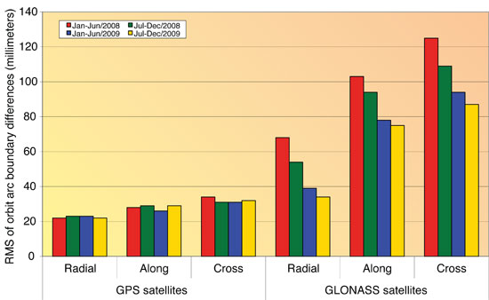
The developments of both the GLONASS tracking capabilities of the IGS station network as well as the steady increase in the number of GLONASS satellites has had a positive influence on the accuracy of the GLONASS orbits and clocks. It also has significantly increased the interest in the GLONASS system. The enhancement of the IGS GNSS tracking network from an almost purely European network to a truly global network between 2008 and now has had a significant impact on the quality of the GLONASS orbits and clocks. To show the effect on the quality of the GLONASS orbit estimates, we look at the difference between two independent consecutive solutions spanning 24 hours from 0 to 24 hours GPS Time. We compare the “midnight point” of both solutions, that is, the solution at the end of one day (or arc) and the beginning of the next day (or arc). This will give us a worst-case estimate for the orbit quality because typically the orbit is less accurate at the boundary of the orbital arc compared to the middle of the orbital arc. We have analyzed these orbit differences for all GPS and GLONASS satellites separately for four half-year time spans using the routine IGS GNSS solutions from ESOC. The differences are computed in three different satellite-orbit-related directions: radial, along-track, and cross-track. The times spans are:
January to June 2008 (6 months)
July to December 2008 (6 months)
January to June 2009 (6 months)
July to December 2009 (6 months)
The results are shown in Figure 6. For the GPS satellites, we cannot see any improvement over time. The quality of the GPS orbits is excellent at the 25- to 35-millimeter level for all three components.
Figure 6. Evolution of GPS and GLONASS orbit quality from January 2008 to December 2009.
Remember, we are looking at the worst-case differences here. For GLONASS, we can see a significant improvement over the four time spans. Early in 2008, the orbit quality was at the 120-millimeter level (cross-track), which has improved significantly to the 85-millimeter level. It is important to note that no processing changes were made during this time interval, and that the improvements are thanks to the improvements in the station tracking network and the GLONASS satellite constellation.
The clock quality is more difficult to assess, but over the timeframe of 2008 to 2009 we have noticed that the clock estimates of the GLONASS satellites have become complete. In 2008, with the still-far-from-global tracking network, there were many gaps in the tracking of the GLONASS satellites. This means that at some epochs no stations were tracking a GLONASS satellite. Such gaps cause jumps in the satellite clock estimates, because the carrier-phase observations become discontinuous, and these jumps are at the 1-meter (3-nanosecond) level. With the improvements of the IGS GNSS tracking network, the GLONASS tracking is now complete and clocks for all epochs are estimated. A comparison of the clocks of the two analysis centers that provide estimated clocks for the GLONASS satellites shows an agreement at the 80-picosecond level, which is only slightly worse than the agreement between the GPS clocks. Significant biases at the few-hundred-nanosecond level exist only in the GLONASS clocks because of receiver internal frequency-dependent delays. The ESOC GNSS orbit and clock products are, however, perfectly suited for precise point positioning using either GPS, GLONASS or, even better, both GNSS simultaneously. It should be noted that since February 2010, the ESOC IGS clock products are now sampled at 30 rather than 300 seconds, which further enhances their suitability.
Conclusions and Outlook
The IGS has promised to become a GNSS service by changing its name in 2005, more than four years ago. Meanwhile, the GLONASS satellite constellation as well as the IGS GNSS tracking network have matured and are practically complete. For the IGS to become a true GNSS service, a substantial number of the analysis centers should provide GNSS contributions to all IGS products: final, rapid, ultra-rapid, and real-time. These products should come from performing a rigorous combined analysis of the observations of all active GNSS satellites. It is expected that over the next two years, we will see a significant increase in the number of true GNSS solutions within the IGS, a very positive development for the GNSS world.
Within the IGS, the analysis centers CODE and ESOC are leading the GNSS efforts. CODE has provided fully consistent GPS/GLONASS products from a rigorously combined processing approach for all IGS products (final, rapid, and ultra-rapid) since May 2003, or for seven years. Since the beginning of 2008, ESOC has followed this good practice for its final products, and in February 2010 ESOC started to produce rapid and ultra-rapid GNSS products. A unique feature of the ESOC products is that they include the clocks for the GLONASS satellites, even with a sampling rate of 30 seconds for the final products. CODE will add GLONASS clocks to its IGS products very soon, during the fi
rst half of 2010. The GLONASS orbit and clock product quality has become comparable to that of the GPS products within the IGS. However, because GLONASS carrier-phase integer ambiguity resolution is difficult, the GLONASS products are and will remain somewhat less accurate than the GPS products.
The experiences gathered at CODE and ESOC by fully combining the observations from the GPS and GLONASS systems will pave the way for the integration of additional systems and signals within the IGS. Hence, IGS will retain its leading position in providing the reference, in the broadest sense of the word, for all GNSS. In the near future, this means the integration of QZSS and Galileo observations as well as the integration of the new triple-frequency signals from the latest generation of GPS satellites, Block IIF, the first of which was scheduled for launch last month.
The positive GNSS developments within the IGS will require an update of the IGS combination software to enable a true GNSS combination. The CODE and ESOC analysis centers have indicated that they are interested in taking on this important task of rewriting and enhancing the IGS orbit and clock combination software to make the IGS a true GNSS service.
Acknowledgments
CODE is a collaboration among the Astronomical Institute, University of Bern (Bern, Switzerland), the Swiss Federal Office for Topography (Wabern, Switzerland), the Bundesamt für Kartographie und Geodäsie (Frankfurt am Main, Germany), and the Institut für Astronomische und Physikalische Geodäsie of the Technische Universität München (Munich, Germany).
The authors are very grateful to the IGS and its numerous contributors for providing the global GNSS tracking data network.
TIM SPRINGER received his Ph.D. in physics from the Astronomical Institute of the University of Bern (AIUB) in 1999. He has been a key person in the development of the Center for Orbit Determination in Europe (CODE), one of the IGS analysis centers, located at AIUB. Since 2004, he has been working for the Navigation Support Office (OPS-GN) at the European Space Operations Centre (ESOC) of the European Space Agency (ESA) in Darmstadt, Germany. In this group, he has led the development of the new ESOC GNSS software, which is used for most GNSS activities at OPS-GN, including GIOVE-A and -B analyses.
ROLF DACH received his Ph.D. in geodesy at the Institut für Planetare Geodäsie of the University of Technology in Dresden, Germany. Since 1999, he has been working as a scientist at AIUB, where he is head of the GNSS research group. He oversees the development of the Bernese GPS Software, used at CODE for activities in the frame of the AIUB IGS analysis center and elsewhere.
“Renovated GLONASS: Improved Performances of GNSS Receivers” by A.E. Zinoviev, A.V. Veitsel, and D.A. Dolgin in Proceedings of ION GNSS 2009, the 22nd International Technical Meeting of the Satellite Division of The Institute of Navigation, Savannah, Georgia, September 22–25, 2009, pp. 3271–3277.
“Other Satellite Navigation Systems” by S. Feairheller and R. Clark, Chapter 11 in Understanding GPS: Principles and Applications, 2nd edition, edited by E.D. Kaplan and C.J. Hegarty, published by Artech House, Boston, 2006.
“GLONASS Performance, 1995–1997, and GPS-GLONASS Interoperability Issues” by G.L. Cook in Navigation, Vol. 44, No. 3, Fall 1997, pp. 291–300.
“GLONASS Review and Update” by R.B. Langley in GPS World, Vol. 8, No. 7, July 1997, pp. 46–51.
• The International GNSS Service
“The International GNSS Service in a Changing Landscape of Global Navigation Satellite Systems” by J.M. Dow, R.E. Neilan, and C. Rizos in Journal of Geodesy, Vol. 83, No. 3-4, March 2009, pp. 191–198, doi:10.1007/s00190-008-0300-3; erratum: Vol. 83, No. 7, July 2009, p. 689, doi: 10.1007/s00190-009-0315-4.
“GNSS Processing at CODE: Status Report” by R. Dach, E. Brockmann, S. Schaer, G. Beutler, M. Meindl, L. Prange, H. Bock, A. Jäggi, and L. Ostini in Journal of Geodesy, Vol. 83, No. 3-4, March 2009, pp. 353–365, doi:10.1007/s00190-008-0281-2.
IGS Central Bureau website. IGS FAQ, Site Guidelines, data and product access information, and network details are available: http://igscb.jpl.nasa.gov
• Benefits of Multi-GNSS
“The Benefits of Multi-constellation GNSS: Reaching up Even to Single Constellation GNSS Users” by B. Bonet, I. Alcantarilla, D. Flament, C. Rodriguez, and N. Zarraoa in Proceedings of ION GNSS 2009, the 22nd International Technical Meeting of the Satellite Division of The Institute of Navigation, Savannah, Georgia, September 22–25, 2009, pp. 1268–1280.
“Assessment of GPS/GLONASS RTK Under Various Operational Conditions” by R.B. Ong, M.G. Petovello, and G. Lachapelle in Proceedings of ION GNSS 2009, the 22nd International Technical Meeting of the Satellite Division of The Institute of Navigation, Savannah, Georgia, September 22–25, 2009, pp. 3297–3308.
“Anomalous Harmonics in the Spectra of GPS Position Estimates” by J. Ray, Z. Altamimi, X. Collilieux, and T. van Dam in GPS Solutions, Vol. 12, No. 1, January 2008, pp. 55–64, doi:10.1007/s10291-007-0067-7.
At press time, GPS spacecraft IIF-1 was set to be launched May 27 from Cape Canaveral Air Force Station in Florida. This first of a new generation of satellites will travel quickly — instead of taking several days to reach its orbital slot, the new satellite should make the journey in three-and-a-half hours.
The new IIFs will broadcast the operational civil L5 signal, intended for safety-of-life applications. It will be compatible with Galileo, GLONASS, and QZSS, with the goal to be interoperable as well. L5 will transmit at a higher power than current civil GPS signals, with wider bandwidth and lower frequency that may enhance indoor reception.
IIF-1 caught its breathless ride aboard a Delta 4 rocket from the United Launch Alliance, a joint venture of Lockheed Martin and Boeing, formed in late 2006.
Earlier GPS satellites rode on smaller Delta 2 rockets that, although reliable, did not possess the oomph to place space vehicles directly into the orbiting constellation, 11,000 miles high. Delta 2s put satellites into highly elliptical orbits looping from as low as 100 miles above Earth at perigee to the 11,000-mile apogee. At a strategic point, a solid-fuel kick motor attached to the satellites pushed them into position for circular orbit on high.
The more powerful Delta 4 will shoot the IIFs directly into their destination slots. Future IIF launches may also use similarly equipped Atlas 5 rockets. The next IIF satellite, GPS IIF-2, could rise aboard an Atlas 5 as early as November.
The IIF generation, manufactured by Boeing for the U.S. Air Force, is designed not only to broadcast the new civil L5 signal, but have a longer design life of 12 years and faster processors with more memory. “These next-generation satellites provide improved accuracy through advanced atomic clocks, a more jam-resistant military signal, and a new civil signal that benefits aviation safety and search-and-rescue efforts,” said Craig Cooning, vice president and general manager, Boeing Space and Intelligence Systems.
“GPS IIF will increase the signal power, precision, and capacity of the system, and form the core of the GPS constellation for years to come,” said Air Force Col. David Madden, GPS Wing commander.
A total of 12 IIF satellites will make their contribution to getting the new L2C and L5 signals closer to operational capability before the GPS III generation takes over, beginning with a 2014 launch.
As the first spacecraft in the GPS IIF series, GPS IIF-1 underwent stringent and comprehensive testing following shipment to the launch site in February. Tests included verification of key satellite functions as well as end-to-end system testing to verify operations between the satellite and the ground control segment at Schriever Air Force Base in Colorado.
Commands were sent from Schriever to GPS IIF-1 at Cape Canaveral to turn on payloads, reprogram processors, and verify interoperability with user receivers and equipment, both civil and military.
Launch of the satellite, originally scheduled for May 20, was delayed four times because of various technical problems.
The European Commission rang up the other day, concerned that a recent column contained misperceptions about the Galileo Open Service Signal-in-Space Interface Control Document (ICD). I replied that if misperception exists, it is shared by at least some in industry. Though the EC has abandoned a plan to charge for licenses, its requirement for a free license and continued talk of patents on the Galileo signal dampen industry enthusiasm for making Galileo receivers, at least in North America.
Herewith, some Brussels counterpoint. “In the previous [ICD] there were some patents characterizing the signal, that could not be commercially exploited. The new publication completely removes these. We now propose a licensing agreement that aims to eliminate any barrier in the wide exploitation of the asset. Both licenses [research and manufacture] are based on non-discrimination. There is no exclusive basis, and they are absolutely free of charge. Furthermore, there is no geographical limitation.
“Regarding the duration of the license, we are assuming 10 years. We believe this is a proper timeframe, considering the lifecycle investment of this sector. A patent can be enforced for 20 years. The patents that we own are already about five or six years old. If you add 10 years, you almost get to the end.
“We ask companies to provide us with information on the use of these patents: whether they are used for high-precision receivers, for testing purposes, and so on. We ask for an update on a yearly basis, for information on the intended use. The only purpose is to have a good grip on the marketing, to guarantee a traceability of market needs, to interpret its evolution in a fast-changing context, and therefore enable the Commission to closely follow and support customer needs. In case a manufacturer will develop some patent on top of our patents, they have to notify us. That is, I believe, standard practice.
“It is not our intention to create barriers to access of this signal. Manufacturers have nothing to fear from providing basic information in these licenses. We want to foster innovation and promote competition.
“It might seem we are a team of lawyers creating problems where there should not be any. I am an aerospace engineer, not a lawyer.
“[Complaints] could be more a point of perception. In concrete terms, we are not much different [than GPS]. We want to keep track of what we are giving away for free. We want the widest possible access to the signals. If there are any doubts, we invite manufacturers to contact us directly to work out any misunderstandings.”
The EC was sincerely surprised to learn of discontent with the process and the patents, and hopes to have further dialog with all manufacturers.
I was puzzled by the patents: why were they taken in the first place? It’s as if you had drawn a line in the sand, from which you now feel unable to back away, even though you might like to, and it’s clearly the best idea. The EC maintains these date from the public-private partnership effort, where intelllectual property rights were (IPR) were for the private sector a non-negligible form of revenue. Since funding has shifted to public money, “the situation has changed, and we have modified our approach.”
Normally, my column following a webinar is dedicated to Q&A follow-up from the webinar. However, immediately following the April 22 webinar, I traveled to Phoenix, Arizona, to attend the ACSM/GITA conference, which I wrote about earlier this month.
This column is dedicated to answering questions I didn’t address during the webinar. Also, I always find the results from the polls I conduct during the webinar very interesting.
Poll #1: Have you or your work crews had to stop or alter your work pattern due to the lack of GPS satellites?
Total votes: 128, Yes: 73%, No: 27%
Gakstatter comment: This is consistent with other polls I’ve conducted regarding GPS satellite availability. The new GPS 24+3 configuration will help mitigate this problem. Read more about the new GPS 24+3 configuration in a three-part series I wrote earlier this year.
Poll #2: How often do you upgrade your GPS equipment?
Total votes: 113
Gakstatter comment: There’s no clear pattern here except to say that 46% of the users wait until at least 3 years before they consider upgrading their GPS equipment. That makes sense to me.
Poll #3: Does any of your GNSS equipment utilize GLONASS?
Total votes: 115, Yes: 39%, No: 61%
Gakstatter comment: When considering the result of this poll, keep in mind that there are very few “mapping-grade” receivers that are designed to utilize GLONASS. For example, there are very few, if any, sub-meter receivers that utilize GLONASS, primarily due to the lack of correction sources. SBAS doesn’t support GLONASS, DGPS (radiobeacon) doesn’t support GLONASS, and most CORS do not support GLONASS. Only recently did OmniSTAR begin supporting GLONASS. I think this trend will continue, although I doubt that SBAS or DGPS (radiobeacon) will support GLONASS in the foreseeable future.
Poll #4: Does any of your GNSS equipment utilize SBAS (WAAS/EGNOS/MSAS) as a primary source of corrections?
Total votes: 111, Yes: 60.5%, No: 39.5%
Gakstatter comment: This poll result doesn’t surprise me. Given that SBAS corrections are widely available, free of charge, reasonably accurate, and require no action by the user, it makes a lot of sense they are being used.
Following are some of the questions that were posed by the audience during the webinar:
Question #1: I am not sure, but when you say you’re “pushing” something out to us, it sounds like your trying to “push” something on us. Just a comment.
Gakstatter: I’m sorry about the webinar-speak. When I say “pushing the next slide,” that means I’m changing slides. I may change the way I say this. Thanks for your comment.
Question #2: Can you correct GLONASS signals with WAAS or other real-time technologies?
Gakstatter: WAAS (or any SBAS) doesn’t support GLONASS. Neither does DGPS (radiobeacon). This doesn’t mean that GLONASS measurement can’t be used, but you’ll be using uncorrected measurements to augment SBAS-corrected measurements. A case where it may be useful is when you’re mapping in an environment where there are a lot of trees. You might only have four GPS satellites visible that are being corrected via SBAS. In that scenario, there might be value in utilizing measurements from GLONASS satellites just to improve the PDOP, even though the GLONASS measurements are uncorrected.
Question #3: Do you feel manufacturers will begin to release lower-end mapping-grade GPS receivers with L2C and L5 functionality in the future?
Gakstatter: Yes, I do, but it will be a few years before there are enough satellites broadcasting an L5 signal. I think what you’ll end up seeing are inexpensive L1/L5 receivers (Galileo doesn’t support L2). They will not only be able to provide mapping-grade sub-meter, decimeter) but also RTK accuracies (cm-level). Since L2C and L5 are open civil signals, you won’t see the patent blocks that restrict competition for L1/L2 receivers like you do today.
I’m not saying L2C will not be supported at all. I think there will be L1/L2C/L5 receivers, but I think you’ll see L1/L5 on lower-end receivers.
Question #4: There is apparently some degradation of accuracy when using GPS and GLONASS for RTK. Have there been any rigorous studies quantifying this that you are aware of?
Gakstatter: I’m not sure I’d say I believe there is degradation in accuracy, but I wouldn’t count on GLONASS to improve accuracy. The value of GLONASS is improving productivity. Since it adds several satellite signals to the solution, it effectively eliminates GPS “brown-out” periods so RTK can be used 24/7. There was a rigorous study released by The Survey Association in the UK. The report focused on network RTK. They tested both GPS and GPS+GLONASS. You can download a copy of the report here.
Question #5: Does using GLONASS-capable receivers shorten the observation time required for fast-static points?
Gakstatter: My first thought is yes since generally more observables equates to shorter occupation time, but I would check with the manufacturer and follow their recommendations. Honestly, I’ve only used fast-static with GPS-only receivers so I don’t have any personal experience with your scenario.
Question #6: When is GLONASS-K launch scheduled? When can we receiver a valid CDMA signal?
Gakstatter: The first GLONASS-K satellite is scheduled for launch later this year. I haven’t seen a launch schedule beyond that. A representative from the Russian Space Agency is scheduled to present at the Institute of Navigation (ION) GNSS conference in September, so I’ll probably learn more at that point. However, it’s a lengthy process. It’s not just a matter of launching satellites. There are many other variables and unknowns such as the control segment and user equipment compatibility. I think it’s safe to say that we are a few years away from having a minimal GLONASS satellite constellation broadcasting CDMA.
Question #7: The visibility plots show one extra satellite in the “after” plots. Was that intentional? I would have expected there to be an improved number of satellites visible when one more was added to the plotted constellation.
Gakstatter: Good catch. In the “after” scenario, I set SVN-49 healthy, which it is currently not. The reason I did this was because SVN-49 is in an important slot in the 24+3 configuration. The status of SVN-49 is still undecided, but if they decide to not set it healthy they will move another satellite to take its place in the 24+3 configuration. If I would have kept it unhealthy in the “after” scenario, it would have only s
hown a 24+2 configuration. Clear as mud?
Question #8: Is 24+3 the solution to the blackout problem from now to 2014 stated by the GAO Report from last year?
Gakstatter: The definition of the 24+3 configuration had been around before the GAO Report. Personally, I don’t think the GAO Report had anything to do with 24+3. The 24+3 configuration just helps optimize the current satellites in orbit, whereas the GAO Report addresses the attrition of GPS satellites outpacing the addition of GPS satellites.
Question #9: Cellphone question: Is the move to 24+3 likely to degrade indoor GPS coverage – fewer peak sats => lower probability of seeing 4+ sats indoors?
Gakstatter: Interesting question. My first thought is probably so, although I think it would be a temporary problem. Assuming Galileo keeps pushing forward, that would be a big help for cellphone users, both indoors and outdoors.
Question #10: GPS Satellites are getting beyond the design life…is the USA behind schedule in satellite updates?
Gakstatter: GPS satellites have been unbelievably reliable. PRN-24, the oldest operational satellite, has been in operation since August 30, 1991. Since they have been so reliable, there hasn’t been as much pressure to launch GPS satellites. Prior to the 24+3 initiative, the minimum guaranteed constellation was 24 satellites. It costs $50-60 million to build each GPS satellite and another $150-200 million to launch it. With the GPS constellation hovering around 30 satellites these past few years, and government budgets tightening, I think it’s clear that the pressure to save money has resulted in a more relaxed launch schedule.
The delay in the Block IIF satellite (the first one being launched this week) was not a result of the above, but rather technical and program management mis-steps. The GAO Report was particularly critical of the IIF development.
Question #11: Do you see any future for ground-based free systems such as those broadcasting corrections in LF/MF radio, like the Coast Guard broadcasts?
Gakstatter: There is an interesting debate between DGPS (what you mention) and SBAS. The DGPS infrastructure has been in place and working reliably for mariners for better than a decade. Funding for DGPS seems solid for marine navigation, but less stable for inland-based applications (like the U.S. NDGPS system). I think the future of DGPS for mariners is solid for the next 10 years. Once there is a full constellation of satellites broadcasting GPS L5, the value of DGPS will be questioned.
Question #12: Will WAAS, EGNOS, etc. be needed after L1/L5 receivers can measure the iono effects themselves?
Gakstatter: I think it comes down to integrity. If the L1/L5 combo can deliver integrity that safety-of-life applications require (such as aviation), then one has to question the value of SBAS. My gut feeling is that the L1/L5 combo can’t and that some sort of augmentation will be needed to attain the integrity level required.
Question #13: What are your thoughts concerning Compass? Do you feel this will eventually be applicable for public use as part of a functioning GNSS?
Gakstatter: Compass is the GNSS wildcard. Since the Chinese aren’t particularly forthcoming with their plans, it’s hard to say. But I’m not sure that matters. With a full constellation of GPS, GLONASS (CDMA), and Galileo satellites in the future, that’s around an average of 25+ satellites in view at any one time during the day. If China doesn’t play well with others in a timely fashion, the user community won’t care what Compass brings to the table.
Question #14: If my current GPS receiver is not ready for L2C and L5, do I have to buy a new GPS or I can upgrade software/firmware later so that I can still use it?
Gakstatter: You’ll have to trade-in. Some might be upgradable to L2C, but L5 is a different story. It’s a completely different frequency. That affects the receiver as well as the antenna.
I wasn’t able to address all of the questions here, so look for more in the next newsletter. Particularly I’ll cover some discussion about reference frames, SBAS and L5.
Look for announcements in the next day or so about the Block IIF GPS satellite launch. It’s scheduled for Friday, May 21. It’s a new era with the first GPS satellite to broadcast an operational L5 signal.
By Brady O’Hanlon, Mark L. Psiaki, Paul M. Kintner Jr., and Steven P. Powell
Anomalous behavior of the L1 C/A-code carrier phase has been detected on PRN07/SVN-48. The anomalies are sudden step-like changes of phase by about 10 degrees/5 millimeters. These steps are followed by negative steps of the same magnitude that restore the original phase time history. These anomalous square pulses have been observed with durations as short as 0.1 seconds and as long as 600 seconds. They can occur about once a minute or be absent for hours.
These anomalies could be of consequence for some GNSS applications. For precise monitoring of differential total electron content (TEC), the magnitude of this anomaly is the same order as the signals of interest. Precise point positioning (PPP) systems seek to achieve CDGPS accuracy without direct double-differencing. The lack of double-differencing would allow any L1 C/A carrier phase anomaly to directly affect the PPP solution.
This behavior was detected when testing a dual-frequency software receiver that processes the GPS civilian signals on L1 and L2. The anomaly was first noted when calculating carrier-phase-based TEC:
where bTEC is a bias term that occurs in the phase-based calculation. Figure 1 shows a plot of the resulting TEC, after removal of its mean value, with six square-edged pulses that range in duration from 0.1 to 590 seconds, with the first a short one at t = 48 seconds. The last pulse starts at 710 seconds and ends at 1300 seconds. In all cases, the anomaly consists of a positive step change in TEC followed some time later by a negative step change of identical magnitude. Step magnitudes in the range 0.04 to 0.07 TEC units have been observed.
Figure 1. Square pulses on phase-based TEC due to L1 C/A carrier phase anomalies.
Tests were performed to ascertain whether the anomalies were caused by the L1 signal, the L2 signal, or a combination of the two. Additional tests ruled out receiver malfunction as the cause of the anomalies.
Observation of detrended L1 and L2 carrier-phase time histories quickly revealed that the anomalies occur on the L1 carrier phase. The detrended L1 C/A carrier phase shows square-edged pulses corresponding to times, magnitudes, and signs of the TEC anomalies, but the detrended L2C carrier-phase plots show no such pulses. Figure 2 shows a typical detrended L1 C/A beat carrier-phase anomaly.
Figure 2. A typical detrended L1 C/A beat carrier-phase anomaly.
Extensive tests checked whether the anomalies may have been caused by the receiver. They were initially discovered using a digital storage receiver of raw RF front-end samples followed by off-line software receiver processing. Such carrier-phase anomalies could result from signal glitches in the RF front-end’s mixing chain, from data recording anomalies in the RF front-end samples, or from errors in the software receiver code. The former two possibilities were ruled out by two means. One was to process signals from other satellites for the same RF samples. Mixing problems or data sample problems would cause similar anomalies on all GPS signals, but other GPS signals were found to be free of anomalies. Additional tests used simultaneous data collection by two digital storage receivers spaced 700 meters apart and using different RF front-end hardware. Both receivers showed identical anomalies at identical times.
Software receiver code errors were ruled out by employing two independent sets of receiver processing code, one developed in MATLAB, the other in C. These two pieces of software were developed independently by different individuals and run independently by their developers. Both showed identical anomalies.
A final check used a different receiver, the NovAtel GSV4004B. Figure 2 plots its detrended L1 C/A carrier phase along with that of the C-based Cornell software receiver. Both show the same anomaly. Thus, the anomalies appear to be caused by the SVN-48 transmitter.
All observations were made from roof-mounted antennas in Ithaca, New York. The anomalies were first observed on March 24, 2010 and were observed again on April 1, 5, 7, and 29, and as late as May 13th. For one period of several hours on May 11, no anomalies occurred. Other Block IIR-M satellites have been monitored briefly, but without finding any similar anomalies to date: SVNs 58, 55, 57, 49, and 50.