Last year, in a massive crowdsourcing effort, eight million volunteers from around the world sat at their computers and searched high-resolution satellite imagery looking for signs of Malaysia flight 370, which had left Kuala Lumpur and never arrived in Beijing. The effort was akin to putting thousands of digital helicopters into the sky above 340,000 square kilometers of ocean. The project, organized by DigitalGlobe’s Tomnod group, didn’t find evidence of the plane. More than a year later and with wreckage recently discovered, it’s a good time to do a post-mortem of the crowdsourcing effort that involved amateur GPS citizen scientists from around the world.
Tomnod provided volunteers with images of the Thailand Gulf, Andaman Sea and areas of the Indian Ocean (West of Australia), an area that had been recommended for scrutiny by AMSA, the Australian Maritime Safety Authority. The area was organized by map tiles, each one-eighth of a kilometer. The images provided to the volunteers were still photos, a snapshot in time. The search followed the core rule of crowd sourcing — redundancy, and all map tiles were reviewed by multitudes of people.
The Tomnod crowdsourcing website from 2014.
I signed up to search images, and like others, was instructed to individually tag signs of wreckage, rafts, oil spills and interesting objects. Volunteers submitted 18 million tags for further review. Some of the tags were then inspected by analysts at Tomnod, but the vast majority were analyzed by computer programs alone. Search and rescue organizations were given the results to aid their search efforts.
With advancements in object recognition, one would think it possible for the initial search to be done by computer vision algorithms. Crowdsourcing could be used to manually clarify or further refine classifications. Tomnod believes identifying objects in the ocean is difficult and best done by humans, but has used digital object recognition in a new project. “For our project of mapping Swaziland to help eliminate malaria, Tomnod uses object recognition algorithms to locate buildings,” says Caitlyn Milton of DigitalGlobe. “Our next step is having crowdsource volunteers manually draw building footprints for each individual building. We either use volunteers or deploy our algorithm to identify the roof types (metal, wood or thatch), which are correlated with Malaria rates.”
Debris from flight MH370 washed up on Réunion Island in July.
Tomnod would have needed a trifecta: the correct geographic area, visible debris and identification of the debris to yield the actual crash site. Unfortunately, even with the discovery of plane parts found last month near Réunion Island in the Indian Ocean and even with analysis of ocean currents and weather conditions, it will be difficult to ascertain if the plane crashed within the Tomnod search area.
Crowdsourcing is not new to mapping. European countries offered hefty pouches of gold in the 1500s to people who could help solve the puzzle of determining latitude for maritime navigation. The competitors were well educated — mathematicians, astronomers and watchmakers. To contribute today, all one needs is a computer, a wireless connection and free time.
Next month, I’ll be in Las Vegas at CTIA’s Super Mobility 2015 reporting on industry developments. If you have interesting news, contact me.
Let us not exaggerate — nor prematurely announce — the death of a subsystem. However, the demise of the U.S. Nationwide Differential GPS (NDGPS) network can be confidently foretold. Although a Federal Register notice dated Aug. 18 merely seeks public comment on plans to shut down a large portion of NDGPS, the handwriting is on the wall. Once having writ, the hand of fate moves on.
We should neither lament nor applaud. NDGPS, like many other technologies, has seen its time come and go, while competitors have arisen to perform its role and take its place. Such is evolution in the industrial world as well as in the biological kingdoms.
In 2016, three quarters of the currently operating NDGPS reference stations will be taken down and decommissioned. That’s not what the federal notice states, but that’s what it effectively says. The document’s comment period ends on Nov. 16. It is difficult to conceive of a public outcry that might reverse the intended course of the U.S. Coast Guard, Department of Transportation and Army Corps of Engineers.
The NDGPS network had its birth in the 1980s, as a tool to provide real-time positioning accuracy for harbor entrances and coastal navigation. Inland components were added over the years to improve river navigation, NDGPS use in precision agriculture began to grow, and a role in railroad positive train control (PTC) was much discussed. But all these efforts could not gather enough momentum to firmly establish the network’s viability. Meanwhile, satellite-based differential services from both commercial providers and the U.S. government’s own Wide Area Augmentation System (WAAS), and a network of continuously operating reference stations (CORS) from the National Geodetic Survey continually nibbled away at NDGPS’s potential customer base. Consequently, industry fielded a meager range of radiobeacon DGPS receivers.
The real death blow came in 2013, when the Federal Railroad Administration (FRA) eliminated an NDGPS requirement from its PTC program. The railroads, never a nimble industry nor one receiving the governmental support it enjoys in other countries, had by that time become the last hope of NDGPS. Ag users had already for the most part moved over to WAAS and commercial SBAS providers. Marine users did not by themselves form a sufficiently large constituency, and even they were not fully equipped nor wholesale adopters of the system.
The story of Loran bears some similarities to NDGPS, but Loran now enjoys a resurgence that NDGPS will never see. It is destined for the technological graveyard. There is an ecosystem of positioning, navigation and timing (PNT) tools and applications. Operating in a free market, with some measure of governments’ interference and manipulation, it has its own patterns of natural selection. We will continue to see the rise and fall of species. NDGPS has now been branded a dinosaur. It will be interesting to see how other technologies, competing for the same finite range of resources, will interact, thrive, or decline.
The Institute of Navigation (ION) GNSS+ conference is scheduled for Sept. 14-18 this year, just down the road in Tampa, Fla. It’s just over an hour’s drive for me, so I’ll be there again this year.
The reminders from ION have started to show up in my inbox, touting issues like PNT privacy, a new UAV session, a return of the popular indoor navigation demonstrations with a significantly larger group of companies demonstrating, an update on what’s happening in indoor navigation regulation-land, and with a number ways to find out what’s happening on social media. So most GNSS industry people will now have their reminder to register, get a hotel room and choose the sessions they want to attend for their week in Tampa.
GPS World will be there as usual with our full team, including our market-sector editors, along with near-real-time coverage of the show on GPSworld.com and on Twitter. The exhibition floor looks to be almost full, so if you were sitting on the fence thinking about exhibiting, its probably time to make a decision — there only appear to be a few booths still open.
GPS World will also video record the indoor navigation demonstrations, and portions will be posted online at the GPS World YouTubechannel.
Also, come by the GPS World booth during the exhibit hall reception Wednesday evening to film a video-selfie with Mary Ann, our August cover great white shark. The video-selfies give you 30 seconds to tell us about yourself, and will be posted to our YouTube channel.
The CGSIC (Civil GPS Service Interface Committee) meets and tutorials will be held on Monday and Tuesday, but the week basically gets going with the plenary session on Tuesday evening.
James L. Green, director of Planetary Science for NASA.
This year, ION has called on Dr. James L. Green, director, Planetary Science at NASA, to give an insight into NASA’s interplanetary exploration over the last several years. He plans to take us “on a journey navigating our way through the Solar System showing you new worlds and new discoveries through the eyes of our planetary spacecraft.” In the last several years alone, the understanding of the origin and evolution of the solar system has changed dramatically. He’ll demonstrate how our foundations of knowledge have literally been reestablished.
Technical papers and applications sessions get rolling bright and early on Tuesday morning.
Then the exhibit hall opens up at 10 a.m. on Wednesday, with more than 50 GNSS and related exhibitors from around the world showing their new products and innovations. Exhibitors range from GNSS systems manufacturers to simulation, timing, engineering and system integrators, chip and receiver manufacturers, antenna and RF component suppliers, test-solution suppliers, indoor location experts, inertial navigation companies, government and R&D agencies, military and commercial GNSS suppliers, satellite system and component providers, survey-systems suppliers, and a smattering of Internet of Things (IoT) proponents. The exhibit floor runs Tuesday through Thursday in parallel with the applications presentations and panels and technical papers.
The show floor at ION-GNSS 2014.
Key application presentations for me to catch include the indoor location demonstrations on Wednesday afternoon, and the new UAV navigation session on Thursday morning. But there are around four parallel presentations on systems and applications and four sessions of technical papers each morning and afternoon Tuesday through Friday, so there are enough topics on a huge range of GNSS and related navigation technologies that would satisfy almost anyone in the industry or anyone wanting to learn about the industry.
Indoor Location Demonstration
The list of vendors who plan to demonstrate at the indoor location demonstration session is lengthy:
Nokia
InvenSense
RX Networks
Indoor.rs
Samsung
CSR
Combain
Pole Star
ByteLight
Microsoft
That’s about twice as many participants as last year, when the audience was treated to a number of demos that worked, and some which basically didn’t. So, this is an opportunity to redeem themselves for those who had problems, time to update and show improvements over last year for the ones who demonstrated successful indoor navigation, and for the newcomers, we shall see what they have to offer. Hopefully, companies will have recognized that it’s essential to a have a large-screen display replicating handhelds for a large audience to follow what’s going on.
UAV Session
The UAV session appears to concentrate on alternate navigation and other sensors for unmanned airborne vehicles. Papers include modeling and calibration to remove magnetic biases coming from other devices on the platform; a kind of indoor navigation for micro-UAVs entering buildings for assistance in disaster conditions; navigation using optical imaging with and without GNSS; Stanford’s JAGER jammer detection project using DME and ADS-B signal navigation; and integrity requirements for UAV sense-and-avoid systems. Another panel session on Friday discusses integration of UAVs into the U.S. National Airspace System.
If these couple of topics don’t fire you with enthusiasm, don’t worry – there are masses of other great topics to pick from in the extensive technical program at ION GNSS+. Right now, pre-registration for ION GNSS+ is running 26 percent ahead of where it was last year, so we could have 1,300-1,400 technical attendees this year.
So, come on down to Florida – yes, it’s warm (the Convention Center is air conditioned), but its not too warm — even for a guy like me from the frozen North!
Are you using a legacy-model PNT (position, navigation and timing) receiver or a smart PNT receiver, and why does it matter? Don’t have a clue? Read on! Hint — L2C and CNAV (civilian navigation message format) are the major reason it matters. Yes, it’s all because of L2C, the controversial GPS civilian signal that seems to always be in the news and just keeps getting better the more we learn about it.
A couple of weeks ago, Alan Cameron, our esteemed editor in chief — penned a follow-on editorial comprised of excerpts from techies, subject-matter experts and editors, including yours truly, exchanging opinions about the flexibility, sustainability and capability of the GPS L2C signal and all that signal enables.
I won’t bother to go into the details or history of the L2C signal here, as I did that in excruciating detail 30 months ago. However, let’s consider L2C 30 months on and determine if the landscape has changed.
What is L2C?
According to the official U.S. government PNT website, “L2C is the second civilian GPS signal, designed specifically to meet commercial needs.” As it turns out, the military needs L2C as much as the civilian world, but that is a story for another time. When combined with L1 C/A (coarse acquisition signal) in a dual-frequency GNSS receiver, L2C enables ionospheric corrections, a technique that boosts accuracy. Civilians with dual-frequency GPS receivers typically enjoy the same or better accuracy as the military.
For professional and high-precision users with existing dual-frequency receivers, L2C delivers faster signal acquisition, enhanced reliability and greater operating range. L2C broadcasts at a higher effective power than the legacy L1 C/A signal, making it more jam and interference resistant, plus it’s easier to receive signals under trees and indoors. The U.S. Commerce Department estimates L2C will generate about $6 billion in economic productivity benefits through the year 2030. Considering there are more than four billion GPS users around the world today, the DOC economic benefits number seems rather low.
L2C Status
The first GPS IIR-M (R= Replenishment, M= Modernized with M-code and L2C) satellite featuring L2C launched on Sept. 26, 2005, and is still operational today. Every GPS satellite fielded since then (18 SVs, including SVN 49) has included an L2C transmitter. This equates to 16 operational L2C satellites on orbit and transmitting, with GPS IIF-10 being number 17 when it is fully commissioned. With 17 SVs (GPS satellite vehicles) on orbit, the L2C system is officially near Initial Operating Capability (IOC). With the requisite ground system upgrades, which are in the works, this means that on any given day most users will have at least one or more L2C signals in view. You can be sure manufacturers will be quick to take advantage of the geometry.
LMCO GPS IIRM Satellite Vehicle On Orbit. (Artist’s rendering courtesy of Lockheed Martin)
Legal Caveats
“In April 2014, the U.S. Air Force began broadcasting civil navigation (CNAV) messages on the L2C and L5C signals. Prior to that time, L2C and L5C provided a default message or Message Type Zero, containing no data. Adding additional CNAV message types required upgrades to the GPS control segment. On Dec. 31, 2014, the Air Force began transmitting CNAV uploads on a daily basis. L2C should continue to be considered pre-operational and should be employed at the user’s own risk.”
Now the lawyers are happy.
So What?
What does this mean for the average user? You might be surprised at the answer. Depending on how technical you are and exactly how you use GPS, it could mean that all your “legacy” GPS receivers are about to become obsolete. Or, depending on the company that builds your receivers and the amount of foresight they built in, it could just mean a few firmware upgrades and new applications.
Regardless, with the full implementation of L2C GPS signals and navigation messages, GPS will never be the same again. This is not to say your legacy receiver will not work just as efficiently as it does today, and in fact you will probably be able to use it quite effectively for years. But it will not be able to take full advantage of all the capabilities L2C enables without an upgrade, if indeed it is upgradeable.
Legacy versus Smart
No matter how much or how little you paid for your GPS/GNSS/PNT receiver, it is essentially — except for a few notable exceptions — a legacy receiver. For example Trimble is ahead of the game as they began producing L2C capable receivers as early as 2003 and are just waiting for the additional L2C messages to be defined. Again, those receivers that are not L2C-ready or capable are what I will classify as a legacy receiver, simply because of all the future capabilities that are missing. Your current PNT receiver may have the potential to be a smart receiver — it may have the technical capability to process far more than it does today. But, unfortunately, essentially almost every receiver, again with a few exceptions, on the market today falls into the “legacy ” category.
Is My Legacy Device Considered Obsolete?
Now that I have your attention and have probably riled more than a few GPS device manufacturers, please allow me to explain. In the past, your GNSS/PNT device (for brevity’s sake, I will default to PNT for the rest of the column) has basically performed a simple function. It displayed your position, and perhaps maps and other ancillary data (targets or destinations) after it received, decoded, verified and applied timing signals and a very small number of navigation messages.
It accomplished this feat typically from a cold start in under 120 seconds. Maybe much less. Recently, I was privileged to view a demonstration of a receiver from a major manufacturer that performed a warm restart in less-than-ideal conditions and displayed a useful position in 1/20th of a second. As amazing as that may be, it is still today classified as a legacy receiver. It accomplished its task; it supplied a useful position both in human and machine language that could be utilized by both. In the past, this was the task your receiver accomplished routinely. With the full implementation of L2C, all that changes and changes drastically. I call it a revolution for PNT, but alas I am frequently given to hyperbole. However, give me a moment and see if you don’t agree.
I was attracted to a Wall Street Journal headline recently by a company that I know well, since they have an abundance of well-known and multi-talented former military leaders. That company, Accenture, puts it this way: “Change is good. Transformation is even better.” That is exactly where I believe we stand today with L2C. It is a game changer.
For example, just this week in the WSJ, which I read cover to cover six days a week, I saw stories about Audi vehicles driving autonomously from coast to coast, over 3,000 miles without driver intervention. Contrary to many manufacturers, Audi is quick to credit GPS with a large portion of the proprietary Audi (VW) technology and the capability it enables. There was a story about commercial vehicles, over-the-road diesel trucks that may have even more capabilities than the Audi. Again, with GPS as the prime contributor. The same WSJ story mentioned that, “Some of the features being added to trucks are similar to those in cars, but generally the move to autonomy in commercial and industrial vehicles is far ahead of the autonomous systems offered on most passenger vehicles. Already, mining vehicles and military forklifts are operated without drivers.”
Amazingly, these capabilities depend greatly on GPS, but exist without the full implementation of the revolution that L2C, CNAV and multiple nav messages will bring.
L2C CNAV Message Structure.
L2C Ready
I have over the past year seen advertisements for PNT devices that proclaim they are L2C ready. I beg to differ, but only because my definition of L2C ready probably varies greatly from that of the devices’ marketing department. Beyond its signal structure, L2C has a new messaging capability.
As stated earlier, the L2C signal is heads and shoulders above most other GNSS signals in strength, code structure and security. L2C delivers faster signal acquisition, enhanced reliability, and greater operating range. L2C broadcasts at a higher effective power than the legacy L1 C/A signal, making it interference and jam resistant and easier to receive under trees and indoors. These attributes make it a great signal and when you consider the carrier-phase and RTK (real time kinematic) capabilities, which really are real-time today. It is a very appealing signal indeed.
For precision and timing users, the carrier phase of the L2C signal, non-coded carrier, is 1,000 times more stable than the fully coded L2C signal. The L2C carrier-phase stability will remain unchanged until the semi-codeless transition date of Dec. 31, 2024, per the FRP or Federal Radio Navigation Plan of 2014. Then officially all bets are off, but who knows? That date could be extended.
However, the real and future strength of the L2C signal structure is hiding in one or more (accurately 255 more, for a total of 256) messages that can be utilized in a myriad of ways and applications. These are messages, nav-messages if you will, that your new or updated PNT device will be able to utilize for who knows how many functions. Just use your imagination. Here are some ideas I have for using the additional L2C messaging capability.
Send 250+ other navigation messages, to be defined.
Send continuous atmospheric corrections (such as ionospheric) for each two degrees of longitude around the globe or in one degree increments if you consider land mass applications only.
John Deere and Trimble as the leading commercial and civil providers of navigation data could appropriate a small fragment of the messages for their global navigation and timing corrections to their agricultural and precision users/customers around the globe.
Companies or governments could send nominal navigation or even text-based navigation-related messages to users anywhere an L2C signal can be received.
Companies could shut down and render useless receivers from users that have not paid their bills or were abusing the system.
Companies could send small firmware updates or notices of larger updates directly to users. Data could include active hyperlinks.
Precision, scientific and premium users might have the capability to receive constant correction updates that make their PNT receiver a centimeter or potentially a millimeter level device.
Receivers with communications — four billion plus smartphones and other devices with PNT capabilities and built-in communications — could become sensors capable of being sampled at will. These devices have the potential to be considered remote monitoring stations both for PNT and communications purposes. They could report both communications and PNT jamming or interference. They could also help track intentional jammers.
If you think about it hard enough, you will see that this modest list of capabilities with the proper security either make spoofing an impossibility or without proper security a malicious nightmare.
I hope by now you catch my drift and have come up with some ideas of your own concerning how the additional 250+ L2C messages could be utilized. We’re unsure how many messages will actually be available or how the messages will be used. The government will, out of operational necessity, require a small number, so right now your guess is as good as mine.
Keep in mind that L5C and M-code will have the same capabilities on differing frequencies, and different governing bodies will decide how the signals and 750-plus multiple-messaging capabilities are allocated and utilized. That is all hopefully in the near future. How that process unfolds, technically and operationally, will have a great deal to do with how successful and ubiquitous L2C becomes. The process alone will undoubtedly spawn thousands of articles; however, right now we are primarily discussing the necessity for smart receivers to fully utilize the additional L2C messages. For along with all the potential capabilities comes a processing and communications tail that does not exist today, except in a few instances that we can’t go into in this venue.
Relative
This is probably a good time to further qualify what I mean by legacy versus smart receivers. Were the appellation “legacy” not already in our vernacular concerning today’s highly functioning devices, it would not be one I would have chosen. However, it is and we are stuck with it. Consider that there are static high-end (read premium quality) single GNSS receivers that “see” more than 50-60 separate GNSS satellite vehicles and processes more than 150 GNSS signals. This does not take into consideration all the augmented and companion signals some of these devices are capable of processing. Many of these devices are very difficult to jam and literally cannot be spoofed, and still today they are legacy receivers in relationship to L2C capabilities.
However, I am told such high-end receivers are absolutely L2C ready, which may mean the additional L2C messages are ready to be processed and applied, received or rejected, whenever they are properly and officially defined. This brings us to the future definition or next generation smart L2C receiver.
Smart L2C PNT Receiver
For the first time a smart PNT L2C capable receiver will have the ability to:
Select between GPS only, GPS + GLONASS, or full GNSS mode with ancillary corrections such as WAAS and EGNOS, and work with, process or reject messages, making a decision about some or all the signals it has in view. While there are receivers that accomplish some of these functions today, they do not typically have the option of accepting or rejecting a GPS navigation message if it is properly formatted and verified. L2C smart receivers will — indeed must — at a minimum possess and correctly utilize that capability.
Alert users concerning new navigation message(s) and determine automatically or with user input whether the navigation message should be applied immediately, in the near future, put on hold or totally rejected.
Alert users to the effect that applying new or multiple navigation messages will have on the current PNT display and possibly the current mission or operation. For example, if you are a precision user, think millimeters for level of accuracy, utilizing PNT to measure tectonic plate movement — you are very interested in relative displacement over time and you may have no desire to apply a multiple nanosecond correction that could move your current measured position several inches or feet. If you are a geocacher, you do not want the coordinates of your latest buried treasure to dynamically change.
Determine if the latest valid navigation message(s) apply to your geographic area or, for mobile receivers, your destination, and what effect incorporating the messages will have on your displayed position or ETA.
Display a text-based navigation message if it is addressed to your device.
Require password(s) for certain actions — be they sensitive, proprietary, classified or of a “cannot undo” nature. Passwords could also be required in the message format before it could be unlocked and applied.
Determine and alert users if multiple navigation or device-control messages conflict with organizational or user-defined parameters.
Alert users to malicious messages or spoofing attempts.
Alert users to GNSS assets that are no longer available or go offline, such as during the two total GLONASS constellation shutdowns when GLONASS signals were not available for several hours. In the case of Apple iPhones, the GLONASS constellation-wide shutdown meant these devices went from multiple GNSS devices to “GPS plus PNT augmentation (WAAS) and other onboard sensors” devices. This is something many users may not care about, but is definitely worth a user-defined parameter for a warning message.
The ability to permanently reject a certain type of message by type, source, timeframe, etc.
By now, I hope you see the trend. You can probably think of many more possibilities for future GNSS or PNT receivers and the necessity for them to be loaded with computing and communications capabilities, especially where L2C is concerned — indeed, where all the CNAV signals and messages are concerned.
Bottom Line
The bottom line is L2C is a potentially revolutionary signal for GPS/PNT; it opens incredible opportunities for entrepreneurs, manufacturers and users at a minimum. We now all have some hard and important questions to consider before we purchase our next-generation PNT device or upgrade our legacy device.
Until next time, happy navigating, and I hope to see everyone at ION GNSS+ in September in Tampa, Fla. Remember, GPS is brought to you courtesy of the United States Air Force.
Of it all. Of the broad expanse of the world and all its inhabitants, its layers, its depths and heights, the atmospheric mantle in which it wraps itself, its floating mountains of ice and its solid soaring peaks of rock and snow, its savage predators, and all its shades of human endeavor.
Every August we marvel at the many applications of global positioning science, at real-world instances of hardware and software in the service of humankind and of Gaia itself.
Eleven months out of the year we chronicle the business and technology of GNSS, as it says on the cover. Eleven months we busy ourselves with explorations of R&D, of novel concepts and experimental tests, of integration and augmentation and propagation and limitation and innovation; of algorithms and systems, theorems and OEMs, robotics and aeronautics, UAVs and degrees, integrity and capability and availability and mobility and connectivity and security, functionality and ambiguity and compatibility and velocity and linearity.
Every once in a while we have to stop amid all this admittedly somewhat abstruse science and ask ourselves: “GNSS — what is it good for?”
Answers are never lacking. Since Ivan Getting originated the idea of lighthouses in the sky for humanity in the 1960s, inventors have put forward new solutions for vexing problems — sometimes solutions for what we didn’t know was a problem, but upon investigation turns out to have a profitable resolution. Witness the stories in this issue, from sharks to space, from mountaintops to multi-sensor navigation under interference or heavy canopy.
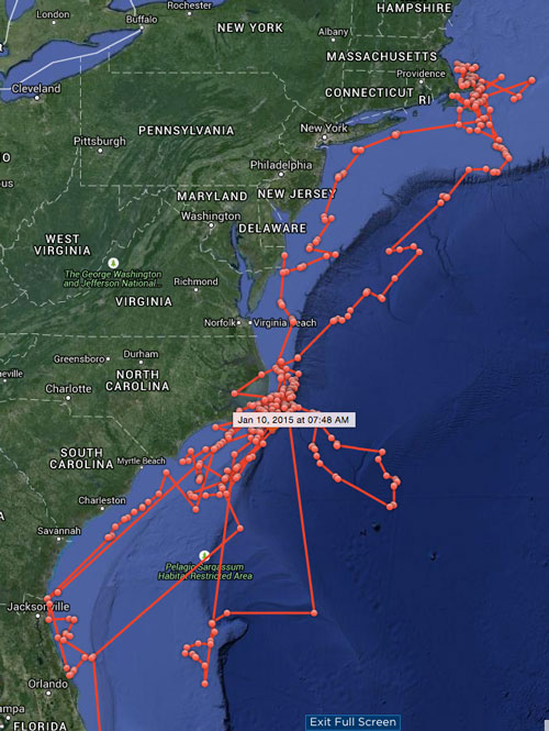
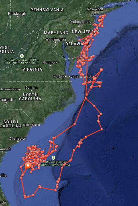
Now about those sharks. In case you were wondering whether Katharine or Mary Lee might have been culpable in the seven shark bitings off North Carolina during May and June — they were not. The maps here and their GPS timelogs give both solid alibis for all the attacks in question.
Katharine’s cruising over the past year.Mary Lee’s meandering over same time.
Part 1 of this column appeared in the June Survey Scene newsletter.
Basic Procedures for Establishing Accurate GNSS-Derived Ellipsoid Heights
David B. Zilkoski
In my first newsletter column of this series, Part 1, I discussed the basic concepts of GNSS-derived heights. My article discussed the three types of heights involved in determining GNSS-derived orthometric heights: ellipsoid, geoid, and orthometric. I also mentioned that each of these heights has its own error sources that need to be detected, reduced or eliminated by following specific procedures or applying special models.
GNSS-derived ellipsoid heights are the basis for GNSS-derived orthometric heights, so it makes sense to make these ellipsoid heights as close to error free as possible. This article will discuss guidelines for detecting, reducing and eliminating error sources in ellipsoid heights. It will focus on guidelines for establishing accurate ellipsoid heights in a local geodetic network.
Based on the Federal Geographic Data Committee publication “Geospatial Positioning Accuracy Standards, Part 2: Standards for Geodetic Networks,” guidelines were developed by the National Geodetic Survey (NGS) for performing GNSS surveys that are intended to achieve ellipsoid height network accuracies of 5 cm at the 95 percent confidence level, as well asellipsoid height local accuracies of 2 cm and 5 cm, also at the 95 percent confidence level. These guidelines were developed in partnership with federal, state and local government agencies, academia and private surveyors, and are the result of processing various test data sets and having extensive discussions with various GNSS users groups. These guidelines, known as NGS 58, have been documented in a publication titled “Guidelines for Establishing GPS-derived Ellipsoid Heights (Standards: 2 cm 9and 5 cm), Version 4.3″ and can be downloaded from the NGS website. NGS is reevaluating the guidelines and, based on its research results, will update the document appropriately (NGS, Personnel Communication).
Guidelines have also been written to establish GNSS-derived orthometric heights that approach these same accuracies, 2 cm and 5 cm. The slight differences between the accuracies of GNSS-derived ellipsoid heights and GNSS-derived orthometric heights will be generally due to the accuracy of the geoid model and published orthometric heights used to evaluate the differences between the three height systems: ellipsoid, geoid and orthometric heights. The topic “procedures for estimating accurate GNSS-derived orthometric heights” will be addressed in a future newsletter in this series.
If users follow the NGS guidelines, they will reduce or eliminate errors in ellipsoid height or, at a minimum, they will detect problems or errors in data. If these problems or errors are detected and corrected before the project is completed, then they will not be problems to the end users.
Basic Procedures for Detecting, Reducing, and Eliminating Errors in GNSS Ellipsoid Heights
The basic concepts listed below are very simple, but they all need to be followed as prescribed.
First and probably one of the most important procedure is to repeat baselines on different days and at different times of the day. This helps to detect and reduce the effects of: multipath, differences in height values due to different satellite geometry, and the amount of time a user must occupy a station for a short baseline, for instance, 30 minutes of good, valid data over baselines less than 10 km. (Although, it should be noted that to obtain 30 minutes of good, valid data, the user may have to obtain 45 to 60 minutes of data.)
The observing scheme for all stations requires that all adjacent stations (base lines) be observed at least twice on two different days and at two different times of the day. The purpose is to ensure different atmospheric conditions (different days) and significantly different satellite geometry (different times) for the two baseline measurements.
Keep baseline lengths under 10 km. The closer the two stations are, the better chance that common errors will cancel or nearly cancel, such as unmodeled atmospheric errors. It helps to reduce the amount of time the user must occupy a station in order to collect enough good, valid data to correctly fix all the integers.
Use fixed height poles. This helps eliminate errors due to incorrectly measuring the height of the antenna above the mark. Of course, when listening to GNSS users, nobody has ever measured the height of the tripod wrong. But, it’s strange how that turns out to be the most common error when fixed-height poles are not used.
Antenna set-up is critical. Plumbing bubbles on the antenna pole of the fixed-height tripod must be shaded when plumbing is performed. Plumbing bubbles must be shaded for at least 3 minutes before checking and/or re-plumbing. The perpendicularity of the poles must be checked at the beginning of the project and any other time there is suspicion of a problem. The user should also ensure the antenna is properly seated in the mount.
Use a geodetic antenna with ground plane and/or choke ring. This helps reduce effects of local multipath.
Final processing shall consist of fixing all integers for each vector for all sessions except to some control sites. Users should be able to fix the integers over baselines that are less than 10 kilometers. If the integers cannot be fixed, there is probably something wrong with the data, such as bad multipath effects, missing data due to blockage, or interference. Baseline solutions with fixed integers prove to be more reliable, consistent and accurate.
Simultaneously observe baselines between neighboring stations. This helps to ensure that closely spaced stations (neighboring stations) will have the desired local accuracy and are the stations that most users will want to use to validate their classical leveling results.
Establish a high-accuracy 3-D fiducial network that encompasses the entire project. This network helps to detect and reduce the effects of remaining systematic errors in the local network observations. This also ensures that when two local networks are eventually connected, they will be consistent with each other. This is a very important aspect of establishing accurate GNSS-derived ellipsoid heights using the guidelines documented in NGS 58. The survey should be referenced to at least three existing Continuous Operating Reference Stations (CORS) [NOAA CORS or equivalent] near the project area. The survey should also consist of at least three control stations that are referenced to the three CORS and interspersed throughout the project. For these control stations, receivers should collect data continuously and simultaneously for at least three, 5-hour sessions on three different days at different times of the day during the project. As previously stated, NGS is reevaluating the guidelines and will update them based on the results of their research. Until NGS updates the guidelines, the user should continue to collect long data sets at these control stations, because they are extremely important to detecting potential errors in the stations established using short data observing sessions.
Evaluating the Quality of Published NAD 83 (2011) Ellipsoid Heights
A description of the National Adjustment of 2011 Project (Alignment of passive control with the latest realization of the North American Datum of 1983: NAD 83(2011/PA11/MA11) epoch 2010.00) is available online.
I’ve listed a few paragraphs (and highlighted a few statements) from the write-up that I believe are important to anyone using published NAD 83 (2011) ellipsoid heights as control stations.
As part of continuing efforts to improve the NSRS, on June 30, 2012, NGS completed the National Adjustment of 2011 Project. This project was a nationwide adjustment of NGS “passive” control (physical marks that can be occupied with survey equipment, such as brass disk bench marks) positioned using GNSS technology. The adjustment was constrained to current North American Datum of 1983 (NAD 83) latitude, longitude and ellipsoid heights of NGS Continuously Operating Reference Stations (CORS). The CORS network is an “active” control system consisting of permanently mounted GNSS antennas, and it is the geometric foundation of the NSRS. Constraining the adjustment to the CORS optimally aligned the GNSS passive control with the active control, providing a unified reference frame to serve the nation’s geometric positioning needs.
For the final constrained adjustments, the median network accuracy for all stations was 0.9 cm horizontal and 1.5 cm vertical (i.e., ellipsoid height) at the 95% confidence level. The median change in coordinates from the previous published values was about 2 cm horizontally and vertically. However, some station coordinates changed by more than 1 meter horizontally and 60 cm vertically. Although some of the large coordinate changes resulted from new data and adjustment strategies, most horizontal changes greater than about 6 cm occurred in geologically active areas and were likely due to tectonic motion.
Results of the 2011 national adjustment for 79,677 passive control marks are available on NGS Datasheets, including their network and local accuracies.Of these passive marks, 79,161 are referenced to the North America tectonic plate as the 2011 realization (including CONUS, Alaska and the Caribbean); 345 are referenced to the Pacific plate as the PA11 realization (the central Pacific, including Hawaii, American Samoa and the Marshall Islands); and 171 are referenced to the Mariana plate as the MA11 realization (the western Pacific, including Guam, Palau and the Commonwealth of the Northern Mariana Islands). Although the passive marks are referenced to three different tectonic plates, all refer to a common 2010.0 epoch date. With the completion of the national adjustment, all passive marks on NGS Datasheets with NAD 83(2011/PA11/MA11) epoch 2010.00 coordinates will be consistent with results obtained using CORS and the NGS Online Positioning User Service (OPUS). Note that 183 stations were excluded from the final national adjustments due to lack of enabled vector connections; where possible, these stations will be reconnected to the network in subsequent individual adjustments.
Other technical issues addressed in the project include:
1. appropriate down-weighting of the up component of GNSS vectors to account for subsidence in the northern Gulf Coast region of CONUS;
2. use of variable weighted (stochastic) constraints for CORS based on formal accuracy estimates derived from the NGS MYCS1;
3. scaling of GNSS vector error estimates for all projects to ensure consistent weighting of observations;
4. use of down-weighting (rather than removal) for vector rejections;
5. splitting the conterminous U.S. into a Primary and Secondary network, as mentioned above, such that vectors observed prior to about 1994 were assigned to the Secondary network. This allowed the Primary network to be adjusted separately without the problems associated with older observations (e.g., single frequency receivers, no antenna phase center models, poor orbit accuracy, incomplete satellite constellation, lack of CORS, etc.).
Each of these technical challenges (and others) was satisfactorily resolved, and completion of the National Adjustment of 2011 Project represents a significant step toward a more integrated, consistent, and accurate NSRS.
First, I’d like to commend NGS for performing the NAD 83 (2011) national adjustment; it was a great accomplishment by NGS. It provides users with a consistent, accurate set of geodetic coordinates (latitude, longitude and ellipsoid height) that should serve the nation’s positioning requirements for many years. Saying that, there are some issues that the user needs to consider when using published NAD 83 (2011) ellipsoid heights as constraints in GNSS network adjustments:
Generally, the NAD 83 (2011) network design was sufficient for determining accurate horizontal coordinates (latitude and longitude) but may not have been sufficient for establishing the vertical component (ellipsoid height) accurate enough for use as control stations in NGS Height Modernization Projects (see this webpage for more information on NGS’ Height Modernization Program) . Many of the earlier GNSS projects, prior to the publication of NGS 58, did not repeat baselines; stations were, however, usually occupied at least twice and observing sessions lasted for two hours or more. They were generally evaluated using loop closures and adjustment statistics, but loop analysis and adjustments do not always detect, reduce and/or eliminate all problems.
In addition, prior to NGS 58, not all closely spaced stations (neighboring stations) were simultaneously observed during the same session. In my opinion, the published formal errors may be too optimistic for some of these stations. These stations may be very precise but based on the survey field procedures performed prior to the publication of NGS 58, it is my opinion that the relative ellipsoid height accuracy for closely-spaced stations that were not simultaneously observed during the same session may not be as accurate as their listed median accuracy value.
Stations that were observed following the NGS 58 document are labeled as Height Modernization stations on the NGS datasheet and their ellipsoid height values should be good to the 2-cm level if they were involved in the same project.
It is important to understand the quality of published NAD 83 (2011) ellipsoid heights because your project’s GNSS-derived ellipsoid height values will be evaluated by them. The project’s control stations help to detect and reduce the effects of remaining systematic errors in the local network so they need to be very accurately determined.
Identifying good, valid published NAD 83 (2011) ellipsoid heights accurate enough to evaluate the results of a GNSS project isn’t an exact science, but there are ways to identify good candidates. I’ve listed three ways of using NGS published datasheets to help the user evaluate the quality of NAD 83 (2011) ellipsoid heights.
Identify stations that were established in Height Modernization Projects (that is, the stations were established following NGS 58 guidelines).
Analyze the network and local accuracy values to identify stations with accuracy values less than 2 cm.
Use local accuracy tables of stations to determine if closely spaced monuments (neighboring stations) were occupied during the same session.
The user can retrieve NGS datasheets in text form or as a shape file using NGS’ Datasheet retrieval program. Identifying stations involved in a NGS Height Modernization Project is simple because the datasheet adds a note stating that a particular station is a Height Modernization Survey Station. The user can assume these stations were determined following NGS 58 guidelines. An example of a station involved in a height modernization project is station CARGO, DJ5933 (see the datasheet below). The NGS datasheet also lists the station’s network and local accuracies. On the datasheet, the network accuracy value is listed below the coordinates (for instance, 1.39 cm for station CARGO). Below the network accuracy value, the user can obtain the local accuracy values by clicking on the following link in the datasheet: “Click here for local accuracies and other accuracy information.” You can obtain the full NGS datasheet for CARGO.
The NGS Data Sheet for Height Modernization Station CARGO (DJ5933) PROGRAM = datasheet95, VERSION = 8.71 National Geodetic Survey, Retrieval Date = JULY 12, 2015 DJ5933*********************************************************************** DJ5933 HT_MOD – This is a Height Modernization Survey Station. DJ5933 DESIGNATION – CARGO DJ5933 PID – DJ5933DJ5933 STATE/COUNTY- NC/NEW HANOVERDJ5933 COUNTRY – US DJ5933 USGS QUAD – WILMINGTON (1979)DJ5933DJ5933 *CURRENT SURVEY CONTROL DJ5933 ______________________________________________________________________ DJ5933* NAD 83(2011) POSITION- 34 12 27.89075(N) 077 57 16.40009(W) ADJUSTED DJ5933* NAD 83(2011) ELLIP HT- -34.732 (meters) (06/27/12) ADJUSTED DJ5933* NAD 83(2011) EPOCH – 2010.00 DJ5933* NAVD 88 ORTHO HEIGHT – 2.05 (meters) 6.7 (feet) GPS OBS DJ5933 ______________________________________________________________________ DJ5933 NAVD 88 orthometric height was determined with geoid model GEOID03 DJ5933 GEOID HEIGHT – -36.78 (meters) GEOID03DJ5933 GEOID HEIGHT – -36.80 (meters) GEOID12BDJ5933 NAD 83(2011) X – 1,101,934.174 (meters) COMPDJ5933 NAD 83(2011) Y – -5,164,049.037 (meters) COMPDJ5933 NAD 83(2011) Z – 3,565,508.167 (meters) COMPDJ5933 LAPLACE CORR – -5.30 (seconds) DEFLEC12B
DJ5933
DJ5933 Network accuracy estimates per FGDC Geospatial Positioning Accuracy
DJ5933 Standards:
DJ5933 FGDC (95% conf, cm) Standard deviation (cm) CorrNE
DJ5933 Click here for local accuracies and other accuracy information.
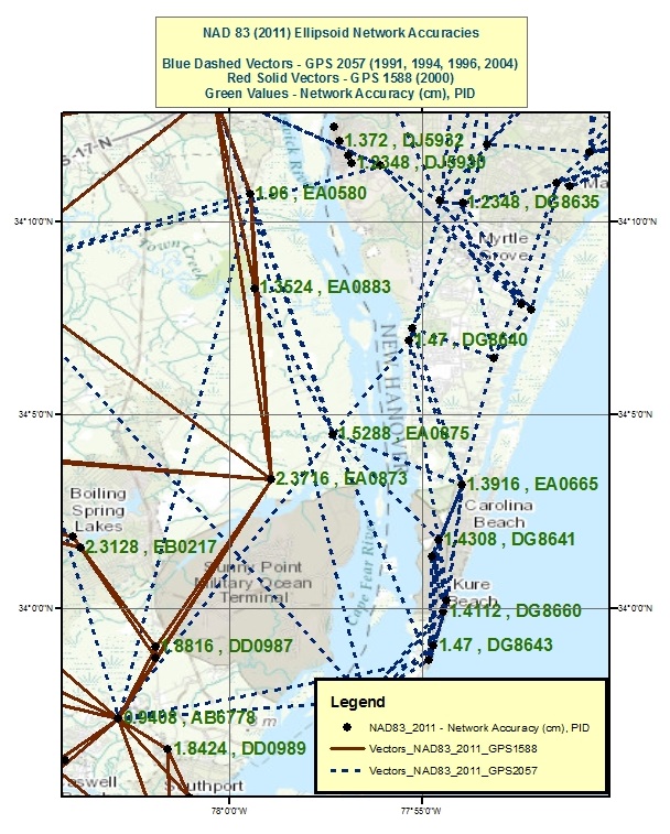
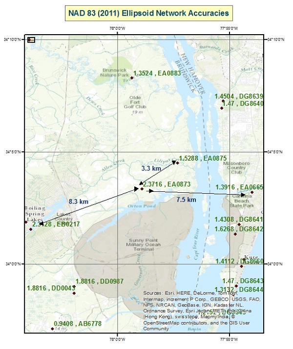
Local accuracies provided on the NGS datasheet can be used to determine if closely spaced stations were simultaneously observed during the same session. If two stations were simultaneously observed during the same session, they will have a local accuracy value listed in their table. Station TOWN CREEK (EA0883) is an example of a station that was simultaneously observed by BR 7 (EA0873) in one GNSS project and by LILIPUT (EA0875) in a different project. (Figure 1 depicts these stations and their NAD 83 (2011) network accuracy values.) Looking at the highlighted section of the tables below, station EA0883 is listed in the local accuracy tables for EA0873 and EA0875, so it was simultaneously observed during sessions with EA0873 and EA0875.
Saying that, we can also use the tables to show that EA0873 and EA0875 were not simultaneously observed during the same session. That is, EA0873 is not listed on EA0875 local accuracy table and EA0875 is not listed on EA0873 local accuracy table so they were not processed simultaneous in a session. Figure 2 depicts the two GNSS projects that include observations involving stations EA0873 and EA0875. The user can perform the same procedure to determine that stations EB0217 and EA0873, 8.3 km apart, were not simultaneously observed during the same session, and similarly EA0873 and EA0665, 7.5 km apart, were not simultaneously observed during the same project. Please note I am not suggesting that anything is wrong with these surveys; there may be good reasons why these stations were not simultaneously observed during the same project. I am only using it as an example in this column. Network and local accuracy values are good indicators of potentially “how good” a station is relative to its neighbor, but they should always be evaluated and investigated. My intent is to provide the user with tools for evaluating the quality of published NAD 83 (2011) ellipsoid heights. This is important because published coordinates are used to evaluate the adjustment results of new projects.
Local and Network Accuracy Data for NGS Datasheet – EA0873 Program lna_ret Version 2.7 Date April 6, 2015 National Geodetic Survey, Retrieval Date = JUNE 30, 2015 EA0873 ************************************************************ EA0873 ACCURACIES – Complete network and local accuracy information. EA0873 DESIGNATION – BR 7 EA0873 PID – EA0873 EA0873 EA0873 Horiz and Ellip are the horizontal and ellipsoid height accuracies EA0873 at the 95% confidence level per Federal Geographic Data Committee EA0873 Geospatial Positioning Accuracy Standards. SD_N, SD_E and SD_h are EA0873 the standard deviations (one sigma) of the coordinates (NETWORK) or EA0873 of the difference in the coordinates (LOCAL) in latitude, longitude EA0873 and ellipsoid height. CorrNE is the (unitless) correlation EA0873 coefficient between the latitude and longitude components of either EA0873 the coordinate (NETWORK) or coordinate difference (LOCAL). Dist is EA0873 the three-dimensional straight-line slope distance, in km, between EA0873 station EA0873 and the corresponding local station. Local stations EA0873 are stations processed simultaneously in a session regardless of EA0873 distance. EA0873EA0873 Accuracy and standard deviation values are given in cm.EA0873EA0873 Type/PID Horiz Ellip Dist(km) SD_N SD_E SD_h CorrNEEA0873 ——————————————————————-
Local and Network Accuracy Data for NGS Datasheets – EA0875 Program lna_ret Version 2.7 Date April 6, 2015National Geodetic Survey, Retrieval Date = JUNE 30, 2015 EA0875 ********************************************************** EA0875 ACCURACIES – Complete network and local accuracy information. EA0875 DESIGNATION – LILIPUT EA0875 PID – EA0875 EA0875 EA0875 Horiz and Ellip are the horizontal and ellipsoid height accuracies EA0875 at the 95% confidence level per Federal Geographic Data Committee EA0875 Geospatial Positioning Accuracy Standards. SD_N, SD_E and SD_h are EA0875 the standard deviations (one sigma) of the coordinates (NETWORK) or EA0875 of the difference in the coordinates (LOCAL) in latitude, longitude EA0875 and ellipsoid height. CorrNE is the (unitless) correlation EA0875 coefficient between the latitude and longitude components of either EA0875 the coordinate (NETWORK) or coordinate difference (LOCAL). Dist is EA0875 the three-dimensional straight-line slope distance, in km, between EA0875 station EA0875 and the corresponding local station. Local stations EA0875 are stations processed simultaneously in a session regardless ofEA0875 distance.EA0875EA0875 Accuracy and standard deviation values are given in cm.EA0875EA0875 Type/PID Horiz Ellip Dist(km) SD_N SD_E SD_h CorrNE
I haven’t discussed all procedures documented in NGS 58 here. There are other minor, but very important, procedures that the user must follow, such as use of precise ephemerides, taking a rubbing of the mark; the reader is referred to NOAA Technical Memorandum NOS NGS-58, “Guidelines for Establishing GPS-derived Ellipsoid Heights (Standards: 2 cm and 5 cm), Version 4.3,” for more details.
This column discussed procedures that need to be followed to detect, reduce and eliminate error sources to estimate accurate GNSS-derived ellipsoid heights. Analysis of the quality of project data should be based on repeatability of measurements, adjustment residuals and analysis of loop closures. Please be aware that repeatability and loop closures do not always disclose all problems, and that is why it is important to adhere to the procedures outlined in NGS’ publications.
It is important to understand geoid models when estimating GNSS-derived orthometric heights. The user should understand the differences between NGS’ scientific gravimetric geoid model and hybrid geoid models, and why it is important to use both types of geoid models in an analysis. As I mentioned in Part 1, the latest NGS hybrid geoid model, Geoid12B, is made consistent with the published NAVD 88 heights. This means you will be consistent with NAVD 88 when using GEOID12B to estimate GNSS-derived orthometric heights. However, this doesn’t guarantee that your GNSS-derived orthometric heights are accurate. NGS’ new Beta experimental geoid height model xGEOID14B is not distorted to fit the published NAVD 88 heights so it is useful for identifying valid NAVD 88 benchmarks. In my next column, I’ll address how to use these geoid models and published NAD 83 (2011) ellipsoid heights to evaluate potential issues with published NAVD 88 heights.
Figure 1. NAD 83 (2011) Ellipsoid Network Accuracies – units cm (Network accuracies were obtained from NGS datasheets).Figure 2. NAD 83 (2011) Network Design for Stations EA0873 and EA0875. [Note: GNSS Vectors for GNSS projects GPS 1588 and GPS 2057 were provided by NGS].
Last week, Esri held its 36th International User Conference in San Diego. With 15,000+ attendees from 130 countries, it is the largest gathering of geospatial professionals in North America.
The general plenary presentation on Monday morning is always an interesting event. Founder Jack Dangermond leads the plenary and presents his vision for the year, and years, to come. Here’s the opening Plenary video (3 minutes):
The message of this year’s Plenary was “Applying Geography Everywhere” with the central theme was Web GIS. Here is a video of Mr. Dangermond’s GIS vision (12:42 minutes):
For the past few years, he’s spoken quite a bit about the democratization of geography by making GIS capability available to an audience other than the GIS professional by expanding its impact across an organization at many levels. Here’s a slide he’s presented in the past, and I think it’s consistent with where he sees GIS heading; a global awareness and global usage of GIS apps and data.
Esri thinks that Web GIS is an enabling technology that will be a catalyst for the democratization of GIS across all of an organization’s departments.
How GIS has evolved. (Credit: Eric Gakstatter)
During the Plenary, Bern Szukalski outlined Esri’s take on the current trends in Web GIS:
Portals. The windows into GIS. Thousands of public and private portals serve up GIS data and services.
Content. A collection of authoritative and curated content that Esri calls a living atlas, with some data being updated daily or even hourly.
Analysis tools. For the non-GIS professional to answer simple (or complex) queries such as emergency services coverage in a particular municipality, leveraging the living atlas content to use the most up-to-date data.
Smart mapping. New data-driven web cartography functionality and data exploration that leverages the right tools presented at the right time. Think of it like Google search that shows you relevant web sites based on your past web surfing.
Story maps. A combination of Web GIS and rich media to tell a compelling story. A new and unreleased type of Story map presented by Bern is the Story map Cascade, an immersive experience as you advance through the story and interact with map, amplifying the value of GIS.
If you want to view Bern’s plenary presentation on Web GIS trends, see the following 9-minute video:
Esri Product Roadmap
I get the feeling that ArcGIS Pro will be Esri’s premiere desktop product. When you buy ArcGIS, in addition to ArcMap, you also get a concurrent license for ArcGIS Pro (and ArcGIS Online), and you can see from the following slide that ArcGIS Pro incremental upgrades follow ArcMap. The following slide also shows the timing for the ArcGIS 10.4 release.
Another product Esri is going to release later this year to further promote the democratization of digital geography is a product called ArcGIS Earth. Just by the name, you can imagine the type of product it’s going to be. It’s all about 3D visualization.
Lastly, many of you may have missed the discussion about a new Esri Mobile GIS app called Survey123. There wasn’t a big announcement made, but it seems to be a powerful little app. For those of you who think Collector is a bit too structured, Survey123 might be the app for you. You can easily author smart forms following the XLSForm specification and quickly set up data-collection workflows. This is a really neat feature of Survey123, because you can create your mobile GIS data-collection pick lists and use form logic in an Excel spreadsheet instead of having to create it in the Esri environment.
It might end up being my favorite Esri mobile GIS app. But, you’ll have to wait to give it a spin because it’s not slated for release until later this year.
In other mobile GIS news at the conference, it appears as though Microsoft is concerned about Android and iOS dominating the mobile device space, so much so that Microsoft co-founder Bill Gates made a recorded presentation at the plenary. Even more interesting is that Mr. Dangermond suggested that perhaps Mr. Gates might make a live appearance at the Esri UC sometime in the future.
Bill Gates delivers an address to the Esri plenary audience. (Photo: Eric Gakstatter)
On the technical side of Microsoft, it looks like the end is in sight for the separate software development platforms for Windows Desktop and Windows Phone. With Windows 10, I heard that the software development environment for Windows Desktop and Windows Phone (or whatever it’s going to be called) is going to be the same, so you should start seeing Windows devices pick up some momentum next year.
The value of accurate maps is not lost on the automotive industry as it transitions from connected cars to automated vehicles. Three German automakers are rumored to be making a multibillion-dollar investment in Nokia’s HERE mapping division. If the deal goes through as expected by late July, Nokia, which purchased HERE (then called Navteq) for $8 billion in 2007, will have spurned several deep-pocket suitors.
Although not officially confirmed, Nokia’s HERE digital mapping service is set to be purchased by a German auto consortium of Daimler, BMW and Volkswagen’s Audi unit, according to published sources.
Estimates of the deal place it in the $2.7 billion to more than $3 billion range. The potential sale puts to rest industry concern that Google or another giant non-automotive entity would make the winning bid for a company with increasing importance to connected and autonomous vehicles.
Either way, it’s too early to analyze what exactly are the consequences if the German consortium closes the deal with Nokia, said Thilo Koslowski, Gartner vice president and analyst. “In order to justify the purchase price of the acquisition, it will be in the interest of any acquiring party to keep Nokia HERE’s future role as neutral as possible in order not to alienate other clients,” he said. “I could imagine that contractually the acquiring party might be tied to serving these other clients for a least a certain time. If that doesn’t happen, and the deal would be ‘exclusive,’ then it would certainly boost the appeal of other map data providers and encourage new players to emerge.”
If the deal goes through, the German consortium plans to invite such other automotive companies as Fiat Chrysler, Ford, Renault, Toyota and General Motors, according to the Wall Street Journal.
Another take on the potential agreement could be whether car companies have to weigh the pluses and minuses of to join the consortium — or map competitor TomTom needs to consider whether it has more to gain from remaining independent or creating its own consortium, said Roger Lanctot, strategy analytics associate director, global automotive practice.
Industry old-timers may remember the bitter rivalry between Navteq (formerly Navigation Technologies) and Tele Atlas (formerly Etak). This rivalry has remained, even though the names have changed and the location industry has evolved dramatically since 2007, when both Navteq and Tele Atlas were bought by Nokia and TomTom, respectively, in multibillion-dollar deals.
The bidding war for HERE began in April, when Nokia purchased Alcatel Lucent to transition from the location industry. In addition to the German auto consortium, Uber and Chinese technology provider Baidu, Google and Apple were said to be potential buyers. However, Google’s purchase of HERE would have been disruptive to the auto industry, Lanctot wrote in a LinkedIn column. “Google buying HERE would drive the entire industry into the arms of TomTom while removing the leverage-ability of a map duopoly. Google buying both TomTom and HERE would annihilate billions of dollars in research and development activity by car makers seeking to create a truly driver-oriented browsing experience intended to enhance safety,” he wrote.
Mike Dobson, TeleMapics president, who writes about digital maps at www.telemapics.com, recently said that Uber was playing with fire by bidding on HERE because they were clearly concerned about autonomous vehicles. “Within 10 years, Uber will be producing its own fleet of [autonomous vehicles]. While owning a map company might be beneficial to them, they might be better off licensing map databases,” he said.
Uber, which bought mapping company deCarta and Microsoft’s Bing Maps, ultimately withdrew from the bidding war for Here.
City Built for Autonomous Testing Unveiled in Michigan
A 32-acre simulated city recently opened to test how self-diving cars will perform in the future. The $10 million facility, called Mcity and located on the north campus of the University of Michigan, was created by the school’s Mobility Transformation Center and the Transportation Research Institute.
With all the bells and whistles — a bridge, a tunnel, traffic circle, etc. — the facility will rival anything existing, if it hasn’t already surpassed it, in Silicon Valley or Pittsburgh, which seem to be the centers of gravity for the nascent autonomous vehicle industry.
Mcity, which was a government-industry partnership, plans to “lay the foundations for a commercially viable ecosystem of connected and automated mobility,” said a university press release. [Editor’s note: It is refreshing to see the “commercially viable” thrown in there by an academic institution.]
Another key goal is to implement a connected and automated mobility system on the streets of southeastern Michigan by 2021. The MTC is developing deployments of more than 20,000 cars, trucks and buses across southeastern Michigan, serving as testbeds for evaluating consumer behavior and exploring market opportunities, the university said.
At the same time as the Mcity announcement, also in Ann Arbor, the Automated Vehicle Symposium, which is the largest autonomous vehicle conference, was being held at a local hotel. While the conference had such keynote speakers as Google’s Chris Urmson, and sponsors that included Denso and Uber, it still has the feel of this government/academic/technical conference — not unlike TRB or ITS America.
In fact, like many government meetings, the afternoon “breakout sessions” were closed off to the press. This leads to the question, with so many new, and expensive, autonomous vehicle conferences springing up, why isn’t there a single panel on the future worldwide market opportunity?
In other location news:
IndoorAtlas signed a $3 million deal with South Korea’s SK Planet, a subsidiary of SK Telecom, to target the e-commerce market. IndoorAtlas’ investors include ST Planet and Chinese technology provider Baidu, which made a $10 million investment in the company.
Nokia’s HERE mapping and location services business is developing a new global standard for contactless transport ticketing payments using Near Field Communications-enabled mobile phones. HERE announced the formation of the Open Mobile Ticketing Alliance, or OMTA, to help consumers purchase public transit ticket using a mobile app.
HERE competitor TomTom continues to be a major force in vehicle monitoring and location, recently announcing its telematics division broke 500,000 subscribers. Overall, the company serve 36,000 customers, primarily in the European fleet market.
Not everyone wants to be located. Consumers think they have the ability to turn off the tracking ability of their phones. But can they? More about that later. In other news, there are good reasons why Nokia’s HERE mapping is still on the selling block. And blind people are using a no-tech version of a widely used location positioning method that doesn’t need canes.
The controls that phone makers have devised to enable consumers to opt out of being located have a big hole. Android-based phones are giving app makers free access to phone data that can be used to surreptitiously geolocate devices. The data comes from an unlikely source: power consumption, and no consent is needed.
The technique, called PowerSpy, was developed by researchers at Stanford and Rafael, Israel’s defense research group, and gathers a phone’s power usage history. Simplistically, the location of the phone is tracked by using the phone’s battery consumption to determine the distance of a phone to a cell tower. The further the distance, or the greater the obstacles blocking the tower, the more power is consumed by the battery. The researchers say they can take into account phone usage battery drain and filter out the noise created by focusing on long-term trends.
At its current level of development, the PowerSpy method requires the snoop to have driven a route (war driving) to identify its power consumption pattern. With tests conducted in San Francisco, the method worked with 90 percent accuracy to identify a correct route from seven choices. The team is working on using the data to detect unknown routes that have not been previewed.
How would the hypothetical stalker, crook or unethical mobile advertiser get access to this data? They would entice a person to download an app. The smoke screen app might be a game or a productivity app that is quietly slurping up the power consumption data.
Here Today, Not Gone Tomorrow? Wouldn’t you think that Nokia would by now have clinched a deal to sell the mapping division? Given its mapping debacle, Apple was on the top of everyone’s list as a buyer, but apparently the company didn’t even participate in the bidding, and instead is committed to further development of its self-built mapping database. Contenders — Facebook, Baidu, Tencent and Uber — seem to have dropped out of the competition. Left is a consortium of German automakers — BMW, Daimler and Volkswagen — who feel that they should get a better deal with no other buyers in sight. It is a double-edged sword, as they also worry that if the highly accurate maps are acquired by tech firms, the car makers will lose a competitive advantage in the fight for supremacy of the automated vehicle. High-precision mapping is critical to the success of the auto OEMs.
Who Will Win Connected Vehicles? Follow the Money. Investors who want a piece of the connected vehicle action are placing bets on the tech companies, not the auto OEMs. Many blue chip and small companies are seeing healthy gains in price. Sensor chip makers, car infotainment and telecom companies are some of the winners. With the surge of connectivity required in the Internet of Things, networking technology will also do well.
E911 Innovations. While regulations are in place for eventually requiring technology to automatically identify the location of indoor E911 calls, dispatchers don’t yet have that capability. Callers can be inside a large complex, like a dormitory or hotel, and if they are unable to speak or identify their location, response is hampered. Smart911 from Rave Mobile Safety is sending dispatchers floor plans of buildings to help in rescue efforts. The maps are automatically sent with the 911 call and have already been credited with quicker responses.
Quick Business News. Uber acquired Microsoft’s geo-imagery team and assets, known at BIT (Bing Imagery Technologies), which is based in Boulder. Microsoft didn’t need this technology as it had already outsourced Bing Maps technology to Nokia HERE. Telecommunication Systems (TCS) purchased location-based technology and intellectual property from Loctronix. The purchase will further TCS in developing indoor-location technologies. Denmark has become the first country to use real-time traffic data across a national network. Denmark will use GPS probe data managed by INRIX for congestion management. The Internet of Things relies on multitudes of sensors and a new start-up, Sense360, has built a platform to manage that data.
No-Tech Location Technology. Daniel Kish was a particularly helpful kid who made deliveries for his mom to homes outside of his neighborhood. What is unusual is that Kish is blind and uses echolocation to “see” the space around him. He clicks his tongue to ascertain the unique echoes of his surroundings, starting by identifying areas of high or low density, such as tall buildings, squat houses or open space. And in a version of drive testing, blind users like Kish first walk a neighborhood with a sighted guide and remember the signature echoes. Whether it is solely by ear or with a big computer algorithm like PowerSpy, pattern mapping can be effective.
Half of the GPS constellation now transmits the new civil signal, L2C. In a matter of weeks, that number will crest into the majority of the constellation when IIF-10 is set active and operational to users. By the end of the year or early 2016, look for 18 usable satellites transmitting L2C. That could be considered a nominal initial operating capability (IOC), though it is unlikely to be declared as such by the Air Force. We can anticipate a full operating capability (FOC) within five years. Many high-precision GPS receivers currently embody L2C signal processing capability.
As Oscar Colombo, research scientist at NASA, noted in a recent CANSPACE contributed note, “This seems like a moment to start seriously thinking about using L2C as much as possible.”
This month’s newsletter presents an amalgam, a panel discussion in virtual print, on several aspects and viewpoints stimulated by his posting,
Some readers may want to peruse this U.S. government bulletin for a general description of L2C; others who feel sufficiently informed may skip directly two paragraphs down to “Three issues might be in the way of that being a practical proposition.”
“L2C is the second civilian GPS signal, designed specifically to meet commercial needs. Its name refers to the radio frequency used by the signal (1227 MHz, or L2) and the fact that it is for civilian use. There are also two military signals at the L2 frequency. When combined with L1 C/A in a dual-frequency receiver, L2C enables ionospheric correction, a technique that boosts accuracy. Civilians with dual-frequency GPS receivers enjoy the same accuracy as the military (or better). For professional users with existing dual-frequency operations, L2C delivers faster signal acquisition, enhanced reliability, and greater operating range. L2C broadcasts at a higher effective power than the legacy L1 C/A signal, making it easier to receive under trees and even indoors. The Commerce Department estimates L2C could generate $5.8 billion in economic productivity benefits through the year 2030. The first GPS IIR(M) satellite featuring L2C launched in 2005. Every GPS satellite fielded since then has included an L2C transmitter.”
Oscar Colombo’s CANSPACE note continues:
“Three issues might be in the way of that [using L2C as much as possible] being a practical proposition, and I would appreciate comments on some or all of them:
“(1) The fact that the new L2C navigation code (CNAV) is being transmitted, but flagged as pre-operational by the USAF, indicating that this organization is not yet ready to guarantee its fitness for use.
“(2) The quarter-wave phase difference with the heritage signal L2.
This one is important to know when fixing the ambiguities of differential observations (double differences and first order differences between satellites) combining L2C data from IIR-M and IIF satellites with those with only L2 (IIR and IIA). Some high-end commercial receivers correct for this phase difference, some don’t. The latest RTCM document I’ve seen that touched on this issue came out in 2013 (RTCM Standard 10403.2, Paragraph 3.1.8, Table 3.1-5), and listed the choices , at that time, by nine leading manufacturers on this matter. The list does not include all of present-day manufacturers of high-end receivers, a list that changes over time.
“(3) There is no proper place for L2C in files in the widely used Rinex 2.11 format.
In principle, this can be taken care of by using data files in the Rinex 3 format. However, the use of Rinex 3, that has some major departures from 2.11, is not universal yet.
“Does anyone know of an up-to-date, reliable and comprehensive list of receiver manufacturers showing those that correct and those that do not correct for the quarter-wave phase shift?”
GPS World contributing editors Eric Gakstatter (Geospatial Solutions) and Don Jewell (Defense) had a private conversation about the above, which I now make public.
Don Jewell: “I can address this from a policy and operational perspective but you [Eric] have a better feel for the users perspective.
“With two more successful IIF launches there will then be 18 L2C SVs broadcasting that signal, and that is considered by the government to be nominal IOC, an initial operating capability. Regardless of where you are on the Earth, shy of 60 deg N and 60 deg S, you should always have at least one or more L2C SVs in view.
“We are probably looking at 2023 (8 more years) before the L2 carrier phase is in jeopardy of shifting without notice. If indeed that ever happens.
“So from an operational and providers (HQ AFSPC, 50SW and 2SOPS) perspective, certainly the L2C signal should be useful and reliable. Just not normally guaranteed until FOC or full operational capability is declared, usually with 24 SVs broadcasting L2C. With no premature losses that will be halfway through the GPS III launch schedule ~ 2019-20.
“Schedules are dynamic and always subject to change of course.”
[Editor’s note: The L2 carrier isn’t going to go away or shifting to another frequency. What might go away is the P(Y) modulation on the L2 carrier if the DoD considers the P(Y) signals redundant once the M-code is fully embraced. If the P(Y) signal on L2 is no longer transmitted, then civil receivers currently using the P(Y) signal to obtain L2 carrier-phase measurements will no longer be able to do this.]
Eric Gakstatter replied, “I’ve heard that some manufacturers say they are taking advantage of L2C when there are IIRM or IIFs in view and maybe some of the receivers I’m using are doing so. I’ve not paid attention to it.
“It could be helpful in areas where users are trying to work in difficult environments such as near and under tree canopy.
“In the case of RTK, I would think the reference station would have to broadcast L2C data.”
A CANSPACE reader provided the following useful reference, which although it dates from 2012, still contains much immutable data: “The most recent view on the situation I have with L2C can be found here.”
This links to the presentation slides from an American Geophysical Union 2012 Fall Meeting paper, “The Effects of L2C Signal Tracking on High-Precision Carrier Phase GPS Positioning: Implication for the Next Generation of GNSS Systems,” by Frederick Blume, Henry Beglund, and Lou Estey of UNAVCO, a non-profit university-governed consortium, facilitates geoscience research and education using geodesy.
Oscar Colombo and other CANSPACE subscribers have contributed several further notes t the L2C discussion string. To read them, it’s possible to access the archives here.
Or you can more simply and elegantly subscribe to CANSPACE; see instructions here.
Last month, Richard Langley and Oliver Montenbruck jointly communicated the following interesting aspect of the U.S. Federal Radionavigation Plan to CANSPACE readers:
“in the new version of the FRP is a new phrasing of the earlier statement on guaranteed availability of the P(Y) signal only up to 2020:
“The [U.S. Government (USG)] commits to maintaining the existing GPS L1 C/A, L1 P(Y), L2C, and L2 P(Y) signal characteristics that enable codeless and semi-codeless GPS access until at least two years after there are 24 operational satellites broadcasting L5. Barring a national security requirement, the USG does not intend to change these signal characteristics before then. Twenty-four satellites broadcasting the L5 signal is estimated to occur in 2024. This will allow for the orderly and systematic transition of users of semi-codeless and codeless receiving equipment to the use of equipment using modernized civil-coded signals. Note that it is expected that 24 operational satellites broadcasting L2C will be available by 2018, enabling transition to that signal at this earlier date. Civilian users of GPS are encouraged to start their planning for transition now.”
Finally, Richard Langley notes that “I have a student looking into which Precise Point Positioning engines can currently process L2C observables, but his report is not yet available. Also, we are looking into adding an optional L2C processing capability to the University of New Brunswick PPP software, GAPS (GPS Analysis and Positioning Software), but that’s a month or so away.”
By Denis Parrot Guest Columnist, Survey Scene newsletter
I recently read an article by David Doyle entitled “Why Doesn’t my Centimeter Match Your Centimeter?” (May Survey Scene), which painted an interesting portrait of the widespread use of GNSS-based data collection systems. Nowadays, almost everyone can claim to have surveys with centimeter or sub-meter accuracy anywhere in the world, which before was achievable only by a few rare specialists. In many cases, the positions do not always fall at the right place when they are integrated into geographical information systems (GIS). Unfortunately, it is often at this stage that we call on a specialist! The key is in the reference system, also known as datum.
Even if it can become relatively complex when it comes to details, the concept of a reference system when using the GNSS system is essentially identical to conventional surveying techniques. A surveyor always used a reference station for his survey using his theodolite. He stringently maintained his control point network on the territory being surveyed. All his surveys were in reference to his control network (points that are part of a series of controlled polygons). If certain polygons were not well linked to the rest of the network, integration with centimeter precision into the computer-assisted design program (or his geographical information system [GIS]) would be problematic, or even impossible, for the lots linked to the erroneous polygons. And this is exactly what happens with the GNSS system; if the reference is overlooked, GIS integration becomes a real problem.
Without realizing it, GNSS users also use a reference network. If they work in RTK (differential positioning), they use either a VRS (Virtual Reference System) or a station network that sends corrections. In general, these two systems are based on a national reference system (geocentric or not). Users can also use a portable base that they install themselves as needed. When they enter a coordinate into this portable station, they become responsible for the reference system used. During post-processing, the problem remains the same. A position must be entered for the base station and the reference must be known (i.e., the datum).
Example of positions that do not fall at the right place when they are integrated into a geographical information system (GIS).
If they use satellite-based augmentation systems (SBAS), such as the private Omnistar, Veripos or StarFire systems, these systems are generally referenced by a geocentric system (which nowadays includes a temporal drift) defined by international bodies (IGN in France, which maintains, along with several research centers, the International Terrestrial Reference Frame (ITRF)). Today, this method of positioning is known as PPP or precise point positioning.
These different GNSS positioning methods, therefore, do not use the same reference! Each may provide highly accurate coordinates. However, these coordinates are only accurate with regard to their reference. Although this concept may seem very simple, in reality the increasingly common use of these systems by non-specialists often produces strange results.
Below are a few examples of uses that may lead to confusion with reference systems, in terms of “compared with what?”:
A farmer who carries out micro-topography to analyze his fields is pleasantly surprised by the level of altimetric precision he can achieve (within a few cm), using a “single-frequency” receiver. However, when he tries to juxtapose two fields, he may discover an altimetric deviation of up to 2 meters. The reason for this is quite simple: he systematically used local base stations with average coordinates taken in the field as the base coordinates. Normally, he uses one base per field. By not taking into account the consistency of the coordinates for the base stations, without realizing it, this farmer was creating independent references for each of his fields. It is obvious that if the analysis had been done individually on each field, he would not have seen any problem. It is when the two juxtaposed fields are integrated that problems arise.
Photo courtesy of Effigis.
In Quebec, a surveyor uses a Department of Energy and Natural Resources station as a source for RTK differential corrections. This system is referenced to the NAD83 SCRS coordinates system. When he tries to integrate his survey points using the conventional method, which are based on the original NAD83 coordinates system, he will notice inconsistencies of a few to several centimeters. These two coordinate systems (NAD83 ≠ NAD83SCRS) may have inconsistencies of several centimeters from each other.
In Canada, an agronomist surveys the position of trees in the city using a portable GNSS system with an SBAS corrections system. Once the survey has been completed and he integrates the position of the trees into the city’s GIS, these all seem to be off by +/- 1.5 m. The SBAS reference systems are all geocentric (within +/- several cm) compared with the NAD83 SCRS system, which is positioned +/- 1.5 m from the Earth’s center!
These three examples illustrate the type of error commonly found in the “reference system” category. The issue here is not GNSS system performance, since we are assuming that the positions obtained are accurate versus the chosen reference. Neither does the issue concern the variations between different reference systems, or the methods or precision of transformations between one reference system and another (this topic is very broad).
Lastly, we should find the answer to the question “But compared with what?” in what we commonly call “metadata.” Regarding GNSS position, this is information related to creating positions: the reference system used, statistics regarding the position estimate, date, different dilution of precision (DOP) values, type of GNSS signal used, etc.
For your next delivery, simply mention “Precise, but compared with what?” or deliver your positions along with full metadata!
Denis Parrot earned a degree in surveying and mapping from Université Laval in 1981, and began his career working in those fields around the world for five years. He then completed graduate studies in Fredericton, New Brunswick, where he earned a master’s in satellite geodesy. With a passion for his area of expertise, Parrot has been involved since 1991 in a host of projects that employ geospatial information to meet the specific needs of various markets and users. He is currently president at Effigis and responsible for the OnPOZ Product division, including the commercial aspect and R&D activities.
This column originally appeared as a blog at the Effigis Geo Solutions website, and is shared with permission.
At Caltrans District 7 in Los Angeles, we use the onboard GPS capability of smartphones to navigate in real time to the locations of proposed aerial targets and NGS control stations.
KML files are created in the office using desktop GIS, then downloaded to smartphones for use in the field. We create KML files specifically for use by our surveyors during every aerial mapping project within Los Angeles and Ventura Counties.
The aerial target layer also shows the proposed locations of stereo model limits on the smartphone.
Having the stereo model limits as a data layer becomes a handy piece of information in the event an aerial target needs to be relocated due to unfavorable field conditions. The heads-up capabilities of GPS aboard the smartphones and KML files can also show the easiest path to reach either target location or control stations. The NGS control station layer hyperlinks to the NGS website so the field surveyor always has the recovery note available in an electronic format.
The field surveyors are also given hardcopy maps of the target locations and control stations, but those are now only used as a back-up to the KML files loaded onto the smartphones.
We have found that leveraging the onboard GPS capability of smartphones with GIS-based data layers in the field has increased production. Using smartphones provides the surveyors with information more concisely and clearly, so better decisions can be made while in the field. The project surveyor has the ability to tailor datasets specifically to project needed by the field surveyors.
Once the aerial targets have been placed and the NGS control stations recovered, the field surveyors then position the aerial targets and control stations using carrier phase GNSS.