The development and performance of the VeraPhase GNSS antenna
By Julien Hautcoeur, Ronald H. Johnston and Gyles Panther

ANTENNAS MATTER. Often overlooked by the casual user of a GNSS receiver, its antenna is a critical component of the system. In the case of consumer equipment such as handheld receivers, satellite navigation units and embedded devices inside smartphones, cameras and fitness monitors, the antenna might not even be visible. Nevertheless, a GNSS antenna must be carefully designed and constructed to maximize the transfer of the electromagnetic energy of the weak GNSS signals into an electrical current that can be fed to the receiver. Typically, this means that the antenna has to be designed for reception of the right-hand circularly polarized signals transmitted by the satellites on their particular frequency or frequencies. Some mass-produced embedded devices might use less efficient linearly polarized antennas coupled with a high-sensitivity receiver simply to shave a few cents off the cost of the units or to fit them into a limited volume. But the pros and cons of such antennas is a discussion for another time.
A GNSS antenna must also be omnidirectional, being able to receive signals arriving from any azimuth and elevation angle with acceptable gain in the hemisphere above the antenna while rejecting those signals arriving from below the antenna that, in most cases, are undesirable reflections off the ground and which have a large left-hand circularly polarized component. Reflected signals from the ground or other surfaces combine with the line-of-sight signals from the satellites resulting in multipath interference, which contaminates pseudorange and carrier-phase measurements. The first line of defense against multipath is a multipath-resistant antenna. Signals from non-GNSS transmitters on nearby frequencies should also be rejected so as not to cause interference to the receiver or overload its front end.
An important characteristic for precision GNSS applications is stable electrical phase centers—the locations in three-dimensional space to which GNSS measurements are referenced. Ideally, they would be perfectly fixed with respect to the antenna housing but, in reality, they will vary with the direction of the arriving GNSS signals. The variation, however, should be small, repeatable and calibrated with the calibration values available for data-processing software.
It was about 40 years ago when the first GPS receiving antennas were developed and there have been many significant advances in antenna design and fabrication since then. You might be tempted to think that there is nothing new in the research and development of GNSS antennas. You would be wrong.
In this month’s column, we take a look at a revolutionary design of a multi-frequency multi-GNSS antenna. Our authors discuss how the antenna evolved from a research project in academia to a commercial product about to enter the market. And, like a number of GNSS advances, it’s Canadian, eh?
The use of GNSS technology has permeated many aspects of life today. With each advancement in the technology, new applications become possible as a result of lowered costs, smaller size, greater capabilities, and higher precision and accuracy. In particular, advances in antenna technology can provide greater capabilities to GNSS receiving equipment.
In this article, we report on the research and commercial development of a high-performance GNSS antenna that can cover all of the GNSS frequency bands, that has high purity circularly polarized radiation, high phase-center stability and high radiation efficiency. Early numerical simulations showed that the turnstile/cup antenna was a good starting point for this research. For GNSS applications, this antenna type required much further research to extend the impedance bandwidth, to reduce cross-polarization and to reduce backward radiation. Many thousands of electromagnetic (EM) computer simulations and optimizations of various circular waveguide (or cup) structures led to a high-performance circularly polarized antenna.
This antenna has excellent axial ratios in all theta and phi directions, low backward radiation, excellent phase-center stability and a compact design. Intermediate and final antenna designs were extensively tested in the anechoic chamber of the Schulich School of Engineering at the University of Calgary. Our company subsequently signed a license agreement with the University of Calgary’s University Technologies International Inc. and undertook further development of the antenna for commercial production. In this article, we present measured results for the resulting commercial antenna known as the Tallysman VeraPhase VP6000 antenna.
Early Circularly Polarized Antennas. One of the first circularly polarized antenna designs (1948) can be attributed to Sichak and Milazzo (see Further Reading), who introduced the turnstile or crossed-dipole circular polarization (CP) antenna. The crossed dipoles must have current flows that are 90 degrees out of phase with each other. This phase difference can be achieved feeding the two dipoles 90 degrees out of phase by a phase-shifting signal splitter or by changing the impedance of each of the dipoles. The turnstile antenna produces highly pure CP only in the two directions normal to the two dipoles. If the dipoles are normal to each other and lie in the horizontal plane, they can radiate right-hand circular polarization (RHCP) upwards while left-hand circular polarization (LHCP) is radiated downwards. At the horizon, they will radiate only a linear horizontally polarized wave. For GNSS applications, this is a serious limitation. By 1973, it was known that a horizontal dipole placed near the open face of a “cup” or shorted waveguide would radiate a linear horizontally polarized wave sideways and a vertically polarized wave in its direction of alignment. These properties were utilized by Epis (see Further Reading) to build a broadband CP antenna.
RESEARCH OBJECTIVE
The university research project began with the objective of developing a high-precision GNSS antenna that would cover all of the frequency bands being considered by the various national GNSS satellite systems, whether launched or under development. It was decided at the onset of the research that computer simulation and optimization methods would be an important part of the research endeavor. Many antenna structures were evaluated using EM simulation tools. Various structures were constructed in software and then simulated. Early simulations indicated that the crossed dipole placed in a cup offered the best possibility for producing a high-performance GNSS antenna. To obtain the best RHCP with minimal LHCP, it became necessary to place the dipoles somewhat within the cup. Nevertheless, the impedance bandwidth of this configuration is insufficient to handle the upper and lower GNSS frequency bands at the same time.
Extending the Antenna Bandwidth. The first structure that was used to handle both the L1 and L2 GNSS bands was a second set of dipoles connected in parallel to the first set. This arrangement provided an adequate match to frequencies close to the L1 band (1575 MHz) and the L2 band (1227 MHz) but it gave a rapidly changing reflection coefficient close to and below the L1 band. The two dipole sets were fed by an appropriate surface-mount 90-degree hybrid coupler designed for the required broad frequency band. The dipoles are fed by microstrip via “grounded legs” that are built on printed circuit board (PCB) technology. Good performance was achieved with this structure, but further improvements in the performance were actively sought. The two dipoles connected directly together cause a deep notch in the radiated signal at a frequency close to and below the L1 band. This was considered to be undesirable. It was decided to use a coupled resonant radiating structure tuned to L1 while the main dipoles would be tuned to L2 (see FIGURE 1).
It is well known that resonant circuits can be broadbanded by choosing the correct coupling between them. This was tried in software and found to give an excellent wideband response.
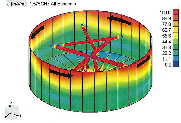
Circumferential Current Reduction. Through many EM simulations of the antenna structure, it was found that the LHCP could be suppressed substantially by making the aperture of the cup serrated. The EM wave simulation package allows the user to look at the currents in the structure. The results are shown in FIGURE 2.

The strong circumferential currents (horizontal linear currents) produce radiation with linear horizontal polarization. It is important to reduce the size of these currents to minimize the linearly polarized radiation. The horizontal currents flowing in the top of the waveguide wall are effective in setting up horizontal polarization (HP) radiation in the direction of the horizon. For high-quality CP radiation, the horizontal radiation must be matched by vertical radiation (with a 90-degree phase shift), but the waveguide wall does not permit the required vertical current to flow to produce the vertical polarization (VP) radiation component. Clearly, a serrated waveguide aperture reduces the circumferential current flow. It was also found, through many simulations, that the unwanted polarization components can be reduced by tapering the cup towards the bottom end (see Figure 2).
The sawtooth aperture antenna was chosen for further development. The fed dipoles are constructed using PCB technology and are given shapes that vary from the wire dipole case. The radiating resonator is also constructed using PCB material and is given a different shape from the pure straight-wire case. The software antenna was constructed and tested and found to have good performance with regard to low cross polarization in all directions, low backward radiation and high radiation efficiency.
Further Waveguide Development. It was decided that another way of achieving vertical currents and horizontal currents that would be balanced in magnitude and have a 90-degree phase difference might be obtained by constructing the waveguide walls from a combination of thin conductors connected in a grid. The grid consists of a combination of vertical and horizontal conductors. Simulations with EM software showed the antenna is exceptionally efficient when it uses wires. The wire grid waveguide model of the GNSS antenna was simulated with many, many topological variations. Each variation was optimized for low back (nadir) radiation and high-purity RHCP in all directions. The results were unexpected. The best results were obtained when only one circumferential wire conductor is used and, furthermore, the vertical wire conductors are not connected to the circumferential conductor nor to the base of the antenna. This structure was simulated and optimized many times to derive the best possible topological configuration and component dimensions for a GNSS antenna. A PCB model of the GNSS antenna was then numerically constructed, simulated and optimized as a more practical construction technology for the antenna (see FIGURE 3).
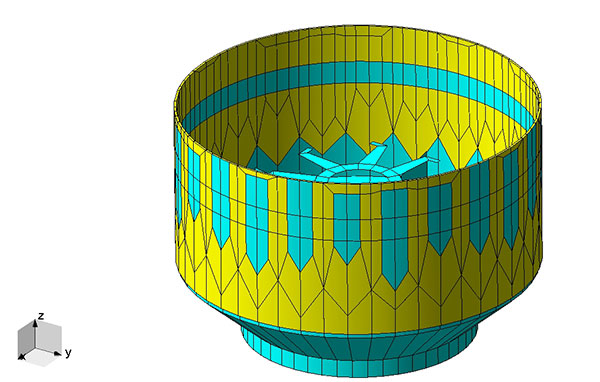
Note that the vertical strip conductors do not contact the conducting antenna base. Also note the serrated antenna base, as seen on the inside of the antenna. This design feature reduces excessive circumferential current flow in the base of the antenna. The antenna was tested in the University of Calgary anechoic chamber and in the high-quality Simon Fraser University anechoic chamber (a Satimo SG64), and it was found to have well-suppressed LHCP radiation, very low back radiation and very stable phase centers.
The unique topology of this last antenna provides suppression of the expected downward LHCP radiation that most CP antennas exhibit. Radiation tends to “spill over” from the aperture and travel downwards. Downward radiation also emerges from the gap between the antenna base and the vertical conductors. These two sources of downward radiation are largely out of phase and tend to cancel each other out. This reduced downward LHCP radiation largely removes the need for a choke ring to block the reflections from the ground. This in turn means that the antenna can be compact and light.
ANTENNA DEVELOPMENT
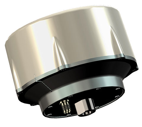
We undertook the project of converting the research prototype antenna described above into a commercially viable product. The research prototype antenna was modified to achieve optimized gain at lower GNSS frequencies, high mechanical robustness, adaptation for efficient manufacturability and for use of different materials. This antenna is known as the VeraPhase VP6000 antenna and is shown in FIGURE 4.
The topology of the antenna follows that of the research prototype with dimensional adjustments so as to function correctly with the new materials and circuitry being used. It is light and compact with a diameter of 157 millimeters, a height of 137 millimeters and a weight of less than 670 grams.
VeraPhase Measurements. Anechoic chamber tests were conducted at the Satimo facility in Kennesaw, Georgia, to determine the gain pattern, axial ratio, phase-center offset and variation in multipath-free conditions. Data were collected from 1160 MHz to 1610 MHz to cover all the GNSS frequencies.
Antenna Gain, Efficiency and Roll-off. The chamber measurements show that the VP6000 exhibits a gain at zenith from 4.9 dBic at 1164 MHz to 7.05 dBic at 1610 MHz (see FIGURE 5). This high gain in combination with a wideband pre-filtered low-noise amplifier (LNA) with a noise figure of 2 dB provides for high carrier-to-noise density (C/N0) ratios for all GNSS frequencies. Furthermore, the VP6000 exhibits gain at the horizon from –4.4 dBic at 1164 MHz to –6.8 dBic at 1610 MHz (see Figure 5).
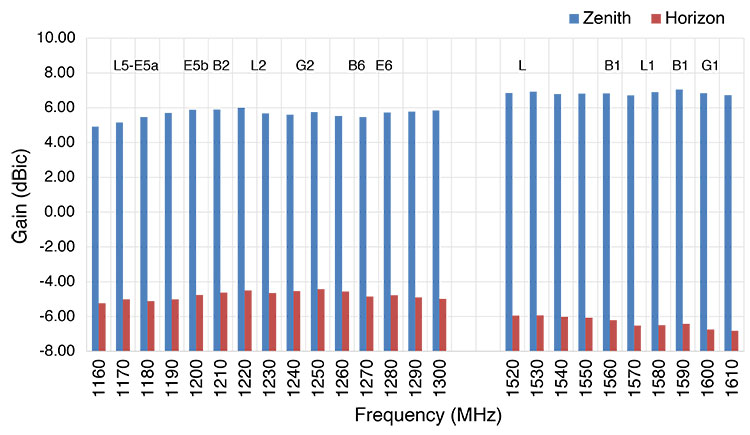
Thus, the gain roll-off from zenith to horizon is between 10.1 dB and 13.6 dB, providing for good tracking at low elevation angles. The radiation efficiency of the VP6000 is 70 percent to 80 percent, corresponding to an inherent (“hidden”) loss of just 1 dB to 1.5 dB, which includes all feedline, matching circuit and 90-degree hybrid coupler losses. In contrast, spiral antennas usually exhibit an inherent efficiency loss of close to 4 dB in the lower GNSS frequencies. Thus, with a high performance LNA, high values of gain translate into higher C/N0 ratios.
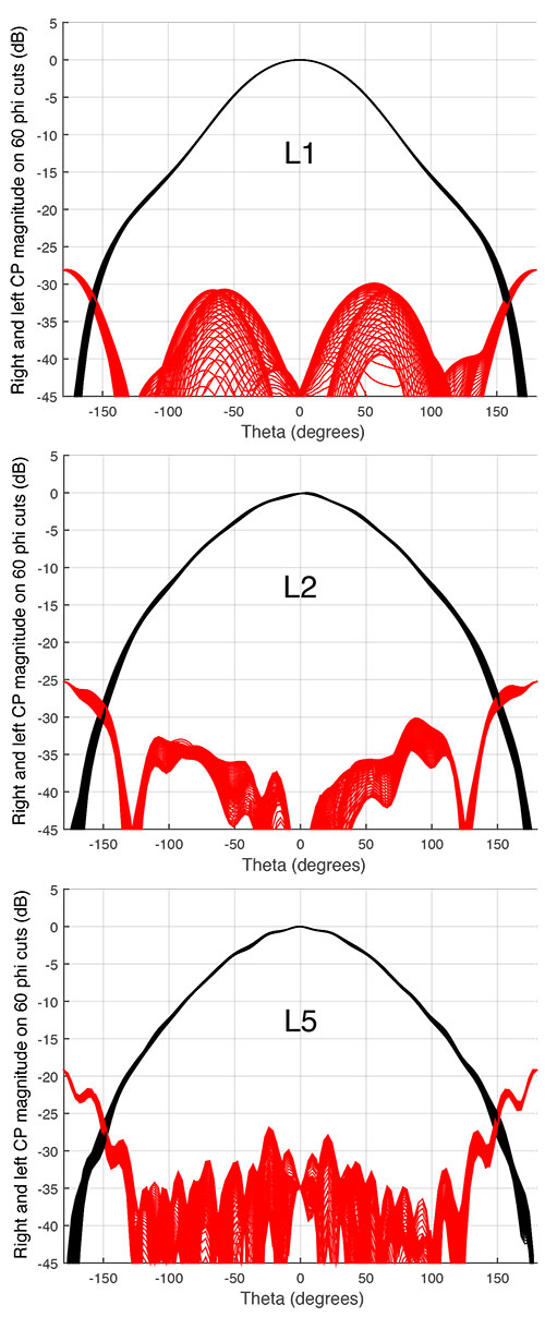
Radiation Patterns. The radiation pattern of an idealized antenna would have pure CP and constant high gain from zenith down to the horizon and then roll off rapidly for elevation angles below the horizon. In a realizable antenna, the gain should be close to constant over all azimuths for each elevation angle, with strong cross-polarization rejection over that frequency range. The phase-center offset should be stable with minimal phase-center variation. In the upper hemisphere, the greater the difference between the RHCP and LHCP antenna gain, the greater the resistance of the antenna to cross-polarized signals, usually associated with odd order reflections, and hence improved multipath signal rejection. The measured radiation patterns at GPS frequencies are shown in FIGURE 6.
The radiation patterns are normalized to enable direct comparison of the patterns and show the RHCP and LHCP gains on 60 azimuth cuts three degrees apart. The radiation patterns show excellent suppression of the LHCP signals in the upper hemisphere. Similar results were found for all the other GNSS frequencies. The difference between the RHCP gain and the LHCP gain at zenith ensures an excellent discrimination ranging from 31 dB to 53 dB. Also, for the other elevation angles the LHCP signals usually stay 25 dB below the maximum RHCP gain and even 30 dB from 1200 MHz to 1580 MHz. The antenna shows a constant amplitude response to signals coming at a constant elevation angle regardless of the azimuth or bearing angle. This illustrates the excellent multipath mitigation characteristics of the VP6000 at every elevation angle and every GNSS frequency.
Down-Up Ratio. When a direct satellite signal is reflected from the ground, the reflected signal polarization tends to convert, at least partially, from RHCP to LHCP for most soil types. If the terrain underneath the antenna is homogeneous, then the ground surface acts as a mirror, thus providing a reflected signal coming from below the horizon at the negative of the angle of the direct signal above the horizon. Depending on the angle, in part, the field of the inverted and reflected wave adds to the direct wave, which is undesirable. This is the reason, when characterizing the multipath reflection capabilities of an antenna, it is common to use a down-up ratio between antenna gain for LHCP signals for a given angle below the horizon as that for the RHCP signals at the same angle above the horizon. The down-up ratios at L2 and L1 are –25 dB at zenith and they stay under –20 dB for the upper hemisphere, which is usually not the case for standard GNSS antennas. Similar results have been measured over the whole range of GNSS frequencies and confirm the excellent multipath rejection capabilities of the VP6000.
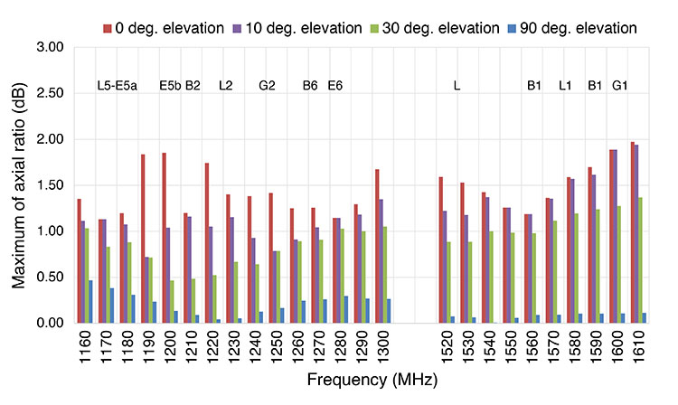
Axial Ratio. The axial ratio (AR) is a measure of an antenna’s ability to reject the cross-polarized portion of a composite signal with both RHCP and LHCP components. Physically, this is an elliptical wave, typically being the combination of the direct and reflected signals from the satellite. The lower the ratio of the major axis to the minor axis of the polarization ellipse, the better the multipath rejection capability of the antenna. To meet operational standards for a multi-band antenna, the axial ratio should meet these requirements at the following elevation angles:
- 45–90 degrees: not to exceed 3 dB
- 15–45 degrees: not to exceed 6 dB
- 5–15 degrees: not to exceed 8 dB.
The worst AR ratio values of the VP6000 at different elevation angles have been plotted in FIGURE 7. The graph shows an AR of less than 0.5 dB at zenith for all GNSS frequencies, and the ARs stay low at all elevation angles down to the horizon. A maximum value of 1.5 dB has been measured for elevation angles above 30 degrees, increasing to just 2 dB at the horizon (0 degree elevation angle) for the worst case azimuth. This performance contributes to the excellent multipath rejection capability of the VP6000.
Phase-Center Offset / Phase-Center Variation and Absolute Calibration. For use as a measurement instrument, the antenna must have a precise origin, equivalent to a tape measure zero mark. Thus, it is important that the phase of the waves received by the antenna “appear” to arrive at a single point that is independent of the elevation angle and azimuth of the incoming wave. This point is known as the phase center of the antenna, which should remain fixed for all operational frequencies and for all azimuth and elevation angles of incoming waves, otherwise dimensional measurement is compromised.
In an ideal GNSS antenna, the phase center would correspond exactly with the physical center of the antenna housing. In practice, it varies with the changing azimuth and elevation angle of the satellite signal. The difference between the electrical phase center and an accessible location amenable to measurement on the antenna is described by the phase-center offset (PCO) and phase-center variation (PCV) parameters and their values are determined through antenna calibration.
These corrections are only effective if the predicted phase-center movement is repeatable for all antennas of the same model. The PCO is calculated for each measured elevation angle by considering the signal phase output for all phi (azimuth) values at a specific theta (elevation) angle, and mathematical removal of the normal phase-windup effect in this type of antenna.
A Fourier analysis is then conducted on this resulting data. The fundamental output gives the variation of the horizontal position of the antenna as it is rotated about the z axis. The apparent position normally varies somewhat as the antenna is viewed from various theta angles. The PCV measurement of the VP6000 showed the variation of the phase center in the horizontal plane for elevation angles of 18 to 90 degrees in 3-degree steps at different frequencies. The variations for the different GNSS signals are typically less than 1 millimeter from the x and y axes. Repeatability of the PCO and PCV over several VP6000 antennas has been measured and is also less than 0.5 millimeters.
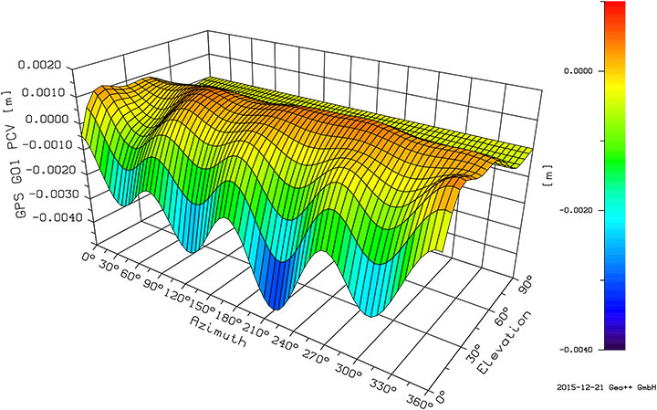
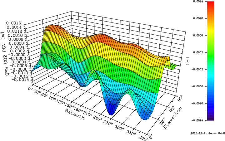
Five copies of the antenna were sent for absolute calibration by Geo++ in Germany where the VP6000 has been calibrated at GPS L1/L2 and GLONASS G1/G2 signal frequencies. The PCV for the upper hemisphere of the VP6000 at L1 and L2 are plotted in FIGURES 8 and 9. These results confirm a ±1-millimeter PCV at L1 and a ±1-millimeter PCV at L2. Also the standard deviation of the PCV over the five measured antennas stayed under 0.2 millimeters, which represents excellent repeatability. The same results have been observed at G1 and G2.
LNA and Optional Circuitry. The best achievable C/N0 for signals with marginal power flux density is limited by the efficiency of each antenna element, the gain and the overall receiver noise figure. This can be quantified by a ratio parameter, usually referred to as G/T, where G is the antenna gain (in a specific direction) and T is the effective noise temperature of the receiver — usually dominated by the noise figure of the input LNA.
In the VP6000 LNA, the received signal is split into the lower GNSS frequencies (from 1160 MHz to 1300 MHz) and the higher GNSS frequencies (from 1525 MHz to 1610 MHz) in a diplexer connected directly to the antenna terminals and then pre-filtered in each band. This is where the high gain and high efficiency of the basic VP6000 antenna element provides a starting advantage, since the losses introduced by the diplexer and filters are offset by the higher antenna gain, thereby preserving the all-important G/T ratio.
That being said, GNSS receivers must accommodate a crowded RF spectrum, and there are a number of high-level, potentially interfering signals that can saturate and desensitize GNSS receivers. These include, for example, the Industrial, Scientific and Medical (ISM) band signals and mobile phone signals, particularly Long-Term Evolution (LTE) signals in the newer 700-MHz band, which are a hazard because of the potential for harmonic generation in the GNSS LNA. Other potentially interfering signals include Globalstar (1610 MHz to 1618.25 MHz) and Iridium (1616 MHz to 1626 MHz) because they are high-power uplink signals and particularly close in frequency to GLONASS signals. The VP6000 LNA is a compromise between ultimate sensitivity and ultimate interference rejection.
A first defensive measure in the VP6000 LNA is the addition of multi-element bandpass filters at the antenna element terminals (ahead of the LNA). These have a typical insertion loss of 1 dB because of their tight passband and steep rejection characteristics. Sadly, there is no free lunch, and the LNA noise figure is increased approximately by the additional filter-insertion loss.
The second defensive measure in the VP6000 LNA is the use of an LNA with high linearity, which is achieved without any significant increase in LNA power consumption, by use of LNA chips that employ negative feedback to provide well-controlled impedance and gain over a very wide bandwidth with considerably improved linearity.
Bear in mind that while an installation might initially be determined to have an uncluttered environment, subsequent introduction of new services may change this, so interference defenses are prudent even in a clean environment. A potentially undesirable side effect of tight pre-filters is the possible dispersion that can result from variable group delay across the filter passband. Thus it is important to include these criteria in selection of suitable pre-filters. The filters in the VP6000 LNA give rise to a maximum variation of 2 nanoseconds in group delay over the lower GNSS frequencies (from 1160 MHz to 1300 MHz) and 2.5 nanoseconds over the higher GNSS frequencies (from 1525 MHz to 1610 MHz). Also, the difference in group delay between the lower GNSS frequencies and the higher GNSS frequencies stays less than 5 nanoseconds.
The VP6000 series antennas are available with either a 35-dB gain LNA or with a 50-dB gain LNA for installations with long coaxial cable runs. The VP6000 is internally regulated to allow a supply voltage from 2.7 volts to 26 volts.
An interesting feature of the VP6000 is that the physical housing includes a secondary shielded PCB that is available for integration of custom circuits or systems within the antenna. This allows the addition of L1/L2 receivers for real-time kinematic operation, for example. A pre-filtered, 15-dB pre-amp version of the LNA is also available to provide RF input for OEM systems embedded within the antenna housing.
The VP6000 is available with a variety of connectors and with a conical radome to shed ice and snow and to deter birds for reference antenna installations. A precise and robust monument mount is also available.
CONCLUSION
In this article, we have described a research program that developed a series of CP antennas, which have increasingly improved performances directed towards GNSS applications. The resulting research CP prototype antenna has a very low cross-polarization, very low back radiation, very high phase-center stability and a compact structure. We have converted the research prototype into a commercially viable GNSS antenna with the superior electrical properties of the research prototype while building into the antenna the required physical ruggedness and manufacturability required of the commercial antenna.
With emerging satellite systems on the horizon, a new high-performance antenna is needed to encompass all GNSS signals. Our new antenna has sufficient bandwidth to receive all existing and currently planned GNSS signals, while providing high performance standards. Testing of the antenna has shown that the new innovative design (crossed driven dipoles associated with a coupled radiating element combined with a high performance LNA) has good performance, especially with respect to axial ratios, cross-polarization discrimination and phase-center variation.
These improvements make the antenna an ideal candidate for low-elevation-angle tracking. The reception of the proposed new signals along with additional low-elevation-angle satellites will bring new levels of positional accuracy to reference networks, and benefits to the end users of the data. With its compact size and light weight, the antenna has been designed and built for durability and will stand the test of time, even in the harshest of environments.
ACKNOWLEDGMENT
This article is based, in part, on the paper “The Evolutionary Development and Performance of the VeraPhase GNSS Antenna” presented at the 2016 International Technical Meeting of The Institute of Navigation held in Monterey, California, Jan. 25–28, 2016.
JULIEN HAUTCOEUR graduated in electronics systems engineering and industrial informatics from the Ecole Polytechnique de l’Université de Nantes, Nantes, France, and received a master’s degree in radio communications systems and electronics in 2007 and a Ph.D. degree in signal processing and telecommunications from the Institute of Electronics and Telecommunications of Université de Rennes 1, Rennes, France, in 2011. From 2011 to 2013, he obtained postdoctoral training with the Université du Québec en Outaouais, Gatineau, Canada. In 2014, he joined Tallysman Wireless Inc. in Ottawa, Canada, as an antenna and RF engineer.
RONALD H. JOHNSTON received a B.Sc. from the University of Alberta, Edmonton, Canada, in 1961 and the Ph.D. and D.I.C. from the University of London and Imperial College (both in London, U.K.) respectively, in 1967. In 1970, he joined the University of Calgary, Canada, and has held assistant to full professor positions and was the head of the Department of Electrical and Computer Engineering from 1997 to 2002. He became professor emeritus in the Schulich School of Engineering in 2006.
GYLES PANTHER is a technology industry veteran with more than 40 years of engineering, corporate management and entrepreneurial experience. He spent the first 20 years of his career in the semiconductor industry, first with Plessey in the U.K., then in Canada with Microsystems International. Panther co-founded and acted as engineering vice president and chief technology officer (CTO) for Siltronics, followed by SilCom and SiGem. In 2002, he founded startup Wi-Sys Communications, acting as president and CTO. He is now president and CTO of Tallysman Wireless, his fourth successful start-up, which was founded in 2009. Panther holds an honours degree in applied physics from City University, London, U.K.
FURTHER READING
- Authors’ Conference Paper
“The Evolutionary Development and Performance of the VeraPhase GNSS Antenna” by J. Hautcoeur, R.H. Johnston and G. Panther in Proceedings of ITM 2016, the 2016 International Technical Meeting of The Institute of Navigation, Monterey, California, Jan. 25–28, 2016, pp. 771–783.
- Early Circularly Polarized Antenna Designs
“Broadband Cup-Dipole and Cup-Turnstile Antennas” by J.J. Epis, United States Patent No. 3,740,754, June 19, 1973.
“Antennas for Circular Polarizations” by W. Sichak and S. Milazzo in Proceedings of the Institute of Radio Engineers, Vol. 36, No. 8, Aug. 1948, pp. 997–1001, doi: 10.1109/JRPROC.1948.231947.
- Antenna Modeling
Electromagnetic Modeling of Composite Metallic and Dielectric Structures by B.M. Kolundzija and A.R. Djordjevi, published by Artech House, Norwood, Massachusetts, 2002.
WIPL-D: Electromagnetic Modeling of Composite Metallic and Dielectric Structures – Software and User’s Manual by B.M. Kolundzija, J.S. Ognjanovic and T.K. Sarkar, published by Artech House, Norwood, Massachusetts, 2000.
- Measurement of Phase Center and Other Antenna Characteristics
“Determining the Three-Dimensional Phase Center of an Antenna” by Y. Chen and R.G.Vaughan in Proceedings of the XXXIth General Assembly and Scientific Symposium of the International Union of Radio Science (URSI), Beijing, Aug. 16–23, 2014, doi: 10.1109/URSIGASS.2014.6929023.
“Calibrating Antenna Phase Centers: A Tale of Two Methods” by B. Akrour, R. Santerre and A. Geiger in GPS World, Vol. 16, No. 2, Feb. 2005, pp. 49–53.
“Characterizing the Behavior of Geodetic GPS Antennas” by B.R. Schupler and T.A. Clark in GPS World, Vol. 12, No. 2, Feb. 2001, pp. 48–55.
- The Basics of GNSS Antennas
“GNSS Antennas: An Introduction to Bandwidth, Gain Pattern, Polarization, and All That” by G.J.K. Moernaut and D. Orban in GPS World, Vol. 20, No. 2, Feb. 2009, pp. 42–48.
“A Primer on GPS Antennas” by R.B. Langley in GPS World, Vol. 9, No. 7, July 1998, pp. 73–77.


