New players are offering GNSS correction services — pushing prices down and offering new business models. What opportunities does this open up?
Jules McNeff
“This trend is encouraging, as new entrants bring energy and new ideas, keeping the PNT technology sector fresh. GNSS corrections enhance the value of dynamic mapping coupled with grid-coordinate systems such as the U.S. National Grid in producing user-friendly geolocation values for delivery of people and things and especially enabling efficient, precise, land mobility activities such as spatial awareness for autonomous vehicle movement and command and control of emergency response operations.” — Jules McNeff Overlook Systems Technologies
Greg Turetzky
“In a 5G world where most devices regardless of size are connected, it make sense that those devices that are mobile are going to need to be located. Correction services are key to providing enhanced accuracy, and new business models are needed to address these new markets that are fundamentally different than traditional high-accuracy markets.” — Greg Turetzky Consultant
Jean-Marie Sleewaegen
“Traditional correction services rely on bidirectional communication between a user and a local correction provider. They offer centimeter accuracy over small regions. Instead, new services broadcast corrections applicable to larger areas and with flexible accuracy levels, from centimeters to decimeters. They bring benefits not only in pricing, but also in terms of accessibility, scalability and ease of use. They make accuracy transparent to the user, opening up the opportunity of high accuracy to mass-market and industrial applications.” — Jean-Marie Sleewaegen Septentrio
Thirty years ago, more than a decade before most people had even heard of GPS, receiver manufacturers and surveyors were already improving on it by providing and using correction services to compensate for errors in the system—including clock drift, orbit errors, signal errors, atmospheric errors and multipath.
Today, dozens of public and commercial correction services enable users to achieve accuracies of decimeters, centimeters or even millimeters. Also, many GNSS processing services correct measurements taken in the field using data from reference points. Increasing positioning accuracy has become the cornerstone of modern GNSS practice.
The current boom for correction services is driven mostly by the demand for high accuracy from the automotive industry (including the development of self-driving cars), as well as smart consumer devices and various forms of automation. Automotive companies and telecoms are deploying infrastructure around the globe to provide centimeter-level positioning. GNSS satellites also can transmit corrections directly, as the Japanese CLAS service from the QZSS constellation does, and Galileo’s High-Accuracy Service (HAS) soon will. To compensate for receiver-side issues — multipath, jamming and spoofing — some GNSS receivers also incorporate advanced positioning algorithms.
Clock and orbit errors are specific to each satellite; they do not depend on the position of the receiver. But atmospheric errors are introduced when the signal travels from the satellites to the user. Reference stations (base stations) of GNSS receivers installed at fixed and precisely surveyed positions provide corrections that compensate for both sets of errors to the rovers carried by field crews. When connected, reference receivers spread over a geographic area form reference networks, such as that of continuously operating reference stations (CORS). Achieving maximum accuracy requires initializing the receiver, which can take a few seconds to several minutes, depending on the type of corrections.
Established and new methods
Two established methods have been used for decades.
Real-time kinematic (RTK). In RTK, a receiver obtains correction data from a single base station or a local reference network in the same area.
Precise point positioning (PPP). While accessible from anywhere in the world, receiver initialization for PPP can take up to 30 minutes. Also, a few PPP correction services only provide corrections for satellite clock and orbit errors and not for atmospheric errors, limiting users to a lower accuracy level than with RTK.
Hybrid PPP-RTK. In recent years, new methods have emerged. Hybrid PPP-RTK combines near-RTK accuracy and quick initialization times with the global access of PPP. It relies on a network of reference stations within about 150 kilometers of each other. The stations collect GNSS data and calculate both satellite and atmospheric correction models. The network then broadcasts these corrections via internet, satellites or cellphone towers to subscribers, who can use them to achieve sub-decimeter accuracy.
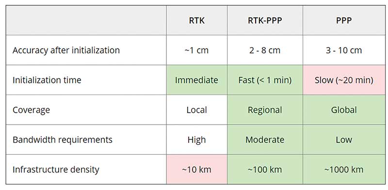
Each of these methods has advantages and disadvantages (see table 1). RTK, which relies on communication between the user and the local correction service, provides centimeter accuracy over small areas. PPP-RTK and PPP broadcast corrections and require a lighter infrastructure, making them scalable for mass-market and industrial applications. The new services are cheaper and more user-friendly than traditional correction services.
TABLE 1: Differences of various correction methods. (Chart: Septentrio)
CORS/VRS
Traditional reference networks — often called CORS or virtual reference station (VRS) networks — have long been a source of differential GPS (DGPS) and RTK corrections, mainly for surveying and mapping applications, which require high accuracies.
“Most CORS in the United States are strictly for providing high-accuracy correction data to GNSS users who need to know their position to less than an inch,” said Alex Ngu, applications engineer at Trimble. “However, some — like Utah’s TurnGPS network and the North Carolina Geodetic Survey (NCGS) — have considered dabbling in using them to double up for weather monitoring.” In some regions, such as Japan and Washington state, CORS are also used to study plate tectonics and provide early warning of earthquakes.
CORS receivers often operate in remote locations and may be powered by solar panels. Therefore, they require low power consumption and the ability to configure, run and update remotely. They also need to archive on-board measurements and withstand harsh environments.
Changes in the market
As the market for GNSS corrections changes, so does the role of CORS networks. They are increasingly used for industrial automation that needs centimeter accuracy, including construction and agriculture. “Now, due to the growth in autonomous systems, such as autonomous cars, people are looking at corrections in a completely different way and with more focus on mass markets,” said Gustavo Lopez, market access manager at Septentrio. Septentrio lets customers choose which correction service to use.
“CORS/VRS networks will keep focus on performance and on adding constellations and signals, but nothing major is expected to happen in these traditional systems,” Lopez said. They will continue to exist because they focus on centimeter-level accuracy for survey, construction, mining, machine control and precision agriculture. “What will really change the market are these new services with 10-cm to 20-cm accuracies, which also offer a new way of delivering the data, namely broadcasting rather than using two-way communication methods.” This helps with adoption by emerging applications, Lopez said.
He predicts that applications needing 10- to 50-centimeter acurcy will migrate to cheaper services, including new consumer applications, advanced driver-assistance systems (ADAS), professional applications such as robotics, UAVs, logistics and internet of things (IoT) applications.
Mobile technologies adopting dual-frequency chipsets also will need correction services. “We will see more and more telecoms interested in providing GNSS corrections as a service, as is already the case in Asia and Europe,” Lopez said. “A few CORS/VRS networks will try to capture part of this emerging applications market by reusing their technology or partnering with other companies to provide a more transparent solution.”
One might think that the rapid expansion of the market for corrections would make it possible for traditional CORS networks to make 1-cm accuracy available at a much lower price. The roadblock is high infrastructure costs, Lopez explained. CORS/VRS networks are expensive to maintain because they require a high density of stations. New services that use broadcasting technology and PPP-RTK positioning modes rely on less dense networks.
New uses for old CORS
A key benefit of a VRS is that performing RTK positioning across the area it covers does not require guarding a separate GPS base station. Using VRS, the CORS network acts essentially as a continuous reference station within the entire network, enabling RTK positioning using a single rover in the field.
Randy Osborne, VRS network manager at Louisiana State University’s Center for GeoInformatics, reports a growth in new applications beyond surveyors. VRS expanded to precision agriculture, and then into applications such as lidar and UAVs. “We are also seeing strange applications that we never thought of. For example, plumbing companies use it to navigate underground from a truck that has a position on the network, and then they vector from the truck underground into pipelines,” Osborne said. Subscribers also include companies performing survey work for fracking and petrochemical projects.
OSR vs. SSR
Most GNSS correction services are based either on the observation state representation (OSR) or on a state space representation (SSR) of the errors. OSR and SSR use different techniques, delivery mechanisms and core technologies.
OSR. Legacy GNSS correction service providers supply OSR correction services; examples are RTK and networked RTK (RTN). They rely on transferring corrected GNSS observations from the nearest reference station to the rover using a standardized format. They focus on a geographic region and target surveying, machine control and precision agriculture, providing centimeter-level accuracy up to about 30 kilometers of the nearest reference station. Because these services require bi-directional communications and large bandwidth, it is hard to ramp them up for mass-market applications.
SSR. By contrast, new players in the market for correction services, as well as some of the larger legacy ones, provide SSR correction services. SSR uses a network of reference stations to model major errors over large areas. They then transfer this model to the rovers, which create local error models and apply them to their GNSS observations. Depending on the service, accuracy ranges from less than 5 cm to 20 cm, convergence times from 10 seconds to 30 minutes, and coverage from continental to global. Because SSR corrections are broadcast, they can be more easily distributed through internet connections and L-band satellite channels. Because all the rovers rely on the same stream of GNSS correction data, SSR services work well for mass-market applications. The growth in SSR technology is driven mainly by the needs of the automotive industry but is sufficiently generic for adoption in other markets.
The challenge of vertical accuracy
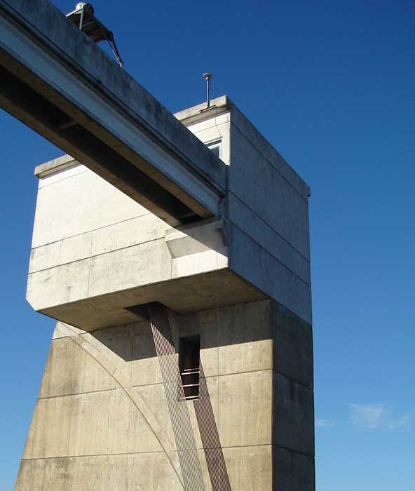
A CORS receiver stands atop the Old River Auxiliary Control Structure, a floodgate system in a branch of the Mississippi in central Louisiana. (Photo: Trimble)
While OSR and SSR have comparable accuracies on a horizontal plane, they differ greatly in their vertical accuracy and initialization times, Osborne said. “When we look at CORS for active control and positioning in the National Spatial Reference System, we are mainly trying to get a handle on the vertical part, as it is the hard problem to solve,” he said.
High-precision vertical accuracy is a challenge for any GNSS-based method. Conventional surveying is still the gold standard. With differential leveling, like with digital levels, results in millimeters are possible. Post-processed GNSS, using data from a good geometry of CORS or base data, can yield results under 2 cm vertical, as can real-time OSR methods like RTK and RTN. SSR solutions, like PPP and hybrids, are presently achieving 5 cm at best. An Achilles heel for SSR vertical solutions is the lack of data for localized sources of error, like tropospheric conditions. Semi-dense networks of CORS can feed ionospheric data to speed PPP convergence, but not the level of tropospheric data needed to match the vertical results that OSR and conventional methods can.
Trimble
Trimble GNSS base-station receivers have been used for 40 years on every continent, according to the company. Today, products in use as CORS stations typically are Alloys, NetR9s and NetR5s. The company operates more than 300 networks worldwide, incorporating more than 5,000 CORS receivers.
Trimble offers a full spectrum of solutions, services and subscriptions related to CORS networks. They range from supplying CORS software, hardware and services, to providing network management services to run a secondary backup system for a network, or even operating a network on behalf of its owner. For those who just want a high-accuracy correction to support their surveying, GIS or machine guidance and control work, “Trimble operates one of the largest CORS networks in the world to which users can subscribe — Trimble VRS Now, Trimble RTX and OmniSTAR services,” Ngu said.
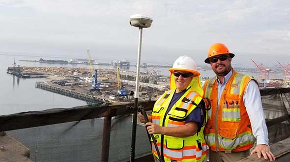
Feature photo:
In Long Beach, California, correction services support the 250-foot-high Gerald Desmond Bridge project. Trevor Rice (left), president of D. Woolley & Associates, joins Kimberley Holtz, director of survey, Port of Long Beach. (Photo: Trimble)
The creed “Neither snow nor rain nor heat” may apply to postal workers, but it also could apply to land surveyors.
Today’s surveyors rely on GNSS as a critical tool to enable completion of their tasks, whether defining a property boundary or mapping mining drill sites.
In the articles that follow, surveyors share their success stories using the latest GNSS receivers, software and correction services, all of which are constantly improving to make their tasks easier — despite the terrain or weather conditions.
How one man triumphs
Adam Plumley is a one-man surveying shop in North Carolina. He also wears another hat as a sales, support and product development consultant to Javad GNSS.
“As a land surveyor, I use the equipment every day,” Plumley said. “Javad’s equipment has made it possible for me to operate solo.”
Photo: Stephen Drake
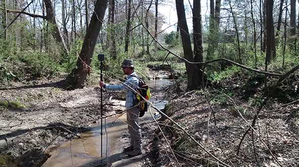
In the project pictured above, Plumley surveyed a 50-acre farm parcel to separate out the six-acre improved northeast corner. “I located the creek, building and improvements on the property east of the road and ran the lines to the creek on the west side of the road.”
The difficult locations on this 2016 survey were at the creeks. It took Plumley up to a half hour to locate the corners and creek points under the tree canopy.
“It would have taken much longer than it did if I had traversed the boundary conventionally,” he said, “not to mention I would have been much more tired at the end of the day.”
Instead, Plumley used a Javad GNSS Triumph LS and Triumph 2 base/rover system with corrections broadcast over the internet.
“I set up the Triumph 2 base about one mile away in an open yard with great sky view. It took me one day to do the initial recon and locations, and another couple of hours to set the new corners the next day,” he said.
Plumley has since upgraded his base receiver to another Triumph LS and added a J-Link 35-watt external radio to his toolbox.
“One thing this and other challenging surveys have taught me is to be patient. To obtain accurate results that you can be confident in takes time.”
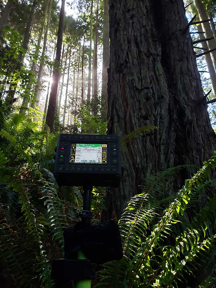
About our cover
Our cover photo this month was taken in June 2019 by surveyor Stephen Drake, near his home on the north coast of California. “These redwood forests and very rugged, remote coastal mountains can really test you,” he said. He was using his Javad Triumph-LS rover with the J-Field built-in surveying software, communicating to a Javad GNSS Triumph-2 base station attached to his house. A Verizon Jetpac mobile hotspot (in the black pack hanging below the Triumph-LS in the photo) picks up signals from his home router; the port-forwarded corrections are configured with Javad software.
Stephen calls this his standard configuration, but finds it very flexible. When he is more than 20 miles from home base, he relies on a Triumph-2 and a radio modem placed near the site. He can also use the California Real Time Network (CRTN) with the Jetpac.
He also relies on Javad’s Hybrid RTK, automated post-processing with Javad’s DPOS, automatically generated raw data and quality reports, and the many built-in indicators in J-Field that provide real-time feedback and “give me assurance on almost every measurement before I walk away from it,” he said.
The efficiency that his equipment provides has made Stephen valuable even to firms that already have in-house surveyors, he said. “I honestly do not think I would be here without Javad. It has been a true potent business partner.”
Empowered by a high-precision inertial measurement unit (IMU) on the Ultimate version, the Oscar from Tersus GNSS is a new generation of tilt survey receiver. Its calibration-free tilt compensation is immune to magnetic disturbances — holding the survey pole upright is no longer necessary. Powered by Tersus ExtremeRTK GNSS technology, Oscar can provide high accuracy and stable signal detection.
The built-in high-performance antenna can speed the time to first fix (TTFF) and improves anti-jamming performance. With a Nano-SIM card, Oscar can access the internet and transmit and receive correction data through 4G/Wi-Fi. The built-in UHF radio module supports long-distance communication. A detachable smart battery can display power levels. Two batteries support up to 16 hours of fieldwork in 4G/3G/2G-network and rover-radio mode. Oscar can be configured through a 1.54-inch interactive screen on the Ultimate and Advanced versions. The IP67-rated rugged housing protects it from harsh environments.
The Tersus Caster Service (TCS) helps surveyors set up a GNSS base station quickly to broadcast a correction stream via mobile networks. Natively supported by FieldGenius and Nuwa App, Oscar can be configured to different work modes to suit various daily jobs.
Satellite Tracking. Oscar supports multi-constellation and multi-frequency satellite tracking, including GPS, GLONASS, BeiDou, Galileo, SBAS and QZSS.
Accuracy. With enhanced positioning accuracy and constellation tracking, even in harsh environments, Oscar controls deviation within 3cm in surveying and mapping applications.
Quick Fix. Oscar can fix integer ambiguity rapidly after tracking satellites and receiving correction data: 3–5 seconds in the open sky, and 10–30 seconds under canopy or near buildings.
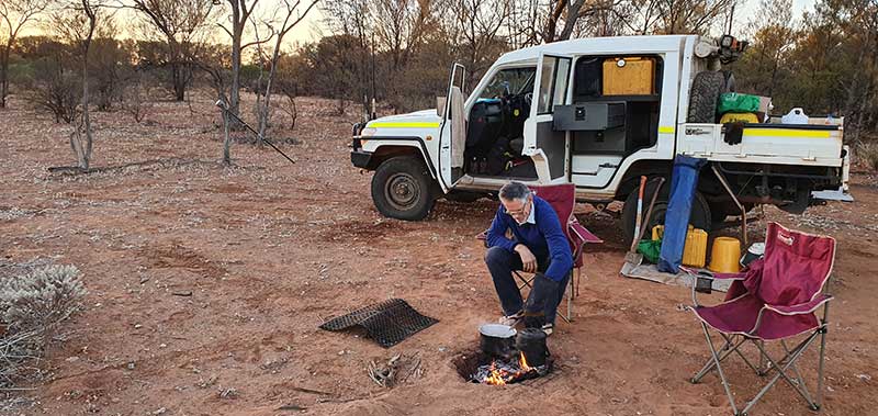
When someone imagines the Australian outback, they’re picturing Australia’s largest state, Western Australia (WA), which occupies an entire third of the continent.
Nearly all WA residents live in Perth, with the rest of WA reminiscent of the United States’ historic Wild West — sparsely populated towns with little infrastructure. That wild beauty and remoteness can also make surveying a less-than-beautiful experience.
“The outback of WA is a real test on my adaptability and logistics skills,” said Phil Richards, a professional surveyor and associate director with Perth-based RM Surveys. “It can take 1.5 days to get to your first site and once there, you’re totally isolated with no resources — and climate conditions that can range from 0 to 50 degrees Celsius. The sparse, rugged road systems make navigating anywhere a long journey. And if the weather turns bad on your job and you didn’t plan well, you could be completely stranded.”
Technological challenges that add to the complexity: limited mobile phone service, time-consuming RTK base station setups, inconsistent RTK cellular or radio communication, and geodetic control points that are difficult to access.
Advances in precise point positioning (PPP) technology, however, have been helping to resolve these obstacles and enable surveyors to optimize their real-time productivity without sacrificing accuracy. For Richards, who specializes in remote surveying work, this modern GNSS enhancement has helped bring a little tameness to the wilds of WA, enabling him to increase data collection efficiencies, reduce costs and boost the company’s bottom line.
Camp breakfast: The R10 receiver rests on a spur while Phil Richards dines out. (Photo: Trimble)
The case for a new approach
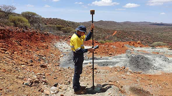
With his aptitude for remote surveying, much of Richards’ project work in WA has been in support of heavily active mining companies. For example, for the past 15 years, one iron ore producer has contracted him to travel more than 600 kilometers from Perth to measure exploratory drill hole collars. Drill collars, the remnants of drilling activity, are 3-millimeter-thick segments of PVC, about 150 mm in diameter, which protrude about 300 mm out of the ground, typically at a 60-degree angle. Measuring the center of that above-surface collar is a crucial stage in the exploration process to enable the client to develop a geological model of the mineral resource underground.
Managing 10 prospect sites across 300 km, the number of drill holes can vary from year to year, but there can be as many as 100 holes spread out over a few prospects at a time. Since 2007, Richards has been using Trimble R8 and, more recently, Trimble R10 GNSS receivers and RTK technology to acquire the drill-collar measurements.
On average, each prospect is 5 km by 2 km and has its own coordinate network. Depending on the number of collars and the distance to each, Richards would set up between two and nine RTK base stations on known control points to set project control. Using his Trimble GNSS receiver, he’d either drive or walk to each drill collar, set the foot of the range pole on the center of the collar at ground level, take a reading and record the measurement in Trimble Access field software on a Trimble TSC3 controller. Although the need for multiple base stations had added hours onto the projects, the RTK method consistently provided the needed accuracy.
X hits the spot
In 2015, the iron ore company restructured its mineral exploration program. Rather than drill numerous exploratory holes across a few prospects, the new focus was to drill fewer holes spread over the entire project area. That was going to be problematic for Richards’ traditional RTK routine.
“Previously, when it was predominantly surveying and less traveling, the RTK approach worked well for the project, even though setting up base stations is time consuming,” said Richards. “But when that switched to less surveying and more traveling, continuing with RTK was going to increase costs because each time I have to set up my base station, that’s an extra hour. If I have 10 drill-collar zones, that’s 10 hours. And if my base station is 10 minutes away, it adds more time and expense if I have a problem with it, or I can’t get a reliable signal, and I have to travel back to it to fix it or move it. The reduced number of collars and the increased distances between them required a more efficient method to make the project profitable.”
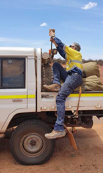
Taking the R10 off the vehicle mount. (Photo: Trimble)
Richards decided to test Trimble’s CenterPoint RTX correction service as an alternative. CenterPoint RTX is built on a network of GNSS tracking stations around the world that stream multi-frequency, multi-constellation data to the company’s network control centers. Advanced data processing algorithms analyze the three main error sources: satellite orbits, clock offsets and atmospheric effects, and develop models and correction data. This information is delivered to GNSS rovers via L-band satellite communications. The rover combines the correction data with its own satellite observations to produce accurate positions.
Richards ran five trials in conjunction with varied exploration surveys at test sites across 1,000 km of terrain. He took RTX measurements of survey control points with his R10 and compared them to the same positions acquired with RTK. Although the CenterPoint RTX can take up to 15 minutes to reach sub-2-centimeter horizontal accuracy in WA, Richards said the technology regularly delivered on performance. Most importantly, this technique enabled him to work without a base station and obtain real-time GNSS positions with centimeter accuracy even in isolated WA.
Integrating Trimble’s CenterPoint RTX into his workflows enabled Richard to use a single GNSS receiver system, much like working within the VRS networks available in the more populated areas of Australia.
Into the Outback
For the 2019 campaign, Richards and a colleague were contracted to acquire accurate 3D positions for 13 drill-collar holes stretched across two major prospects about 150 km apart. Their area of interest was 700 km northeast of Perth.
Within a 15-km-wide area, they had to acquire measurements for eight drill-collar holes. They calibrated the R10 receiver to the nearest control point to tie into the site’s coordinate system and moved through the area, methodically recording the positions of each collar hole. Despite the rough terrain, they finished both prospect sites in 1.5 days, compared to 2.5 days had they used RTK.
“Given the project format, with so much travel time and less surveying time, RTX is really the only way to do it,” Richards said. “It’s far quicker than setting up base stations — I saved 50% of the time using RTX on this campaign. I’m more efficient; I’m able to keep costs down; and I have the confidence in the system that I know I’ll deliver on accuracy. It’s hard to justify using any other method.”
Helping the guard: For the Kentucky Air National Guard, Sibole surveyed for paint lines on the taxiway for C-130 aircraft. (Photo: Matt Sibole)
Like Adam Plumley, Matt Sibole is also a solo surveyor and a Javad GNSS advocate. Based in Kentucky, Sibole tackles up to 140 jobs a year, which he would be unable to do using only a total station or a robotic station. Instead, he relies on the accuracy of GNSS.
He particularly relies on J-Field, the Javad GNSS data-collection software. When using the software’s “Boundary Profile” feature, he can get a fix, then re-initialize and get another fix that he can then compare in real time to the previous fix.
“J-Field keeps all fixes in memory to compare to each other, until you get a group of fixes that agree with each other to verify which fix is the correct fix,” Sibole explained. “We all know that a fix is not necessarily the ‘right’ fix. Javad’s J-Field program will give the user the confidence to know in real time that the shot is correct.”
“J-Field also has a relative accuracy calculator built in to verify that I meet minimum standards in the field before I leave the site,” Sibole said.
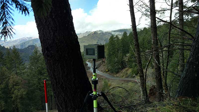
Up to the challenge: In a nine-month project, Drake’s team used a Triumph-LS for slope-staking along a four-mile stretch of California’s SR 36 near Dinsmore. The federal project will realign and improve the deadly switchback single-lane curves of the mountain pass. (Photo: Stephen Drake)
In the mountains of Northern California, a dangerously twisting stretch of road — the site of numerous fatal accidents — is being widened and realigned. Because it passes through the Six Rivers National Forest, the Highway 36 project is managed by the Federal Highway Administration (FHWA) in partnership with Caltrans.
Surveyor Stephen Drake and his wife and business partner Mary Drake are using the Javad GNSS Triumph-LS to tackle the tricky assignment.
“We started this job in June 2017 shortly after founding Lost Coast Land Surveying,” Stephen explained.
“We ran slope staking and culvert cross-section/staking through about March 2018. We returned off and on to do topo mapping in areas that had landslides and other control surveys to support Mercer-Fraser [the construction contractor] grade-checking crews. We provided the control they calibrated their GPS systems to, based on the control we received from FHWA and Caltrans.”
Because of various troubles, such as landslides, the project is still a season from finishing, though the Drakes’ contribution is mostly complete.
The Drakes had tackled similar jobs, including on the Chiniak Highway near Kodiak, Alaska. Still, the task was daunting. The surveyors had to set catch points every 50 feet for four miles on both sides of the highway, 200 feet upslope and 100 feet downslope. “I have learned that the way to the end is one stake at a time, start, and keep going,” Stephen said.
The couple had to juggle home life with three boys with long days at the job site. Sometimes Mary had to remain home. “Usually I tried to hit more moderate slopes on those days,” Stephen said. “We bounced around the project a bit, some days only covering a 250-foot stretch because it was slow going scaling the slopes.”
The FHWA contracting officer, a veteran Federal Highways engineer, marveled at the efficiency of the modern surveying methods used by the Drakes, telling Stephen that two six-man crews used to be needed to accomplish what the couple could today.
“I will attribute a huge part of our efficiency to the Triumph-LS advantage,” Drake said, as well as the couple’s 20-year track record in environments as diverse as the Arctic, the Everglades and Arizona.
“During the course of the project we received a lot of comments from ‘I don’t know how you are doing this’ to ‘You are superhuman’ at one point,” Stephen said. “But it is just being tough, tenacious and Javad.”
All told, the surveyors set more than 2,000 stakes. “We got the toughest part of the job going for them,” Stephen said.
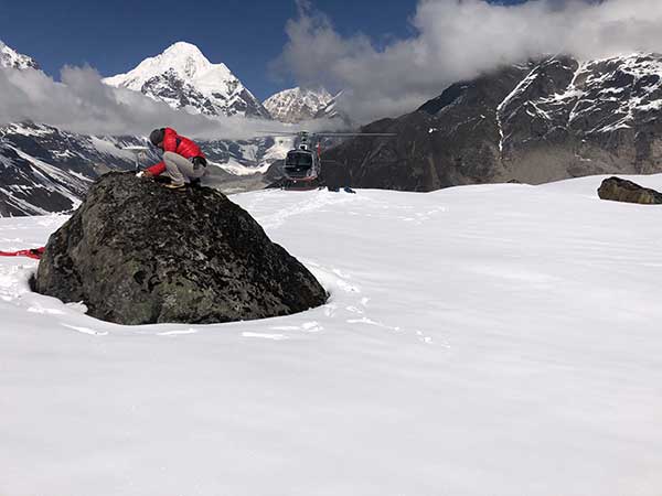
The Government of Nepal has completed fieldwork for measuring Everest’s height using GNSS equipment from Trimble, including the robust R10 receiver.
The Survey Department of the Government of Nepal has completed fieldwork for the National Initiative for the Measurement of the Height of Sagarmatha (Mount Everest). The Nepali survey team summited at 3 (local time) May 22, 2019 (by the Nepali calendar, that’s २०७६ जेठ ८, or June 8, 2076).
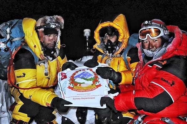
The summit team of Chief Survey Officer Khim Lal Gautam and Survey Officer Rabin Karki was supported by mountain guide Tshiring Jangbu and two of his fellow Sherpas.
The ascent was dark, windy and treacherous — the team had to make optimal use of the limited time that the hazardous conditions and their oxygen supplies afforded. The primary surveying task was to collect GNSS observations with the Trimble R10 GNSS receiver they carried.
On the summit: Chief Officer Khim Lal Gautam, Survey Officer Rabin Karki, Sherpa Tshiring Jangbu, and the Trimble R10. (Photo: Trimble)
Due to the limited time window on the summit, they had essentially one shot at the GNSS observations. The R10 was configured to begin collecting observations on power-up. During training and test observations before the ascent, the R10 had proven to be exceptionally reliable, with no malfunctions.
Compact size, light weight and durability were important factors for the receiver chosen for the summit observations. The IP67-rated R10 with internal battery weighs 1.12 kg (2.5 lb.) and operates in a temperature range of –40° C to +65° C (–40°F to +149° F). Its solid alloy housing withstands a 1-meter drop. The only concern for the team on the final ascent was to keep the battery and spares warm.
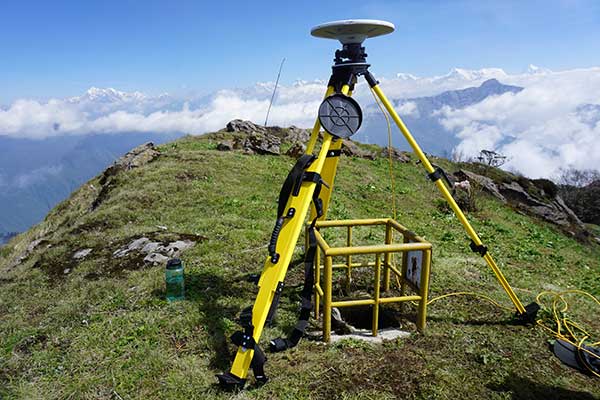
The R10 recorded 1 hour and 16 minutes of GNSS observations. The static data (observations from GPS, GLONASS, Galileo and BeiDou) was post-processed using Trimble Business Center software together with observations from eight GNSS reference stations established as an active control network for the survey. Several of the reference stations were Trimble NetR9 network receivers with Zephyr Geodetic antennas.
The team also used a compact ground penetrating radar (GPR) instrument to determine the distance between the top of the ice/snow cap on the summit and the highest point of solid rock beneath.
Many of the successive accepted heights for Everest have been to the top of the ice cap, which can vary seasonally by several meters. A goal of the survey is to provide heights for both aspects of the peak. An additional reason to establish a new height for Everest is to determine whether, and by how much, the 2015 earthquakes in the region altered the mountain.
Photo: Trimble
While the Nepalese survey team’s GNSS observations on the summit will yield the height, the final orthometric elevation will be achieved by applying an updated gravity model. The gravity model was refined from supporting surveys on the mountain and surrounding region.
A total of 298 new gravity observations were performed over several years, with companion GNSS observations on each control point. More than 248 kilometers of precise leveling, supplemented with trigonometric leveling, was performed for the network of control and base receiver locations. Instruments employed for these terrestrial surveys included Trimble DiNi levels and S9 total stations.
Trimble GPS/GNSS instruments have been to the Sagarmatha summit on multiple occasions, including in 1990, 1998, 2005 and 2012. The R10 represents the lightest and most compact of these to date.
By prior agreement between Nepal and China, the results of the 2019 Nepali survey, and a May 2020 Chinese survey, will be jointly announced. Official results are expected this summer.
Featured photo: A GNSS reference station network was established before the survey to provide data for post processing, and to support additional surveying and geophysical studies of the region. (Photo: Trimble)
Effective July 2, the Brandt Group of Companies successfully acquired the assets of Ontario-based Sokkia Canada in a deal with owner Topcon Positioning Systems.
The acquisition, which directly affects the Ontario and Quebec markets, makes Brandt the exclusive dealer for Sokkia optical survey instruments, accessories and parts for the Canadian market.
The news signals Brandt’s entry into Central Canada’s geopositioning technology market and is the latest in a growing list of acquisitions and dealer agreements made by the Regina, SK-based company since its purchase of Ontario/Quebec/Newfoundland and Labrador John Deere Construction & Forestry dealer Nortrax in late 2019.
“Expanding our Sokkia offering into Ontario and Quebec has been a high priority for Brandt,” said Brandt CEO Shaun Semple. “Central Canada is an important new market for us and we are 100% committed to delivering exceptional value for the survey, engineering and construction industry here. This addition is a big step forward for us.”
The survey-focused Sokkia brand has a 100-year history and is owned and marketed by Topcon Positioning Systems, a U.S.-based division of Japanese precision equipment manufacturer Topcon Corporation.
The Sokkia product lineup will be distributed and supported through the company’s Brandt Positioning Technology division and includes total stations, GNSS receivers, data collectors, digital levels and a full complement of field accessories.
The move will consolidate Sokkia distribution for the first time under one banner and will further establish the Brandt’s position as a premier privately-held Canadian company.
The Brandt Group of Companies — headquartered in Regina, Saskatchewan, Canada — is comprised of Brandt Agricultural Products, Brandt Engineered Products, Brandt Equipment Solutions, Brandt Road Rail, Brandt Positioning Technology, Brandt Truck Rigging & Trailers, Brandt Finance, Brandt Developments Ltd., Brandt Road Technology, Brandt Mineral Technology and Brandt Tractor Ltd. (the world’s largest privately owned John Deere Construction & Forestry equipment dealer.)
Brandt has more than 100 locations in Canada and the U.S., more than 3,400 employees, and a growing international customer base. It serves the construction, forestry, agriculture, rail, mining, steel and energy industries.
By David Zilkoski, contributing editor, survey scene
David B. Zilkoski
I attended The Ohio State University (OSU) to obtain my graduate degree in Geodetic Science in 1979. Therefore, I will admit that I am a little biased — once a geodesist, always a geodesist. The basic definition of geodesy is the applied science for determining the size and shape of the Earth, designing and realizing reference frames, and determining where you (and anything else) is on the Earth.
In OSU’s geodesy heyday (1960–1990s), many Americans trained were sent by federal agencies: National Geospatial-Intelligence Agency (NGA), NOAA/National Geodetic Survey (NGS), USGS, Army, Navy and Air Force. During the 1970s, NGS was sending two employees back to school every year. These agencies needed geodesists because they were undertaking major projects such as NGS’ to readjust the U.S. national horizontal (NAD83) and vertical geodetic (NAVD88) networks.
I was one of the employees that NGS sent to OSU to be trained to support the NAD83 and NAVD88.
The advancements in satellites and computers have enabled geodesy to expand into many different disciplines. Geodetic science and technology now underpin many sciences, large areas of engineering (such as driverless vehicles and drones), navigation, precision agriculture, smart cities and location-based services. Geodesy is actually more important than ever.
Today, the environment is different. U.S. federal agencies still need geodesists for developing enhanced and refined geodetic models and tools. However, major U.S. companies, such as Google and FedEx, as well as the automobile industry, precision farming companies and mining companies also need more accurate geodetic models, tools and algorithms. Therefore, these companies also need trained geodesists to perform important research on topics that address their specific geodetic requirements.
Today, OSU’s Geodesy Department is training very few American citizens. As the U.S. moves toward achieving geodetic-grade positioning in real-time in support of new applications such as driverless vehicles and drones, the number of trained geodesists should be increasing, not decreasing [Note: In 1990, there were 92 geodetic science graduate students. In 2019, there were 25; only three were U.S. citizens]. OSU and other universities need to educate and train the next generation of the nation’s scientific workforce of highly skilled research geodetic scientists that will expand industry’s research expertise.
The shortage of American geodesists poses a significant economic risk for the U.S. Europe and China train many more geodesists than the US. There are very few geodetic science programs in the U.S. today, and education in geodetic proficiencies has been fragmented. The OSU graduate program is one of few surviving geodetic science programs.
Users of geodetic products and services need to support geodetic departments in universities so that U.S. geodesy programs can grow to meet the geospatial demands of the future. The geospatial component of the economy is worth about $500 billion/year. So why are we allowing its foundational discipline to shrink in this country?
Eos Tools Pro implements powerful new features that enables users to exploit all four global GNSS constellations and a state-of-the-art NTRIP client to access real-time kinematic (RTK) bases and RTK networks all over the world via NTRIP, Direct IP and wireless radios.
“This is a huge step forward in functionality and flexibility for our Windows users,” said Jean-Yves Lauture, CTO of Eos. “We implemented the latest support for Windows Geolocation and other features offered by Microsoft in order to allow our customers to use high-accuracy locations directly into their apps.”
Eos Tools Pro includes new features for both field professionals and application developers.
For field professionals
RTK network/RTK base connectivity. Eos Tools Pro implements state-of-the-art NTRIP connectivity to connect to any RTK network or RTK base in the world. For geographic areas without cellular coverage, Eos Tools Pro supports Bluetooth wireless radios (UHF/VHF, etc.) for base/rover connectivity.
The software supports all new BeiDou and Galileo satellites in addition to GPS and GLONASS as well as SafeRTK functionality for areas with marginal cellular coverage.
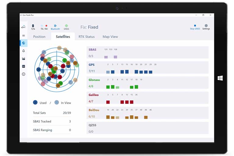
Eos Tools Pro for Windows shows all current satellites in use from GNSS constellations such as GPS, Galileo, BeiDou, GLONASS and QZSS. (Screenshot: Eos Positioning)
Geoid models. Eos Tools Pro implements the latest geoid models for many regions in the world, providing survey-grade orthometric heights directly into any Windows applications.
Datum shift. Eos Tools Pro adds a new feature to apply a simple X, Y, Z shift to the current location to match any local datum.
Alarms. A vast number of audible alarms can be set to warn the user if parameters such as estimated accuracy, differential status, correction age, Bluetooth connectivity, are not met.
For Windows developers
Geolocation/Sensor API. Eos Tools Pro supports apps that rely on the Windows geolocation service to retrieve accurate latitude, longitude and altitude from their Arrow receiver. In addition, the Sensor API allows programmers to access the wide array of GNSS metadata while removing the laborious task of parsing NMEA data.
Virtual COM port and TCP/IP server. Eos Tools Pro features a built-in duo of virtual COM port and TCP/IP server to output streams of standard NMEA sentences. This enables multiple apps capable of parsing NMEA messages to have simultaneous access to the Arrow GNSS location and metadata.
“Eos Tools Pro for Windows enables users and developers to benefit from our leading-edge, high-accuracy GNSS receivers,” Lauture said. “When Windows tablets are the device of choice among our customers, the combination of Eos Tools Pro and Arrow GNSS receivers provide the absolute latest GNSS technology for GIS, engineering, construction, and surveying users. When Windows tablets are the device of choice among our customers, the combination of Eos Tools Pro and Arrow GNSS receivers provide the absolute latest GNSS technology for GIS, engineering, construction and surveying users.”
Eos Tools Pro for Windows is available for free to users of Arrow GPS and GNSS receivers. It is compatible with any Windows 10 desktop, laptop or tablet computer via Bluetooth or USB.
Latest inertial navigation system serves new customer requirements in autonomous vehicles, mobile mapping, surveying and more
Photo: Honeywell
Honeywell is introducing the HGuide n380, an inertial navigation system (INS) that communicates position, orientation and velocity of an object — such as an autonomous vehicle or unmanned aerial vehicle (UAV) — even when global navigation satellite signals are unavailable.
Smaller, lighter and lower priced than previous Honeywell inertial navigation systems, the HGuide n380 is built using Honeywell’s rigorous design standards to withstand harsh environments in the air, on land or at sea.
“We recognized a need for a small, high-performance inertial navigation system in areas like 3D mapping, surveying and other applications where space is at a premium and performance cannot be compromised,” said Chris Lund, offering management senior director, Navigation and Sensors, Honeywell Aerospace. “We responded by developing the HGuide n380 inertial navigation system, which provides our customers with proven, cost effective inertial sensor technology, created for aerospace applications, but that can be integrated into almost any architecture.”
The new inertial navigation system is composed of Honeywell’s HGuide i300 inertial measurement unit (IMU), a GNSS receiver and Honeywell’s proprietary sensor-fusion software, which is based on the algorithms used for navigation on millions of aircraft every day.
Inputs from these components are fused together to determine position, orientation and velocity to deliver critical navigation information even in areas where a satellite signal is degraded or altogether unavailable, such as canyons, bridges, tunnels, mountains, parking garages or dense forests.
“As the industry evolves, Honeywell’s HGuide suite of IMUs and navigators will be a key enabler of emerging segments like autonomous vehicles, mobile mapping, precision agriculture, robotics and surveying,” Lund said.
During its development, the new product was placed in extreme environments to test ruggedness and was exposed to extensive factory calibration and compensation procedures that help ensure measurement accuracy and performance.
Honeywell has extensive experience in designing and building high-end inertial sensor and navigation systems and has used that expertise to develop a lower-cost portfolio of HGuide offerings to serve new markets and customer requirements.
To date, Honeywell has delivered more than half a million high-performance inertial sensors to serve as navigation aids on an extensive list of manned and unmanned vehicles, which include many air and spacecraft in use today.