Trimble continues to increase its footprint to deliver high-accuracy positioning correction services
Photo: Trimble
Trimble has acquired MidStates VRS, a network previously owned by Butler Machinery and Frontier Precision. The addition of the network, in North and South Dakota, increases the footprint of Trimble’s VRS Now GNSS corrections service to cover more than one million square miles in North America. Financial terms were not disclosed.
As part of an ongoing expansion strategy, the new coverage for the VRS Now subscription service helps users in more places achieve high-accuracy positioning to increase productivity, reduce operational costs and improve safety.
The correction service is designed for professionals in agriculture, geospatial and construction as well as emerging autonomous applications including lane-keeping for passenger vehicles, vehicle-to-everything (V2X) position identification and unmanned aerial system guidance.
Adding 105,000 square miles of coverage, the acquisition expands Trimble’s VRS Now network to be one of the largest in North America — over one million square miles, contributing to Trimble’s shift toward a software, services and subscription business emphasis.
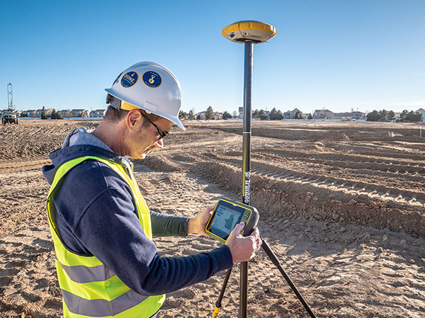
When using the Trimble VRS Now service, land and construction surveyors, GIS professionals and farmers — with a Trimble or third-party commercial GNSS receiver — can leverage instant high-accuracy corrections delivered via cellular network to improve productivity.
Enabling users to work without a GNSS base station, the service is cost-effective and simple to use. It is ideal for a variety of applications that require sub-inch level accuracy and is an important component of the connected construction site and connected farm workflows.
“The MidStates VRS network covers significant farmland, oil fields and rapidly developing urban areas, providing farmers and surveyors in the region with the real-time GNSS correction services they need to improve their day-to-day work,” said Patricia Boothe, senior vice president of Trimble’s Autonomy Sector. “The purchase of the MidStates network demonstrates Trimble’s ongoing commitment to provide a wide range of correction services for autonomous solutions — delivering unmatched access to fast, reliable and highly accurate positioning in more areas than ever before.”
Trimble networks are supported by a global network operations team made up of GNSS system engineers, geodesy experts and IT professionals. The team monitors the networks 24/7 from operation centers located on three continents, providing consistent and reliable service uptime and performance integrity.
Trimble VRS Now. The correction service offers instant access to centimeter-level positioning tailored to the users’ geographic location; the service is always on wherever and whenever needed within the network coverage area. With no base station or setup required, it is cost-effective, efficient and simple to use.
VRS provides positioning professionals with instant access to real-time kinematic (RTK) and post-processing (PP) corrections utilizing a network of permanent (fixed) continuously operating reference stations (CORS).
Trimble-owned VRS networks are accessible now in areas throughout the U.S. and Canada as well as Eastern Australia and Tasmania, France, Belgium, the Czech Republic, Estonia, Germany, Great Britain, Ireland, Luxembourg, the Netherlands, Sweden and New Zealand.
Auto Mining: A driverless Cat 793F CMD truck leaves an iron ore pit. (Photo: Caterpillar)
Individuals who use GNSS today may not know the significant advancements that have been accomplished over the past 30 years to obtain accurate GNSS-derived coordinates, especially GNSS-derived orthometric heights.
Thirty years ago, there were two limiting factors for estimating GNSS-derived heights — estimation of accurate ellipsoid heights in a timely manner and the availability of an accurate geoid model. The geoid model was only good to the decimeter level, between two stations relatively close together. A significant improvement of the measurement of the Earth’s gravity field (such as from the GRACE mission) and digital elevation data (from the Space Shuttle Radar Topography Mission) facilitated the creation of more accurate geoid models. Geoid models went from decimeter values to centimeter, and then sub-centimeter values between closely spaced marks.
A new national network
During the past three decades, the U.S. National Geodetic Survey (NGS) has developed a national network of Continuously Operating Reference Stations (CORS). These CORS, along with the states’ real-time networks (RTNs), have provided the ability to compute accurate GNSS-derived coordinates in an efficient and effective manner. The modeling of antenna phase patterns was a critical development for combining different types of antennas.
Today’s GNSS processing software is basically a “hands-off black-box” system. But 30 years ago, the analyst had to identify cycle slips and ensure that all unknown cycle ambiguities of the carrier-phase data (integers) were determined correctly. It was a time-consuming task, and analysts needed to understand the data. So many things can go wrong when someone relies on an answer from a black box. That said, federal agencies such as NGS and GNSS software companies have produced hands-off software that provides statistics and warning messages, as well as guidelines for ensuring results are consistent and accurate.
The advancements in estimating GNSS-derived coordinates (including orthometric heights) have changed the way many industries do business. Farmers use it to drive their tractors and combines, mining companies control driverless vehicles, construction companies use automated machine guidance to build roads, and, of course, it has improved how individuals navigate from one location to the next.
Hands-off farming and mining
Thirty years ago, few farmers thought they would be able to sit in their cab and let their combine harvester drive itself. Geodesist, surveyors, and engineers had a vision of using GNSS to automate the use of farming and construction equipment, which became a reality.
What will it be like in another 30 years? Will it be routine for individuals to program their car for a destination, and then sit back and read a book?
Positioning with GNSS will be critical for the safety factor of driverless vehicles and the use of drones for delivery. Geodesists, surveyors and engineers, once again, need to lead the way to meet the positioning requirements of the future.
The global construction robot market was valued at USD 231.5 million in 2018 and is expected to reach USD 464.8 million by 2026, growing at a compound annual growth rate (CAGR) of 9.5% during the forecast period, according to an InForGrowth market report.
The construction industry is one of the least automated industries that features manual-intensive labor as a primary source of productivity. However, with the advancement in technology, the construction industry is utilizing robots to excel at repetitive tasks in a controlled environment.
Construction robots have a major impact on the construction industry. The construction industry is looking to automate more and more tasks for the sake of productivity and efficiency, which in turn is increasing the demand for construction robots.
The use of robots has grown considerably with increasing speed, efficiency, safety and profit concerns. Construction robots have provided a transformative experience for the entire industry and have helped in replacing or improving existing processes, making them more proficient as well as more precise.
Companies are deploying these new commercially viable robots in various applications such as 3D printing of large structures, disaster relief situations, construction of tall structures, and for assisting workers performing laborious tasks. These robots have helped in automating laborious and dangerous tasks to keep laborers away from hazardous activities and enable them to focus on more productive work.
3D printing. Moreover, the evolution of 3D printing in the construction industry is expected to create opportunities in the market. This will further enhance the market size of the global construction robot market. An increase in research and development activities to minimize the cost of robots will also enhance the market size over the forecast period.
However, the high cost associated with the deployment of robotic solutions is expected to hamper the growth of the global construction robot market during the forecast period.
Key findings. Based on the product type, the traditional robot segment accounted for the largest market size in the global construction robot market in 2018.
Based on automation, the semi-autonomous robot segment accounted for the largest market size in the global construction robot market in 2018.
Based on function, the demolition robot segment held the largest share in the global market in 2018.
Based on applications, the public infrastructure segment is expected to dominate the market during the forecast period. Europe accounted for nearly 30% share of the global market in 2018.
Recent industry news. In September 2019, Built Robotics closed a US$ 33 million Series B funding round, led by Next47, the global venture fund backed by Siemens, for autonomous construction equipment.
In August 2019, John Sisk & Son used MULE at Sisk’s residential Wembley Park E05 site in London to reduce fatigue and injuries among workers and increase productivity.
In June 2019, Boston Dynamics launched an inspection robot named SPOT, which is mounted with 3D cameras to inspect and map construction sites and identify hazards and work progress.
Depending on your age, 30 years represents a varying opinion of time. For some, it may seem like forever; for others, it may be a blink of an eye. In respect to technology, it can represent a complete change in the way we do things.
When we turned the calendar page to January 1990, our world had yet to experience the internet, the Hubble telescope had not been deployed to share its fantastic views, and The Simpsons television series was preparing to become the cartoon juggernaut it remains today.
Yes, lots has changed since 1990, and surveying is no exception.
Most professions look back through their history and see various periods where discoveries and inventions revolutionized how the work was completed.
For surveyors, the past 30 years have contained more advancements than all other years combined, with the greatest achievement being the global navigation satellite system (GNSS). With the United States leading the way with its Global Positioning System and the civilian ability to use this measuring system, modern surveying was forever changed.
Solar and lunar observations replaced
Before the implementation of a satellite navigation system, true global navigation was only computed using solar and lunar readings under specific conditions. GPS provided a new frontier for surveyors to establish positions without having to perform traversing from known points or collecting solar/lunar observations.
As the constellation grew, it became easier to use GPS to gain initialization for accurate and redundant position determination. As processor speeds and data storage capability increased, real-time kinematic (RTK) observations became the norm for surveyors everywhere.
The Russian satellite constellation, GLONASS, began operating fully in the late 1990s, and is now included to create today’s GNSS. More satellites provide more coverage, which in turn means more data collection potential.
Many nations and regions are building their own constellations to augment the current GNSS lineup, and also to safeguard the ability to obtain geographic locations when other systems are not available.
Bathymetric surveys made easy
GNSS capability and integration revolutionized several aspects of surveying, including a new and more reliable way of performing bathymetric surveys over large bodies of water. Computerized depth sounders were programmed to coincide readings with GNSS data collection to provide a more accurate and precise method of hydrographic surveying.
The past decade has continued the reliance on GNSS technology with many more devices and applications — not just for the surveyor, but for the public as well. While surveyors are using GNSS receivers on unmanned vehicles such as UAVs and boats, satellite navigation has infiltrated into many of our everyday routines. Cellphones, fitness trackers and our automobiles use this technology to guide us to our destinations.
Surveyors have used the GNSS revolution to create a digital world for better data collection, asset management and increased efficiency. Much has changed in 30 years for the surveyor and the world around us, so we should not be surprised about what technology will bring us next.
Our ongoing battle with COVID-19 has shown we can adapt to radical changes. A big, but worthwhile, change would be to convert our existing land databases to a cadastre system.
Any place that one may travel around the globe, they will find boundary lines that define properties and regions. For some countries, these parcels may be primarily owned by the government while in more developed nations, a large percent of the land is owned by private citizens.
These parcels, when looked at together, together create a large jigsaw puzzle that seemingly fits together perfectly. Visually, all the lines should fit snugly to their adjacent neighbor so that the sum of the parts equals the whole. This system, called a cadastre, has many redeeming qualities and makes for an efficient choice of keeping an inventory of a region or country’s parcels and infrastructure.
Origins of the cadastre system
The cadastre system of parcel registration is the database of choice for determining land ownership and taxes on property through much of the developed world. Most of the places where this system of parcel registry consists of centralized governments usually have more oversight and legislative power than more “free” countries like the United States.
Also, these countries in which these systems exist are typically small and/or have a manageable number of parcels so the development of the cadastre is much more controlled and maintained.
To help us understand the origin of this parcel system, let us explore the background of cadastre and its beginnings:
Definition: an official register of the quantity, value, and ownership of real estate used in apportioning taxes Origin: Mid-19th century from French, from cadastre ‘register of property’, from Provençal cadastro, from Italian catastro (earlier catastico), from late Greek katastikhon ‘list, register’, from kata stikhon ‘line by line’. (Source: Merriam-Webster.com)
In the years after the fall of the Roman Empire and through the end of many feudal societies, land ownership was transferred to individuals and families with the expectation of paying a tax to the government for this opportunity. Landowners could plant and harvest their own crops, raise farm animals for labor, and provide various goods and services to the community.
Besides a small fee for conveyance, the government would ask for a “meager” tax to be paid regularly. Land that was sold to these individuals was recorded in a “cadastre” for tracking of ownership and tax payment. These records were primitive in nature and relied heavily on associating a parcel number to the owner versus an actual legal description to describe the property.
It was not until more sophisticated and elaborate surveying instruments were developed that physical descriptions of the land were used to determine boundaries.
Cadastre system gives way to legal descriptions
This cadastre system of parcel management continues to exist in modern times in many parts of the world with one notable exception: The United States. Some will equate our parcel indexing system as being a traditional cadastre, but this numbering procedure is secondary to the means and methods of parcel conveyance in the U.S.
For the non-surveyor reader, in the U.S. over the past few centuries a multitude of land systems have been used to establish parcel boundaries , each with their own unique system of describing land and conveyances. These types of land transactions began after the establishment of the colonial states and rapid expansion into previously unmapped territories.
The push westward across the country introduced the Public Land Survey System (originated by Thomas Jefferson) and established sectional land divisions. As we encountered (and acquired) new territories, including the Louisiana Purchase and Texas, existing land measuring units and description methods were maintained to preserve these systems. No matter how the parcels are described, we rely heavily on the grantor/grantee system of transfer of ownership and rights throughout most of the country, with parcel numbering being applied post-transaction.
So why is the grantor/grantee system the weak link in the chain of parcel establishment and conveyance? Many times, it comes down to the legal description and how it was created. Our system allows for the creation of a parcel by varying means by the professional land surveyor. The biggest issues occur when parcels are defined by a metes and bounds description with little to no reference to adjoining property or known monuments.
When the legal descriptions of these parcels come into play, that is when the trouble starts, with calls made to attorneys and surveyors to help straighten everything out. To the common layperson who owns land or is looking to buy a parcel, it may seem unthinkable that parcels do not naturally fit seamlessly together with no gaps or overlaps. While the quality of survey data has increased in precision, the accuracy of marrying old data with the new suffers in many ways. How did we get to this point? Let us step back in the not-so-distant past to review how things have progressed throughout my short career.
Set the flux capacitor to the early 1980s…
Before computers and CAD, most agencies adopted a system of parcel and right-of-way mapping manually drafted on large sheets of durable paper or film. Depending on the municipality or county one was in, each sheet could represent either a quarter section (approximately 160 acres) or one half of a quarter section (approximately 80 acres) within a standard section of the Public Land Survey System (PLSS) established by the General Land Office (GLO) of the U.S. (now known as the Bureau of Land Management).
These maps were based upon standard measurements within the given quarter section and drawn using 90-degree corners at the edges of the sheet. The linework depicting the parcels within blocks and larger areas was drawn as close to scale as possible but was intended to be a graphic representation of the shape rather than an accurate reproduction. Considering the technology and measuring devices/capabilities of the time, these records were very helpful in performing retracement surveys of existing properties.
Because these surveys and parcel recordkeeping were performed long before computers, plotters, and CAD software became the norm, surveyors calculated and documented their work using manual computation and drafting from handwritten notes collected in the field. Not every parcel has 90-degree corners and lengths that are integers, so mapping departments for governmental agencies drafted new surveys and parcel boundaries to fit within the existing base sheets. Throw in the varying measurements from different surveyors and we have the real-life jigsaw puzzle that does not fit.
Because the aforesaid mapping departments produced parcel numbering after the creation and conveyance of the property, the damage is already done in conforming with adjacent properties. This is an important factor in the professional surveyor’s responsibility to protect the public when performing an original survey for a new parcel and/or subdivision and utmost care must be observed.
We have an army of land surveyors across the country shaping parcels to fit within a large jigsaw puzzle with an instruction sheet that must be strictly followed. One missed measurement or corner monument is in the wrong position, and we now have two or more parcels that will not fit together in the puzzle.
Many mapping professionals will point, however, to the geographical information system (GIS) and how it improved this convoluted method of parcel databases. But did it?
The digital spaghetti bowl
For a large part of the U.S. where a data-intensive GIS has been created and maintained, it is a step in the right direction, but it still lacks the overall efficiency of a cadastre. Very few GIS databases contain survey-grade parcel establishment on recognized horizontal and vertical datums. Most are parcels and roadways digitized from old mapping and records that are vague graphical representations at best.
One of the most important pieces of the GIS database are the base layers that contain control points and parcel/right-of-way lines that coincide with the datums that govern the region or state. Many governmental agencies do not employ a professional surveyor or surveying staff educated and trained to establish these datums within the database.
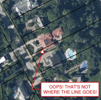
Incorrect GIS parcels information. (Image: Tim Burch)
Most times, the base layers are established “close enough” using aerial mapping and other data, including handheld GNSS receivers to collect infrastructure improvements. This is not a knock on these departments or individuals; they created the best possible database with the information on hand.
When merged with aerial mapping and/or survey-grade data, the graphical information from the archival records can be confusing and misleading, especially to those who are not educated to understand the data.
Is the cadastre an upgrade?
The reason to consider converting all the existing parcel mapping and subsequent infrastructure/improvement mapping to a cadastre are simple: technology. We have previously discussed cities building digital twins (“Surveying and Geospatial Data,” GPS World, July 2020) utilizing remote sensing and a multitude of GNSS-capable products.
Besides surveyors, many professions and trades use GNSS technology as a tool within their work environments. Our nation has experienced rapid growth in the last 150 years. The Industrial Revolution and the advancement of machinery, materials and building techniques have greatly impacted the ability to build more infrastructure and improvements. Many of these improvements and utilities have exceeded their useful life but have no timelines for replacement.
Developing accurate maps of this aging infrastructure will ensure a proper data set from which a replacement design can be made. Couple this ability to work in a geospatial environment with other datasets, including aerial/satellite photography and lidar acquisition, and it gives us a nearly unlimited ability to map our world in appropriate datums with greater accuracy and precision. Governmental agencies could utilize this system to monitor illegal activities (such as dumping, mining, unpermitted construction) and gauge environmental concerns (drainage issues, problematic runoff, deteriorating infrastructure) to better protect the public. This system could also be used to refine our property tax system and work towards a more equitable means of assessing our properties.
None of these potential changes and upgrades would have been possible 40-50 years ago; the invention and adaptation of GNSS have allowed these technologies to emerge. We continue to find new ways of measuring and mapping, so using these new techniques should be foremost on our minds to make these previous tedious tasks much easier to accomplish.
The hurdles to change
The biggest challenge, in my professional surveying opinion, will be adapting millions of parcels and deeds to a new database and applying them to the current datums. For instance, here is an example of potential (and recordable!) legal description:
“Beginning at the northeast corner of the parcel, said corner being the intersection of the south right-of-way line of Smith Street with the east right-of-way line of Jones Street; thence easterly on the said south line of Smith Street to the northwest corner of the Williams parcel per Deed No. 12345; thence southerly on the west line of said Williams parcel to the north right-of-way line of Main Street; thence westerly on the said north line of Main Street to the intersection with the said east right-of-way line of Jones Street; thence north on the said east right-of-way line of Jones Street to the point of beginning.”
Example of “bounds” legal description. (Image: Tim Burch)
While this is only a made-up example, it does represent a generally accepted legal description for parcel conveyance in most recording agencies. What does a mapping department do with this kind of legal description to place it accurately within a GIS or cadastre? Unless the four adjoining legal entities (Smith Street, Jones Street, Main Street, and the Williams parcel) exist geospatially within the database, the technician will have a tough time inserting this parcel into the records. Unless the entire surveying community is up to the challenge of working solely in an approved geospatial datum for all their work, much of this effort will not accomplish anything.
The other roadblock to converting our current systems to a cadastre is the rest of the parties who work with legal documents, plats, and infrastructure; they may not be up to the challenge for making a radical change for the better. From the assessor’s, recorder’s, and mapping offices to the title companies and attorneys, many have an attitude that the system is too big to revamp. Because they only work in one part of the overall system, they do not see the benefit of blowing it all up to make it a more robust and useful database.
Practically speaking…
Revamping of any system within the varying levels of government is costly, no matter what branch or region is discussed. Governmental agencies are being asked every day to do more with less and provide more value in their services with few numbers of staff.
While there may be a large upside to converting our existing databases to a cadastre, the downside is the effort and cost to do so. Yes, the new system would be scalable and easily adaptable for more infrastructure growth and could be expanded in an infinite number of ways. We can liken this proposed idea to converting all weights and measures to the Metric System: going metric will make lots of tasks and procedures easier, but flies in the face of everything we know as a society.
However, our ongoing battle with COVID-19 has shown we can adapt to radical changes. The cadastre is a better system, but I do not want another worldwide disaster to convince us to change.
Tilt compensation to increase productivity for land surveyors
Trimble has introduced the Trimble R12i GNSS receiver, the latest addition to its GNSS portfolio. The Trimble R12i incorporates inertial measurement unit (IMU)-based tilt compensation using Trimble TIP technology, which enables points to be measured or staked out while the survey rod is tilted.
The tilt function is designed to empower land surveyors to focus on the job at hand and complete work faster and more accurately.
The IMU-based tilt compensation capability of the Trimble R12i builds on Trimble’s unrivaled ProPoint GNSS positioning engine, which delivers more than 30 percent better performance in challenging environments compared to the Trimble R10-2 receiver across a variety of factors, including time to achieve survey precision levels, position accuracy and measurement reliability.
Designed with flexible signal management that enables the use of all available GNSS constellations and signals, the Trimble ProPoint GNSS engine provides new levels of reliability and productivity.
Photo: Trimble
In addition, the ProPoint engine is a key enabler of the new TIP technology. Surveyors can continue to use the R12i’s tilt compensation functionality even in challenging environments when other solutions struggle to maintain GNSS and inertial positioning.
The Trimble TIP technology allows users to accurately mark and measure points in areas previously inaccessible for GNSS rovers such as building corners, or in hazardous situations, for example the edge of an open excavation. The receiver operates calibration-free out of the box and is resistant to magnetic interference from sources such as cars or electrical utility boxes.
The R12i also features real-time automatic inertial navigation system (INS) integrity monitoring. This system allows users to detect and correct for IMU biases introduced by use over time, temperature or physical shocks helping ensure measurement quality and integrity for the life of the receiver.
“The R12i represents Trimble’s dedication to perfecting the user experience with the industry’s best GNSS engine and now robust tilt compensation,” said Ron Bisio, senior vice president of Trimble Geospatial. “Trimble has been the leader in GNSS technology for more than 30 years and the R12i demonstrates our continued commitment to providing surveyors with the world’s most advanced and trusted GNSS systems.”
The Trimble R12i GNSS System is available now through Trimble’s Geospatial distribution channel.
A roundup of recent products in the GNSS and inertial positioning industry from the September 2020 issue of GPS World magazine.
OEM
Inertial sensors
Includes four models
Photo: SGB Systems
The third-generation Ellipse series has a 64-bit architecture, allowing high-precision signal processing. All of the INS/GNSS devices now embed a dual-frequency, quad-constellation GNSS receiver for centimetric position and higher orientation accuracy. The Ellipse-A is a motion sensor; Ellipse-E provides navigation with an external GNSS receiver; Ellipse-N is a single-antenna RTK GNSS/INS; and Ellipse-D is a dual-antenna RTK GNSS/INS. With its new 64-bit architecture, the third-generation Ellipse series enables the use of high-precision algorithms and technology used in high-end inertial systems such as rejection filters and FIR filtering.
The PNT-6220 Assured Reference combines low-Earth-orbit (LEO) signals, GNSS, terrestrial, wireline and atomic clock services in one small solution for critical infrastructure applications. The PNT-6220 seamlessly combines concurrent L1, L2, L3 and L5 GNSS reception with a LEO-based Satellite Time and Location (STL) timing receiver. It also includes terrestrial receivers and PTP/IEEE-1588 edge grandmaster and PTP/IEEE-1588-slave capability. It provides assured PNT for critical infrastructure applications such as those described in the directives of Presidential Executive Order 13905. It can serve as a timing reference for 5G equipment, an ePRTC-capable reference, or a high-performance disciplined reference that supports PTP/IEEE-1588, STL, RF distribution and multi-frequency GNSS capability. The PNT-6220 can automatically select the most optimal UTC reference input and switch over among its numerous reference inputs if one or more are jammed or spoofed, as well as average several references for additional stability and accuracy.
Jackson Labs Technologies, jackson-labs.com
GNSS Receiver
Integrates correction service
Photo: Septentrio
The AsteRx-m2 Sx OEM board provides a GPS/GNSS receiver with always-on sub-decimeter accuracy without the need for additional correction service subscriptions. GNSS corrections are automatically streamed to the receiver. The integration enables plug-and-play positioning with high accuracy available out of the box. The AsteRx-m2 Sx is an efficient positioning solution for small robots, aerial drones and automation applications. Advanced anti-jamming technology AIM+ ensures robust and reliable operation in challenging environments, even in the presence of RF interference.
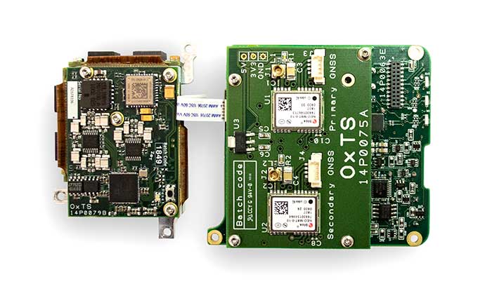
The xOEM v3 inertial navigation system includes the architecture from the company’s IP65-encased xNAV v3 as well as a full range of software interfaces, providing integrators maximum configuration flexibility, real-time monitoring, post-processing and analysis. Software interfaces can be customized using the OxTS NAVsuite. Plugins can be created using the company’s NAVsdk, allowing the xOEM v3’s software to be easily packaged and included as part of a product.The high-grade MEMS inertial sensors and real-time kinematic (RTK)-capable GNSS receiver within the xOEM v3 board set deliver high performance capabilities. The board set provides 0.1° heading accuracy, 0.05° pitch/roll accuracy and 2 cm global position accuracy. The board set is compact at 150 grams, which enables manufacturers to seamlessly integrate and build a high-performance INS into their products, such as commercial mapping applications on land and in the air. Its light weight means more payload capacity for other critical components. An add-on lidar georeferencing software package is also available with a sophisticated boresight calibration tool.
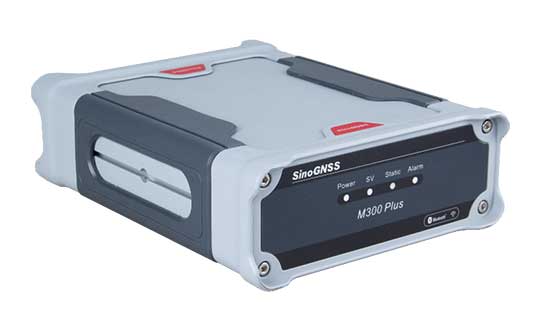
The M300 Plus GNSS receiver is designed to supplement the company’s M300 Pro, which is aimed at clients who need a more economical version for their CORS networks. The M300 Plus is also designed for monitoring projects and other applications. By using a powerful, adaptive detecting and canceling technology, the M300 Plus provides enhanced anti-jamming capability, which is critical for a reference station providing reliable GNSS data. Its built-in web server provides remote control of receiver configuration, status, firmware update and data download. It uses a 4G module as an internet backup, enhancing the stability of data connections.
The MQ-8 family — 3D lidar sensors and perception software — are part of Quanergy’s Flow Management platform. Designed with a new smart beam configuration, the MQ-8 solution delivers up to 140 meters of continuous tracking range, enabling up to 15,000 m2 of coverage with a single sensor. It is suitable for flow management applications such as security, smart city, social distancing and smart space industries.
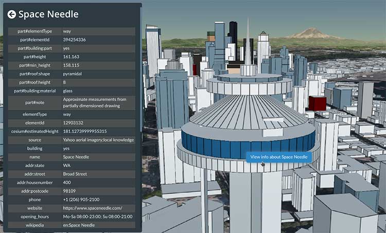
Cesium OSM Buildings expands the company’s suite of Global Base Layers including worldwide terrain, aerial imagery and streetmaps already available. With the new layer, 3D buildings can be visualized, styled and analyzed in an efficient and interoperable manner using 3D Tiles, the open standard developed by Cesium to stream massive 3D geospatial datasets. The layer gives geospatial developers urban context to 3D applications. The buildings are created for efficient visualization and are streamable to any device with 3D Tiles.Cesium OSM Buildings are derived from OpenStreetMap. Buildings are also regularly updated, firmly clamped to terrain, and individually selectable and styleable.
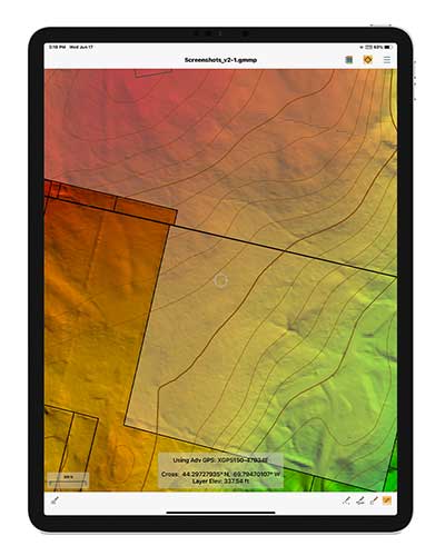
Version 2.1 of Global Mapper Mobile provides updates to both the free and Pro versions. The iOS and Android applications are designed for viewing and collecting GIS data, and provide situational awareness and location intelligence for remote mapping projects. A complement to the desktop version, the mobile app can display all supported vector, raster and elevation data formats. The release improves vector feature styling, terrain layer support and layer transparency setting. In the Pro version, it introduces advanced GPS support, allowing users to connect to external, high-accuracy Bluetooth GPS devices from vendors such as Eos Positioning and Bad Elf. It also allows access to detailed information including the satellite constellation, precise location information and the raw NMEA stream.
The AiRXOS Enterprise Energy Solution provides digital compliance, situational awareness of airspace and assets, inspection, emergency response/disaster recovery capabilities, analytics and asset performance tools in a connected platform. It runs on AiRXOS’ Air Mobility Platform — a secure, cloud-based, extensible platform that enables integration of an energy organization’s current applications and other UAS service suppliers. It brings all UAS lifecycle operations into one view, including infrastructure inspection, asset and crew management, and emergency operations after a natural disaster.
The Xeno FX is a fixed-wing platform optimized for efficient and cost-effective area survey and monitoring missions. Users can program the flight plan before launch to ensure thorough coverage of a target region. The fixed-wing design allows for efficient cruise and maximum time aloft. The Safe Launch protective feature means the propeller starts spinning only after the airframe has been safely hand launched. A quick-change modular payload system allows users to reconfigure their data-acquisition hardware for multiple missions. Constructed of Multiplex’s resilient Elapor foam, the folding wings make for compact storage and easy transport.
Hexagon AB has introduced the Leica GS18 I, a versatile, survey-grade GNSS RTK rover so powerful it enables surveyors to measure what they see, even structure in difficult-to-reach places, the company said.
It comes equipped with all the innovative functionality of the Leica GS18 T — Hexagon’s calibration-free, tilt-compensating GNSS solution immune to magnetic disturbances, plus the power of survey-grade visual positioning.
Through sensor fusion of GNSS, motion (IMU) and image (camera) technology, the Leica GS18 I enables the measurement of points from images. The ability to capture and measure sites via images goes far beyond the advantages of the GS18 T, which introduced the quick and convenient ability to measure points in spaces that cannot be measured with vertical poles, such as building corners, walls and points underneath obstacles (for instance, cars).
With the Leica GS18 I, professionals can now map areas that are difficult to reach physically, such as trenches, high power lines and busy roads, or blocked from GNSS signals, such as areas underneath bridges or canopies — safely and effortlessly from a distance.
“With the Leica GS18 I, mapping and surveying just got simpler, safer and more productive than ever before,” said Ola Rollén, Hexagon president and CEO. “The ability to quickly document an entire area of interest without the need to switch between tools or manoeuvre through obstacles frees up equipment and crews. Additionally, the simple and intuitive workflow of the Leica GS18 I brings the versatility of visual positioning to new user segments and applications — from utility service providers to crash scene investigators.”
The Leica GS18 I enables users to measure hundreds of points within minutes. Integration with Leica Captivate field software enables intuitive onsite point measurements and quality assurance from the field.
Further measurement of the captured images is supported by integration with Leica Infinity office software, which also enables the creation of automatically registered and referenced 3D point clouds from the images in standard export formats for use in a variety of point cloud software.
Carlson Software is now offering its next-generation multi-frequency, multi-GNSS BRx7 smart antenna.
The BRx7 is a full redesign of Carlson’s flagship GNSS receiver, delivering high-level specifications, performance and value for surveyors, contractors, engineers and GIS professionals.
Weighing 2.8 pounds with batteries, the BRx7 saves time and increases productivity by accurately compensating for tilt. It comes standard with dual, hot-swappable batteries for 11+ hours of uninterrupted efficiency. The BRx7 provides 800+ channels, 8gb of memory, and is designed with a rugged, compact IP67-rated housing.
Best-in-class RTK performance is provided by the Athena GNSS engine, supporting multi-frequency GPS, GLONASS, BeiDou, Galileo, QZSS, IRNSS and Atlas L-band capability. In addition, the BRx7 uses proprietary SureFix technology to provide a high-fidelity quality indicator of the RTK solution, allowing users an extremely high confidence in their current accuracy.
The BRx7 provides RTK baselines up to 50 km with fast acquisition times when used with Carlson Listen-Listen, as well as UHF, spread spectrum, cellular, Bluetooth and Wi-Fi wireless communication.
Well-suited to a variety of operating modes, the BRx7 can be deployed as a powerful base with additional access to BeiDou phase 3 satellites in a base-rover setup, or as a lightweight, powerful network rover.
“The BRx7 represents the next generation of GNSS technology,” said Butch Herter, Carlson’s director of hardware development. “Through this total redesign in partnership with our manufacturer, Hemisphere GNSS, we’ve brought the technology and functionality above the competition while retaining the ease-of-use, durability, and superior support that Carlson is known for.”
The smart antenna comes with a dual-band radio module that is capable of both 400 MHz and 900 MHz operation. This allows for the long range capability of the UHF 400 MHz signal plus the ability to switch to the 900 MHz frequency-hopping spread spectrum (FHSS) signal for better performance in noisy radio environments.
The BRx7 introduces a new INS-based sensor-fusion platform to support enhanced tilted pole measurements for land survey applications. This new design allows for easy calibration, is immune to magnetic interference, and is extremely reliable in virtually any environment.
“The BRx7 represents the advanced technology, durability, and ease-of-use that our customers have come to expect,” said Bruce Carlson, founder and president of Carlson Software. “By redesigning this system from the ground up, we are offering our customers both unparalleled performance and versatility, but also a value that’s unbeatable in the market today.”
Tallysman Wireless Inc. has added four embedded VeroStar products to its line of GNSS antennas. The compact and light embedded VeroStar models offer key features not available in many other embedded antennas on the market.
Photo: Tallysman
The VSE6028, VSE6028L, VSE6328 and VSE6328L embedded VeroStar antennas are designed and crafted for high-accuracy positioning. With an exceptionally low roll-off from zenith to the horizon, VeroStar antennas provide tracking of GNSS and L-band correction signals at low elevation angles.
The optimized axial ratio at all elevation angles results in excellent multipath rejection, enabling accurate and precise code and phase tracking.
For details on the antenna and its development, see “Innovation” in the September issue.
VeroStar antennas feature a robust pre-filter and high-IP3 LNA architecture, minimizing de-sensing from high-level out-of-band signals, including 700 MHz LTE, while still providing a noise figure of only 1.8 dB.
Photo: Tallysman
The light (80 g) and compact (106 mm in diameter and 40 mm in height) wide-band spherical antenna element enables the VeroStar to deliver a ±2 mm phase centre variation (PCV), making it ideal for high-precision applications, such as autonomous vehicle navigation (land, sea and air), smart survey devices, and maritime positioning.
The VSE6028 supports the full GNSS spectrum (the VSE6028L includes support for L-band correction services), while the VSE6328 supports the GPS/QZSS-L1/L2/L5, GLONASS-G1/G2/G3, Galileo-E1/E5a/E5b, BeiDou-B1/B2/B2a, and NavIC-L5 signals and frequency bands (the VSE6328L includes support for L-band correction services).
The unique features of the VeroStar antennas deliver high signal-to-noise ratio (SNR), high accuracy, and high precision in challenging environments.
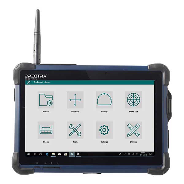
Spectra Geospatial is partnering with Aplitop for a comprehensive tunnel survey solution designed to increase productivity for survey service providers.
According to the companies, the collaboration provides surveyors and geospatial professionals with a complete hardware and software solution for performing efficient tunnel construction surveys.
Through the partnership, the Spectra Focus 35 robotic total station will be integrated with the workflows of the Aplitop TcpTUNNEL, running on the ST10 or Ranger 7 data collector. This will enable surveyors to perform excavation control, automated survey and stakeout of tunnel cross-sections, the companies said.
In the office, data and designs can be transferred seamlessly between TcpTUNNEL CAD, a plug-in for several CAD platforms, and TcpTUNNEL field software.
The Spectra Geospatial and Aplitop solution provides a full featured workflow for tunnel constructions surveys including definition of project design elements; tunnel drill and blast setout and reporting on the difference; automated data collection; accurate stake-out-of-key design features and anchor belts; and graphical reporting of the differences between design and survey data.
“Collaborating with Aplitop enables Spectra Geospatial to provide customers with a world-class tunneling solution to increase productivity working in underground environments,” said Olivier Casabianca, vice president at Spectra Geospatial. “The combination improves the tunnel construction process by providing customers with increased confidence in the field and streamlining final deliverable creation in the office.”
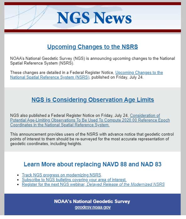
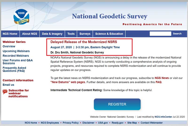
The National Geodetic Survey (NGS) recently announced two new items related to the modernized National Spatial Reference System (NSRS). First, it announced that there will be a delayed release of the modernized National Spatial Reference System (NSRS). See the box titled “Updates notices from NGS Homepage” for the link to the notice.
The box titled “Delayed Release of the Modernized NSRS” provides a summary of the notice. The announcement stated they are performing a thorough review of all tasks and will provide regular updates on their progress. What this means is that the modernized NSRS will not be completed by 2022. Even if it’s delayed a couple of years, it’s never too early to obtain an understanding of the new, modernized NSRS, and start preparing for the transition to the new NSRS.
NOAA’s National Geodetic Survey (NGS) is announcing a delay in the release of the modernized National Spatial Reference System (NSRS).
In 2007, NGS began planning for the modernized NSRS, acquiring its first airborne gravimeter, creating and initiating the Gravity for the Redefinition of the American Vertical Datum (GRAV-D) project and by 2008 had codified its modernization plans into a Ten Year Plan. At that time, the target completion date was 2018. By 2013, that date seemed unlikely, due to both the broadening of the GRAV-D coverage area and the experience of five years of operational planning and execution.
In 2013, NGS revised its 2008 Plan, and targeted 2022 as the date of the release of the modernized NSRS. This date was reinforced with a 2018 Strategic Plan revision. By 2017, confidence in hitting the 2022 target was high enough to reach final agreement with Canada and Mexico on a naming convention for certain components, to include “2022” in their names.
Since 2017, operational, workforce, and other issues have arisen and compounded, causing NGS to recently re-evaluate whether a successful roll-out by 2022 is possible. The most significant impacts have been in workforce hiring and retention, and in meeting GRAV-D data collection milestones, which underpin the NSRS modernization efforts.
NGS is currently conducting a comprehensive analysis of ongoing projects, programs and resources required to complete NSRS modernization and will continue to provide regular updates on our progress. To get the latest news on NSRS modernization and track our progress, subscribe to NGS News or visit our “New Datums” web pages.
The second important announcement by NGS was that two Federal Register Notices related to the modernized NSRS were published on July 24. See the box titled “NGS News.”
Image: National Geodetic Survey
The first Federal notice was titled “Upcoming Changes to the National Spatial Reference System.” See the box titled “Federal Register Notice titled Upcoming Changes to the National Spatial Reference System” for the summary. This announcement provides a statement about the new, modernized NSRS and that it’s going to be published between 2022 and 2025. The information about the modernized NSRS shouldn’t be new to anyone that’s been reading my newsletters, but the Federal Notice makes it official and NGS provides dates of when the modernization will be rolled out.
Federal Register Notice titled “Upcoming Changes to the National Spatial Reference System”
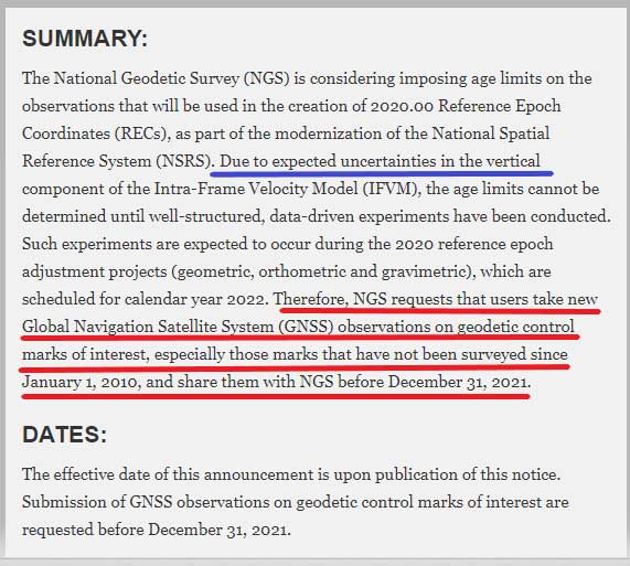
The second Federal Notice was titled “Consideration of Potential Age Limiting Observations To Be Used To Compute 2020.00 Reference Epoch Coordinates in the National Spatial Reference System.” This is a very important notice that users of NGS published coordinates should read and understand. NGS is considering imposing data age limits that will be part of the new, modernized NSRS. See the box titled “Imposing Age Limits of Data in 2022” for a summary of the Federal Register Notice announcement.
My last column highlighted that in the modernized NSRS the only way to get “into the datum” will be through a GNSS survey. It noted that leveling projects generate relative height differences not absolute heights. It emphasized that in the new modernized, time-dependent NSRS, the absolute height will be provided by up-to-date GNSS data; and the relative height differences between leveling marks will be provided by the leveling data. Many of my previous newsletters have explained different aspects of the new NSRS and how it may affect the surveying and mapping community products and services. As the Federal Register Notice implied, at this moment, NGS expects large uncertainties in the vertical component of the Intra-Frame Velocity Model (IFVM) which will translate into the GNSS-derived height Limiting the age of data will help to reduce the amount of uncertainty in the vertical component based on older data. Saying that, this could have an impact on users that rely on coordinates established using data acquired prior to 2010. NGS is requesting that users take new GNSS observations on all stations of interest that haven’t been occupied since the year 2010. The supplementary information in the Federal Register notice contains some very important statements. I have highlighted several statements in the box titled “Supplementary Information from Imposing Age Limits of Data in 2022.”
NGS hasn’t decided on the date of the age limit but the notice states that “For instance, it is unlikely that such an age-limit will be fewer than 10 years.” This is why NGS recommends the following “that users take new GNSS observations on geodetic control marks of interest that have not been surveyed since January 1, 2010, and asks the users to submit the observations to NGS before December 31, 2021.” Another important item in the supplemental information section is that NGS is enhancing the OPUS-Projects tool to include real-time kinematic and real-time network (RTK/RTN) observations. This should help to facilitate users submitting data on marks of interest so that they will have 2020.0 Reference Epoch Coordinates (REC).
Supplementary Information from Imposing Age Limits of Data in 2022
SUPPLEMENTARY INFORMATION:
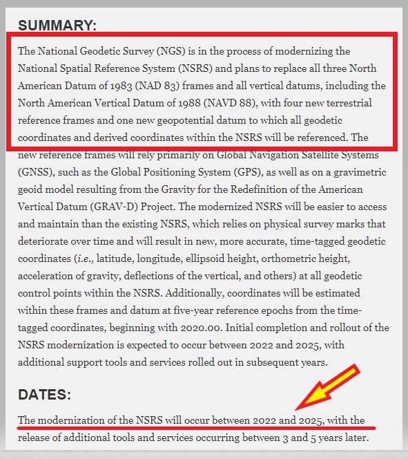
In 2017, the National Geodetic Survey (NGS) announced its plans to estimate RECs on a five-year cycle in NOAA Technical Report NOS NGS 67, 2019, starting with the first reference epoch at 2020.00, as part of the modernization of the NSRS. In the Technical Report, the exact observations to be used for this estimation were listed as “To Be Determined.” NGS is considering imposing age limits upon the observations that will be used, particularly because of expected uncertainties in the vertical component of the IFVM. These age limits cannot be determined until additional well-structured, data-driven experiments are conducted. Such experiments are expected to occur during the 2020 reference epoch adjustment projects (geometric, orthometric, and gravimetric), which are scheduled for calendar year 2022.
However, since the cut-off for new observations to enter those adjustment projects is December 31, 2021, any decision to age-limit input observations will come too late for submissions to impact the 2020 RECs. While the cut-off for age-limited observations is unknown, certain assumptions are safe to make. For instance, it is unlikely that such an age-limit will be fewer than 10 years. Older observations may be used in the estimation of 2020 RECs, but this cannot be guaranteed. As such, NGS requests that users take new GNSS observations on geodetic control marks of interest that have not been surveyed since January 1, 2010, and asks the users to submit the observations to NGS before December 31, 2021. Users may either (a) submit existing unsubmitted observations through the OPUS-Share tool or (b) conduct new GNSS observations and submit the data to NGS via the OPUS-Share tool.
In order to increase the submission of GNSS observations on marks, NGS is prioritizing the finalization of an expanded OPUS-Projects tool, which will allow real-time kinematic and real time network (RTK/RTN) observations to be submitted, rather than the standard four-hour observations required in OPUS-Share. Initial roll-out of this new tool is expected to occur during calendar year 2020.
This action is designed to increase both the number and the coordinate accuracy of geodetic control points, which in the modernized NSRS will have an estimated 2020.00 REC. Historically, NGS has combined data across multiple decades to estimate geodetic coordinates, yet such efforts have not fully accounted for the lack of information about vertical motion of geodetic control points throughout the years. Since height information is critical to the understanding of floods, failure to compute heights accurately can have negative impacts on property and lives. NGS views periodic re-surveys of geodetic control points, rather than the estimation of coordinates from observations that are years (or even decades) old, as the most effective way to maintain accurate and up-to-date knowledge of geodetic coordinates, including heights. As such, this announcement provides users of the NSRS with advance notice that geodetic control points of interest to them should be re-surveyed for the most accurate representation of geodetic coordinates, including heights.
NGS has scheduled a webinar for August 27, 2020, to discuss the delayed release of the modernized NSRS. See the box titled “Webinar on Delayed Release of the Modernized NSRS” for the announcement and web link to register for the webinar. I would encourage all users of the NSRS to register for this webinar.
Many users are probably wondering if the delay in the new, modernized NSRS will change the dates of other deadlines. The FAQs webpage addresses some of these questions. I have highlighted a few FAQs in the box titled “Questions from NGS FAQ Website.”
How will the delay affect the GPS on Benchmarks Phase II deadlines?
The deadline for submittal of GPSonBM data for the 2022 Transformation tool will remain December 31, 2021
If SPCS2022 zone designs are completed before other parts of NSRS modernization, will SPCS2022 be released sooner?
No. SPCS2022 is explicitly defined with respect the four 2022 terrestrial reference frames (not NAD 83), and SPCS2022 will be released along with the roll-out of those frames. If the frames are rolled out prior to other parts of the NSRS modernization, the frames will be accompanied by SPCS2022 (see the previous FAQ about phased roll-outs).
However, complete definitions of all SPCS2022 zones will be made available as soon as they are finalized. NGS expects that to occur by the end of 2021. Providing zone definitions early will give software vendors, database administrators, and others ample time to adopt and test them in their systems. Doing so will ensure SPCS2022 is available for immediate use upon roll-out of the 2022 terrestrial reference frames.
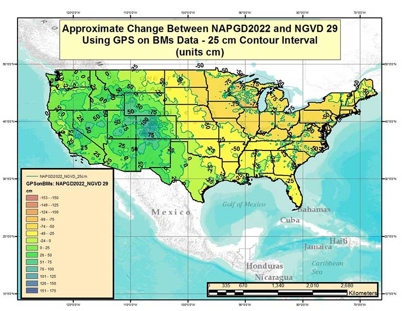
My projected height change seems to return me to NGVD 29 heights. Is this a coincidence?
This is coincidental. It so happens that, in some areas of the country the actual orthometric height in a region happens to be numerically closer to NGVD 29 than NAVD 88. NGVD 29 itself has biases and tilts which make it as inappropriate of an estimate of true orthometric heights as NAVD 88
[NOTE: I have heard this question from many of my readers so I provided an approximate estimate of the differences between NAPGD2022 orthometric heights and NGVD 29 height values in my June 2017 Survey Scene column. See figure below labeled “Figure 2 from June 2017 Survey Scene Newsletter.”]
Image: National Geodetic Survey
Figure 2 from June 2017 Survey Scene Newsletter
Future newsletters will address updates on the modernized NSRS as they become available to the user community.