The application was developed with special interest paid to raw data recording and NTRIP service connection.
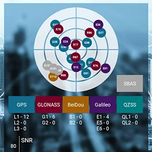
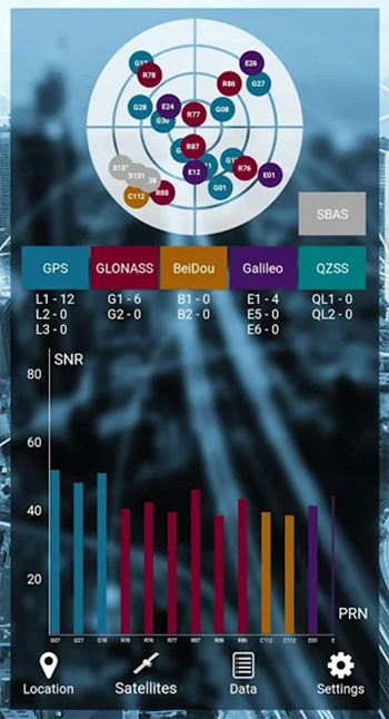
With the SXblue ToolBox iOS application, the user can analyze the position data provided by the SXblue receiver, as well as location metadata.
More important for SXblue clients, the application can record, save and transfer raw data from the GNSS receiver, thereby allowing post-processing activities. The application also acts as a NTRIP client, capable of connecting to a NTRIP server for real-time kinematic (RTK) corrections, and thus allows the receiver to issue very accurate location information.
Receiver configuration is easy through the application, with the ability to set up and save user-defined commands for subsequent use. The settings include constellation to be used, differential source, NTRIP login credentials list and more.
In addition, the iOS application includes a series of audible and visual alarms that are user-configurable to determine the thresholds of information provided by the SXblue GNSS receiver.
The main features of the iOS SXblue ToolBox application are:
Display of location information and quality of positioning data
Skyplot of all-in-view constellations: GPS, GLONASS, Galileo BeiDou, QZSS, SBAS
Recording of raw data and data transfer
NTRIP/DIP client to receive RTK corrections
Terminal to send commands and view the output data of the SXblue device
Audible and visual alarms
Activation of options and licenses via the application.
The GPS World staff reported live from Intergeo Sept. 17-19 in Stuttgart, Germany. The massive trade show, dubbed the “global hub of the geospatial community,” brings together more than 19,000 visitors from more than 114 countries and features approximately 640 exhibitors. Check out the latest industry news, as well as photos and videos from the event.
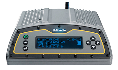
Trimble has added capabilities to its real-time network (RTN) portfolio, including the Trimble Pivot Platform and the Trimble Alloy GNSS reference receiver.
The new capabilities will enable operators to continue to meet the ongoing demand from surveyors, mapping professionals and precision farmers for accurate, reliable corrections derived from real-time networks.
The announcement was made at Intergeo 2019, the world’s largest conference on geodesy, geoinformatics and land management, taking place Sept. 17-19 in Stuttgart, Germany.
Boosting RTN performance. A well-established network software, the Pivot Platform manages and controls small, mid-size and countrywide GNSS networks. By applying sophisticated atmospheric models to reduce systematic errors, highly accurate GNSS corrections are generated and made available for a wide range of field applications.
BDS-3 now supported
Both Pivot and Alloy now access BeiDou Generation III (BDS-3) signals.
Trimble Pivot version 4.3 has been enhanced to track and store BDS-3 — RTN operators worldwide now have the ability to provide their customers with additional satellite signals to offer even more robust and reliable positioning for their applications. This update also includes a simplified Chinese user interface, providing easy-to-use software operations for Chinese RTN operators.
Released in 2018, the Alloy GNSS reference receiver was designed with the processing power needed to deliver high-quality data from multiple GNSS constellations. Alloy version 5.42 firmware tracks all available and planned GPS Block IIIA L1C and BDS-3 signals, empowering operators with a full GNSS constellation dataset.
“These updates keep the Trimble Pivot Platform and Alloy on a future driven path,” said Mark Richter, strategic marketing director, Real-Time Networks and Services portfolio for Trimble’s Advanced Positioning Division. “Our focus is to continue to deliver enhancements influenced by market demands and advancements in technology, which deliver next-generation RTN hardware and software to our customers.”
The Trimble Pivot Platform and Trimble Alloy GNSS reference receiver updates work in conjunction to provide quality GNSS corrections to network operators and end users.
Trimble real-time networks and services
Trimble RTN networks and services are a widely used GNSS infrastructure solution. Spanning a variety of applications and industries worldwide, Trimble’s hardware is specifically developed for RTN real-world environments while the software integrates seamlessly into the RTN solution for exceptional real-time performance.
The flexibility of Trimble’s solution enables users to collect, manage and analyze complex information faster and easier, improving productivity and efficiency.
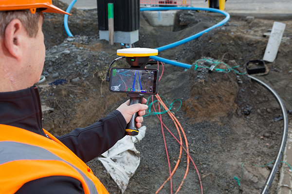
Trimble has introduced its Trimble SiteVision system, an outdoor augmented reality (AR) solution that enables users to visualize 2D and 3D data on virtually any project site with cellular or internet connectivity for easier and more efficient planning, collaboration and reporting.
Combining hardware and software in an integrated, lightweight handheld or pole-mounted solution, users can view 3D models and assets in a real-world environment at a 1:1 scale, from any angle or position.
The system consists of:
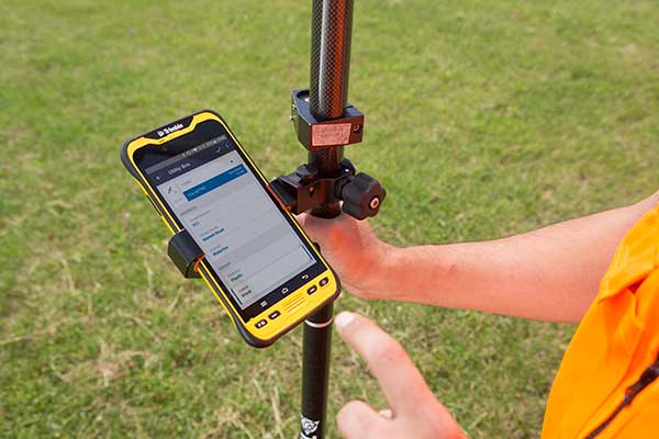
Hardware: The Trimble SiteVision integrated positioning system integrates the Trimble Catalyst DA1 antenna, electronic distance measurement (EDM) rangefinder and power management into a lightweight, handheld device that connects to a user-supplied Android mobile phone.
Software Subscription: Available to single users on a monthly or yearly basis. The SiteVision software subscription combines Trimble’s high-accuracy positioning services and cloud-based processing technology to create a centimeter-accurate AR system. The system leverages Trimble cloud-based processing to manage and deliver data and design models.
SiteVision enables users to visualize digital models from a wide range of data collection, design and constructible modeling tools in open industry-standard formats including IFC and LandXML.
For civil projects, SiteVision accurately visualizes data from Trimble’s Quantm, Business Center and Novapoint; design data from Civil 3D and Bentley OpenRoads; and GIS data from Esri ArcGIS software.
Photo: Trimble
SiteVision powers building information modeling (BIM) projects with open data from Trimble’s Constructible BIM solutions including SketchUp and Tekla, and BIM data from Autodesk Revit and AutoCAD software. For utility companies, PLS-CADD power line design, Distribution Design Studio (DDS) and other industry-specific design data is also supported.
Using Trimble Connect cloud-based hosting, SiteVision can access models from all stages of the lifecycle of infrastructure and buildings—from initial concepts of roads or buildings through the operations and maintenance phase of the assets—to increase collaboration, enhance work accuracy and ultimately improve operations and utilization.
SiteVision simplifies complex concepts by allowing users to blend digital content with real-world environments. For example, city planners can visualize a new building design in the exact spot it is to be erected, a work crew could identify the exact position of underground cables or pipes before digging, an electric utility can confirm placement of poles and lines with customers and crews, or a construction supervisor could assess the progress of heavy equipment by visualizing actual work performed against the site plan.
“It’s easier to understand complex ideas when we can see them in a real-world context,” said Mark Nichols, general manager at Trimble. “SiteVision improves our understanding of projects and worksites with a handheld device that is accessible to a wide range of users. Augmented reality is now ready for everyday use in a wide range of applications.”
Trimble SiteVision is available to order now through Trimble’s authorized distribution channels for Civil Engineering and Construction, Geospatial and Buildings.
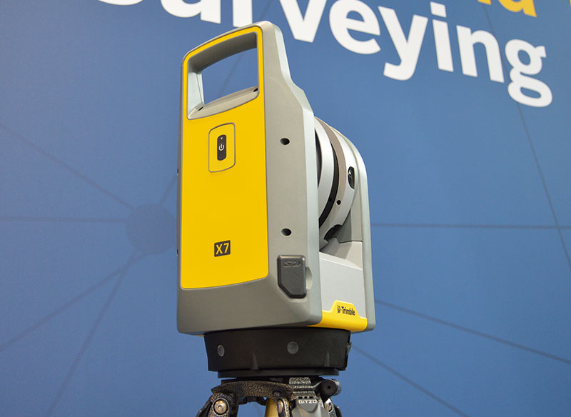
The Trimble X7 is designed for surveying, construction, industrial and forensic applications. (Photo: Allison Barwacz)
Trimble has released its X7 3D laser scanning system at Intergeo 2019, which took place Sept. 17-19 in Stuttgart, Germany. According to the company, the system is designed to enable professionals of all scanning levels to quickly and easily capture precise 3D scanning data to produce high-quality deliverables.
The X7 is designed for surveying, construction, industrial and forensic applications. The scanner features Trimble X-Drive technology, survey-grade self-leveling and a smart calibration system.
“We are really excited to bring the X7 to the market,” Gregory Lepere, marketing director, optical and imaging, Trimble, told GPS World. “It’s a very simple solution but offers a lot of smart technology. Every time you turn the instrument on, the automatic calibration will start, so you’re guaranteed to have all of the specifications all of the time.”
It also integrates streamlined workflows to provide automatic registration of point cloud data in the field with Trimble Registration Assist.
“The feature bringing the most simplicity to the solution is the Trimble Registration Assist technology, which is a full registration in the field, bringing all of the scans together thanks to self-leveling IMU technologies combined with cloud-based software,” Lepere said.
Survey applications
For surveyors and geospatial professionals, the X7 provides fast and balanced performance in both indoor and outdoor environments and is ideal for industrial survey/tank calibration, civil infrastructure, general surveys, road intersection surveys, utilities, mining, and historical documentation and renovation, Trimble said.
The X7 is fully integrated with the Trimble Perspective software, which enables scans and images to be captured, fully registered together, refined, controlled and exported to a variety of established data format for Trimble and non-Trimble software suites.
Building design and construction applications
For users in building design and construction, the X7 assists with measurement problems and improves field productivity for a broad range of applications in architecture, engineering and construction industry projects.
For these applications, the X7 is fully integrated with Trimble Field Link software to provide streamlined workflows specific to the building construction industry — from scanning to modeling to field layout.
Forensics applications
According to Trimble, the X7 can perform in demanding conditions and offers easy setup for investigators and law enforcement. It also pairs with the company’s Trimble Forensics Capture software.
The Trimble X7 is expected to be available in the first quarter of 2020.
The GPS World staff is reporting live from ION GNSS+ Sept. 16-20 in Miami, providing news, photos, videos and more. According to show organizers, this year’s conference brings together international leaders in GNSS and related positioning, navigation and timing fields to present new research, introduce new technologies, discuss current policy, demonstrate products and exchange ideas.
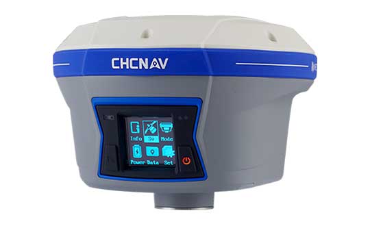
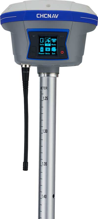
CHC Navigation has released and is immediately shipping its new i90 IMU-RTK GNSS Series receiver. The i90 IMU-RTK GNSS Series is designed to dramatically increase GNSS real-time kinematic (RTK) availability and reliability.
The i90 is powered by the company’s latest inertial measurement unit (IMU) and RTK technology to provide robust and accurate GNSS positioning in any circumstances.
Unlike standard micro-electro-mechanical (MEMS)-based GNSS receivers, the i90 GNSS IMU-RTK combines a high-end calibration and interference-free IMU sensor with a state-of-the-art GNSS RTK engine and advanced GNSS tracking capabilities.
The i90 is designed to increase productivity and reliability of survey projects. No complicated calibration process, rotation, leveling or accessories are necessary with the i90 GNSS Series. Just a few meters’ walk will initialize the i90 internal IMU sensor and enable RTK survey in difficult field environments. The i90 GNSS automatic pole-tilt compensation boosts survey and stakeout speed by up to 20%.
“Our new i90 IMU-RTK GNSS Series is pushing the boundaries of conventional GNSS survey by extending RTK positioning availability and reliability,” said George Zhao, CEO of CHC Navigation. “CHCNAV is the GNSS technology enabler, making high-end GNSS solutions available for every surveyor.”
TerraFlex users can now synchronize data directly to their on-premise Esri geographic information system without cloud services.
Photo: Trimble
The new software workflow — called offline data transfer — is possible through the integration of Trimble TerraFlex and the Trimble Positions Desktop add-in for Esri ArcGIS Desktop.
TerraFlex is a field solution that enables mobile workers to easily collect, manage and edit their geospatial feature data.
The new workflow provides an alternative to using Trimble cloud services for storing and transferring GIS feature data collected with the TerraFlex platform. In addition, TerraFlex field data collected via this workflow using a Trimble GNSS receiver can be post-processed directly inside the Trimble Positions Desktop add-in for improved positional accuracy.
“With this new feature, TerraFlex fulfills the need of organizations such as government agencies and utility providers who cannot keep their data in the cloud because of regulatory constraints or business rules,” said Rachel Blair-Winker, business area manager for Trimble Mapping & GIS solutions.
“By introducing the new workflow to our TerraFlex software platform, customers who prefer direct desktop methods of transferring data between field and office (such as USB) and need post-processing capabilities can now benefit using this new solution without having to change their current business practices,” Blair-Winker said.
Trimble TerraFlex is available online or through Trimble’s Authorized Geospatial distribution channel. The mobile apps are available in Apple’s App Store and the Google Play store.
The Trimble Positions Desktop add-in is available through the Trimble Geospatial distribution channel. The new workflow functionality will require the latest version of both applications.
With the calendar pages turning rapidly and as we get closer to the witching hour of geospatial voodoo, more items have surfaced to discuss and educate ourselves on in relation to “the change.”
Let’s delve into these topics and break each down into what the common surveying and geospatial practitioner will need to know with the advancements in coordinates, geodesy and our everyday uses.
NATRF2022: The continental U.S. replacement for NAD83 and NAVD88
It is no secret that with the advancing use of GNSS technology, flaws in both existing horizontal and vertical datums establishing our National Spatial Reference System (NSRS) have been identified and exposed.
NGS estimates that NAD83 is non-geocentric by over two meters, while the model establishing NAVD88 contains a tilt of approximately one meter across our continent.
For most geospatial practitioners, these flaws are minimal to the integrity of their data. It does, however, give us a glimpse of how assumptions of geodetic information can produce incorrect modeling of surveying and mapping data and could lead to more flawed earth models without significant changes to their structure.
With a great number of surveying and mapping practitioners using GNSS technology with little or no knowledge of the origins of our NSRS, it is a good time to provide the primers below to explain the history of our geodetic datums.
Besides my previous article, follow these links for much more thorough technical information:
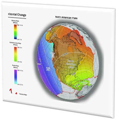
With changes in both horizontal and vertical datums, slight variations in the data we are used to seeing will seem insignificant, but will require the user to pay close attention to potential data traps when converting between the old and new systems. The NGS graphics below depict the severity of datum change in the horizontal and vertical component across the U.S.
Image: NGS
Depending on where you are working, new state plane coordinates will vary from –2 meters to +4.5 meters from previously published values, with elevations fluctuating up to one meter from previous norms. All these changes are due to the increased knowledge of our world using various forms of emerging technology not thought possible several decades ago.
These new measuring methods and studies, including GNSS and gravity monitoring, have allowed scientists and geodesy experts to establish more accurate geographic location systems than past terrestrial ways and procedures.
We have geodetic monuments and marks everywhere; will they still be usable?
The short answer to this question is an unequivocal yes, but with some caveats. Use of GNSS monitoring has proven we reside on tectonic plates that move slowly over time; thus, the geographic values (latitude and longitude) used to calculate any number of coordinate value systems are changing as well.
Image: NGS
Relational data between established points are not likely to change, but studies have shown significant shifts in areas that result in movement of our previously considered “unmovable” monuments.
With additional parameters and characteristics being introduced with the 2022 datum, time and tectonic plate shift are main factors in establishment of a point.
The concept of a “permanent” point no longer exists in relation to a published and unchangeable coordinate value of horizontal and vertical data. The surveying and geospatial data collector must recognize that the user is establishing a particular X/Y/Z or N/E/Z value for that exact moment in time and it, theoretically, will change from the moment one steps away from the point.
This may be too “splitting of hairs” for most users, but the new system simply recognizes the reality of the moving data-collection stage, no matter how minute.
This datum re-establishment has been a monumental undertaking (no pun intended), and NGS deserves many kudos for coming up with a realistic solution for a complex problem.
However, most of its users still have a problem, and it lies within the standard unit of measurement: the U.S. survey foot. NGS (and its predecessor, U.S. Coastal and Geodetic Survey) have always used the meter for the basis of all units of measurement (as does the rest of the world.) The new 2022 datum is bringing us, the surveyors and mappers, to a new reality — nationwide adoption of the international foot. Let the grumbling and arguments begin!
The meter vs. international foot vs. US survey foot
The unit of measurement aptly named the “foot” has existed since early times, with most sources crediting King Henry I of England making a decree that his foot shall become the standard for measurement.
No matter where the definition of the foot came from, it has varied slightly throughout history. The origin of the meter (or metre, as it’s known worldwide) also has a variety of beginnings. The most established story starts from John Wilkins, an English philosopher, who published in 1668 what he described as a new standard of measurement based upon the length of a pendulum that swings approximately 38 inches across in one second. This length was eventually named the meter by an Italian scientist.
Another century later, King Louis XVI of France issued a integration law establishing the modern metric system with weights and measures having a base-ten system of units and sub-units. Within this system was the meter with a new length definition of being one ten millionth (1/10,000,000) of the distance from the North Pole to the Equator.
Upon completion of the calculations, a rectangular bar made of platinum and iridium was created to establish the “standard” meter from which all future measurements would be based.
The United States first recognized in 1866 the metric system and the meter (set forth as one meter equaling 39.37 inches). During this time, the International Commission of the Meter officially adopted the physical meter bar as the standard.
Over the next 100+ years, many studies were undertaken to re-establish the length of the meter. Using wavelengths of various elements, including cadmium, mercury, neon, zinc, helium, thallium and krypton, new definitions were created. In 1983, the current definition of the length of the meter was finalized.
The meter is now based upon the speed of light in a vacuum (299,792,458 m/s) with the meter being the length traveled in 1/299,793,458 of a second. While the length is very close to the original measurements set forth over the centuries, it is better defined for reproduction worldwide without having to possess a standard bar or other device.
To further muddy the standardization of units, in 1959 an international agreement was made by Australia, Canada, New Zealand, South Africa and the United Kingdom so one yard would equal 0.9144 meters. Meanwhile, the U.S. National Bureau of Standards published a notice that all survey-related measurements will remain based so one one yard equals 3600/3937 meters or 0.91441083 meters.
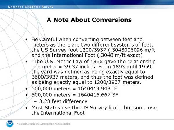
Image: NGS
We have two different measurements for the foot. What’s the big deal?
The difference between the two standards is two parts in one million; while that doesn’t affect everyday physical measurement, it does cause havoc on coordinate systems with values beyond the millions. (See NGS video “Two Right Feet?” for details).
What makes it even more confusing is that states across our country vary on which “foot” is standard within their legislation and daily practice. Currently (at the date of publication), six states recognize the International Foot as their standard unit of measurement, with four states not defining it. The remaining states have officially adopted the U.S. survey foot as their standard unit of measurement.
NGS has suggested that starting with the 2022 datum change, the U.S. survey foot will not be supported in applications and software produced by them for geodetic computations. It will be limited to meters and the international foot, so they are recommending that states update their existing definitions to change to the international foot along with recognizing the 2022 datum as the official coordinate-system base.
How to train our profession, the construction industry and John Q. Public on the new datum
I would be lying to you if I said I’m not concerned with the rollout of the new datum and with converting all surveying and mapping work to the international foot. My biggest concern is not with those direct relationships I have with my staff and fellow professionals within my company.
My main concern starts with these two areas: the tens of thousands of surveying practitioners working within projects containing state-plane coordinate systems in addition to contractors and other mapmaking providers using survey-grade equipment for construction and other mapping applications.
Both groups have little to no technical knowledge of the intricacies of state-plane coordinate systems and the geodesy network “behind the curtain.” To paraphrase a well-known mortgage company with an app-based home loan system, “push button, get data” is the limit of most users’ knowledge when it comes to state-plane coordinates.
Add to this the double-edged sword of real-time networks, where the user does not have to be concerned with setting up a base station, and the potential problems could get worse.
While there will be a few early and timely embracers of the new datum, the majority will dig their heels in and refuse to switch. When the conversion to the 2022 datum is upon us, many users will drag their feet on learning about the new system as existing projects continue under the old datums.
Until there is a mandate by government agencies and others, many newer projects beginning around the adopting time will remain on NAD83 and NAVD88 until directed otherwise.
Most practitioners I have spoken with on this issue agree that it will be a tricky period for surveying and mapping. Rather than get bogged down with negativity and fight change, the surveying, mapping and geospatial community should do the following:
Rally our professions around these significant changes to educate our technicians and future professionals.
Coach contractors and other trades who rely on the technology to understand the new system.
Work with governmental agencies at all levels to educate them about what these changes entail and why to make the appropriate revisions to codes and statutes now.
Capitalize on this opportunity to teach the public about who we are and how spatial data is part of everyone’s life.
All these points are paramount to the success of the datum upgrade and need to be followed through to the end. Ultimately, the faster we adopt and adapt, the better our geospatial world will be. There is lots of work ahead of us, but as the staff at NGS has shown us, the hard work necessary to make significant change is well worth the effort.
CALLING ALL SURVEYORS AND GEOSPATIAL PROVIDERS!
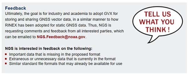
NGS announces GVX data format for GNSS vector processing
The National Geodetic Survey (NGS) is requesting input and feedback on a new data format for sharing real-time kinematic (RTK) GNSS vector information.
The new format will be like the static GNSS standard, Receiver Independent Exchange (RINEX), and is utilized by most software packages and the Online Positioning User System (OPUS).
The new GNSS Vector Exchange format (GVX), will introduce a new industry standard for sharing of RTK vectors across differing platforms and software packages.
Earlier users of GPS-based data collection remember the number of proprietary files created by each manufacturer, and having their own unique format for data and attribute interpretation. In response, the NGS created RINEX to help standardize data collection as a universal file format that would easily be adopted by receiver and software producers.
That same goal is being set with the introduction of the GVX format as the next step in data-collection standardization for GNSS RTK vectors. GVX elements include (but are not limited to) the following:
A-priori coordinates for the end points of each vector
Receiver and antenna types
RTK and real-time network (RTN) settings, if applicable
Quality control metadata (e.g., PDOP, number of satellites used, orbit type, etc.)
The introduction to the new format along with technical specifications and examples are on the NGS website.
The National Society of Professional Surveyors (NSPS) works directly with NGS to provide input on maintaining and updating the National Spatial Reference System and will include significant assistance with educating geospatial data providers with the upcoming 2022 datum change and implementation of the North American Terrestrial Reference Frame of 2022 (NATRF2022).
The surveying, mapping and geospatial professions have exciting times ahead with these cool upgrades from NGS, so we need to take advantage of the calm before the storm to educate ourselves to make the most of the opportunity.
Geospatial data surrounds all of us, and we are the profession specifically educated for correctly and efficiently keeping a handle on it all. It all starts with growing your knowledge a little bit each day. Please join me in growing the profession as well.
CHC Navigation has launched a new website to convey its expanding role as a provider of geospatial and GNSS products and solutions.
“Our new website provides a clear insight of who we are and where our ambition lies when developing, delivering and supporting high-end, professional and innovative GNSS-based solutions to our customers,” the company stated in a press release. “The website offers extensive refreshed and updated resources presenting the entire scope of CHCNAV solutions to make any surveying work more effective.”
In commenting on the new website, George Zhao, CEO of CHC Navigation said, “We have been enjoying double-digit growth for over 16 years demonstrating the strength of CHC Navigation in the professional GNSS-based markets. Our new website brings a comprehensive vision of our technology and innovation, expanding compelling solutions and our global customer care approach.”
Founded in 2003 and based in Shanghai, China, CHC Navigation creates GNSS navigation and positioning solutions.
A new case study focuses on improving the endurance and navigational precision of underwater autonomous systems.
Sonardyne, designer and manufacturer of underwater positioning and inertial navigation, describes the challenges to increase navigation capability for subsea monitoring and inspections. Sonardyne joined the National Oceanography Centre (NOC) and L3Harris ASV on a two-year project to develop new positioning technologies to extend the limits of AUVs and UUVs.
The project — Precise Positioning for Persistent AUVs (P3AUV) — is supported with £1.4 million in funding through Innovate UK’s research and development competition for robotics and artificial intelligence in extreme and challenging environments.
Sending autonomous and unmanned underwater vehicles (AUV, also known as UUVs) out on missions that will last for days or weeks, unaided by vessels or other supporting offshore infrastructure, is a major goal for the ocean science, offshore energy and defense sectors.
Photo: Sonardyne
Sustained Ocean Observation. The research community aims for sustained ocean observation without the need for ship support, especially in ice-covered polar areas. Long-duration navigational capability is also a key enabler for persistent covert surveillance operations in the defence sector. And emerging applications include resident seabed-based systems, deep-sea mining, aquaculture and UXO surveys for renewable installations.
Autonomous AUVs would remove the need for a surface vessel, reduce risk to personnel, and reduce costs. Users could survey more seabed for longer and with fewer or even no people offshore.
The team is developing ways to provide greater positioning accuracy for long-endurance operations in deep water, while also reducing power requirements. The team will also be increasing the use of autonomy to make long baseline (LBL) positioning transponder box-in faster and easier, with onboard data processing and calibration.
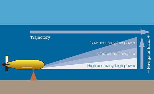
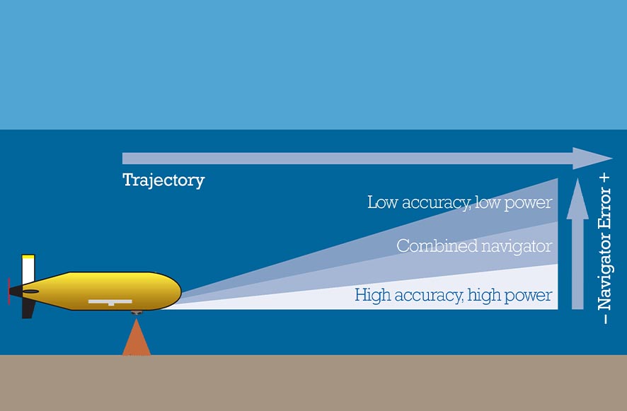
High-power INS input. Central to this work is the AUV’s acoustic and inertial navigation system (INS). Low-power sensors have much lower navigation accuracy and often have to surface to correct positioning error with a GPS fix. The team seeks to integrate low- and high-power sensors to achieve high performance at much lower power consumption.
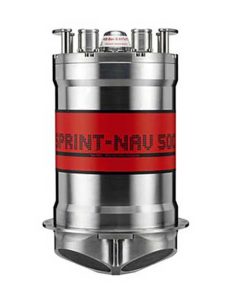
For instance, the NOC’s Autosub Long Range (ALR) uses a low-power microelectronic mechanical system (MEMS) supported by separate Doppler velocity log (DVL) and ADCP input to calculate how far it has traveled on missions, which can be several months long. To increase the ALR’s positioning accuracy over longer distances, the team is using the Sonardyne SPRINT-Nav all-in-one subsea navigation instrument alongside MEMS technology to work towards high-precision solutions that save space and power.
Image: Sonardyne
Accuracy during ascent and descent. The project also involves improving positioning accuracy when subsea vehicles transition through the water column. This is a notoriously difficult area for AUV deployments, because it relies on the Doppler velocity log (DVL) being able to lock on to the seafloor (bottom lock), so that vehicle XYZ velocities can be calculated, supported by pressure data.
However, DVLs are range limited, so there is often a period where the DVL is out of range. When there are thousands of meters of water between the surface and the seabed, this can introduce significant positioning uncertainty.
By using the acoustic Doppler current profiler (ADCP) capability in Sonardyne’s SPRINT-Nav INS instrument (looking down) and a second Syrinx DVL (looking up), the team could then build up a layer-by-layer profile of the water column velocities to be used as tracking layers.
The objective is to reduce positioning errors significantly during both the dive and surfacing phases of an operation. Results depend on the variability of the current in any given area.
The data collected during the descent and surfacing phases can be processed to provide a full ocean-depth current profile — collection of which is required for many offshore energy projects and can be valuable for ocean research.
MicroSurvey Software, part of Hexagon, has released its new field data-collection software platform for Android users.
FieldGenius for Android, version 1.0, is first release of the company’s new multi-platform field software built on the Android platform. It supports most popular GNSS sensors on the market today.
FieldGenius is third-party, brand-neutral data-collection software used by many surveyors. The new release builds on decades of innovation MicroSurvey has invested into the original FieldGenius software, providing users with an easy-to-use and intuitive mobile data-collection software package for the next generation.
New features include dynamic data panels synchronized with the map views. A fresh user interface provides familiarity for existing FieldGenius users while offering new tools, simplified workflows and readily available data that surveyors require at the point of work to make informed decisions in the field.
“Surveyors, dealers, and distributors from every corner of the world have been demanding an Android based version of MicroSurvey FieldGenius for years,” said Marc Veinotte, global sales and OEM manager at MicroSurvey. “This is the first release of our new multi-platform field data collection software that will provide a consistent user experience across a wide cross section of data collection devices. MicroSurvey continues its hardware neutrality strategy offering support for almost every brand of popular and upcoming GNSS receiver on the market today.”
Early adopters of FieldGenius for Android will receive additional benefits and participate in the newly created MicroSurvey Technology Innovation Group (MTIG).