Category: Survey

  • Trimble Launches R2 GNSS Receiver at Intergeo

    Photo: TrimbleTrimble debuted its new R2 GNSS receiver at Intergeo 2015, held this week in Stuttgart, Germany.

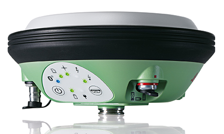
    The R2 GNSS receiver is a receiver that works with Trimble handheld devices and iOS, Android or Window mobile handhelds, smartphones and tablets using Bluetooth or USB connectivity. When paired with a mobile device, the receiver adds professional-grade GNSS capabilities for better accuracy. The rugged Trimble R2 provides GIS and survey professionals the flexibility to choose the mobile device, workflows and accuracy they need based on applications.

    Trimble R2 GNSS Receiver for Mobile Devices

    The Trimble R2 GNSS receiver is compact and portable, weighing 2.4 pounds. With one-button operation and a field swappable battery, the receiver can be pole or vehicle mounted or carried on a backpack. The R2 is a multi-constellation receiver that supports GPS, GLONASS, Galileo, BeiDou and QZSS satellite signals, as well as SBAS.

    With a variety of standard and optional correction capabilities, the Trimble R2 can achieve sub-meter to centimeter positioning for a broad range of accuracy requirements. The receiver is an option for the Bring Your Own Device (BYOD) strategy.

    “Today’s geospatial professionals require flexible solutions which allow for configuration to meet their specific job requirements,” said Ron Bisio, general manager of Trimble’s Surveying and Geospatial Division. “The Trimble R2’s versatility to support GIS and survey workflows as well as BYOD deployment enables geospatial professionals to collect data using the mobile device, workflow and accuracy they choose.”

    Workflows – GIS and Survey Field Software

    Designed for both GIS field data collection and survey workflows, the Trimble R2 receiver integrates with Trimble TerraFlex mapping and GIS field software and Trimble Access survey field software.

    TerraFlex software is a scalable cloud-based solution for geospatial data collection. By pairing the R2 with a smart device or Trimble handheld running TerraFlex, the solution addresses a wide variety of field requirements, including attribute-rich GIS data collection on consumer and professional devices.

    Trimble Access software supports the workflows of everyday surveying tasks such as topographic and control surveys and specialized surveying tasks such as roads, monitoring, tunnels and mines. By pairing the receiver with a Trimble handheld running Trimble Access or TerraFlex field software, the Trimble R2 is a versatile solution that supports the full range of geospatial data collection workflows for both GIS and survey applications.

    Flexible Accuracy

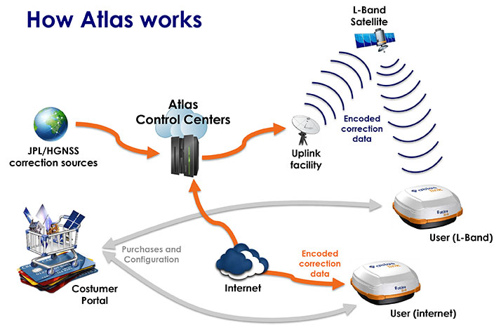
    The receiver is capable of receiving a broad range of corrections from traditional RTK, VRS networks and SBAS to Trimble RTX correction services via cellular/IP connections or satellite (L-band), the Trimble R2 provides high-accuracy data worldwide.

    The R2 GNSS receiver can leverage the entire portfolio of subscription-based Trimble RTX correction services to accommodate a wide range of applications and accuracy requirements. This includes CenterPoint RTX (less than 4 centimeters), RangePoint RTX (less than 50 centimeters), and ViewPoint RTX (less than 1 meter) correction services.

  • INTERGEO 2015: senseFly eXom Drone Capable of Millimeter Accuracy

    senseFly has published a white paper named “Generating highly accurate 3D data using a senseFly eXom drone” which presents the results of two photogrammetric land surveys of a construction site. The project was completed earlier in September using two senseFly eXom close mapping and inspection drones, and the announcement was made during INTERGEO, held Sept. 15–17 in Stuttgart, Germany.

    Figure 8 - Check point results for flight 1, taken from Postflight Terra 3D's Quality ReportThe results demonstrate that 3D point clouds produced with an eXom quadcopter can reach a global precision comparable to that of a total station survey and meet the typical accuracy requirements of construction projects, according to a news release from senseFly.

    The first eXom survey (figure 8) achieved 2.1 millimeter accuracy in X, 1.9 millimeter in Y and 0.1 millimeter in Z (RMSE). The second eXom survey (figure 9) achieved 0.8 millimeter (X), 0.5 millimeter (Y) and 4.2 millimeter (Z).

    “This degree of absolute accuracy from a drone is unparalleled and positions the eXom as a surveying instrument that is comparable in performance to standard total stations,” said Andrea Halter, senseFly’s co-founder. “These results were due, in part, to the high 38 MP resolution and sharpness of the flight’s images, captured by the main camera inside eXom’s TripleView head. Add to this image quality the ability to operate close to the terrain and the introduction of highly precise ground controls and you have a recipe for exceptionally accurate 3D data.”

    Figure 9 - check point results for flight 2, taken from Postflight Terra 3D's Quality ReportTwo eXom drones flew separate survey missions at an altitude of 14 meters above the site, achieving an average ground sampling distance (GSD) of 2.2 millimeters, senseFly says. All the flights were completed using the drone’s Interactive ScreenFly flight mode, whereby the UAV (unmanned aerial vehicle) is controlled using a handheld ScreenFly controller connected to senseFly’s eMotion X flight planning and control software.

    This flight mode’s “cruise control” feature, combined with its auto-trigger function, enabled each of the eXom drones to survey the 1,100-square-meter site in a single flight. Meanwhile, the live on-screen feedback from the drone’s five different navcams and ultrasonic proximity sensors helped the operator ensure that no contact was made with either the on-site crane or any the trees surrounding the complex site, senseFly says.

    “This project’s flights took place at 14 meters above the ground, but with the eXom’s Distance Lock feature we are able to safely fly just 4 meters away, so it isn’t unrealistic to think that the accuracy we achieved could be improved still further.”

    To download the eXom accuracy white paper click here.

  • Septentrio Launches AsteRx-U and AsteRx-U Marine

    AsteRxU_left_orientation-W

    Septentrio this week is launching two successors to its APS-U: The AsteRx-U and the AsteRx-U Marine multi-constellation dual-antenna receivers. The AsteRx-U will be presented to the public for the first time at two trade shows this week. ION GNSS+ takes place Sept.14-18 in Tampa, Fla., and INTERGEO 2015 will be held in Stuttgart, Germany, Sept. 14-18.

    The AsteRx-U and the AsteRx-U Marine incorporate the latest GNSS tracking and positioning algorithms and interference mitigation. Machine-control users in the agricultural and construction industries, as well as users in marine and mining industries, benefit from a complete system with integrated UHF radio, Wi-Fi, USB, Bluetooth and cellular connectivity and a spectrum analyzer, Septentrio said. All configurations can be done via the on-board web interface.

    The AsteRx-U and AsteRx-U Marine feature a full range of positioning techniques and algorithms to ensure that users have the highest accuracy and reliability. The spectrum analyzer enables users to visualize the RF spectrum. Based on its extensive experience with real-life interference sources and their mitigation, Septentrio has developed interference mitigation technology that automatically counteracts various kinds of ambient intentional and unintentional RF interference.

    The AsteRx-U family of receivers is built around Septentrio’s latest ASIC, GReCo4, which was introduced in 2014. It incorporates built-in jamming detection and countermeasures, multi-path rejection, fast acquisition and other advanced features. Both receivers have more than 500 hardware channels to track all available constellations (GPS, GLONASS, Galileo, Beidou, IRNSS and QZSS) and feature many algorithms: LOCK+ technology to maintain tracking during heavy vibration machine use and IONO+ technology to assure the accuracy of the position even in regions of elevated ionospheric activity.

    The AsteRx-U has decimeter- and centimeter-level RTK positioning including TerraStar. The AsteRx-U Marine also supports Veripos PPP augmentation services. It includes extra anti-jamming technology to counter Iridium and INMARSAT-uplink interference, as well as an extra antenna connector for a dedicated L-band antenna to optimize L-band reception at high latitudes.

    Straightforward to set up and integrate with existing systems, the AsteRx-U and AsteRx-U Marine use any device with a web browser to facilitate usability and configuration for the user.

    “We want to make it easy for our customers to use high-accuracy positioning in their work,” said Jan Leyssens, Septentrio product manager. “Using the integrated communication functionality in the compact and portable AsteRx-U, users won’t have to worry about adding their own modems or UHF radios to get access to corrections.”

    Leyssens continued, “The receiver web interface is available wirelessly on any mobile device. It was designed together with several of our key customers, resulting in an interface that is not only easy to use by field operators, but also provides many useful troubleshooting tools, such as the spectrum analyzer, to solve problems in the field and minimize downtime.”

    Septentrio will be at Booth 318 at ION GNSS+, and at Hall: 4, Booth: D4.014, at INTERGEO.

  • Hemisphere GNSS’ Atlas Makes Trade Show Debut at INTERGEO

    Hemisphere GNSS’ Atlas Makes Trade Show Debut at INTERGEO

    Hemisphere GNSS will be showcasing its new Atlas GNSS global correction service at the INTERGEO 2015 Conference and Trade Fair Fair in Stuttgart, Germany, held Sept. 15-17. Hemisphere GNSS will exhibit at Booth E6.093.

    The Atlas correction service offers innovative and accessible correction service options, providing performance in demanding applications and environments, Hemisphere said. Available through various subscription and bundle options, Atlas is a flexible correction service with correction data delivered via L-band satellites or over the Internet at accuracy levels ranging from meter-level to sub decimeter-level.

    ATLAS-Launch-1-howworks-W

    The Atlas platform offers endless possibilities through hardware, software, and branding integration into various products and customized solutions, the company said. Several new Hemisphere products with Atlas support targeted for specific applications will be on display at INTERGEO, including Hemisphere’s latest AtlasLink GNSS smart antenna. Other Atlas capable products, including R330, V320 and VS330 will also be showcased.

    Photo: AtlasLinkAtlasLink, the multi-GNSS, multi-frequency smart antenna, is preconfigured to receive corrections from the new Atlas platform. The bundled AtlasLink solution provides users worldwide with the easiest way to utilize Atlas corrections — either directly from AtlasLink, or on their existing receivers via innovative new technologies built into AtlasLink.

    “AtlasLink is a game changer” declared Chuck Joseph, Hemisphere GNSS CEO and president. “On its own it is a fantastic smart antenna with industry-leading RTK, connectivity and management capabilities. Further, when you add in the ability to deliver Atlas GNSS corrections to equipment you already own, from any vendor, you have a real powerhouse that will allow you to get much more from your existing GNSS equipment.”

    Live demonstrations of Atlas GNSS global correction service and AtlasLink GNSS smart antenna will be given daily. Contact Hemisphere GNSS to schedule a time or visit booth E6.093 during the show.

  • Survey Market Key to Maxtena’s Growth

    Vanja Maric
    Vanja Maric

    Exhibiting at CTIA Super Mobility 2015, Vanja Maric, director of sales and marketing for Rockville, Maryland-based antenna-maker Maxtena, pointed out the challenge that exists for antenna makers in an uncertain drone market: forecasting what will happen next and planning for that future.

    “The problem with the drone space its so volatile and so fragmented, and it’s very, very hard to predict,” Maric said. “Speaking to industry leaders in the UAV market, they don’t even know what it’s going to be in three years, and it’s very hard to put all your cards in that.”

    That fragmentation is largely a dichotomy between the needs of the professional-grade market and the recreational drone pilots, Maric said. Maxtena is currently the antenna provider for several large UAV manufacturers, although confidentiality prevents them from being named.

    Maxtena M1516 L1 GPS GLONASS Passive Embedded Antenna
    Maxtena M1516 L1 GPS GLONASS Passive Embedded Antenna

    “It all comes down to the necessity of precision, and different industries have different needs. UAVs, for example, some use very simple GPS patch antennas, simple receivers and precise location is not as important,” he said. “Then you have guys in the professional space where it is a necessity.”

    That necessity right now is in the survey market, particularly RTK solutions for construction and mining operations in emerging countries. The company has seen an uptick in customers from Asia looking for antennas for Beidou. More specifically, Maric said handhelds for lone worker tracking in open pit mining in China has had “fantastic” growth. The M1227 antenna released earlier this year accomplishes this goal.

    Maxtena GPS antennas at CTIA 2015
    Maxtena GPS antennas at CTIA 2015

    “It’s not just hardware; they have a lot of costs—software, mapping— in on all that, and if that package is right, you have something special. However, don’t forget: The antenna is the link between you and the satellite. That antenna has to be right; that’s what most companies forget,” Maric said. “You can have the best receivers and software in the world, but if you can’t make the link you can’t do it.”

  • Aerial Photography, Surveying Top FAA-Approved Business Uses for UAS

    Aerial Photography, Surveying Top FAA-Approved Business Uses for UAS

    A Sensefly eXom UAV inspects a structure.
    A Sensefly eXom UAV inspects a structure.

    The Association for Unmanned Vehicle Systems International (AUVSI) today released a report that finds more than 25 types of business operations have been approved by the Federal Aviation Administration (FAA) to fly unmanned aircraft systems commercially in the National Airspace System (NAS). According to the report, aerial photography received the most exemptions followed by real estate and aerial surveying. The report also finds that exemptions have been approved in 49 states.

    “These figures show that businesses across every industry sector have been waiting to use UAS for years and are excited to finally get this technology off the ground,” said Brian Wynne, president and CEO of AUVSI. “From inspecting bridges and power lines to filming movies and supporting emergency services, the applications of UAS are virtually limitless and enable researchers, public agencies and businesses to do things that were previously considered to be impossible.”

    In May 2014, the FAA announced it would consider granting exemptions for certain low-risk commercial UAS applications under Section 333 of the FAA Modernization and Reform Act of 2012. Since then, the agency has received more than 2,700 requests and approved more than 1,400 petitions.

    Chart: The Association for Unmanned Vehicle Systems International (AUVSI)AUVSI analyzed the first 1,000 exemptions approved by the FAA. Specifically, the report finds:

    • The approved exemptions cover more than 25 types of business operations, with aerial photography receiving the most approvals with 512. Real estate followed with 350 exemptions and general aerial surveying with 301 exemptions.
    • Exemptions were approved for operators from 49 states. California received the most with 114, followed by Florida with 97 and Texas with 82.
    • California companies also manufactured the most platforms mentioned in the approvals, totaling 140. Florida followed with 19. In all, 22 states house manufacturers of platforms approved in the first 1,000 exemptions.
    • More than 90 percent of the first 1,000 exemptions were granted to small businesses.
    • Companies that received exemptions generate at least $500 billion to the U.S. economy annually and represent more than 600,000 jobs.

    While the Section 333 process has continued to unlock the potential of UAS technology, AUVSI emphasized that regulating by exemption is no substitute for finalized rules.

    “For the full potential of the UAS commercial market to be realized in the U.S., the FAA needs to finalize its small UAS rule as quickly as possible,” Wynne said. “Once this happens, we will have an established framework for UAS operations allowing anyone who follows the rule to fly. The positive effects of the regulation will be felt across the whole country.”

    An economic impact study released by AUVSI in 2013 found the UAS industry will create more than 100,000 new jobs and more than $82 billion in economic impact within the first ten years following UAS integration.

    The complete study, including state-by-state data, is available.

  • Tallysman Introduces VeraPhase 6000 High-Precision GNSS Antenna

    Tallysman Introduces VeraPhase 6000 High-Precision GNSS Antenna

    Tallysman's VeraPhase 6000 high-precision GNSS antenna.
    Tallysman’s VeraPhase 6000 high-precision GNSS antenna.

    Tallysman, a manufacturer of high-performance GNSS antennas, announces the commercial availability of the VeraPhase 6000 antenna series, a family of antennas that provides the lowest axial ratios (horizon to horizon, through all azimuths) across all GNSS frequencies (70 percent), a tight PCV (± 1mm through all frequencies, azimuths, and elevations), and a consistent PCO through all frequencies.

    The performance of the VeraPhase rivals that of choke ring antennas, but is much lighter, smaller and more economical, Tallysman said. The antenna family is designed for use in survey, precision RTK and reference antenna applications.

    The VeraPhase 6000 also provides an available PCB within the base of the antenna for integration of a custom system board such as a dual-band or RTK GNSS receivers or other applications.

    The VP6000 family provides high receive RHCP gain over the full GNSS spectrum:

    • low GNSS band (1164 MHz to 1300 MHz)
    • L-band correction services (1525 MHz to 1559 MHz)
    • high GNSS band (1559 MHz to 1610 MHz).

    Each model features a robust, high IP3, pre-filtered LNA to minimize desensing from high-level out-of-band signals, including 700 MHz LTE, and that yet still provides a noise figure of less than 2.5 dB. Non-pre-filtered versions are also available with a noise figure of less than 1.5 dB.

    The VP6000 antenna family is available in three formats:

    • A survey-grade all-band antenna that provides 35-dB LNA gain and is available with a robust rubber bumper for field use.
    • An all-band base station antenna is available with 35-dB LNA gain or with an internal 15-dB pre-filtered pre-amp for OEM applications.
    • An all-band reference antenna that features a 50-dB gain LNA, a conical radome to shed snow ice and birds, and is available with a robust monument mount for sub-millimeter precision.

    Each antenna has a well defined phase centre offset relative to the antenna reference plane.

    The base housing of the VP6000 is IP67-compliant and weighs less than 700 grams. The antenna is 167 millimeters wide at the top, 110 millimeters wide at the base and 110 millimeters in height. Each model has a 5/8-inch x 11 TPI thread for mounting and is available with either a TNC or an N-type connector.

    A white paper is available on Tallysman’s website.

    Tallysman’s booth at INTERGEO is in Hall E8, Booth 038. Follow GPS World on Twitter for the latest news from INTERGEO.

  • Federal Register Notice Seeks Comments on GPS L1 Band Interference Test Plan

    Federal Register Notice Seeks Comments on GPS L1 Band Interference Test Plan

    UPDATE (9/10/15): A public workshop will be held in Washington, D.C., on Oct. 2 to provide an opportunity to discuss the draft test plan and address questions before the close of the public comment period.  The workshop will be held in the RTCA NBAA/Colson Room, 1150 18th St. NW, Suite 910, Washington, D.C., 20036. Click here to register for the workshop.


    The U.S. Department of Transportation today published a Federal Register Notice seeking public comment on a draft test plan for the GPS Adjacent Band Compatibility Assessment effort. The plan aims to obtain interference tolerance masks for GNSS receivers in the L1 radiofrequency band (1559-1610 MHz).

    The objective of the test is to collect data to determine Interference Tolerance Masks (ITM) for categories of GPS and GNSS receivers processing signals in the 1559-1610 MHz Radionavigation Satellite Service (RNSS) frequency band, as well as receivers that process Mobile Satellite Service (MSS) signals to receive differential corrections.

    Demand for commercial spectrum to support broadband wireless communications — in particular, LightSquared — has led the government to consider repurposing various radio frequencies, including the satellite communications bands next to GPS. The ITMs will be used to assess the adjacent band interference power levels that can be tolerated by GNSS receivers processing desired signals in the RNSS band.

    The document outlines the requirements, the overall test plan, and the associated output data needed to successfully perform this component of the GPS Adjacent Band Compatibility assessment.

    The plan can be downloaded here. Deadline for comments is Oct. 9.

    In December 2012, the DOT developed its GPS Adjacent Band Compatibility Assessment Plan that identifies the processes to:

    • Derive adjacent-band transmitter power limit criteria for assumed new applications necessary to ensure continued operation of GPS services, and
    • determine similar levels for future GPS receivers utilizing modernized GPS and interoperable GNSS signals.

    The DOT has previously held three public workshops to discuss the Adjacent Band Compatibility Assessment.

  • UNB GAPS for Precise Point Positioning Gets Update

    The next version of the UNB GPS Analysis and Positioning Software (GAPS), version 5.9.1, is now available.

    The new version of the precise point positioning software includes several updates and new features, including creation of GAPS Basic and Advanced user submission pages.

    The GAPS Basic user submission page allows for quick and easy submission of observation files for users who frequently use GAPS’ default processing options.

    The GAPS Advanced user submission page includes:
    •    User-selection of the orbit and clock products to be used.
    •    User-selection of the carrier-phase and pseudorange observables to be used.
    •    Optional use of GPS L2C in place of P2 for all satellites currently transmitting L2C.
    •    Optional use of GPS L5 in place of L2 for all satellites currently transmitting L5.
    •    Optional use of static-mode satellite clock interpolation (if 30s clock product is used and logging interval < 30s).
    •    User-selection of GDOP cut-off threshold.
    •    User-selection of positional convergence condition and maximum number of iterations for least-squares filter.
    •    Enhanced the cycle-slip detection algorithm (following Blewitt, 1990).
    •    A minimum of 4 satellites per epoch are required before estimation begins.
    •    User-selection of all available neutral atmosphere delay (NAD) prediction model and mapping function (MF) combinations.

    NAD prediction models include: UNB-VMF1 (NCEP), UNB-VMF1 (CMC), VMF1 (ECMWF), UNB3m, GPT2 (1×1 deg.), ESA 2.5 and None

    Mapping function options are: Vienna MF and Niell MF.

    •    User option to not estimate NAD.
    •    User option to not estimate tropospheric gradients.
    •    Optional use of a user-provided receiver antenna calibration file.
    •    NAD estimation automatically terminated if receiver rises above neutral atmosphere threshold (50,000 ft = 15,240 m).
    •    Added option to estimate precipitable water (if a meteorological file is submitted).
    •    New .ion, .cmp, .nad, and .DOP output files as well as modified formatting of the .par file.
    •    Improved reporting of processing parameter options and results in the HTML output.
    •    Added receiver clock and DOP plots.
    •    Added height component to kml output.

    For information on the processing strategy, visit the web page. Your feedback (suggestions, bug reports, etc.) is welcome via the GAPS Development Team email: [email protected].


  • SBG, Viametris Present 3D Indoor Scanning System at INTERGEO

    SBG, Viametris Present 3D Indoor Scanning System at INTERGEO

    The iMS 3D indoor mapping system by Viametris uses an Ellipse-A by SBG for roll and pitch data.
    The iMS 3D indoor mapping system by Viametris uses an Ellipse-A by SBG for roll and pitch data.

    SBG Systems will join Viametris in presenting a new 3D indoor scanning system at the INTERGEO trade show, which will be held Sept. 15-17 in Stuttgart, Germany.

    The iMS 3D is a mobile 3D indoor scanner generating continuous point clouds. For this brand-new model of indoor mobile mapping system, or iMMS, Viametris chose SBG Systems’ miniature Attitude and Heading Reference Sensor (AHRS), the Ellipse-A. The iMS 3D is easier to transport, install and set up than previous iMMS. The iMS 3D also integrates new sensors, including the Ellipse-A from SBG Systems.

    Based on the SLAM technology, the iMS 3D is equipped with three lidar profilers, each taking 40,000 points per second. The main lidar provides the horizontal profile, which also contributes to the continuous calculation of the iMS 3D position in the building. Two lateral lidars give vertical profiles, including the ceiling. While the user walks, pushing the iMS 3D at normal speed, the 3D profile of the room appears on the screen, since the system records 3D measurements of the same room. Easy to manipulate, one person is enough to survey every corner of the building with the iMS 3D.

    During the survey, the 360-degree camera takes a spherical picture every two meters for a full documentation of the building. This solution makes indoor survey 10 times quicker than traditional methods usually using distance meters, Viametris said, adding that the iMS 3D delivers a combination of point density, acquisition speed and accuracy suitable for the building trade industry.

    At the office, the user accesses a centimeter-level accuracy 3D survey as a point cloud and pictures by using the Viametris processing and browsing software. The user can import the point cloud in CAD software (Autodesk Revit, AutoCAD, MicroStation, Rhino, etc.) to easily produce 2D maps or 3D models. The point cloud can be colorized with the colors of the pictures taken during the survey, which greatly improves the environment understanding. Additionally, the user has access to contextual 360-degree pictures, making objects such as radiators, extinguishers or lights simple to distinguish and locate.

    Ellipse-A.
    Ellipse-A.

    Already integrated in other Viametris ultraportable technologies, the Ellipse-A has been chosen for this new generation of indoor mobile mapping system, or iMMS. “We integrated an Ellipse-A in our 2D system and were very happy with the results. It was obvious to us that the Ellipse-A will be part of our new iMMS,” said Jérôme Ninot, president of Viametris. The Ellipse-A is used to correct the horizontal profile. While the user is pushing the iMS 3D through the rooms, unevenness, slopes and ramps, cables or door thresholds can cause noise in the point cloud. The Ellipse-A keeps the point cloud clean by correcting the horizontal lidar data frames used to build the trajectory.

    The Ellipse-A AHRS provides roll and pitch data accurate to 0.2° at 200 Hz. “The Ellipse sensors are much more efficient than the previous IG-500 product line,” said Mr. Ninot.

    Keeping lidar and camera data precisely synchronized can be difficult because the camera focal time is susceptible to vary. In mobile scanning, even a slight latency might cause an offset. For example, the picture will not be located on the right place inside the point cloud. Viametris decided to connect the camera and the three lidars to the Ellipse-A to ensure a highly accurate and repeatable synchronization.

    At INTERGEO 2015, the iMS 3D will be presented at stand # B4.049 and the ELLIPSE-A will be presented at stand # G4.079.


  • Leica GS14 GNSS Features Hybrid Communication Technology

    Leica GS14 GNSS Features Hybrid Communication Technology

    Leica Viva GS14
    Leica Viva GS14

    Leica Geosystems, manufacturer of the Leica Viva GNSS Unlimited series and GS14 GNSS receiver, has added a new hybrid communication technology to its compact and powerful GNSS smart antenna. The latest generation Leica Viva GS14 GNSS now supports Verizon CDMA solutions along with all standard 2G/3G networks and UHF TX/RX radio in a single device, making it a professional GNSS receiver with all three communication systems built in. Users simply slide in their SIM card to experience instant connectivity for faster and easier field communications and SmartNet RTK corrections, the company said.

    The Leica Viva GS14 3.75G&UHF supports 2G GPRS, 3G HSPa+, CDMA (EV DO) and UHF TX/RX radio between 450 and 470 MHz in one compact housing. Professionals can choose whether they want to use the UHF radio to transmit or receive work, a 2G/3G cellular network, or Verizon CDMA. No external equipment is required.

    “The Leica Viva GS14 with its hybrid communication technology is the most advanced compact GNSS receiver in the market,” said Bernhard Richter, Leica Geosystems GNSS business director. “The addition of CDMA modem capability in a unique all-in-one design offers unmatched flexibility in communication choices.”

    The Leica Viva GS14 3.75G&UHF is available today throughout the United States. Ordering information and details are available from all authorized U.S. Leica Geosystems representatives and dealers.

  • Calgary Company Switches from GPS Handhelds to TerraGo

    Calgary Company Switches from GPS Handhelds to TerraGo

    The Trans-Alaska Pipeline System in Interior, Alaska
    The Trans-Alaska Pipeline System in Interior, Alaska.

    Enmapp, a pipeline services company based in Calgary, Alberta, Canada, has replaced its proprietary GPS handhelds with TerraGo Edge and Eos Arrow receivers. TerraGo Edge is a mobile GPS data collection platform that integrates with the Eos Arrow series of GNSS receivers to bring advanced sub-meter and centimeter real-time accuracy to any smartphone or tablet.

    Enmapp provides data collection services to energy companies for pipeline construction and maintenance. Before TerraGo Edge, Enmapp relied on all-in-one GPS handheld devices, but became convinced the cost, features and performance were increasingly out of line with the mobile revolution fueled by Apple and Android solutions. After an extensive evaluation, Enmapp selected TerraGo Edge and Eos Arrow 100 receiver for a field trial so they could compare their performance against the GPS handhelds.

    Eos Positioning's Arrow 200 Bluetooth receiver now supports Hemisphere's Atlas correction service,
    Eos Positioning’s Arrow 200 Bluetooth receiver now supports Hemisphere’s Atlas correction service,

    After downloading the app on the crew’s iPads and pairing the Eos Arrow 100 via Bluetooth, they were up and running within minutes. “The results were astounding,” reads a TerraGo press release. “Not only did the Eos GPS receiver meet the GPS handheld’s accuracy requirements, in some cases it was much better. The efficiency of the crews was far superior with the native iPad features of TerraGo Edge, versus the old-style stylus and PDA screens of the legacy equipment. The labor costs were also reduced because they were able to use real-time GPS from the Eos Arrow 100 and reduce post-processing. Enmapp declared TerraGo Edge and Eos the clear winner, and have now deployed TerraGo Edge on all field personnel iPads, along with a Bluetooth-connected, sub-meter GPS receiver, the Eos Arrow 100.”

    “The hardware savings are enormous with the new GPS kit at less than $10,000 compared to the old kit which was over $70,000. But the ongoing reduction of project labor costs is even more valuable over time,” said Lance Fugate, program manager at Enmapp. “The cost reductions and efficiency improvements are a game-changer for us. As our industry continues to look for innovation from its service providers, TerraGo Edge enables us to deliver more efficiently. We can pass these savings directly to our customers with each and every future project.”

    The TerraGo Edge is available for either iOS or Android.

    Below is an exclusive interview with John Timar about TerraGo Edge from the GEOINT 2015 conference.

    Jean-Yves Lauture of Eos Positioning discusses the Arrow 200 GNSS receiver at the Esri User Conference.