Trimble, together with its distribution partner Ultimate Positioning Group (UPG), announced the availability of Trimble VRS Now correction service in Queensland, New South Wales, South Australia, Tasmania and Victoria.
Trimble is also now offering the Trimble VRS Now correction service in Oregon’s Willamette Valley.
The commercial subscription service provides surveyors, civil engineers, geospatial professionals and other industry specialists in these areas with instant access to real-time kinematic (RTK) GNSS corrections without the need for a base station.
Using both GPS and GLONASS constellations, the Trimble service delivers centimeter-level RTK corrections customized for each GNSS receiver’s location anywhere in the network via cellular communications. The Trimble VRS Now service supplies accurate, reliable and easy-to-use GNSS positioning for a variety of applications including surveying, urban planning, urban and rural construction, environmental monitoring, resource and territory management, disaster prevention and relief and scientific research, Trimble said.
“The addition of VRS Now to Trimble’s current portfolio of corrections technologies and services in Australia highlights our ability to meet any accuracy, delivery, availability and financial consideration across a variety of applications and markets,” said John Sprivulis, business area director of Trimble’s Positioning Services Division in the Asia Pacific. “Trimble is effectively creating a national positioning infrastructure to meet Australia’s future needs.”
Trimble VRS Now in Australia is a continuation of Trimble’s focus on providing solutions that enable customers to increase productivity by simplifying access to high-precision accuracy around the world. Similar VRS Now services are operating in parts of the U.S. and Europe.
In addition, the Australian VRS Now service supports the Trimble Pivot Field Mobile App, which provides up-to-the-minute information on the VRS Now system status for users in the region.
Because OmniSTAR CORS service in the area is being phased out, existing Australian users will be automatically transitioned to the Trimble VRS Now service, which provides easy access to high accuracy and reliable positioning within the network coverage area.
Service in Australia and Oregon is a continuation of Trimble’s focus on providing solutions that enable customers to increase productivity by simplifying access to high-precision positioning around the world. Similar VRS Now services are operating in Illinois, Indiana, Iowa, Nebraska, Colorado, Florida, Alabama, Mississippi, Texas, and parts of Europe.
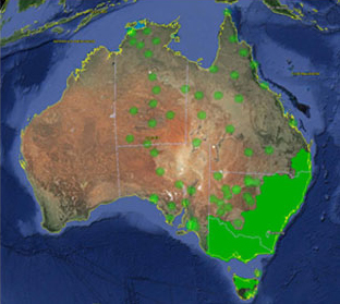
Trimble VRS Now coverage in Australia. Photo: Trimble
Trimble, together with its distribution partner Ultimate Positioning Group, announced the availability of Trimble VRS Now correction service in Queensland, New South Wales, South Australia, Tasmania and Victoria.
Trimble is also now offering the Trimble VRS Now correction service in Oregon’s Willamette Valley.
The commercial subscription service provides surveyors, civil engineers, geospatial professionals and other industry specialists in these areas with instant access to real-time kinematic (RTK) GNSS corrections without the need for a base station.
Using both GPS and GLONASS constellations, the Trimble service delivers centimeter-level RTK corrections customized for each GNSS receiver’s location anywhere in the network via cellular communications. The Trimble VRS Now service supplies accurate, reliable and easy-to-use GNSS positioning for a variety of applications including surveying, urban planning, urban and rural construction, environmental monitoring, resource and territory management, disaster prevention and relief and scientific research, Trimble said.
“The addition of VRS Now to Trimble’s current portfolio of corrections technologies and services in Australia highlights our ability to meet any accuracy, delivery, availability and financial consideration across a variety of applications and markets,” said John Sprivulis, business area director of Trimble’s Positioning Services Division in the Asia Pacific. “Trimble is effectively creating a national positioning infrastructure to meet Australia’s future needs.”
Trimble VRS Now in Australia is a continuation of Trimble’s focus on providing solutions that enable customers to increase productivity by simplifying access to high-precision accuracy around the world. Similar VRS Now services are operating in parts of the U.S. and Europe.
In addition, the Australian VRS Now service supports the Trimble Pivot Field Mobile App, which provides up-to-the-minute information on the VRS Now system status for users in the region.
Because OmniSTAR CORS service in the area is being phased out, existing Australian users will be automatically transitioned to the Trimble VRS Now service, which provides easy access to high accuracy and reliable positioning within the network coverage area.
Service in Australia and Oregon is a continuation of Trimble’s focus on providing solutions that enable customers to increase productivity by simplifying access to high-precision positioning around the world. Similar VRS Now services are operating in Illinois, Indiana, Iowa, Nebraska, Colorado, Florida, Alabama, Mississippi, Texas, and parts of Europe.
An Australian company is proposing putting GPS tracking devices in footballs as early as 2015, according to a report by News Corp Australia. Both the National Rugby League (NRL) and the Australian Football League (AFL) are considering using the trackers in footballs as early as next year. The AFL and several National Football League (NFL) teams in the United States already use trackers for player monitoring.
The battery-operated devices, the size of a 10-cent coin, are made by Melbourne-based company Catapult. The devices have the capacity to influence score decisions and analytics, Catapult said. They can track the ball’s speed and time held in possession by a player, and help provide deeper analysis of the game. Spectators also would get a glimpse, with more details of the game made available to them.
Catapult already manufactures and sells GPS devices worn by players in various sports including the AFL, and also makes indoor stadium tracking systems for athletes and elite sports teams. The NRL is aware of the technology, but has not yet decided to implement it.
For the current football season, this year the NFL began using RFID chips for in-game player tracking at 17 stadiums, just over half. The RFID chips, manufactured by MotionWorks, allow the NFL to measure player orientation and capture location information, which is then shared with fans. The data is also used by broadcasters to show plays.
A quarter of NFL teams and 10 major U.S. college programs are using GPS trackers, mostly for training and injury prevention.
“The number one goal of this system right now is trying to help prevent injury as well as help us with the rehab process. There are a lot of different things that goes in to it, but the biggest thing is ‘how can we monitor guys on the field to help us get the information’?” said Eric Ciano, strength and conditioning coordinator of the Buffalo Bills.
“I think us being able to manage practice and how we do it with the GPS system, how we train with that thing year-round, [has] allowed us to take a lot of the guesswork out of how tired your team is, where your pulls, your tears are,” said Jimbo Fisher, head coach of Florida State University football. “Our soft tissue injuries are down 88 percent in the last two years because we’ve been able to apply that. And we use it full-time to gain that information. It’s on my desk, the first thing when we walk in every day.”
User equipment incorrectly interpreting data from a satellite set “unhealthy” led to an apparent constellation outage for roughly 1,000 fleet vehicles across Australia in April. The problem was traced to the way a GPS/telecomm chip reacted to an extended navigation test aboard SVN-49, having to do with the recently launched IIF satellite, SVN-64.
Although SVN-49 was set unhealthy at the time, the integrator-equipped fleet vehicles across the continent experienced periods of several hours without satellite visibility, in unobscured environments.
The U.S. Air Force GPS Operations Center reported that in mid-May tests, “PRN 30 [was] broadcasting almanac datasets that do not reflect constellation changes that occurred since it was last uploaded with navigation message data. [. . . ] The utilization of these almanacs in a manner that regards the time of week, but neglects or mishandles the week number (effectively executing as if the current week number is the week number associated with these almanac parameters), will result in an increasing error in visibility determination and other almanac based estimations (elevation/azimuth, Doppler shift, SV clock offset from GPS time, etc) as the dataset’s actual week offset from the current week increases.”
The situation occurred once previously, in 2011 with Mercedes in Europe. The problem was traced to chips from the same manufacturer, installed by the car-maker’s integrator partner, also misinterpreting data from a satellite set unhealthy while broadcasting system test data.
A few months ago I wrote in the magazine’s Out in Front column about the surprising abundance of BeiDou-centric papers to be presented at the upcoming ION GNSS+ conference, to which I very much look forward — both the abundance and the conference as a whole. With GLONASS encountering stormy weather of late, and Galileo plugging steadily along but not quite making up time, it seems increasingly possibly that the first GNSS of choice may constitute GPS+BeiDou, if certain spectrum questions can be worked out. News of an advance in Australia further heralds this likelihood.
Researchers at Curtin University in Perth, Western Australia, have put forth a method integrating GPS and BeiDou signals, in an effort particularly aimed at urban canyons. In Australia at least, the visibility of BeiDou’s five geostationary and five inclined geosynchronous orbit satellites hovering above the Asia-Pacific region can bring added punch to any receiver experiencing skyviews obscured by skyscrapers. The same problem occurs in open-pit mines, said Curtin University professor Peter Teunissen. Open-pit mines are a very big thing in Australia.
For those surprised to find this flying Dutchman, the inventor of the LAMBDA method for GNSS carrier phase ambiguity resolution, popping up in Australia, it appears he has a secondary appointment at Curtin University. He remains based, as he has for 20 years, at the Delft University of Technology in the Netherlands, where he is head of the Department of Earth Observation and Space Systems.
I wish I had a secondary appointment somewhere.
“By combining GPS with Beidou,” announced Teunissen and colleagues at the Cooperative Research Centre for Spatial Information, “we are making use of Beidou’s 14 new satellites that cross our sky at a high angle, increasing satellite availability, improving positioning capability and ultimately creating a system that is perfect for both urban and mining environments.”
Beidou of course has a ways to go to achieve its fullness at 35, perhaps as soon as 2020. Combining all and sundry GNSS, more than 100 GNSS satellites are expected to be operational by 2016, so algorithms making use of multiple signals and systems have moved to the fore. As we well know.
“The emergence of new GNSSs, together with the linking of different systems, has enormous potential for improving the accuracy, integrity and efficiency of positioning worldwide, enabling much more reliable data,” Teunissen added.
Precise positioning services could boost Australia’s gross domestic product by $13.7 billion by 2020, according to a recent report by a consultant for the Department of Industry, Innovation, Climate Change, Science, Research and Tertiary Education. (Maybe that’s where I should seek my secondary appointment; they’ve got a lot on their plate.)
In January of this year, Teunissen’s Curtin University group and Dr Dennis Odijk, from the Western Australian School of Mines (WASM), also announced a methodology integrating GPS with Galileo signals. Both projects were funded by the Australian Space Research Program.
Police in Mildura, Australia, have been warning people not to rely on Apple Maps after several people trying to find the town of 30,000 people became hopelessly lost in the bush in scorching temperatures, reported the Guardian. One man was stranded for 24 hours last week in temperatures of up to 115º Fahrenheit. Three more were rescued after following the directions given on Apple’s Maps applications. Apple Maps put Mildura in Murray-Sunset National Park, the second largest park in Australia and 70 kilometers from the town’s actual location.
The red pin shows the location Apple Maps directs drivers to. The purple pin is the location of the town.
“Police are extremely concerned as there is no water supply within the Park and temperatures can reach as high as 46 degrees (Celsius, 115º Fahrenheit), making this a potentially life threatening issue,” read a police statement. “Some of the motorists located by police have been stranded for up to 24 hours without food or water and have walked long distances through dangerous terrain to get phone reception.”
Today, the Guarian reports that Apple wasn’t completely wrong in directing Australians who searched for “Mildura” to the midst of the Murray-Sunset National Park. The Australian government’s official gazetteer includes a location called “Mildura Rural City” at the place where Mildura was previously marked on iPhone maps.
As reported by The Register, the official gazetteer contains an entry at the precise place to which Apple was directing drivers until making a correction on Monday. The gazetteer contains 36 entries for “Mildura,” including the one for Mildura Rural City, which has “official” status and is listed as a “district” (comprising an “agricultural area, county, district, local government area, parish or region”). Mildura Rural City is an area of 22,000 square kilometers in the northwestern part of Victoria state, but Geoscience Australia located it at a specific point, in this case the middle of the park rather than the town.
Apple’s mistake was to ignore another entry for Mildura, which the gazetteer records as having the class of “POPL” (population center).
Locata Corporation announced today that its integration partner, Leica Geosystems Mining, has begun to sell — and ship to their global mining customers — a Locata-powered positioning systems that it calls “the world’s first.”
The Leica Jps (the Jigsaw Positioning System powered by Locata) integrates GNSS and Locata’s ground-based GPS-like networks. The result is a seamless and a completely new “GPS everywhere” experience for Leica’s customers, the company said. This new capability is now in use at Newmont’s Boddington Gold Mine, northwest of Boddington, Western Australia. The mine has published an independent article describing the LocataNet and Jps systems deployed for the mine’s drill rig fleet. It reported that drill rig up-time and efficiency have skyrocketed to unprecedented levels since the Jps system was commissioned.
Locata-enabled nonstop positioning brings benefits to machine automation in mining because Locata fills in the many gaps in GPS signal availability experienced in an open-cut mine, Leica said. The Leica Jps ensures a reliable and transparent experience for users with demanding machine guidance applications because it uses all available signals, satellite-based or Locata, without interruption.
“The Locata-based Jps is therefore the world’s first system which can justly be considered as ‘a backup for GPS’,” reads a Leica Geosystems statement. “Real-world operational performance, which is being reported by Jps customers, can only be described as ‘spectacular’.”
“Since deploying the Locata-powered Jps at Newmont Boddington Gold, there has been an increase in operational machine guidance availability of almost 23 percent – from 75 percent up to 98 percent,” said Brendon Lilly, product manager, Leica Geosystems Mining. “Newmont Boddington Gold is so happy with the results that they have turned off their GPS-only solutions altogether, and now rely solely (and successfully) on Jps alone. They have already installed Jps on 11 drills and intend to equip their entire high-precision fleet.”
“The ROI we offer our clients through the Jigsaw Positioning System is extraordinary. Market trends indicate CAPEX is in decline, so the parameters mines use to justify expenditure have become far more demanding,” said Stefana Vella, global marketing manager, Leica Geosystems Mining. “The unprecedented production levels and machine control uptime that result directly from using the Locata-powered Jps very quickly justifies the purchase of the system. Furthermore, it aids the justification of expenditure on the high-precision machine guidance systems themselves, for, when operated with the Jps, the ROI increases exponentially. Even in today’s market, it isn’t a difficult decision to make.”
Many mines around the world use machine guidance systems for drills, shovels, excavators, dozers, graders and more to execute the site plan work in real-time. This tight automation dramatically improves efficiency and productivity. At the core of these machine guidance systems are GPS-style receivers that provide vital positioning information, using the satellite signals to calculate a 3D position.
Unfortunately, in most open-pit environments satellite signals become obstructed, which slows or temporarily halts production. As pits become deeper the problems become worse, drastically reducing the number of satellites the receiver can “see” to achieve GPS-style positioning. In the past, mines and other machine automation users had no choice other than to resort to much less efficient alternatives, such as manual surveying. Reduced satellite visibility therefore negated the considerable investment and operational efficiencies gained from modern machine guidance systems. The key to virtually eliminate these issues is Locata’s new “GPS-backup or replacement” capability, Leica Geosystems said.
Locata’s Locatalite device is a ground-based transmitter that generates a GPS-like signal. LocataLites deployed around the pit rim can ensure almost 100 percent positioning coverage. Locata signals “fill-in” the GPS holes with a signal that is processed by the Jps in exactly the same way that GPS signals are. Locata is the only technology in the world that can do this. By backing up their GPS-based systems, mines have an always-on positioning network that works if satellite signals are unavailable in the pit due to physical or man-made obstructions. Jps LocataLites can be permanently positioned on site or moved at will, ensuring a mine’s Jps Locata network can be set up where and when needed.
“We all rely on electricity from public sources, but in areas where outages occur companies invest in backup generators,” said Nunzio Gambale, CEO and co-founder of Locata. “It’s exactly the same scenario for mining companies, where they are dependent on GPS. Locata gives you a GPS backup ‘generator’ – a world-first capability which is clearly a game-changer for the whole industry. Before Locata became available mines simply had to suffer through a slow-down when GPS-based systems became flaky. Leica Geosystems had the vision early on to recognize the enormous benefits provided by our technology advancements. They threw their corporate weight behind intensive product development, carefully integrating Locata technology into their world-first Jigsaw mining solutions. It’s a marriage made in heaven, and Jps customers will be the ones who really reap the rewards of Leica’s outstanding first-mover effort. There won’t be any ‘GPS doesn’t work here’ excuses in the future.”
John Carr, senior technical specialist at Newmont Boddington Gold Mine, puts it this way: “Look, it’s really this simple. If Locata had not invented the technology to help fix the GPS issues in a deep pit scenario I may as well have gone back home, started breeding pit ponies and sharpened up the picks and shovels… Open Cut Mines, just like everyone else that depends heavily on satellite navigation, are already hitting the wall at the outer limits of GPS technology. With Locata, we’ve virtually eliminated everyday GNSS signal challenges. And now we also have our own backup in place in case of a more significant or longer-term failure.”
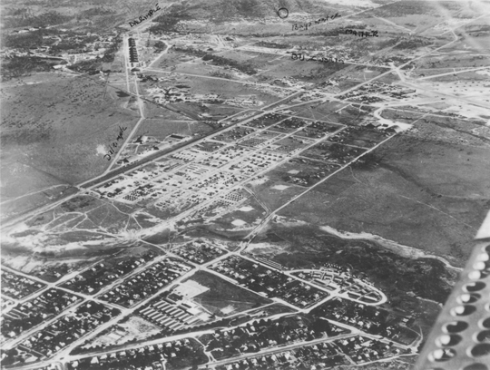
A U.S. Army camp near Townsville’s suburban areas, circa 1944.
By Tracy Cozzens
Beneath the surface of a tropical paradise in the city of Townsville on Australia’s Sunshine Coast lies a hidden maze of tunnels and underground bunkers, once said to be used by General Douglas MacArthur. Learning the secrets of this labyrinth that was a major World War II staging point for battles in the Southwest Pacific is the passion of Kevin Parkes of Geo Positioning Services, Townsville.
Parkes’ main tool is historic aerial photography, coupled with hours of research in the National Australian Archives and the National Library of Australia. To that he adds geophysical surveys of the infrastructure. Parkes is undertaking the geophysical surveying and mapping using an Ashtech ProMark 100 GNSS receiver and a Willy Bayot PPM Mk 3 magnetometer. He used the magnetometer and GPS receiver in parallel, later processing both data sets.
After the attack on Pearl Harbor and the Japanese advance through Asia, Townsville’s population bloomed from 30,000 to 120,000 by mid-1943. The rapid military influx stretched resources to the breaking point.
The U.S. Army 5th Air Force established the largest aircraft repair and maintenance facility ever built in the southern hemisphere at Townsville, and the site became the technical hub of U.S. military aviation. Air Force Service Command Depot #2 at Townsville was capable of overhauling 300 aircraft engines per month and performed aircraft assemblies, modifications, overhauls, and maintenance. Major resources and facilities serviced the Royal Australian Air Force, Australian and U.S. Armies, Royal Netherlands Air Force, Royal Air Force, Canadian forces, Royal Navy, and other allied forces.
“A visitor to Townsville today would be forgiven in asking where the artifacts of this massive military facility are today,” Parkes said. “There is very little remaining in any built structures that give any idea of what happened in this city 70 years ago.”
Parkes realized that underground cave shelters were most likely used for warehousing and storage, to keep stores out of the weather and protected from enemy action.
He describes one area he investigated, a park in Townsville used as an officer’s accommodation camp. Preliminary magnetic anomaly surveys indicated linear anomalies were beneath the park surface. A high-resolution survey gave samples of about 1.5-meter resolution.
“The difficulty was reducing all noise levels down to a minimum, including the X/Y positioning, so the GPS requirements came down to survey quality,” Parkes said. “It is absolutely critical that the GNSS receiver and magnetometer keep in synchronization during data collecting runs including under the frequently encountered tree canopies.”
To improve accuracy, Parkes avoids using real-time kinematic survey equipment. “That would involve having another electronic device operating and emitting more noise in the signal spectrum,” he said. The need to position the GPS antenna in close proximity to the magnetometer sensor was a major issue with all on-pole RTK systems.
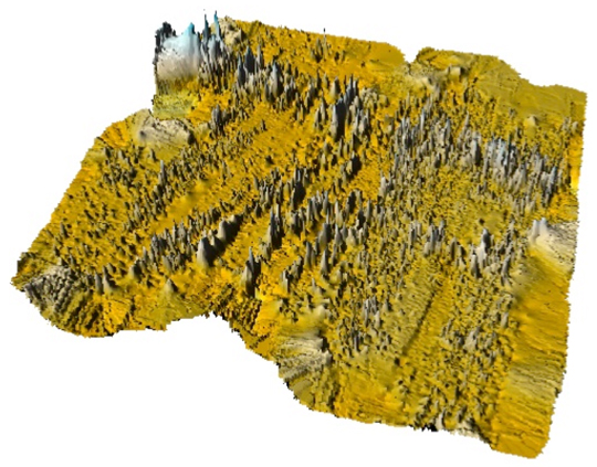
A U.S. Army air raid shelter under the officer’s accommodation camp, mapped with GPS and magnetometer data and using Surfer 3D surface mapping software.
With an Ashtech Promark 3, post-processed results were better than 100-millimeter X/Y coordinates. “The unit is lightweight and self-contained,” Parkes said. “The noise from the Ashtech survey-grade external antenna’s effect on the magnetometer data was insignificant.”
Still, this park had a grove of trees that defied every attempt to maintain GPS reception and consequently synchronize the magnetometer. Along came the Ashtech ProMark 100, a lightweight and self-contained receiver with external geodetic antenna with GPS and GLONASS. “My first attempt at surveying under the trees was spectacular to say the least,” Parkes said. “Synchronization with the magnetometer data was near perfect.”
The dual-constellation reception of the ProMark 100 became essential to the success of Parkes’ work. After more than a hundred data-collection passes with the magnetometer and ProMark 100 through the groves of trees, at no time did the Position Dilution of Precision (PDOP) rise to more than three, and at all times more than eight satellites were available. The ProMark 100 data is post-processed to improve accuracy. Parkes noted that ironically many of the most interesting finds have been collected under heavy tree canopy. Without the quality of the geographic positions enabled by the ProMark100 under tree canopy, Parkes said that much of his work would have been impossible to achieve.
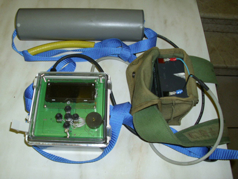
Parkes’ surveying equipment includes a magnetometer and a ProMark 100 GNSS receiver.
In fact, when Parkes first began his mapping project in 2005, he used a single-constellation GPS system and post processed the results against the local International GNSS Service (IGS) reference station. The GPS-only system worked very well until a grove of trees would interfere with the sky. Now with the ProMark 100 GNSS receiver, Parkes surveys using GPS L1 and GLONASS in continuous kinematic mode at a one-second collection rate. He then post processes the data against another ProMark 100 used as a local reference station.
To date, Parkes has mapped an underground railway, artillery observation posts, several shelters, fuel terminals and other yet-to-be-identified pieces of the vast infrastructure.
During his Research, Parkes mapped a major magnetic anomaly in Cleveland Bay. In 1770 Captain James Cook in the HMS Endeavour mapped the east Australian coast. Venturing into Cleveland bay, Cook noticed his compass behaving erratically, and named one island Magnetic Island. Today, a 3D surface model reveals a large magnetic anomaly heading across Cleveland Bay and straight towards Magnetic Island, 7 kilometers from Townsville. Experts who have examined the data believe that it is a naturally occurring magnetic anomaly about 800 meters wide. “It would appear that Captain James Cook was indeed a very capable navigator and cartographer,” Parkes said.
There is so much going on around the world in GNSS applications and developments that when we try to report what’s going on in a particular location, all we can really do is provide a snapshot. Each snapshot is simply a momentary picture captured at a single location — there really could be an entirely different picture around the next bend. However difficult this might be, it’s surely interesting to get a glimpse of things going on elsewhere, and hopefully we can capture some trends and innovations in the process…
In a continent the size of Australia, a country which is connected by so many lines of communication and commerce to so many other GNSS nations, it’s an impossible task to describe everything that’s going on, so I’m going to zoom in on an outfit I’ve known for a number of years and ask them to give me their “GNSS snapshot”.
GPSat in Macleod, Victoria (that’s at the bottom right hand corner of the continent), has been at the GPS game since 1993 and has crossed a number of applications boundaries. From initial OEM product and GNSS simulator representation through integration projects such as RTK container positioning at ports in East Swanson and Port Botany, huge open-pit excavator systems, and all the way to race horse velocity/position tracking systems — GPSat has grown in experience and capability over almost two decades of innovation.
GPSat got so deeply into integration programs that the company now offers not only products and systems, but also GNSS engineering services or as they put it ‘Engineering Turnkey Project’ development. A deal of those projects were connected to the now defunct Australia AirServices Ground-based Regional Augmentation System (GRAS) – Australia’s answer to SBAS and to some extent to GBAS.
While the rest of the world was focusing on satellite-based and ground-based augmentation systems, Australia was stirring up interest in an alternate system that took advantage of a large number of existing ground radio systems used by AirServices for air-traffic communications along the major air-traffic routes. Other countries have similar radio infrastructures and also became interested in the GRAS concept as an alternative to the more expensive satellite GEO broadcast of data. The GRAS system was to use the same principles as SBAS/WAAS, but correction and ionospheric data was to be relayed through the existing network of ground radio stations, uplinking this data using GBAS/LAAS messages to aircraft also equipped and certified for GBAS/LAAS approach and landing. The system design eventually drew support and recognition from the International Civil Aviation Organization (ICAO) and was ready to be prototyped/fielded in Australia, when AirServices unexpectedly pulled the plug.
We won’t dwell here on the reasons that this project ended, rather on the by-products which grew out of years of GPSat’s support to AirServices GRAS program, including large amounts of data collection and processing using WAAS ground reference receivers at test installations at Darwin, Melbourne and in the US.
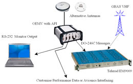
GPSat developed ground emulations of GRAS ground systems that could also be used for airborne testing. In advance of GRAS ground station fielding, the GVT Emulator provided engineering reference station capability for testing and data collection. The GMMReceiver provides a monitoring and validation tool using the actual VHF data-link and is still suitable for GBAS/LAAS system testing.
GMMReceiver.
GPSat also built a system which bridged PC-based commercial flight simulation applications such as Xplane or FlightSIM to drive a GNSS simulator, so that dynamic, simulated GPS signals are available to “fly” candidate airborne receivers. For anyone in GPS test engineering who has laboriously prepared static simulation scenarios, this could be a real time saver!
So, with the demise of GRAS, where will Australia go for precise enroute and approach navigation? With multiple GNSS constellations coming on line, the required integrity for air traffic management might just be satisfied by multiple constellations when used together. With approximately 30 GPS SVs (all original aviation integrity assessments were based on a Qty 24SV constellation), plus Galileo with GLONASS as a fall back, there might just be enough SVs for internal integrity assessment without external aids. This seems to be worth some investigation.
Now where would GPSat go next with all their technology and capability? “3D spatially aware machines,” you say. Well, I would never have guessed! So if you take GNSS positioning as the core, add inertial to overcome satellite outages, and use gaming software (an extension of the earlier flight simulator applications), add 3D models of the local area including other machine locations, and bring in radio communications between all the machines in the system — well, you have 3D spatially aware machines. Adding yet another twist — connect them all to the Internet via radio links and you can monitor and potentially manipulate these guys from anywhere in the world!
3D-SAM: Spatially aware machine.
This application is initially targeted at open-pit mining, where multiple vehicles and stationary ore/coal moving belts and other machines are constantly at risk of damage from collisions. The system is in use at AngloCoal for stockpile machinery primary navigation and Backup Anti Collision System (BACS).
Meanwhile, AirServices is working actively on GBAS/LAAS for aircraft approach and landing. Quantas has been landing Boeing 737 aircraft and the new giant Airbus-380 using this system at Sydney International Airport since 2006. Update/replacement of the Honeywell SLS-3000 GBAS/LAAS ground system by the US FAA approved SmartPath system is expected shortly.
Automatic Dependent Surveillance Broadcast (ADS-B) is also already operational in Australia too. ADS-B is an air traffic surveillance technology that enables aircraft to be accurately tracked by air traffic controllers and other pilots without the need for conventional radar. ADS-B uses GNSS/INS position transmitted by each aircraft, together with a ground network of radio stations, to acquire and track aircraft and provide controllers with wide area aircraft positional information. Aircraft also communicate with each other to provide pilots with their own situation awareness of other air traffic.
I would be amiss to complete this initial, limited snapshot without mentioning the other major use of GNSS in Australia — in agriculture. A typical farming operation in Australia could be on around 100,000 acres with maybe six rigs working around the clock during planting season, covering 3,000 acres a day. With these huge rigs, and other sprayers, trucks, and utility vehicles, typical fuel usage can top 10,000 liters daily! Automation is how this gets done, and automated agricultural guidance systems abound in Australia. Hemisphere, Trimble, and Beeline all figure highly in typical Australian guidance system installations with local distributors and installers covering major farming centers.
Finaly, there is also Locata in Canberra, an outfit whose LocataLites and LocataNets have drawn attention from some key players — both Leica and Trimble have signed partnerships with the company in recent years. Locata has now figured out how to work with GPS but with a compatible ground-based system working at 2.4GHz in the existing Industrial, Scientific and Medical (ISM) band. With much higher power levels in a non-interfering frequency band and centimeter accuracy, while still working with GPS, this seems to
make for a really suitable potential candidate for GPS back-up in the event of jamming, among many other potential applications. And apparently low-cost dual mode GPS/Locata receivers could already be available. Things are brewing now that I’m not at liberty to discuss, but this erstwhile stealth-mode company will make big noise soon.
So aviation, mining, agriculture, and even potential GPS back-up technology — just a snapshot of some of the sectors for which GNSS forms an essential component in Australia.
Tony Murfin
GNSS Aerospace
A Prototype System for Navigation in GPS-Challenged Environments
By Chris Rizos, Dorota A. Grejner-Brzezinska, Charles K. Toth, Andrew G. Dempster, Yong Li, Nonie Politi, Joel Barnes, Hongxing Sun, and Leilei Li
A team of Australian and U.S. researchers have integrated a ground-based system with GPS and INS to create a hybrid system that provides precise and accurate position information continuously in a variety of environments where GPS alone comes up short.
INNOVATION INSIGHTS by Richard Langley
GPS HAS ITS LIMITATIONS. Although it is a 24/7 global system, it doesn’t work everywhere. The microwave radio signals transmitted by the satellites are rather weak, and although they can provide excellent positioning performance when a receiver’s antenna has a direct line-of-sight view of a sufficient number of satellites well spread out in the sky, positioning accuracy degrades or becomes impossible when the signals are effectively blocked by obstacles such as trees, rock faces, and buildings outdoors and by roofs, ceilings, and walls indoors.
In many obstructed environments, the signals aren’t completely blocked but rather their power is severely attenuated so that they are no longer strong enough to be acquired and tracked by a conventional GPS receiver. Remarkable progress has been made in the development of super-sensitive receivers that, in conjunction with an appropriate antenna and assistance information provided over a mobile phone network, can provide position fixes in such environments. However, the precisions and accuracies of these pseudorange-based positions are often very poor — perhaps as low as 100 meters or more.
So, is it possible to obtain precise and accurate positions in obstructed environments? Well, we could add measurements from GLONASS (or other satellites) to GPS measurements, but GLONASS suffers the same problem as GPS, and while the additional satellites could be an advantage in some partially obscured areas there are many places where we won’t be any better off. We could use an inertial navigation system (INS), but such devices have their own weaknesses such as the requirement of initial calibration and the accumulation of position error with time. Are there any other technologies available?
We know GPS works very well when there is a direct line-of-sight view between the satellite transmitters and the receivers and carrier-phase measurements can provide decimeter- and even centimeter-accuracies. So why not develop a ground-based system that works in a similar way to GPS, which would allow you to place the transmitters wherever you like? Well, such a system has indeed been developed and in this month’s column, a team of Australian and U.S. researchers describes how they integrated the ground-based system together with GPS and INS to create a hybrid system that provides precise and accurate position information continuously in a variety of environments where GPS alone comes up short.
“Innovation” features discussions about advances in GPS technology, its applications, and the fundamentals of GPS positioning. The column is coordinated by Richard Langley, Department of Geodesy and Geomatics Engineering, University of New Brunswick.
The determination of the position and orientation (or “pointing direction”) of a device (or platform to which it is attached), to high accuracy, in all outdoor environments, using reliable and cost-effective technologies is something of a “holy grail” quest for navigation researchers and engineers.
However, ongoing research has identified two classes of applications that place stringent demands on the positioning/orientation device: (a) man-portable mapping and imaging systems that operate in a range of difficult urban and rural environments, often used for the detection of underground utility assets (such as pipelines, cables, conduits), unexploded ordnances and buried objects, and (b) the guidance/control of construction or mining equipment in environments where good “sky view” is not guaranteed.
The solution to this positioning/orientation problem is increasingly seen as being based on an integration of several technologies: satellite (GNSS including GPS) and terrestrial ranging systems, inertial navigation systems (INSs), laser guidance/scanning systems, and even electro-optical devices such as surveyors’ total stations or laser scanners. Each has its shortcomings, but within an integrated system, advantage can be taken of the complementary characteristics of several of these sensor technologies.
Centimeter-level accuracy positioning systems for outdoor use typically have at their core the GPS technology. GPS is, in fact, the most effective general-purpose navigation tool ever developed because of its ability to address a wide variety of applications: air, sea, land, and space navigation; precise timing; geodesy; surveying and mapping; machine guidance/control; military and emergency services operations; hiking and other leisure activities; personal location; and location-based services. The varied applications use different and appropriate receiver instrumentation, operational procedures, and data processing techniques. But all require signal availability from a minimum of four GPS satellites for three-dimensional fixes.
However, one of the usual limiting factors in using GPS is the need for direct line-of-sight between the satellites and the ground receiver. In particular, the robustness of positioning is compromised when GPS receivers are near or under trees, in urban/suburban areas, or in deep open-pit mines and construction sites, where there is partial sky view obstruction by buildings or walls. The traditional means of overcoming the gaps in navigation coverage due to satellite signal blockages is to use an INS. An INS (with its inertial measurement unit or IMU) is also the most convenient means of determining the orientation of the device or platform. The integration of GPS and INS can, in principle, overcome the defects of standalone INS (sensor errors that grow unbounded with time) and GPS (signal availability requirement). But navigation accuracy degrades rapidly if there are no GPS measurements to calibrate the INS sensor errors.
A new terrestrial RF-based distance measurement technology offers promise of continuous signal coverage, even in difficult urban/rural environments. This technology is known as “Locata.”
The Locata approach is to deploy a network of ground-based transceivers that cover an area with strong time-synchronized ranging signals. When a Locata receiver uses four or more ranging signals it can compute a high-accuracy position entirely independent of GPS or INS. However, a standalone Locata receiver has its own shortcomings: (a) in some situations it may be difficult to achieve good vertical dilution of precision due to logistical constraints of placing transmitters (to give a variation in elevation angle between the terrestrial transmitters and the receiver whose positions are to be determined), and (b) as with GPS, multiple receivers/antennas are required to derive orientation information.
What is therefore required is several carefully selected navigation sensor technologies, integrated within a single hardware package, the measurements from which are simultaneously processed to provide continuous, reliable, and accurate navigation solutions (that is, both position and orientation information).
In cooperation with Locata Corporation, the SNAP Laboratory within the School of Surveying and Spatial Information Systems at the University of New South Wales (UNSW) and the SPIN Laboratory at The Ohio State University have assembled a working prototype of a hybrid system based on GPS, inertial navigation, and Locata receiver technology to provide seamless and reliable navigation aimed at supporting vehicle guidance and control, open-pit mining, mobile and GIS mapping, and industrial applications.
Locata Technology
The SNAP Lab has been conducting pseudolite research for many years, and has experimented with pseudolites in nonsynchronous and synchronized modes for a variety of applications, using both the GPS L1 frequency as well as the 2.4 GHz ISM band frequencies. Locata Corporation has developed state-of-the-art RF terrestrial positioning technology (“Locata”), which consists of a network (“LocataNet”) of time-synchronized pseudolite-like transceivers (“LocataLites”). UNSW has assisted in the development of the technology through experimental testing and benchmarking. In a relatively open outdoor environment, the LocataNet can provide real-time stand-alone kinematic positioning (without a base station) at centimeter-level accuracy. Even in an indoor environment where LocataLite signals arrive at a Locata receiver via non-line-of-sight paths (penetrating the walls of buildings), the static positioning quality can be at the sub-centimeter level, and also at the sub-meter level for kinematic positioning.
Locata has several advanced features that have been developed over a period of about 10 years through several technology generations, including a time-synchronized positioning network, network propagation to many LocataLites, improved signal penetration, change of transmitting frequency and signal structure, and spatial and frequency diversity.
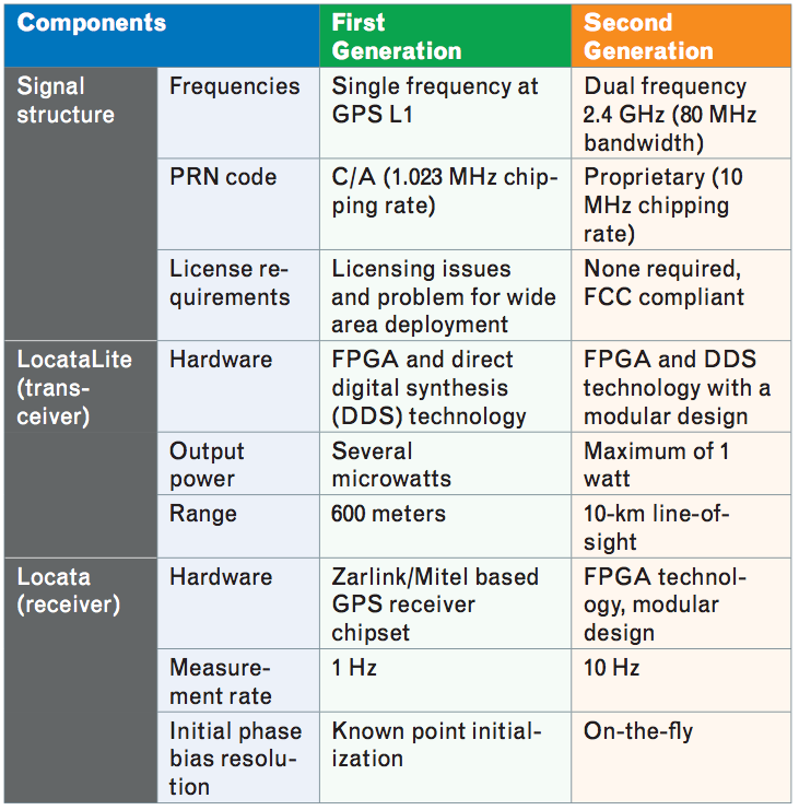
In TABLE 1, the key characteristics of the two generations of Locata technology are listed. Using 2.4 GHz not only means the frequency is license-free, but also permits transceiver output power of up to 1 watt, which means greater operating distances (up to 10 kilometers). Using dual-frequency signals changes the initial phase-bias resolution from known-point initialization to on-the-fly (OTF), where the initial phase bias is resolved while the receiver is moving. The higher chipping rate (10 MHz) results in less pseudorange multipath error, because the delay in a reflected signal will rarely be more than two chips. The 10-Hz measurement rate allows relatively high velocities of the receiver.
Table 1. Specification summary of Locata’s first- and second- generation systems.
In terrestrial-based RF-based positioning, multipath error is more severe than with GPS, because the terrestrially transmitted signal arrives at the receiver at a very low (typically less than 10 degrees) or even a negative elevation angle, which can result in severe multipath signal fading. In the second-generation Locata system, spatial and frequency diversity techniques are employed. Spatial and frequency diversity are two of the three types of diversity principles (the other being polarization) that are common practices in terrestrial RF communications to mitigate against signal fading. The LocataLite transceiver uses two spatially separated (usually in the vertical) antennas, which transmit two signals at different frequencies. This gives a cluster of four diverse signals transmitted from one LocataLite. With this diversity technology, Locata kinematic positioning in moderately obstructed environments can provide centimeter-level quality with 100-percent coverage, as well as consistent geometry and high reliability. The Locata’s multipath mitigation technology is very important and relevant to this project, because the operational environments are often vegetated or wooded.
Triple Integration
As discussed in the preceding sections, there are both advantages and disadvantages to every navigation sensor. GPS and Locata have high positioning accuracy in open or moderately obstructed environments, but they are sensitive to signal blockage such as the case in dense forests, urban canyons, deep mine pits, and indoors. In contrast, INS is totally autonomous — that is, independent of external signal sources — and has high output rate for position, velocity, and attitude, but its unaided navigation error grows rapidly with time.
The most common data-processing tool to integrate GPS and INS is the Kalman filter, which forms the basis for multi-sensor integration in this research. The basic Kalman filter applies to linear system models. Therefore, several variations were developed to cope with the non-linear navigation model, such as the extended Kalman filter and the unscented Kalman filter.
The following discussion of the integration of the GPS/INS/Locata sensors is focused on two aspects: 1) the system state selection, and 2) the measurement model or integration model that decides which information to pass to the filter.
The error state vector consists of a nine-dimensional navigation error state sub-vector (three for the position, three for the velocity, and three for the orientation), an accelerometer error state sub-vector, a gyroscope error state sub-vector, and a three-dimensional gravity disturbance state sub-vector. Of course, other sensor error models can be considered for the gyroscope and accelerometer sensors, such as a combination of random constants, first-order Gauss-Markov variables, scale factors, and so on. In this case, the state space could have a dimension of more than 30. The objective is to adjust the sensor error model later based on experimental results (if needed). However, because of the limitations of observability, it is not yet known whether an augmented error state vector would give better results.
When integrating INS hardware with other sensors, the sensors cannot share the same physical location, which would be ideal from a theoretical point of view. Knowing the spatial relationship among the sensors is important to ensure the highest possible navigation performance. The displacement vectors or mounting biases are offsets, also referred to as lever arms, from the center of the IMU to the centers of the other sensors. These lever-arm parameters may be included in the Kalman filter and thus can be estimated. However, if the lever arms are precisely measured during the assembly of the system, they do not need to be included in the filter as estimable parameters.
For multiple sensor integration in a Kalman filter, there are essentially two types of general models: loosely coupled and tightly coupled. The loosely-coupled model uses a decentralized filter that has several sub-filters to process the sub-systems independently. In other words, the Kalman filter solutions from the sub-systems are combined in an overall Kalman filter that provides the integrated navigation solution. In contrast, the tightly-coupled model uses a single main filter to process the output of all sensors. In GPS/INS integration, tightly-coupled systems have obvious advantages in environments where GPS signals are frequently lost, because they can rely on the other sensor(s) when GPS positioning becomes impossible.
In the tightly-coupled model, the raw observations of all sensors will be input to the main filter. For GPS and Locata, the primary observations will be the carrier phase measurements, as code (pseudorange) observations cannot provide the required accuracy. High-accuracy GPS positioning needs to address the issue of carrier-phase ambiguity. The ambiguity can be treated as an unknown in the Kalman filter, but it may take several minutes to resolve the ambiguity using GPS alone. Using certain ambiguity resolution techniques, however, the ambiguity can be resolved outside the main filter in the GPS/INS high-precision (carrier-phase) integration filter. Note that if the ambiguity were to be resolved within the filter, this would increase the number of states of the filter. For the GPS component, ionospheric delay should be included for applications that cover a large area. Ionospheric delay can be resolved using network-based differential techniques,
but it will affect the ambiguity resolution for single baseline differential positioning if it is not included in the local solution. The filter is designed either to use, or not to use, ionospheric delay, which can ensure flexibility to accommodate network-based and single-baseline differential positioning.
As mentioned above, the measurement model in the tightly-coupled model is based on the raw observations. For GPS and Locata, the observations will be the carrier-phase observations. The approximate values for the linearization of the GPS and Locata measurement equations are provided by the INS navigation solution.
The GPS carrier-phase ambiguity is solved independently outside the Kalman filter with OTF techniques. The GPS differential positioning coefficient matrix remains the same regardless of whether or not a network-based differential technique is used. For velocity determination, the double-differenced Doppler observation is used to eliminate the clock error rate as an unknown (because it is difficult to model this in the filter). The initial carrier-phase bias of the Locata is also not included in the filter, because it can be resolved instantaneously with dual-frequency data in the Locata second-generation system.
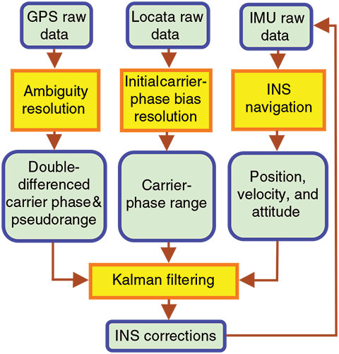
The implementation of the filter will be flexible, so adjustments can be made to account for actual environmental conditions. The filter is designed with an open interface and is modular in structure, so that components can be added (or removed) from the model. In open-sky areas, GPS is sufficient for system positioning, so only its observations need to be processed. In moderately obstructed environments, GPS and Locata observations will be processed. In this case the number of GPS observation equations is limited and sometimes will be less than four. FIGURE 1 illustrates the flowchart of the triple-integration of GPS, INS, and Locata.
Figure 1. Workflow of the integrated GPS/ INS/Locata system.
Field Tests
For experimental purposes, we used a dual INS, based on a navigation grade unit and a tactical grade unit. In addition, a Locata receiver and a dual-frequency GPS receiver were placed on a vehicle at Locata’s Numeralla Test Facility (NTF) near Canberra, Australia. This test site features both open-sky and obscured environments, allowing for testing the system’s performance under truly challenging scenarios. The test was repeated by mounting the devices on an autonomous electrical car, driven on the UNSW campus. In both cases, the separation between the rover and the terrestrial transmitters was between a few tens of meters to several kilometers. The GPS and Locata data were processed separately (for testing the internal consistency) as well in a hybrid solution, resulting in few-centimeter-level accuracy per coordinate, depending primarily on GPS availability and the geometry between the rover and Locata devices, as well as the level of multipath fading.
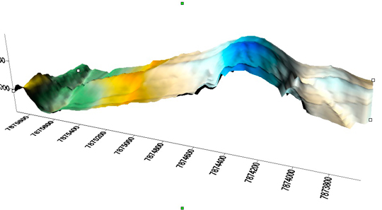
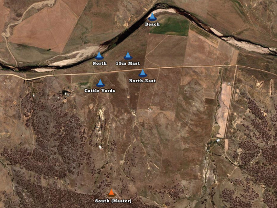
Test 1: NTF. The first integration test was conducted at the NTF on March 17, 2008. The NTF covers an area of approximately three hundred acres (2.5 kilometers × 0.6 kilometers) and is ideally suited to real-world system testing over a wide area. At the NTF, a number of LocataNet configurations are possible through the installation of permanent antenna towers. The network configuration used for this experiment is illustrated in FIGURE 2.
Figure 2. NTF: LocataLite network.
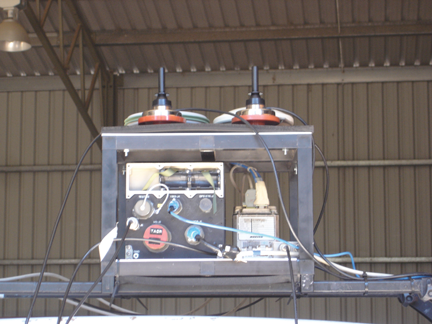
Before the test, a special mounting platform was designed and built. The platform, shown in FIGURE 3, consists of a two-level metal frame. The bottom level can accommodate two inertial measurement units, while the top level can hold up to four antennas. The platform can be easily attached to either the roof of the NTF test vehicle or to the body of UNSW’s small electric car (described later).
Figure 3. Devices setup for the NTF test.
The devices used in the test include two dual-frequency GPS receivers (one used as the rover receiver and the other as the base station), one navigation grade INS, and one Locata rover unit. The GPS antenna and the Locata antenna were mounted with the INS together on the top of a truck. The GPS data rates were set to 1 Hz. The average length of the GPS differential baselines was about 1.2 kilometers. The GPS observation conditions were good during the testing period. The Locata data rate was set to 10 Hz, while INS data rate was 256 Hz, and both were synchronized with the GPS time using SNAP-Lab-developed time synchronization devices based on field-programmable gate array (FPGA) technology.
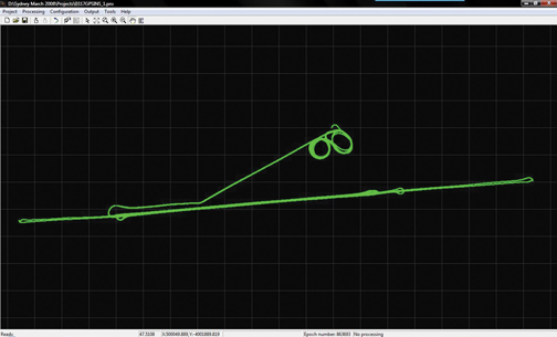
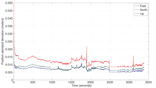
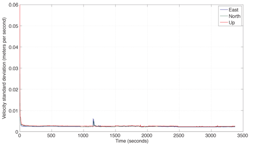
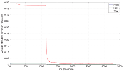
The GPS/INS data were first processed in tightly-coupled mode. The trajectory is depicted in FIGURE 4. The standard deviation of position, velocity, and attitude are shown in FIGURES 5-7 respectively.
Figure 4. The trajectory of the vehicle in the NTF testFigure 5. The standard deviation of position in the test.Figure 6. The standard deviation of velocity in the test.Figure 7. The standard deviation of attitude in the test.
In Figures 5-7, it can be seen that the standard deviations of position and velocity are less than 0.02 meters and 0.01 meters per second respectively. The standard deviations of pitch and roll angles are less than 0.001 degrees as well as that of yaw, which is less than 0.01 degrees after the vehicle starts to move, at about the 1500th second.
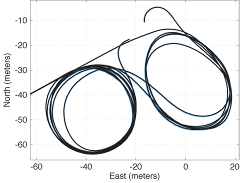
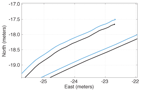
The Locata data was post-processed using Locata’s Integrated Navigation Engine (LINE). It provides an unsmoothed single point position using carrier-phase measurements. The initial ambiguity bias was resolved using the data from the GPS carrier-phase position. Following this initialization, the Locata solution was computed independently of GPS. A 15-meter tower LocataLite location in the vicinity of the start and end of the test (indicated by the “figure eight” pattern in FIGURE 8) allowed sufficient geometry for 3D positioning using Locata. For the rest of the data where there was insufficient vertical geometry, GPS height aiding was used. Figures 8 and 9 show the independent Locata and GPS solutions (without lever arm correction) for the section of the trajectory in the vicinity and the end of the test, respectively. The Locata solution compared to the GPS solution to within a few centimeters for the entire trajectory.
Figure 8. Section of trajectory showing independent Locata solution (black) vs. GPS (blue) with no lever-arm correction.Figure 9. End of trajectory showing independent Locata solution (black) vs. GPS (blue) with no lever-arm correction.
To test the GPS/INS/Locata integration, some GPS observation epochs were deleted to simulate two GPS blockages from seconds of week 94100 to 94250 and from 94500 to 94600. The INS standalone navigation errors with this deleted GPS data were about 8 meters and 2.6 meters, respectively.
In the final GPS/INS/Locata integration test, Locata compensated for the missing GPS data. The integration result was almost identical to the GPS/INS integration result obtained with the original GPS observed data clearly showing that the Locata system could seamlessly replace GPS in this scenario.
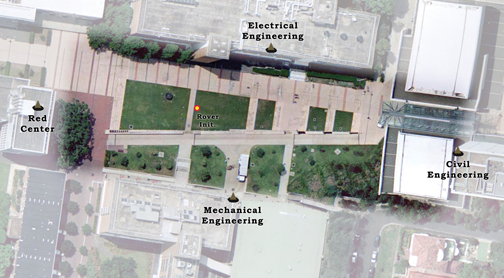
Test 2: Electric Car. Early in 2007, UNSW researchers established a permanent LocataNet on the university campus to provide a research and test facility at UNSW devoted to the Locata technology. The LocataNet setup at UNSW is illustrated in FIGURE 10. It consists of four dual-frequency LocataLites situated on tops of four buildings surrounding a lawn test area. The master LocataLite is on the Civil Engineering building and the other three LocataLites are synchronized to it.
Figure 10. LocataLites on the UNSW campus.
Currently, to be able to obtain a carrier-phase position solution with Locata, the initial ambiguities need to be resolved by initializing the rover receiver on a known position. For this purpose, a point in the middle of the test area was surveyed, and the coordinates were used to initialize the Locata receiver.
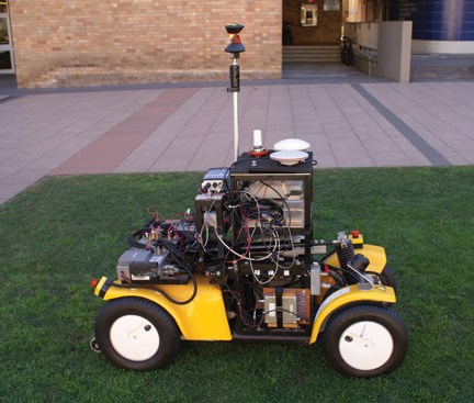
SNAP Lab has developed a small electric car that can be driven using an attached handheld controller (see FIGURE 11). The controller enables the car to move in both forward and reverse and to steer the front wheels.
Figure 11. The electronic car used in the test.
For these tests, the same mounting platform as the one used in the previous experiment allowed all the sensors and ancillary equipment to be attached to the car. For this experiment, we used the following equipment: a Locata receiver, two GPS receivers, a tactical grade INS, a 360-degree prism (tracked by a robotic total station), and two time-sync FPGA data-logging devices.
The starting position was the known point in the middle of the Locata network. The car was then driven in a circular path three times before finishing back at the starting position.
During the test the raw data stream from the Locata receiver, the GPS receivers, and the INS were recorded using the time-sync data-logging devices. In addition, a robotic total station (RTS), which was set up at the edge of the test area, automatically tracked the prism position (the data was recorded internally).
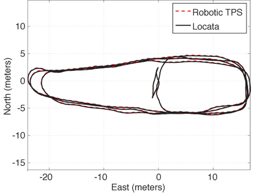
The Locata data was post-processed using LINE to give a single point unsmoothed carrier-phase solution. The initial ambiguity bias was resolved using the data from the GPS carrier-phase position. Following this initialization, the Locata solution was computed independently of GPS. Where there was insufficient vertical geometry (at the very west end of the trajectory shown in FIGURE 12), GPS height aiding was used. The Locata-only solution and the RTS result are shown in Figure 12. The two solutions compare to within a few centimeters of each other.
Figure 12. The trajectory from the Locata-only and robotic total station solutions.
We then carried out the integrated GPS/INS processing. To test the GPS/INS/Locata integration, two GPS outages were simulated by simply removing the data from the GPS file, between seconds of week 103703 and 103713 and 103834 and 103844, respectively.
We then carried out the integrated GPS/INS processing. To test the GPS/INS/Locata integration, two GPS outages were simulated by simply removing the data from the GPS file, between seconds of week 103703 and 103713 and 103834 and 103844, respectively.
In comparison to the original GPS/INS integration, the standalone INS solution has errors of about 35 meters and 12 meters during the first and second outages, respectively.
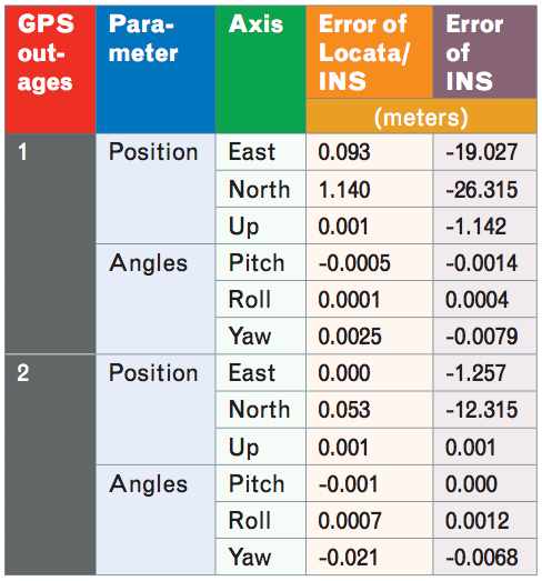
The Locata/INS integration significantly reduced the navigation error during the GPS outages, as summarized in TABLE 2.
Table 2. The difference between the Locata/INS solution and the original GPS/ INS solution
From Table 2 it can be seen that 3D position differences between the Locata/INS and the original GPS/INS integration result have been reduced to 1.143 meters and 0.053 meters during the two GPS outages, respectively. However, the improvement in the accuracy of the attitude angles is not obvious because a 10-second GPS outage is not long enough to cause a significant INS drift.
Concluding Remarks
The test experiments described here are a demonstration of the proof-of-concept of a triple-integration GPS/INS/Locata system. The navigation results indicate that this sensor combination may support navigation in GPS-denied environments, as long as some partial view of the LocataLites within the network is available. Further development of this triple integration system is being undertaken.
Acknowledgments
The research is funded by the Australian Research Council. This article is based on the paper “A Hybrid System for Navigation in GPS-challenged Environments: A Case Study,” presented at ION GNSS 2008, the 21st International Technical Meeting of the Satellite Division of The Institute of Navigation, Savannah, Georgia, September 16-19, 2008.
Manufacturers
The Numerella test equipment included Locata devices, a Honeywell H-764G navigation-grade INS, a Boeing (now Systron Donner) C-MIGITS II tactical grade INS, and a Leica System 1200 dual-frequency GPS receiver. The UNSW campus test equipment included Locata devices, an Omnistar GPS receiver, a Leica MC500 GPS receiver, a Boeing C-MIGITS II INS, a Leica GRZ4 360-degree prism, and a Leica robotic total station TCRP 1203+.
CHRIS RIZOS is a graduate of the University of New South Wales (UNSW), Sydney, Australia, where he obtained a Ph.D. in satellite geodesy. He is head of the School of Surveying and Spatial Information Systems at UNSW.
DOROTA BRZEZINSKA is a professor and leader of the Satellite Positioning and Inertial Navigation (SPIN) Laboratory at The Ohio State University (OSU) in Columbus, Ohio. She received her M.S. and Ph.D. in geodetic science from OSU.
CHARLES TOTH is a senior research scientist at OSU’s Center for Mapping. He received a Ph.D. in electrical engineering and geo-information sciences from the Technical University of Budapest, Hungary.
ANDREW G. DEMPSTER is the director of research in the School of Surveying and Spatial Information Systems at UNSW.
YONG LI is a senior research fellow at the SNAP Lab. He obtained a Ph.D. in aerospace engineering.
NONIE POLITI is a graduate of the School of Electrical Engineering and Telecommunications at UNSW. He obtained a Bachelor’s degree in Telecommunication Engineering and an M.Eng.Sc. in electronics.
JOEL BARNES is director of navigation R&D for Locata Corporation and is also a senior visiting research fellow at the SNAP Lab.
HONGXING SUN is a post-doctoral researcher in the SPIN Lab. He received a bachelor’s degree in geodesy and M.S. and Ph.D. degrees in photogrammetry from Wuhan University, China.
LEILEI LI is a Ph.D. candidate at Chongqing University, China. He is also a visiting Ph.D. student in the SPIN Lab. He received an M.S. degree in instrument science and technology from Chongqing University.
FURTHER READING
• Locata
“Locata: A New Technology for High Precision Positioning” by N. Politi, Y. Li, F. Khan, M. Choudhury, J. Bertsch, J.W. Cheong, A. Dempster, and C. Rizos in Proceedings of ENC-GNSS 2009, the European Navigation Conference, Naples, Italy, May 3-6, 2009.
“Deploying a Locata Network to Enable Precise Positioning in Urban Canyons” by J.-P. Montillet, G.W. Roberts, C. Hancock, X. Meng, O. Ogundipe, and J. Barnes in Journal of Geodesy, Vol. 83, 2009, pp. 91–103 (doi: 10.1007/s00190-008-0236-7).
“High Accuracy Positioning Using Locata’s Next Generation Technology” by J. Barnes, C. Rizos, M. Kanli, A. Pahwa, D. Small, G. Voigt, N. Gambale, and J. Lamance in Proceedings of ION GNSS 2005, the 18th International Technical Meeting of the Satellite Division of The Institute of Navigation, Long Beach, California, September 13–16, 2005, pp. 2049–2056.
“A Positioning Technology for Classically Difficult GNSS Environments from Locata” by J. Barnes, C. Rizos, M. Kanli, and A. Pahwa in Proceedings of IEEE/ION PLANS 2006, the Position, Location, and Navigation Symposium, San Diego, California, April 25–27, 2006, pp. 715–721.
• Integrated Positioning
“Seamless Navigation Through GPS Outages – A Low-cost GPS/INS Solution” by Y. Li, P. Mumford, and C. Rizos in Inside GNSS, Vol. 3, No. 5, July/August 2008, pp. 39–45.
“Ubiquitous Positioning: Anyone, Anything: Anytime, Anywhere” by X. Meng, A. Dodson, T. Moore, and G. Roberts in GPS World, Vol. 18, No. 6, June 2007, pp. 60–65.
“Photogrammetry for Mobile Mapping: Bridging Degraded GPS/INS Performance in Urban Centers” by T. Hassan, C. Ellum, S. Nassar, W. Cheng, and N. El-Sheimy in GPS World, Vol. 18, No. 3, March 2007, pp. 44–48.
“Development of a GPS/INS Integrated System on the Field Programmable Gate Array Platform” by Y. Li, P. Mumford, J. Wang, and C. Rizos in Proceedings of ION GNSS 2006, the 19th International Technical Meeting of the Satellite Division of The Institute of Navigation, Fort Worth, Texas, September 26–30, 2006, pp. 2222–2231.
“An Integrated Positioning System: GPS + INS + Pseudolites” by Y. Yi, D. Grejner-Brzezinska, C. Toth, J. Wang, and C. Rizos in GPS World, Vol. 14, No. 7, July 2003, pp. 42–49.
• Kalman Filtering for Integrated Systems
“Tightly-coupled GPS/INS Integration Using Unscented Kalman Filter and Particle Filter” by Y. Yi and D.A. Grejner-Brzezinska in Proceedings of ION GNSS 2006, the 19th International Technical Meeting of the Satellite Division of The Institute of Navigation, Fort Worth, Texas, September 26–30, 2006, pp. 2182–2191.
“Low-cost Tightly Coupled GPS/INS Integration Based on a Nonlinear Kalman Filtering Design” by Y. Li, J. Wang, C. Rizos, P. Mumford, and W. Ding in Proceedings of NTM 2006, the National Technical Meeting of The Institute of Navigation, Monterey, California, January 18–20, 2006, pp. 958–966.
• Data Time Synchronization
“A Time-synchronisation Device for Tightly Coupled GPS/INS Integration” by P. Mumford, Y. Li, J. Wang, C. Rizos, and W. Ding in Proceedings of IGNSS Symposium 2006, International Global Navigation Satellite Systems Society, Gold Coast, Australia, July 17–21, 2006.