Trimble announced that it has acquired privately-held Gatewing of Gent, Belgium, a provider of lightweight unmanned aerial vehicles (UAV) for photogrammetry and rapid terrain mapping applications. The acquisition broadens Trimble’s industry-leading platforms for surveying solutions. Financial terms were not disclosed.
According to the announcement, UAVs in combination with photogrammetry are an emerging technology providing an innovative platform for flexible aerial imagery acquisition. Easy to use and flexible, UAVs provide users the ability to create orthophotos and Digital Surface Models (DSM) from aerial imagery for mid-sized areas previously only accessible at higher costs and with longer planning cycles. UAVs are used in a variety of applications including preliminary surveys for corridors and rights-of-way, volumetric surveys, high-level topographic surveys, land fill inspection, and much more.
Trimble reports that Gatewing’s solutions include the X100 UAV and Stretchout desktop software for digital image processing and analysis. The X100 is an ultra-light, 2 kg (approximately 4.4 lbs) class UAV that allows fast and simple image acquisition. It consists of an airframe; an integrated GPS, inertial system and a radio; a 10 megapixel camera; and battery. Using the Trimble Yuma tablet computer, a predefined area is planned and the flight of the UAV is fully automated from launch to landing. The terrain is mapped through parallel flight paths and consecutive, overlapping camera shots during flight. The ground control station (GCS) is used to monitor the mission and allows an on-site image quality check. In addition, the GCS provides the operator with the option to intervene and abort the flight if needed. The image set consists of a number of digital images that are tagged with the GPS coordinates.
Gatewing’s Stretchout desktop software uses advanced computer vision technology which automates raw image processing to deliver georeferenced orthophotos and accurate DSM. As an alternative to the desktop software, users can upload images to Gatewing’s cloud solution, which automatically processes the images based on the users’ requirements. After a few hours, users can download their georeferenced orthophotos and DSMs from the cloud server including feedback about the results for quality assurance.
“The combination of UAVs and low-altitude photogrammetry as an image collection platform opens up new opportunities for surveyors to use aerial imagery for the rapid acquisition of high-density geospatial data,” said Anders Rhodin, director of Trimble’s Survey Business. “We are excited to add Gatewing’s unique aerial mapping system to Trimble’s portfolio of survey solutions.”
“The Gatewing team is excited about the new ownership,” said Maarten Vandenbroucke, CEO and one of three founders of Gatewing. ”For Trimble to see the value in unmanned aerial systems for surveying and mapping applications means that the industry is truly ready for this exciting new technology. We are enthusiastic about how UAVs can revolutionize the landscape and open a complete new spectrum in remote sensing applications. I believe that being a part of Trimble will accelerate the pace in which UAVs will further be adopted by professionals.”
The Gatewing business will be reported as part of Trimble’s Engineering and Construction segment.
Unmanned Aerial Vehicles (UAVs), or as they are becoming known Unmanned Aircraft/Aerial Systems (UAS), are in the news now almost every day. As UAV/UAS applications become more and more sophisticated, and operators seek to integrate them into commercial undertakings, the prospect of civil certification and unrestricted access to U.S. airspace is becoming a near-term possibility. This article discusses current UAV/UAS GNSS navigation capabilities and how this could change in the future.
Recently I’ve become involved in looking at civil certification requirements for UAV/UAS GNSS receivers and discovered the prospect that these air vehicles could be operating alongside regular manned aircraft, or at least within sectors of the same airspace. This might sound a little daunting, especially for people who fly civil transport aircraft and helicopters, but the powers that be are intent on insuring the safety and security of our airspace systems with UAS, and it’s taking a lot of brain power to devise ways forward.
New systems seem to be advertised on a regular basis, and development has given way to production and fielding for many of them. Manufacturers like Boeing/Insitu, Yamaha, IAI/Malat, and General Atomics are working in the UAV/UAS marketplace alongside other major players like Raytheon, Thales, Sagem, and a host of other companies who have carved out niches in what seems to be an exploding commercial and military business.
So, where exactly are we today with navigation and GNSS on UAVs? Well, you first have to know the vehicle and its applications. A few examples might help. There are a couple of well publicized vehicles which have become quite successful in civil applications. If we first consider the Yamaha RMAX remotely piloted helicopter, the most prevalent application appears to be crop spraying in Japan and elsewhere in Asia. So GPS RTK is a great navigation system for RMAX, especially since this is a commercial application and its unlikely that there would be jamming or spoofing to disrupt the receiver or its radio links. Low-altitude, short-range from the controller — contained and relatively safe, you might think.
RMAX – Crop Spraying
In a relatively short-range application like RMAX, existing high-precision GPS technology seems to work just fine, especially if an operator is nearby and able to take over manual control if anything untoward goes wrong. This is a very successful commercial vehicle and several hundreds have been sold since its introduction in 2003.
Another system which has sold in large numbers is the Boeing/Insitu ScanEagle. No wheels on this baby — launch is via a high-power catapult. This system also navigates with a commercial GPS receiver, which is key to the unique auto-capture system used for retrieving the UAV. The vehicle is flown in low-level horizontal flight to intercept a cable suspended from a portable 50-foot gantry. Precision guidance involving GPS RTK ensures capture when the UAV wing flies into the cable and a hook on the wing snags the cable. Lift is immediately dissipated and the UAV can be recovered by ground crew as it dangles on the cable.
Any summary of “typical” UAS would be lacking without mention of the General Atomics MQ-1 Predator and its bigger brother, the MQ-9 Reaper. These vehicles carry not only INS, but also a high-end commercial GPS receiver used for take-off and landing.
While these systems are clearly war machines, there are also some in semi-commercial service, including border patrol. If you’ve ever seen one of the many U-tube videos of take-off or landing, it’s hard to see much difference in performance from that of, say, a B-737 or any civil transport. And one of the contributing reasons is that the UAV uses somewhat similar inertial-GPS terminal/landing guidance that civil transports use — a mix of GPS and inertial. We could probably guess that these aircraft also carry a P-code military GPS for remote operations in hostile territory, where enemy jamming and/or spoofing might throw the commercial receiver for a loop. But most UAVs would likely take off and land in a “friendly” environment, so commercial GPS will probably provide the precision needed for these operations.
Now, let’s fast-forward to a time when local law-enforcement wants to patrol or search over populated areas where people are used to seeing manned patrol fixed-wing aircraft, or more likely, police helicopters. Or the local TV station wants to fly cameras overhead for a news story in the making using an unmanned vehicle, or when crop spraying in Kanas or Iowa uses UAS because it has become more economical than using manned aircraft. With the success of UAS in military applications, it’s clear that there is a growing demand to introduce them into civil operations, in a somewhat similar way that GPS transitioned from being a purely military system into extensive commercial use.
How can we make sure these systems operate safely in civilian airspace? Well, that’s an answer the Federal Aviation Administration (FAA) has been seeking for several years. Like most FAA rule-making, the agency turns over a good part of the formulation of technical requirements to the Radio Technical Commission for Aeronautics, more commonly referred to as the RTCA. The RTCA serves as a Federal Advisory Committee, supported by around 400 government, industry, and academic organizations from the United States and around the world. The FAA normally commissions RTCA to develop consensus-based recommendations, which are passed onto the FAA, who normally turn them into regulations which govern aircraft operations in the National Airspace System (NAS).
An RTCA Special Committee (SC) is formed with predetermined terms of reference by asking industry, government, and others if they will provide knowledgeable, contributing members who will meet, discuss the issues, and propose practical technical solutions. These proposals are developed, mulled over, and refined, sometimes over many years and, when found to be acceptable through joint RTCA management and FAA review, they are given to the FAA, which turns them into operational or technical regulations. The game starts for a new system like UAS with the formulation of Minimum Aviation System Performance Standards (MASPS).
For UAS, RTCA “stood up” special committee SC-203, which appears to have been up and running since around 2004. Two guidance documents have been developed and published — RTCA DO-304 “Guidance Material and Considerations for Unmanned Aircraft Systems” and RTCA DO-320 ‘Operational Services and Environmental Definition for Unmanned Aircraft Systems.” Both are essential work the committee had to cover first before they were able to get to MASPS for UAS. And yes, there are lots and lots of acronyms, abbreviations, and special terms in this world of unmanned aircraft.
I attended a recent meeting of SC-203 at the RTCA offices in Washington, D.C. My motivation was to discover what the game plan might be and how it could relate to GNSS avionics and systems. What struck me immediately is that there are a lot of organizations and lots of people who are interested enough to attend — more than 100 government, industry, and other representatives turned up for the opening session.
We listened to a summary of what’s been achieved, what the work plans were for the three-day meeting, and what the target schedule was for release of UAS MASPS. A lot’s been done, but the pressure is high to get to regulations soon so commercial operations can get going. UAS operate in civil airspace today, but largely through temporary Certificates of Authorization (CoA) — often with an observer and even a chase aircraft.
Four Working Groups (WG) have been established: Systems Engineering, Sense and Avoid, Human Factors, and Command and Control. I found what I was looking for in WG1 Systems Engineering when we finally on the last day got to talk about navigation. Navigation is seen as a principle function at the same level as sense and avoid, manage, and command and control, but little work seems to have been done to date in this area. I became a little alarmed at one stage when it seemed that there was a bias against GPS as it “can suffer from jamming and interference.” Sure, but other systems have their failings — like rate of position/velocity drift for inertials — but the beauty of an integrated navigation suite is that one system overcomes another’s potential weaknesses. After all, GPS is THE approved navigation system around which the navigation in the NAS is now built — virtually all manned aircraft use GPS in North America! Admittedly we have back-up systems like VHF Omnidirectional Range (VOR) and Distance Measuring Equipment (DME), which are cornerstones of the NAS airway navigation system, but GPS is the chosen way forward and is key to the FAA NextGen future airspace architecture.
So, jumping to the obvious question — when will we have MASPS and when will UAS be able to fly when they want in U.S. airspace? Not as easy as that, I’m sorry to say. This is a huge task — just consider what it took to build up all the rules and regulations that allow the many thousands of commercial aircraft operations we see every single day in North America and around the world. Years and years of work went into building safeguards and proving their effectiveness. Now we have vehicles that are piloted from remote locations with limited visual “awareness” of their surroundings, by pilots sitting at motionless consoles that appear more like video games than cockpits. But progress is being made, with the objective that no special operational considerations are desired beyond how manned aircraft are currently operated in civil airspace.
So UAS have to step up to this challenge if they want unrestricted airspace access, and that probably means significant changes in vehicle and systems design, qualification, and certification. Given that a large number of UAS use GPS RTK in take-off and landing modes, its likely that we’ll see new qualification standards for these receiver systems. Radio links will have to meet safety requirements, and receivers will probably have to meet more stringent requirements, similar to which aircraft receivers are currently qualified. For your regular land-survey RTK system, there are no requirements which push us to the same software qualification standards as airborne systems. But it’s hard for probabilistic RTK algorithms to meet these current qualification standards that demand 100% repeatability and known outcomes, not likelihood, as in carrier-cycle ambiguity resolution. Things will improve as new constellations come on line, and we can approach certainty with many more measurements from many more satellites.
Leica Viva RTK System
The U.S. government is pushing hard, however, to get to civil standards for UAVs. A recently announced competition is seeking to establish six new test facilities for UAS with one of the objectives to support certification objectives, alongside the ongoing technical committee activities. NASA is also planning a UAS demonstration with a primary objective to qualify an unmanned system for operations in U.S. controlled airspace.
Nevertheless, wherever RTK is essential to operations, it’s quite possible that UAS landing/launch and take-off/recovery could be limited to “company facilities” outside of controlled airspace where regular manned aircraft fly watchfully by.
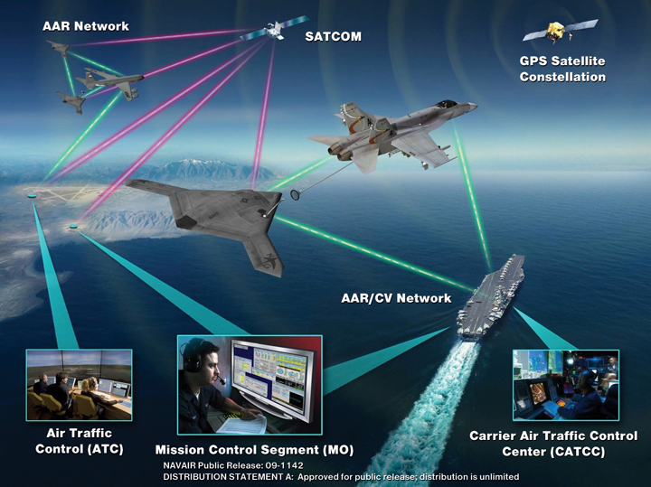
Figure 1. Autonomous air refuleing operational view.
By Alison K. Brown, Dien Nguyen, and Paige Felker, NAVSYS Corporation, Glenn Colby and Frank Allen, PMA-268 NAVAIR
An alternative precision GPS architecture, Precision RELNAV, enables an airborne tanker plane and a Navy unmanned combat aircraft to navigate independently to a high degree of precision without requiring carrier-cycle ambiguity resolution using precision GPS ephemeris updates to a tightly coupled GPS/inertial solution onboard each aircraft. The solution rivals that of conventional relative kinematic techniques while providing more robust positioning that reduces message traffic between aircraft and does not require a long filtering time.
Naval Unmanned Combat Air System (N-UCAS) is the U.S. Navy’s program to demonstrate technologies and reduce risk for unmanned, carrier based strike and surveillance aircraft. The Unmanned Combat Air System Carrier Demonstration (UCAS-D) program is specifically maturing technologies for unmanned carrier operations and Autonomous Aerial Refueling (AAR). Successful demonstration of UCAS-D technologies provides for transition and risk reduction to future unmanned and manned programs.
A key enabler for N-UCAS is the ability to perform AAR so that the N-UCAS can support long duration missions. As shown in Figure 1, the intent is for AAR operations to mirror current manned Aerial Refueling operations as much as possible and to operate using existing Navy probe and drogue and US Air Force boom receptacle refueling methods.
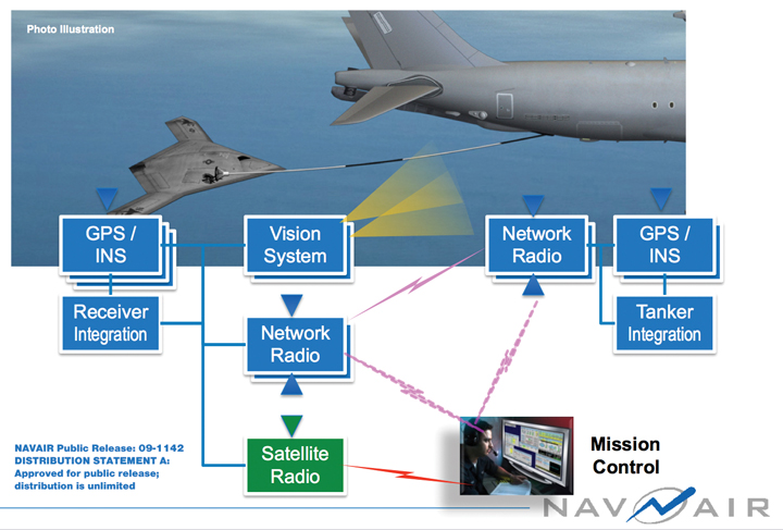
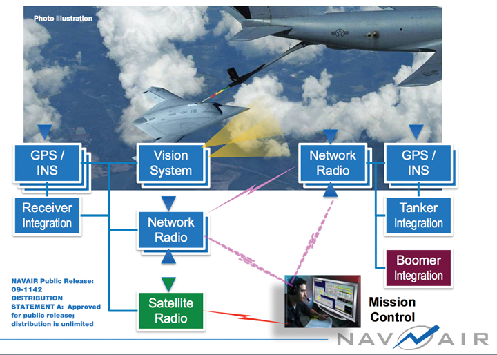
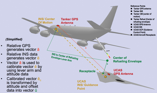
The planned refueling architecture for probe and drogue and boom-receptacle refueling developed by PMA-268 is shown in Figure 2 and Figure 3. For both of these architectures, the GPS/inertial navigation system on the UAS and tanker are used to calculate a precise relative position to be used by the UAS to approach the tanker from astern. For drogue systems, the final connection to the basket is performed using aiding from a laser-based drogue positioning system. In addition, an optional machine vision system is used to aid both methods of refueling from the receiver. Under the UCAS-D demonstration program testing is being conducted with surrogate aircraft to verify the CONOPS procedures and performance of the precision GPS/inertial navigation solution alternatives being evaluated. NAVSYS is supporting this program through a Small Business Innovation Research (SBIR) contract and is demonstrating a Precision-RELNAV (P-RELNAV) tightly coupled GPS/inertial solution that improves the robustness of the relative navigation solution as described in the following sections.
The first method that PMA-268 implemented for computing a relative GPS solution used the GPS/inertial integration approach illustrated in Figure 4. The inertial navigation solution from both aircraft was used to calculate the relative inertial vector e that is used for the real-time AAR guidance. The tanker’s raw GPS observations are also passed over the data link to the UAS where a relative kinematic solution is calculated to derive the carrier-phase based relative position between the aircraft, a. This approach relies on solving for the integer carrier cycle ambiguities on the observations from the two aircraft using the same algorithms that were previously developed for use in performing GPS precision approach and landings on the carrier. The precise GPS relative position is then applied to calibrate the inertial derived relative position and the resulting GPS/inertial solution is used to calculate an offset to the center of the refueling envelope (u) for guidance of the UAS to connect to the receptacle.
Figure 4. Precision-GPS relative GPS positioning.
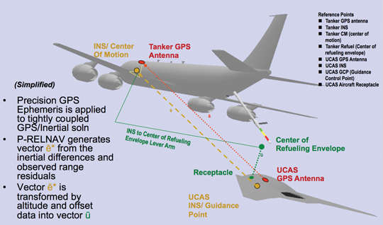
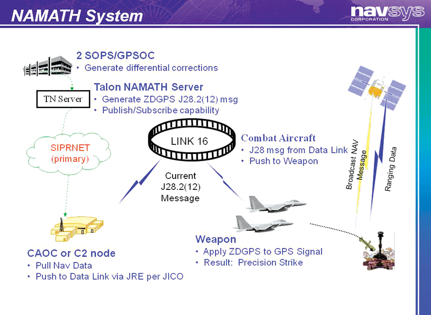
With the P-RELNAV approach shown in Figure 5, Precision GPS Ephemeris data is provided to both aircraft across the tactical data links using the NAMATH system. As shown in Figure 6, NAMATH provides global services across military tactical data links through the Joint Range Extension (JRE) to provide real-time corrections to the GPS system errors using Zero-Age Precision GPS Ephemeris data, which is refreshed by the GPS Control Segment every 15 minutes. The NAMATH system is currently being used operationally by the U.S. military to improve navigation accuracy and also precision weapons delivery.
Using the PGE corrections significantly reduces the errors on the GPS observations allowing the GPS/inertial solution to rapidly converge and not exhibit step changes during satellite transitions from the GPS system bias errors. The GPS/inertial Kalman Filter on the tanker is used to observe the residual errors from the GPS satellites being tracked, and these residuals (δf) are sent from the tanker to the UAS which applies these as an update to its internal GPS/inertial Kalman Filter. As shown below, this final correction sets both the tanker and the UAS on a precise common reference frame resulting in a high accuracy relative position being derived from the vector difference of the two tightly-coupled GPS/inertial solutions (e*).
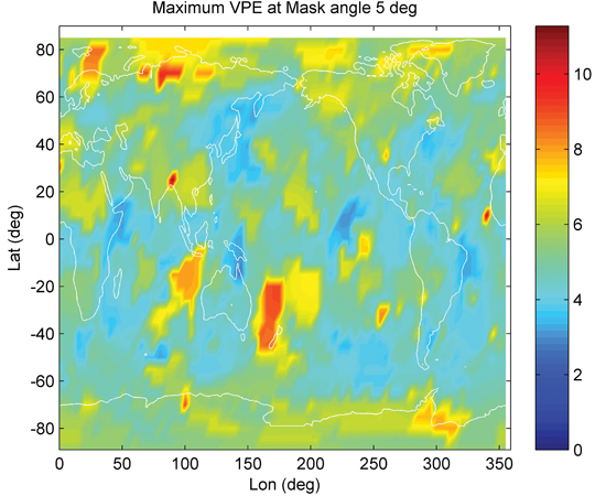
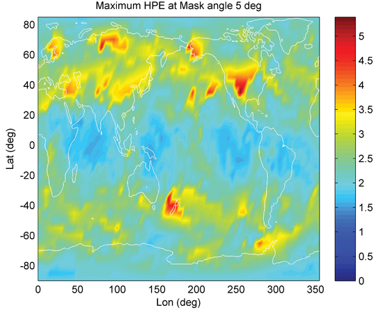
Figure 7 shows the difference in the GPS position that is calculated using the Precision GPS Ephemeris as opposed to the Broadcast Ephemeris. This shows that over a month, there can be peak position excursions as high as 5 meters in the horizontal and 10 meters in the vertical based on the GPS broadcast ephemeris. With a GPS/inertial solution, these bias offsets will cause the solution to “trend” between different position bias offsets whenever the satellite selected set changes. This trending introduces significant errors into the relative inertial vector between two aircraft (e).
Figure 7. GPS Peak Position Errors from Broadcast Ephemeris Offsets (March 2010).
P-RELNAV Flight Test Set-Up
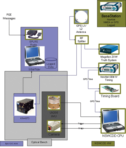
The P-RELNAV performance was tested using data collected on a UH-1 helicopter at Eglin AFB. Two independent GPS/inertial systems were mounted on the equipment plate below the aircraft (Figure 8) and a GPS reference receiver on the ground was used to calculate a kinematic position post-test using a Magellan ZXW receiver on the aircraft as a truth system. The PGE corrections were uplinked to the aircraft through EPLRS for use in calculating a PGE-corrected navigation solution. NAVSYS used recorded GPS and inertial data from a Kearfott KN4073 and a NovAtel/LN-200 inertial system provided by Dahlgren NSWC. The raw GPS (Pseudo-range and carrier phase) and IMU (high rate acceleration and angular rate) data was processed using our InterNav solution and also recorded for post-processing. This data was then played back through InterNav to calculate independent GPS/inertial tightly coupled solutions from the two inertial systems with and without the PGE corrections and to compare the performance of the absolute and relative solutions against the kinematic positioning truth data.
Figure 8. Flight test equipment.
P-RELNAV Flight Test Results
The P-RELNAV algorithms were implemented in our InterNav software package. This has been previously used to generate very high accuracy relative kinematic solutions for providing high-rate Time Space Position Information (TSPI) for instrumenting F-16 aircraft. The InterNav software was upgraded to apply the tightly-coupled GPS updates to the inertial solution using the PGE Zero-Age Differential GPS (ZDGPS) corrections, and also to apply the GPS residual updates (δf) in the UAS Kalman Filter to compute the P-RELNAV relative position solution.
Dual-frequency observations from the GPS receivers were used to correct for the ionospheric group delays in the solution.
The performance of the P-RELNAV solution was evaluated by comparing the results from the two independent inertial solutions for the same location on the UH-1 aircraft. Tests were conducted over multiple flights with the GPS antennas at different locations on the UH-1.
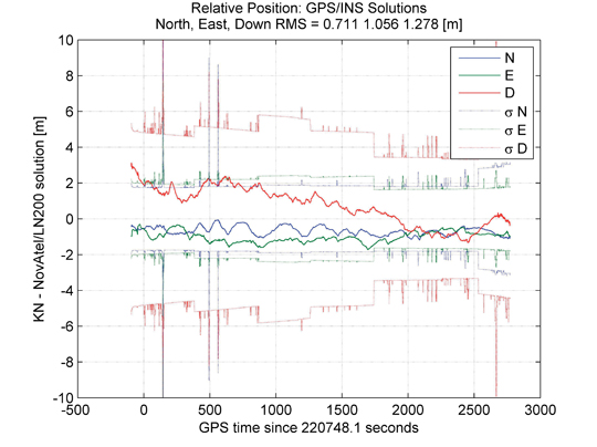
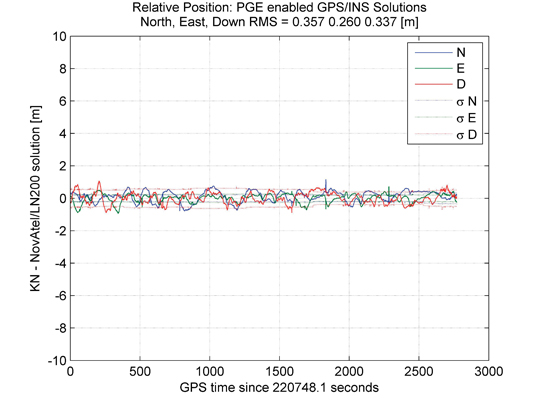
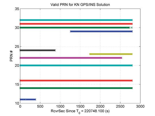
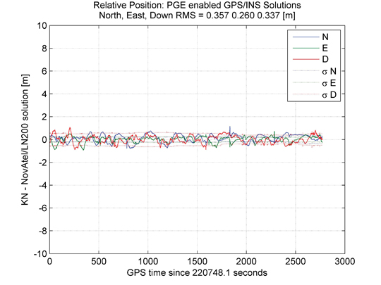
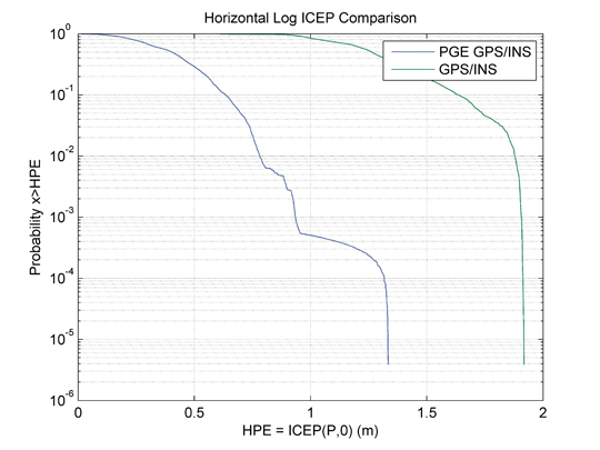
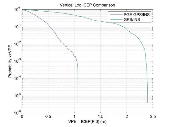
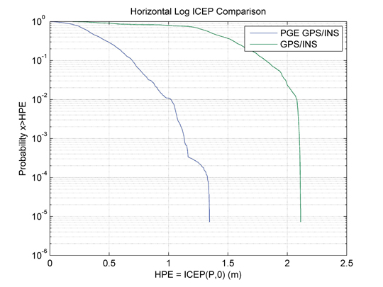
The results from the first flight test are shown in Figure 9 through Figure 13. Figure 9 shows the GPS/inertial results during the flight with a tightly-coupled solution but without PGE corrections. Figure 10 shows the GPS/inertial results during the flight with a tightly-coupled solution but with PGE enabled. Figure 11 shows the satellite visibility during the flight test. These plots show that the satellite geometry changes, dramatically affecting the inertial position covariance, whenever the satellites used in the solution change. The inertial filters these errors, but the relative solution is biased and drifts resulting in over 2 meter errors. In Figure 12 the same plot is shown when the PGE corrections are applied. This shows that the relative position error has been reduced to better than 1 m per axis and 35 cm 1-sigma. For flight critical operations, such as AAR, minimizing position excursions is essential. Figure 13 and Figure 14 show a statistical measure of the percentage of time that the data exceeds a horizontal or vertical threshold. This shows the benefit of the PGE corrections in removing GPS excursions caused by satellite ephemeris errors from the navigation solution. (See the Appendix for a definition of the Inverse Circular Error Probable (ICEP) metric and its comparison with other statistical measures).
Figure 9. Flight 1: Relative position of KN and NovAtel/LN200 GPS/INS solutions.Figure 10. Flight 1: Relative position of KN and NovAtel/LN200 PGE enabled GPS/INS solutions.Figure 11. Flight 1: Valid PRNs used in KN GPS/INS solution.Figure 12. Flight 1: Relative Position of KN and NovAtel/LN200 PGE enabled GPS/INS solutions.Figure 13. Flight 1: Horizontal ICEP comparison for PGE enabled GPS/INS and GPS/INS solutions.Figure 14. Flight 1: Vertical ICEP comparison for PGE enabled GPS/INS and GPS/INS solutions.
Since both GPS receivers used in the test had a reasonably clear view of the sky, they were both tracking the same satellites. In the AAR CONOPS, the UAS approaches the tanker from below and so will have some satellites obscured from view by the tanker (see Figure 4). In this case, the use of different satellites can significantly increase the relative position error when PGE corrections are not available. In the case shown where one satellite was forced as a drop-out, the non PGE corrected vertical error grew to 4 meters for the relative solution.
Further improvements in the P-RELNAV performance will be achieved using the residual (δf) update mode in the InterNav Kalman Filter to set the estimated observation residuals for the common satellites to the same values for the UAS and Tanker GPS/inertial filters. This mode is currently being tested and the results will be presented in a follow-on paper.
Figure 15. Flight 1: Horizontal ICEP plot for PGE enabled GPS/INS and GPS/INS solutions. Different satellites tracked by the receivers.Figure 16. Flight 1: Vertical ICEP comparison for PGE enabled GPS/INS and GPS/INS solutions. Different satellites tracked by the receivers.
Conclusion
The P-RELNAV solution has the following advantages over using a conventional relative kinematic positioning solution in meeting the Automated Aerial Refueling precision positioning requirements.
Fast initialization — does not require time for carrier ambiguity cycles to be resolved.
Robust operation during satellite obscuration by the tanker — is not dependent on common satellites being maintained in view between platforms.
Insensitive to loss of carrier lock — does not require cycle ambiguity reinitialization if carrier lock is lost during the UAS approach to the tanker.
Work is proceeding on testing the P-RELNAV solution. Additional test data is being collected for performance evaluation under the UCAS-D demonstration program using dual aircraft as surrogates to demonstrate the P-RELNAV performance and compare the benefits of the P-RELNAV tightly coupled approach with the PGPS kinematic solution.
This work was sponsored under NAVAIR contract N68335-10-C-0094. The authors gratefully acknowledge the support of PMA-268 and the assistance of NSWC Dahlgren in collecting the flight test data and providing the truth reference for the P-RELNAV analysis.
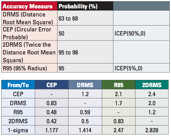
Appendix: Inverse Circular Error Probable (ICEP)
For safety-of-life applications, the statistic of the excursion events, for example when a horizontal error is outside the safe error bound, is often more important than the knowledge of the percentage of points that are within a smaller error bound, such as CEP or DRMS. These excursion, or low probability, statistics can be examined with the Inverse Circular Error Probability (ICEP) function. The ICEP provides the horizontal position error (HPE) with a specified probability that a result could be outside this value. An optional input to the function is a filtering time constant, with the filter applied to the time-series horizontal error data before calculating the ICEP. This separates the effect of bias errors from short term noise errors that could be filtered (for example with an inertial unit) from the HPE.
HPE = ICEP (P%, τ)
Where
HPE= Horizontal Position Error value [m]
P% = Percent of total horizontal errors (x) that are larger than HPE
τ = filter time constant to reduce short term white noise
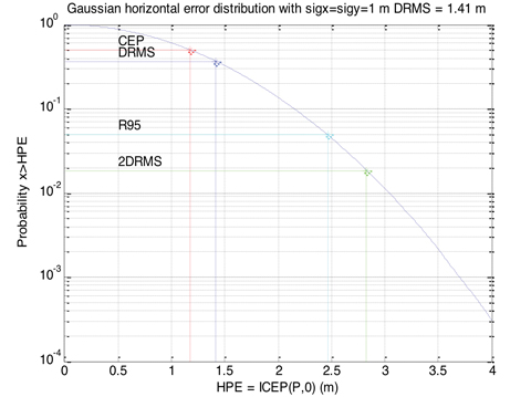
Note that the Circular Error Probable (CEP) which is the radial value that encloses 50% of the positioning results is closely related to ICEP, with
CEP = ICEP(50%, 0)
Also the R95 which is the radial value that encloses 95% of the positioning results is related to ICEP, with
R95=ICEP(5%,0)
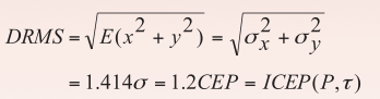
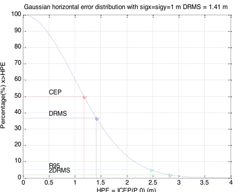
Other common statistics used are the DRMS and 2DRMS values which are defined below, are also related to ICEP through the following equations.
For a Gaussian, uncorrelated error distributions with sigma of one meter in the range and azimuth axes, the ICEP is shown in Figure A-1 in blue. For each horizontal position error value, the ICEP gives the percentage of the distribution that has larger errors. Also shown on this plot are the CEP, DRMS, 2DRMS and R95 values which match the 1-sigma scale factors shown in the table above. Figure A-2 is the same data with a log10 plot. In this plot the y-axis is probability rather than percent. This plot is useful for examination of outlier behavior, as it shows low probability events more clearly.
Figure A-1. ICEP(P,0) for a Gaussian Distribution with 1 m 1-sigma.Figure A-2. Log Scale ICEP(P,0) for a Gaussian Distribution with 1 m 1-sigma.
Alison Brown is president and chief executive officer of NAVSYS Corporation, which she founded in 1986. NAVSYS Corporation specializes in developing next generation Global Positioning System (GPS) technology. She has a Ph.D. in mechanics, aerospace, and nuclear engineering from UCLA.
Dien Nguyen works for NAVSYS Corporation as a research engineer specializing in Kalman filtering estimations, kinematic positioning, and related navigational optimization techniques. He holds an M.S. in electrical engineering from Clemson University.
Paige Felker is a research engineer in the Algorithms and Analysis group at NAVSYS Corporation. She holds an M.S. in aerospace engineering from the University of Texas at Austin.
Glenn Colby is the chief architect for the Navy Unmanned Combat Air System at the Naval Air Systems Command in Patuxent River, Maryland. He has led the research, development, and testing of advanced aircraft, navigation and communications systems for more than 26 years. He received his B.S. in aerospace engineering with honors at the University of Virginia in 1984.
Frank Allen is the technology manager for the Navy Unmanned Combat Air System at the Naval Air Systems Command. In the last 16 years he has worked in management of research and development of advanced aircraft navigation and communications systems. Frank received his M.S. in physics from Northeastern University.
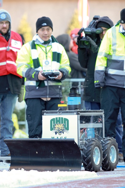
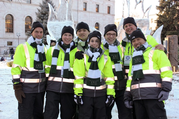
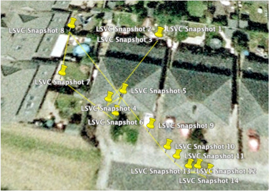
An Ohio University team won the Institute of Navigation (ION) Satellite Division’s second annual ION Autonomous Snowplow Competition. The competition was held January 26-29, at Rice Park in downtown Saint Paul, Minnesota, in conjunction with the 126th Saint Paul Winter Carnival.
Sponsored by The Institute of Navigation Satellite Division and held in cooperation with the ION North Star Section, the ION Annual Autonomous Snowplow Competition is a national event open to college and university students, as well as the general public, that challenges teams to design, build, and operate a fully autonomous snowplow using state of the art navigation and control technologies to rapidly, accurately and safely clear a designated path of snow.
Six teams participated during the four-day competition, each using unique vehicle design approaches.
Teams included students, partners from private industry and faculty advisors from Dunwoody College of Technology; Miami University (Ohio); Ohio University; The University of Michigan, Dearborn; and The University of Minnesota.
Teams were judged based upon their cumulative scores earned throughout the competition phases: 75% of the total score was based upon the plowing competition; and 25% of the total score was based upon the presentations and pre-event report.
First place was awarded to Ohio University students Samantha Craig, Ryan Kollar, Kuangmin Li and Pengfei Duan with support from faculty advisors Frank van Graas, Woulter Pelgrum and Maarten Uijt de Haag. The first place prize included $3,000 and a golden snow globe trophy.
Second place was awarded to Miami University students Chad Sobota, Mark Carroll, Robert Cole, Mark Stratis, with support from student advisors Steve Taylor, Ryan Wolfarth and Harrison Bourne and faculty advisors Jade Morton, Peter Jamieson and Janet Burge. The second place prize included $2,000 and a silver snow globe trophy.
Third place was awarded to the University of Michigan (Dearborn) students Angelo Bertani, Zach DeGeorge, Mark Lawrence, Doris Kotori, Alf Williams, with support from student advisors Benjamin Craig, Jhonatan Ferrer, and faculty advisor Narasimhamurthi Natarajan. The third place prize included $1,000 and a bronze snow globe trophy.
In addition, the first place team, Ohio University, will be invited to display their winning snowplow during ION GNSS 2012 Conference September 17-21, 2012 in Nashville, Tennessee.
Sponsors of the second annual ION Autonomous Snowplow Competition included Lockheed Martin Corporation, ASTER Labs, Inc, Honeywell, Inc., Alliant Techsystems Inc., U.S. Bancorp, Hitching Post Motorsports, Space Exploration Technologies Corp., and The Toro Company.
The Third Annual ION Autonomous Snowplow Competition will be held in January 2013 at the Saint Paul Carnival, St. Paul, Minnesota.
The First Place team from Ohio University. Photo: Ohio University
Nav On Time, a French Company located in Toulouse, has successfully completed a trial campaign of its Mow-By-Sat precision guidance on a commercial lawnmower. In August, the prototype of a GPS-guided robot lawnmower was installed on a golf driving range near Toulouse and tested in real conditions of use, day and night, maintaining a 25,000 square meter lawn since then. In a previous campaign, the mower covered more than 2.2 million yards — equal to1,250 miles or 2,000 kilometers — in 2,100 hours. (See videos of the mower in action at www.youtube.com/DSnavontime.)
With such a success under its belt, Nav On Time is negotiating with different lawnmower manufacturers to bring a product to market. The autonomous lawnmowers already on the market, including machines commercialized by research partner BelRobotics, use underground wired perimeters for delimiting the lawn by an electromagnetic signal, the strength of which is measured by a mower-embedded sensor to determine its distance to the lawn’s limit. But that wire, and its required installation, are technical barriers for a lot of potential customers. Nav On Time is one of the companies developing solutions to get rid of the perimetric wire yet still be able to guide the mower autonomously with accuracy and efficiency.
Between January 2009 and June 2010, Nav On Time coordinated the Mow-by-Sat project, a research and development effort that received funding from the European Union’s Seventh Framework Programme (FP7/2007–2013). Partners included Belrobotics of Belgium, a large lawn-maintenance robot manufacturer, and the University of Catania in Sicily, Italy, through its robotics research department.
The Mow-by-Sat project (www.mow-by-sat.eu) was also undertaken to support development of a GNSS-based navigation and guidance system integrated into an autonomous lawnmower, paving the way for industrialization and commercialization of GNSS applications for a domestic service robot operating outdoors. Beyond this concrete application, the project aimed to increase the adoption of GNSS technologies in robotics applications, studying the benefits of European GNSS (especially EGNOS and Galileo).
Mow-By-Sat uses a virtual fence to replace the wired boundary traditionally used in robot lawnmowers, which provides better flexibility for defining and modifying a mowing area. Mow-By-Sat enhances the machine’s efficiency by a factor of three, as full steering substitutes for the random operation mode, the company said.
Built around a European GNSS L1 automotive receiver, the u-blox T, Mow-By-Sat uses L1 fixed / floating real-time kinematic (RTK) techniques. A tight coupling between the RTK positioning firmware and the guidance application software aids the mower’s precision. Nav On Time compared it to the challenges of aviation, where the required navigation performance depends on the flight phase.
In its patented architecture, the module embedded in the rover is dumb, and the ground-based station acts as a remote control, ensures traffic management between several machines, and serves as a gateway for remote services such as installation, supervision, and surveillance, all accessible from the Internet. Nav On Time developed both the positioning firmware and guidance application software.
According to Nav On Time CEO Michèle Poncelet, Mow-By-Sat offers significant competitive advantages to the machine manufacturer compared to expensive RTK solutions now on the market. She cited:
easy customization because of its open architecture,
an affordable solution for small and inexpensive mobile machines,
a technology enabler for replacing human-controlled and energy-consuming machines with smaller and cheaper machines that have a smaller carbon footprint.
With six Engineers, Nav On Time, founded in 2007, is offering a product line dedicated to precision control solutions for small and inexpensive mobile machines, under a business-to-business model through industrial partnerships. According to Poncelet, its market stretches from human controlled machines (precision agriculture or crane collision avoidance) as driver’s assistance, to unmanned machines (autonomous lawnmowers, other unmanned ground vehicles, intelligent vehicles, and more generally service robots) with full steering.
Other applications envisioned by Nav On Time include a golfball retrieval robot for driving ranges, a beach cleaner robot, and a surveillance robot — any application that requires passing through a pre-determined area in a methodical and systematic way.
Breaking Ground
It would seem mowing lawns isn’t a beloved pastime, as autonomous lawn mowers have been the subject of numerous research projects. For the past eight years, the Institute of Navigation has sponsored a Robotic Lawnmower Competition as a way to encourage college students to develop autonomous steering techniques. During the second ION Autonomous Lawnmower competition, Frank Van Graas, who accompanied the winning Ohio University team, told GPS World, “The centimeter-level positioning accuracy required for lawnmowers in the contest is actually more difficult than automatically landing an airplane.”
One research project, carried out by Navcom Technology in 2005, resulted in an autonomous mower taking on the precise mowing techniques of baseball stadiums, with its checkered patterns. The Navcom project, documented by Michael Zeitzew in his paper “Autonomous Utility Mower,” used a series of beacons to augment GPS. Two off-the-shelf John Deere utility mowers were modified for X-by-wire control, and fixed navigation beacons were mounted around the stadium. Next, the field boundaries were surveyed and input into a map file, used to create the mower’s mission plan.
“The use of GPS requires good sky visibility,” explained Zeitzew. “In this application, due to the stringent navigation accuracy requirements, an RTK-GPS solution is required, which requires the use of a base station. Because many of the baseball stadiums have high walls and other obstructions around the field, RTK-GPS is inadequate, even with augmentation by (affordable) inertial sensors or odometry sensors. This necessitated the use of alternative technology.”
Navcom fielded two mower systems into professional baseball stadiums, one major league and one minor league. Both systems were used over the course of several weeks during the spring 2005 baseball season, and received positive reviews from the professional groundskeepers, who quickly grew comfortable using the machines. The project proved not only that autonomous mowers are possible even for large-scale sites such as a stadium, but that there is indeed a market for them.
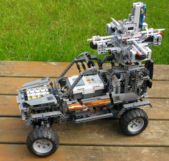
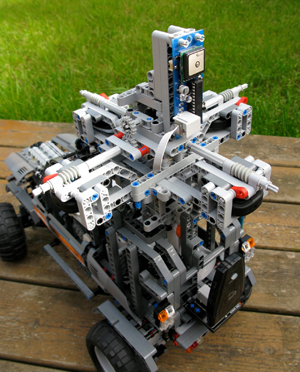
A Google Street Car in miniature uses Dexter Industries’ dGPS sensor (Photo courtesy of Mark Crosbie.)
Aspiring engineers, take note. A company dedicated to building robotic sensors for the LEGO Mindstorms NXT system has released a GPS sensor, and a workbook on how to use it.
John Cole, founder of Dexter Industries, explains that his products are intended for the education market, and are “for engineers, scientists, and those aspiring to be.”
“A few months ago, we developed a GPS sensor for the educational market, called the dGPS,” Cole said. The sensor is sold separately, as a third-party product for the LEGO Mindstorms kit.
The dGPS sensor provides GPS coordinate information to a robot and calculates navigation information. It provides latitude, longitude, time, speed, and heading. It also has powerful navigational calculators that can be used to navigate to target coordinates.
The dGPS sensor uses a Skytraq module. The LEGO NXT has limited computing capability and can’t interface directly with a GPS module, so Dexter Industries developed a micro-controller and software that translates and checks the signal from the GPS, and also performs additional calculations and functions for navigational purposes.
Photo courtesy of Mark Crosbie
“For example, in addition to the standard GPRMC string that comes from a GPS chip, our dGPS sensor can receive destination coordinates from the user and calculate distance to destination and angle to destination so they can be matched against a compass,” Cole said. “Also, because robots of this scale are usually traveling below 15 mph, we developed a more accurate compass function that works on the smaller, slower scale.”
The dGPS hooks directly into any of the four sensor ports on the NXT and can be programmed in NXT-G, RobotC, and LeJOS programming languages.
Cole became interested in the Mindstorms system in 2005 while in graduate school. “It’s an incredible robotics kit that really fits with educational curriculums on the high school and junior high levels. The kit lowers the entrance requirements to get started [in engineering], and because it’s based on LEGO, students are usually comfortable getting started with it. It’s deceptively simple, though; the Mindstorms robot can be used to do some pretty powerful stuff.”
Cole’s company had developed a few other sensors for education, including a solar kit and a pressure and temperature sensor, but focused on developing a GPS sensor, Cole said, because it “would be really fun for kids to start using. In particular, things like autonomous vehicles and mapping vehicles have been really exciting to develop and build with this sensor.”
Not Just for Kids. Mark Crosbie, an adult fan of LEGO (the hobbyists refer to themselves as AFOLs), has built a miniature version of the Google street car that roams the streets to photograph them for Google Maps. The car provides panoramic views from various positions along the streets it travels; data is then made accessible through the Street View feature of Google Maps.
Crosbie created his Street View car using Dexter Industries’ dGPS sensor to record coordinates as it drives along. “John has been very supportive of the project, providing great technical assistance to me as I used his sensor,” Crosbie said.
The idea for a miniature Google street car came to Crosbie when he was playing with the dGPS sensor. “I realized that if I combined this sensor with a robust chassis and a camera then I’d have a LEGO version of the famous Google Street View car. And what if I could then upload the pictures into Google Earth,” writes Crosbie on his website. “It all seemed so easy… How wrong I was!”
As Crosbie explains, his miniature Street View car is controlled manually using a PSPNx sensor to receive commands from any standard PSP game controller — the user presses the triangle button on the controller to capture an image and log the GPS coordinates. The cameras provided the biggest challenge. “The keyfob cameras are very temperamental and difficult to mount into standard LEGO dimensions,” he said.
“Every time an image is captured, the current latitude and longitude are recorded from the dGPS,” Crosbie explains. “The NXT creates a KML format file in the flash file system, which is then uploaded from the NXT to a PC. Opening the KML file in Google Earth shows the path that the car drove, and also has placemarks for every picture you took along the way. Click on the placemark to see the picture.”
Despite technical challenges outlined in his blog, Crosbie is undeterred, and working on another prototype. “I’m already hard at work on version 2.0 of the Street View car for a big event later this year.”
How-to Book. Besides hardware, Dexter Industries offers educational support material. “Just last week, we released a book that introduces middle school and high school students to GPS, and how to develop robots that use the GPS,” Cole said.
The book, Beginning GPS for NXT Robots, provides students with an introduction to the basics of GPS, and includes hands-on activities and tutorials on how to use the features of the dGPS sensor with the robots.
“This workbook was written to bring the GPS system to life and help students understand it, explore it, and find new ways to use it,” Cole said.
4-H program’s GPS/GIS program has started to use the company’s sensors in its curriculum, Cole said, because the sensors hook directly into the NXT robots.
The ION Mini-Urban Challenge, in which high school students compete to navigate a LEGO robotic car through a miniature city, don’t use GPS sensors. Students are provided with a kit that contains six other sensors that detect things such as light, color, and sound.
“We would love to be part of the ION challenge and we’ve tried contacting the organizers just recently,” Cole said. “It would be a great fit to get some students using the GPS in a way that really gets kids engaged in GPS/GIS development.”
A Google Street Car in miniature uses Dexter Industries’ dGPS sensor (Photo courtesy of Mark Crosbie.)A street-view photo captured from the on-board cameras of the mini car. (Photos courtesy of Mark Crosbie.)
Learning how to control a car as a race driver does, at its very limits of handling, can ultimately assist ordinary drivers who enter a turn too quickly or are driving on a wet road and don’t realize when they need to brake. DGPS and inertial sensors drive feedback and feedforward speed controllers on a twisting test track to the top of Pikes Peak.
Stanford professor Chris Gerdes and his Dynamic Design Lab have outfitted and trained a white Audi to roar up the Pikes Peak International Hill Climb, a 12.5-mile racecourse to the top of the 14,110-foot Rocky Mountain summit.
Without a driver.
Officially known as the Autonomous Audi TTS Pikes Peak, the car has been nicknamed Shelley by its crew, in honor of Michele Mouton, the first woman to win the Hill Climb, in 1984, also in an Audi.
The team of graduate and Ph.D. students and Volkswagen’s Palo Alto research lab have spent two years conceptualizing and modifying the car to make the solo climb. They have just returned from tests of the car’s DGPS and other sensors on the course. International [human] racers competed on June 30, with the fastest just missing the course record of 10 minutes, 1.408 seconds, established in 2007, by a mere 10.082 seconds. That’s an average speed of 75 miles per hour over a course with 156 turns, many of them hairpins, an elevation gain of 4,721 feet, and both paved and gravel surfaces. Speeds at the Pikes Peak Hill Climb, often described by drivers as racing against the mountain more than other vehicles, top out around 165 miles per hour.
Shelley, not specifically built as a racecar, does not have the horsepower to hit that speed, but she aims for respectable rates all the same. “We are ultimately going for the fastest time we can get in a TTS and hope to establish that range in September and shoot for it in 2011,” wrote Gerdes from the mountain.
Safety the Goal. The team’s work is a variation on one theme: make Shelley drive faster, smarter — and safer.
“We believe that if we can learn how to control a car at its very limits of handling,” Gerdes said, “then we can also help ordinary drivers who enter a turn too quickly or are driving on a wet road and don’t realize when they need to brake. That’s ultimately where we hope this goes: safety systems.”
“Average drivers sometimes end up involved in road accidents due to their inability to control a vehicle at its limits,” Gerdes and Krisada “Mick” Kritayakirana wrote in a 2009 paper, from which the following results and figures are drawn, “yet racecar drivers routinely operate a vehicle at its limits without losing control. The difference could come from two key characteristics that racecar drivers have acquired.
“First, a racecar driver has the ability to estimate the friction between the tire and the road surface. Second, a racecar driver can utilize all of the actuators to control the vehicle at its limits, such as using the throttle and brakes to steer the vehicle, which could be counterintuitive to a typical driver. If a controller could imitate a racecar driver, perhaps this same concept could be applied to a vehicle safety system to assist drivers when they are on the verge of losing control. The controller could utilize every actuator to assist the driver, and real-time friction estimation could help predict the control authority that each actuator has. The goal of this research is to create a controller that captures these two key characteristics of a racecar driver.”
Feedforward, Feedback. Before entering a corner, a racecar driver anticipates the speed and steering angle that he or she would use. Similarly, in the Gerdes/Kritayakirana research, a feedforward controller is used to predict the speed and steering commands. While cornering, a racecar driver adjusts actuator commands (steering, throttle, and brake) to cope with any disturbances or driver’s perception mismatches (modeling errors). A feedback controller is designed to imitate a racecar driver making corrections during cornering. As a consequence, the desired steering and speed commands are calculated from the sum of feedforward and feedback controllers.
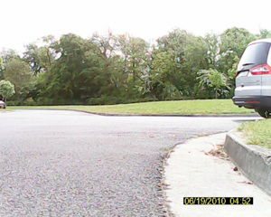
Robustness Tests. At Stanford, preliminary testing of Shelley’s control systems on the student-built P1 by-wire research vehicle provided a proof of concept. As with Shelley, P1’s DGPS and inertial sensors determine path-tracking errors that can be used to implement the steering feedback controller. A large parking lot with gravel over asphalt provided the ideal proving grounds for these tests. The inconsistent surface provided varying friction in the range of 0.4 to 0.6 and therefore presented a control challenge. The steering control had to be robust enough to ensure that this variation did not result in instability and the vehicle spinning.
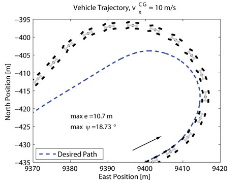
The vehicle trajectory in Figure 1 shows performance of the steering feedback tested in isolation with an arbitrarily chosen constant accelerator input. Because the vehicle enters the curve much faster than the friction between the tire and the road can support, large deviations from the desired path (in this particular case, a maximum lateral error of 10.7 meters, and maximum heading error of 18.73 degrees) occur.
Figure 1. Vehicle trajectory with feedback steering only.
Although it swings wide of the desired path, P1 remains stable and does not spin out. The ability to maintain control of the car even when there is a misjudgment in the friction conditions is vitally important to both the Pikes Peak climb and future safety systems.
Demonstrating the robustness of the steering control both analytically and experimentally on P1 gave the team confidence to use it as a central part of Shelley’s control logic.
Combined Controllers. The current control scheme running on Shelley adds the feedforward steering and both feedforward and feedback speed control elements to the simple steering controller demonstrated in Figure 1.
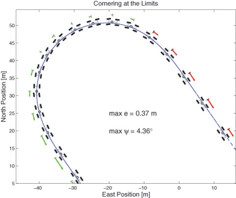
This combination can track the desired path around the corner quite closely, as shown by the trajectory in Figure 2. This plot shows the performance on a rough dirt track with a friction coefficient again between 0.4 and 0.6 and therefore a maximum possible acceleration of between 4 and 6 meters/second2.
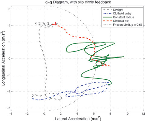
Figure 2. Latest result of TTS on Santa Clara fairground track; arrows indicate amount of vehicle acceleration (in green) or braking (in red).Figure 3. g-g diagram plots longitudinal and lateral acceleration, from tests on a different track, with friction on this surface (.65) somewhat higher than discussed in the text (0.4–0.6).
To demonstrate that Shelley is operating at the limits of friction, a g-g diagram is depicted in Figure 3. These diagrams, which are typically used to evaluate racecar driver performance, plot the longitudinal and lateral acceleration of the vehicle. An expert driver will achieve the maximum possible longitudinal acceleration in braking and the maximum lateral acceleration in cornering.
In transition between braking and cornering, the best drivers will use all available friction, giving the ideal curve a roughly circular shape. The g-g diagram for this test illustrates that Shelley continually operates at the limits of friction. As a result, the curve bears some resemblance to the behavior of an expert racecar driver. More precise comparisons with expert drivers driving the same course are planned for the future.
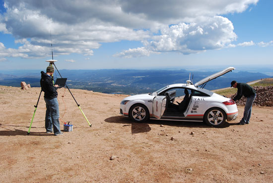
Shelley at rest as crew prepares DGPS base station and checks onboard computer.
A Rich Legacy
Shelley follows in the tracks of other Stanford robot cars such Junior, an autonomous Volkswagen Passat. “Junior was a perceptual challenge,” Gerdes recalled. Junior and its predecessor Stanley, under the direction of Stanford professor Sebastian Thrun, were designed to perceive the environments around them, understand signs and recognize the driving situation of nearby vehicles, then logically respond to what they saw. Both competed in the Defense Advanced Research Projects Agency (DARPA) Grand Challenges.
Stanley and Junior, while possessing a much higher level of autonomy than Shelley and able to handle a range of environments, crept along at speeds well below the average driver’s comfort level, and placed little emphasis on driving dynamics. Shelley is highly focused on the dynamics issue.
“They’re all autonomous vehicles to some extent, but they have very different scopes, and I guess you could say, very different personalities as well,” Gerdes said.
“Can we go around turns as fast as possible, brake at the last possible minute, and accelerate out as soon as we’re steering out of a turn?” Gerdes asked. This became the group’s goal for Shelley.
Rami Hindiyeh had the task of crafting Shelley’s judgment. He writes software designed to mimic a rally car driver’s mind with a series of mathematical analyses that predict how the car should control itself in different situations. He looked at “ways to slide Shelley through turns like a rally car racer would.” Mick Kritayakirana is in charge of the autonomous racing controller to govern Shelley “at the limits, like racecar drivers race on the pavement.”
The Audi TTS’s steering, brakes, gears, and throttle are all controlled electronically, so Shelley required few mechanical modifications to integrate her systems into a controller area network that allows the vehicle’s components to communicate. The network enables the team to individually switch each component from manual to automatic so the team can test its reliability.
Shelley’s most critical components are GPS antennas and receivers coupled to an inertial system that determines speed and sideways motion. The INS controls the car’s direction during GPS signal interruptions, giving up to 200Hz updates on car position.
While the combined effects of Shelley’s systems are complex, the computer in the trunk that processes the data isn’t any faster than one you could buy a decade ago. Most calculations are done separately within the GPS and in the vehicle electronics. “We don’t need a whole lot of computational power to run the driving and racing algorithms,” Gerdes said.
“We have to spend a lot of time trying to make the car listen to what we command,” Kritayakirana added.
The Pikes Peak course was plotted on a GPS map for the car to follow, and based on that information and how much friction the computer predicts, it has an idea of how fast it can take turns at different angles and with varying road surfaces. The computer refines its speed and steering with each test turn to figure out what Gerdes calls Shelley’s “braking point.”
“When a human is driving a car and they see a turn coming up, they can, at a constant rate, so to speak, just try to turn the wheel towards that curve preemptively,” said team member David Hoffert. “And that works because roads are designed with certain mathematical geometric properties that if you do that, [you] follow the path.”
As the team nears the finish line, members continue to closely collaborate with Volkswagen’s research group. They have weekly meetings “where we talk about our current status and evaluate the hardware and software,” said Marcial Hernandez, senior research engineer at Volkswagen. The team aims to have Shelley back on the mountain in September. “We’d really like to send the car pretty close to its capability, certainly much, much faster than people would be comfortable driving unless they were highly skilled racecar drivers,” Gerdes said.
Pre-Race Tests
The team’s trip to Pikes Peak in July enabled the group to experience the International Hill Climb and watch some of the best racers in the world tackle the mountain. Following the hill climb, the project team devoted a couple of days to gathering GPS data on Pikes Peak. This included scouting locations for base stations to broadcast DGPS corrections and determining the availability of corrections at different points along the highway. In addition, the team took measurements of the road boundaries and profiles for developing digital maps of the course.
Line-of-sight issues for the GPS base stations and interference of other voice and DGPS users on the broadcast frequencies used by the team present challenges for racing on the mountain. The group made significant progress on these issues during the June experiments and has scheduled additional GPS testing for July. Travis Wolgram, a test engineer at the Association of American Railroads in Pueblo, Colorado, joined the group to discuss using the High Accuracy National DGPS system in future testing. With a prototype base station now operational at the Federal Railroad Administration’s Transportation Technology Center, 50 miles southeast of Pikes Peak, there is a unique opportunity to harness these corrections for the project.
Shelley should return to Pikes Peak in September, with the goal of driving the entire course slowly and selected segments at full race speed. With proper analysis of this data during the winter months when snow is on the mountain, the team should be prepared to make a full run at race speed in 2011.
Manufacturers
The Autonomous Audi TTS Pikes Peak uses an Applanix POS LV420 GPS and inertial measurement unit, with OmniStar HP service for 10-centimeter or better accuracy, Trimble SPS851 GPS receiver for the base station, two Trimble HPB450 transmitters for RTK signal transmission from the base station, and a Pacific Crest ADL Vantage receiver in the vehicle to receive the RTK corrections.
Tyler Brown is a Stanford undergraduate. An earlier version of this story appeared in the Stanford Daily; it has been updated and expanded here by the Dynamic Design Lab and GPS World staff.
The U.S. Army’s Autonomous Platform Demonstrator, or APD, is a 9.6-ton, six-wheeled, hybrid-electric robotic vehicle currently undergoing developmental and mobility testing at Aberdeen Proving Ground, Maryland. According to an Army statement, the demonstrator vehicle represents the state of the art in unmanned ground vehicle mobility technology.
With its advanced hybrid-electric drive train, the 15-foot-long vehicle, being developed by the U.S. Army Tank Automotive Research, Development and Engineering Center (TARDEC), can achieve speeds of more than 50 mph.
When equipped with its autonomous navigation system, the APD is configured with GPS waypoint technology, an inertial measurement unit and computer algorithms which enable it to move autonomously at speeds up to 50 mph while avoiding obstacles in its path.
“The vehicle has obstacle detection and avoidance technology,” said Jim Overholt, senior research scientist in robotics at TARDEC.
The mobility testing is aimed at advancing and developing the robot’s ability to maneuver at higher speeds while maintaining extreme terrain-ability at lower speeds.
“We’ve run it through courses, slope testing and brake testing,” said Chris Ostrowski, associate director for Vehicle Electronics and Architectures at TARDEC.
The APD is currently testing high-speed maneuverability, such as lane changing. “This is a challenging controls problem with a skid steer vehicle. We want the robot to be stable when performing maneuvers like this, but we also want it to retain the other mobility characteristics that it possesses at lower speeds,” said Ostrowski.
Other mobility characteristics include the ability to climb a one-meter step, navigate a 60-percent slope, and pivot turn in place.
Being a series hybrid-electric vehicle, the APD is propelled by six in-hub electric motors and has a diesel generator which charges its lithium ion batteries.
“The state-of-the-art hybrid-electric drive train is just one of the mobility technologies we are demonstrating with this platform,” said Andrew Kerbrat, APD project manager, TARDEC.
Other technologies being demonstrated include advanced suspension systems, thermal and power management systems, robotic safety systems, and lightweight hull technologies.
“We’ve made a lot of progress with this platform in a short time period. From concept to wheels on the ground was just a shade over two years, and in the eight months since then, we’ve driven almost 3,000 kilometers and have demonstrated 95 percent of the metrics that we were trying to show with this platform,” said Kerbrat.
APD is the mobility platform being used by the Robotic Vehicle Control Architecture, or RVCA Army Technology Objective, also out of TARDEC. Working with PEO-Integration, RVCA has integrated a suite of system control, display and sensing hardware and software onto APD that allow it to be controled real-time by a Soldier, or operate in an autonomous mode.
“It uses a variety of sensors and a Ladar — a laser/radar scanning radar that can detect moving objects at distances,” said Overholt. Additionally, RVCA provides Reconnaissance Surveillance and Target Acquisition capabilities.
“It has a four-meter mast with a sensor ball on top so it goes up pretty high and can see out quite a ways,” said Chris Ostrowski.
“When you combine the autonomy and control capabilities provided by RVCA with the extreme mobility characteristics of APD, it allows the Soldier operator to quickly deploy a mission payload precisely where he wants it, and over some very tough terrain,” said Kerbrat.
“The bottom line is that we are providing the soldier with a significant capability that will assist him in the performance of his mission, while keeping him safer in the process.”
A low-cost, man-portable, reusable unmanned aerial vehicle (UAV) was one of several emerging technologies highlighted at the “Homeland Security: Detect and Protect, Novel Military Technologies for Commercial Use” technology-transfer and federal marketplace event held at the U.S. Army’s Aberdeen Proving Ground (APG) in Aberdeen, Maryland, on April 20.
Hosted by APG, the Maryland Technology Development Corporation (TEDCO), and the Tech Council of Maryland, the event showcased technologies under development in APG?s research labs and testing facilities that can be commercialized by local companies. The UAV garnered interest from the Department of Defense Technology Transfer and Commercialization National Center of Excellence for First Responder Technologies at the University of Pittsburgh; American Aerospace Advisors, Inc.; and CTRL Systems, Inc.
John Condon, mechanical engineer at the Weapons and Materials Directorate, U.S. Army Research Laboratory, led the presentation about the Switchblade UAV, which uses real-time video, infrared imagery, and Global Positioning System technology for surveillance applications. The UAV can conduct overhead intelligence-surveillance-reconnaissance of infrastructure while carrying such payloads as day/night video, high-resolution snapshots, and chem-bio detectors. It can also deliver remote sensors and warheads to preselected areas on the battlefield. The UAV was developed in collaboration with AeroVironment, Inc., a Monrovia, California-based developer of small UAV solutions.
The one-day homeland security program also included presentations focused on available joint research and patent license opportunities, such as Cooperative Research and Development Agreements, and examples of successful partnerships with APG. More than 250 business executives, entrepreneurs, and researchers from 13 states attended the event. Technology-transfer officials from TEDCO were on hand to provide information about state and federal funding programs that support technology-transfer projects.
For more information about this and upcoming technology programs, visit www.marylandtedco.org.