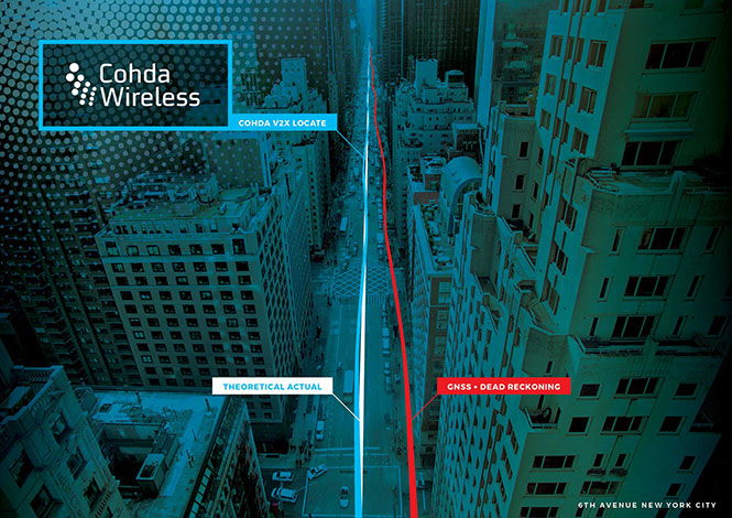
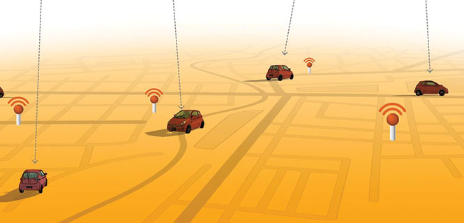
Australian company Cohda Wireless has released a vehicle positioning system to eliminate GPS black spots in “urban canyons” between high-rise buildings.
Using Cohda’s expertise in developing collision avoidance systems for mines, the vehicle-based system, V2X-Locate, can identify vehicle position to sub-meter accuracy in environments that degrade GPS accuracy, such as tunnels, underground carparks and between high-rise buildings.
As well as enhancing current connected vehicles, V2X-Locate delivers a critical component for connected autonomous vehicles (CAV), which will require uninterrupted positioning data to safely navigate on roads, the company said.
Image: Cohda Wireless
Cohda has designed V2X-Locate to enable equipped vehicles to identify their location using existing Smart City V2X (vehicle-to-everything) roadside infrastructure from any standards-based manufacturer.
Cohda Wireless Chief Technology Officer Paul Alexander said V2X-Locate was a globally unique product. “We solve the problem caused by GPS and satellite-based positioning systems not working in all use-cases,” he said.
“If you’re in a major downtown area with tall buildings, or in a tunnel or in an underground parking lot, a GPS system can fail, preventing it from delivering accurate results,” Alexander said. “As well as being inconvenient for current drivers, this is not an option as we enter the era of driverless cars. The V2X-Locate breakthrough is to position the vehicle with sub-meter accuracy by using the existing communications signals produced by V2X Smart City infrastructure deployments. The result is that V2X-Locate can eliminate positioning black spots in city centers where they are most likely to occur.”
Cohda Wireless demonstrated V2X-Locate in a 2017 trial in New York City, where it repeatedly demonstrated sub-meter accuracy while driving along Sixth Avenue, which has the tallest buildings in the Big Apple. Comparably tested GPS-based systems were as much as tens of meters off-course, at times showing cars driving through buildings.
Alexander said Cohda Wireless had designed V2X-Locate by using its experience developing collision avoidance technology for underground mines. “The hardest place to do positioning is one kilometer underground with a cubic kilometer of copper above your head,” he said.
“That’s where V2X-Locate was born,” Alexander said. “Cohda has worked in that area for several years, providing accurate positioning for vehicles where no GPS connectivity is available. We’ve now successfully migrated that technology from mine sites of the outback to the urban canyons of New York City.”
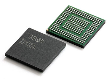
V2X_Locate uses the NXP SAF5400 single-chip modem for V2X. (Photo: NXP)
Both Cohda’s standard V2X onboard units and roadside units use the NXP RoadLINK chipset, which supports V2X-Locate’s highly accurate performance by delivering multipath channel tracking.
After a pre-release international roadshow in October last year, Cohda Wireless received strong interest in V2X-Locate from both Smart Cities and Tier 1 automotive manufacturers. To meet that demand, Cohda Wireless has released a V2X-Locate Evaluation Kit, which contains the system and four roadside unit devices, which equip prospective customers to put V2X-Locate through its paces.
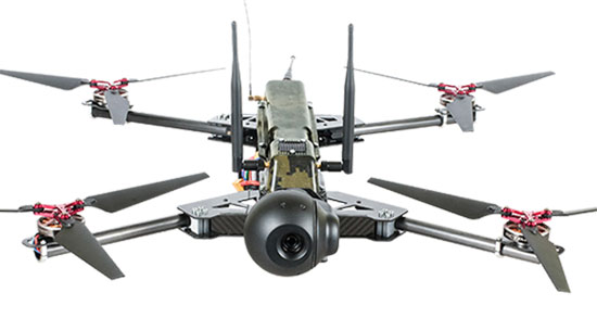
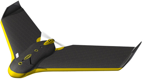
UASTrakker LLC is offering a new guidance system to enable first responders and maritime rescue units to use fully autonomous drones to help locate people lost at sea or in the wilderness.
The company will showcase the system at AUVSI Xponential, scheduled for April 30-May 4 in Denver, Colorado.
UASTrakker emergency response UAV.
The emergency RF beacon tracking system for drones is based on the company’s core patent-pending technology, which uses an internet of things (IoT) edge computer, running the company’s proprietary software and algorithms to deliver an autonomous search-and-rescue (SAR) solution to the professional end user.
UASTrakker integrated systems using an autonomous drone for locating emergency distress beacons, such as a personal locator beacon (PLB) or man overboard beacon.
The UASTrakker system is capable of locating individuals stranded in floods, lost at sea or on land and is expected to be a key component of rescue efforts in maritime rescue, as well as SAR in the wilderness.
How the system works
Trained users operate the UASTrakker-enabled drone by initiating a flight plan to locate the last known position of the target. Once in the air, the drone will scan the emergency radio frequencies used by PLB beacons in distress, and provide situational awareness to first responders using its thermal, infrared and daytime cameras.
When the target is located, the drone stores the GPS coordinates trail, and has the ability to drop lifesaving rescue supplies, or even lower a winch to a person, and rescue them to safety using a heavy lift drone.Ac
During the entire rescue, UASTrakker streams live video into the company’s cloud computing solution of the entire flight, recording the physical location of the incident in day or nighttime conditions. This enables multi-agency collaboration on SAR missions to help locate the victim.
According to the company, the UASTrakker system is compatible with many off-the-shelf drones, so it can be installed on medium-sized multi-rotors for short missions, a hybrid- electric plane for longer missions, or a heavy lifter for difficult to reach areas and rough weather.
At any time, the user can take over control of the flying of the drone, and activate features like the winch. Cellular/satellite technology offers an almost unlimited range of control.
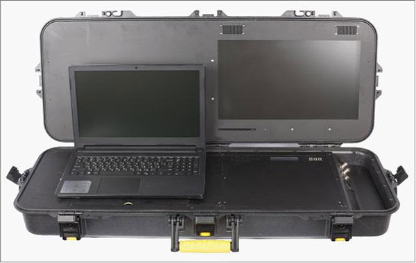
UASTrakker ground control station.
The UASTrakker company is also developing technology for moving ground control stations, so that drones will land more easily on a ship or moving platform like a SWAT vehicle.
The company’s proprietary artificial intelligence (AI)-capable internet console is expected to provide the pilot in command a first-of-its-kind online search grid, with online tools to initiate the autonomous flight search-and-rescue procedure.
When other first responders have downloaded the UASTrakker app, they will have a collaborative map of the rescue operation, showing the drone position and the location of any emergency PLBs within range, while the drone autonomously locates and surveils them until rescuers can arrive.
“A UASTrakker customized rescue drone can be deployed in many different emergency and disaster situations to locate survivors from maritime accidents, avalanches, hikers in distress or to locate stranded people after a natural disaster like a hurricane or flood, by tracking the PLB that is activated by the person in distress,” said Shawn Holmgren, CTO of UASTrakker.
UASTrakker anticipates interest from government agencies including police, fire and rescue, and military, along with private individuals and commercial businesses.
Holmgren will introduce the system at the Association for Unmanned Vehicle Systems International (AUVSI) Xponential show, booth 3233B. The company expects to launch the UASTrakker system by the hurricane season and summer of 2018.
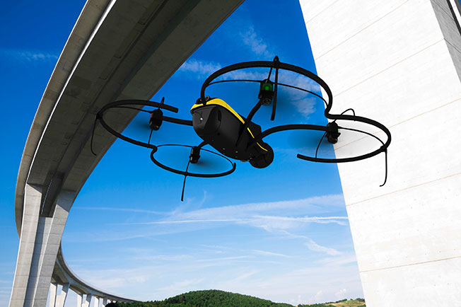
The first European Drone Summit will take place Oct. 15 in Frankfurt, Germany, to bring together stakeholders to discuss the future of drones in Europe. The summit is sponsored by UAV DACH e.V. and Interaerial Solutions of Intergeo.
In addition to being a smart, up-and-coming technology, commercial drones are also an integral part of the digitalisation of business and society. The EU member states have agreed to introduce legislation regulating the operation of unmanned aircraft in Europe that takes into account both economic potential and safety requirements.
The programme will be put together by UAV DACH experts and will explore legal aspects, technological issues and various application areas. Legislators, industry representatives and user groups will meet on the eve of Europe’s largest trade fair for commercial drones.
The following experts will speak (with more to be named later):
Peter van Blyenburgh, UVSI
Max Scheck, Vereinigung Cockpit
Jules Kneepkens, EASA a.D.
Martin Brandenburg, DJI
Andreas Lamprecht, AIRMAP
Jörg Seebach, DeDrone
UAV DACH is an association for commercial unmanned aviation in Europe. It represents the interests of 175+ corporate members from research, manufacturing and application located in Germany, Austria, Switzerland, Italy, Spain and the Netherlands.
The Interaerial Solutions part of Intergeo is the largest commercial drone trade fair in Europe. It takes place Oct. 16-18, also in Frankfurt.
The miniature UAV, smaller than a human palm, zips right to its human target — identified through facial recognition technology — and pierces the forehead with a projectile, for an instant kill.
That harrowing scene takes place in a seven-minute viral video issued by autonomousweapons.org, a non-profit sounding warning bells over potential automation of weapons. Its Campaign to Stop Killer Robots (#BANKILLEROBOTS) seeks a preemptive international ban on “fully autonomous weapons which enable strikes to be carried out without human intervention.”
“Allowing machines to choose to kill humans will be devastating our security and freedom,” warns Stuart Russel, professor of computer science at the University of California at Berkeley, on the video.
What feels like science fiction to those of us raised on the Terminator franchise could be closer than we think. Because of this, a new U.S. Army report emphasizes the need to develop countermeasures against swarming drones and other unmanned weapons.
The Army and U.S. Department of Defense have invested significantly in technologies in response to these threats, often focusing on detecting radio frequency transmissions of the UAVs or their operators.
However, as the report points out, today’s consumer and customized UAS increasingly can operate without radio frequency command-and-control links by using automated target recognition and tracking, obstacle avoidance, and other capabilities enabled by software.
The U.S. Army discusses the pros and cons of autonomous weapons in a June 2017 article in Military Review, saying an international ban should be considered on “fully autonomous weapons with missions that cannot be aborted and that cannot be recalled once they are launched. If they malfunction and target civilian centers, there is no way to stop them.”
Sobering thoughts about a future that may not be too distant.
A roundup of recent products in the GNSS and inertial positioning industry from the April 2018 issue of GPS World magazine.
OEM
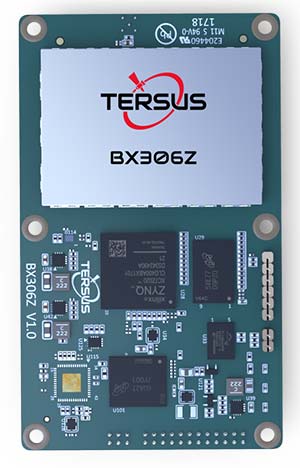
GNSS RTK Board
For OEMs, system integrators
The BX306Z GNSS real-time kinematic (RTK) board has powerful flexibility and compatibility to meet the needs of original equipment manufacturers (OEMs) and system integrators. The BX306Z is a cost-efficient board for positioning and raw measurement output. The board is a compact, multi-GNSS (GPS L1/L2, GLONASS G1/G2, BeiDou B1/B2) RTK module with centimeter-level accurate positioning capability. It is able to integrate with autopilots and inertial navigation units. Log and command is compatible with major GNSS boards.
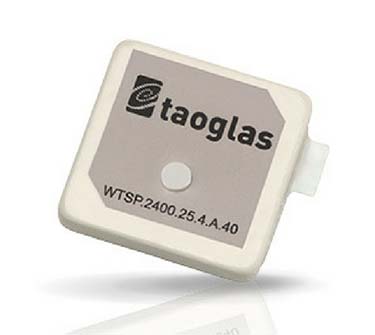
The Taoglas Terrablast antenna line is designed for UAVs and transportation. (Photo: Taoglas)
Rugged antennas
For automotive, drone markets
Terrablast polymer-based patch antennas are 30 percent lighter than their ceramic counterparts and extremely resistant to fracture upon impact. They are designed for the automotive and unmanned aerial vehicle (UAV) markets, where impacts are possible but antenna performance cannot be compromised. The 35-mm GPS/GLONASS/BeiDou patch antenna has high efficiency of more than 70 percent across all bands, improving time to first fix. All Terrablast antennas undergo rigorous temperature, vibration and impact tests, exceed ISO 16750 standards, and are manufactured in Taoglas’ purpose-built facilities in Taiwan and the United States.
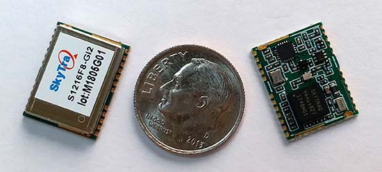
The S1216F8-GI2 is a NavIC + GPS/GAGAN receiver module for emerging intelligent transport systems (ITS) applications requiring NavIC/GPS capability in India. It integrates an L1/L5 RF front-end and baseband processor capable of receiving up to 14 L5 NavIC signals and up to 20 L1 GPS/GAGAN signals simultaneously. With six NavIC signals and three GAGAN signals, it offers 18–23 usable signals, providing improved accuracy in urban canyons. The S1216F8-GI2 is form-factor and pin-out compatible with 12 x 16-millimeter modules, enabling drop-in replacement. NavIC sub-frame data outputs broadcast warning messages for weather alerts and natural disasters. The S1216F8-GI2 is manufactured with ISO/TS 16949 automotive certification.
To meet stringent requirements in harsh environments
The automotive-grade MAX‑M8Q‑01A GNSS module measures 9.7 x 10.1 x 2.5 millimeters and has an operating temperature range from –40° C to 105° C. It is designed to meet the stringent requirements of the automotive market, providing superior positioning accuracy even in challenging environments such as urban canyons. Its temperature range ensures reliable performance in harsh environments, such as when mounted in a car‑roof antenna.
The Teseo APP receiver enables safer autonomous driving. The multi-frequency GNSS receiver chipset is suitable for safety-critical automotive applications and high-accuracy positioning at the decimeter and centimeter levels for precise point positioning (PPP) and RTK applications. By tracking satellites of all GNSS constellations simultaneously on at least two of the frequencies used by each system, ST’s automotive-quality Teseo APP (automotive precise positioning) receiver provides high-quality raw GNSS data for PPP and RTK algorithms, which allows accurate positioning and rapid convergence time worldwide. The receiver monitors the integrity of the satellite data to alert the system if accuracy is degraded for any reason. This permits Tier-1 manufacturers to certify safety-critical systems in accordance with ISO 26262.
Qinertia post-processing kinematic software has been designed to help surveyors get the most of their surveys. After the mission, Qinertia gives access to offline real-time kinematic (RTK) up-to-date corrections from more than 7,000 base stations in 164 countries. By creating a virtual base station near a project, the software delivers the highest level of accuracy without having to set up a base station. An advanced tight coupling algorithm delivers high accuracy and maximizes RTK availability. Trajectory and orientation are greatly improved by processing inertial data and raw GNSS observables in forward and backward directions, especially in challenging environments. With Qinertia, surveyors can quickly identify and solve issues such as mechanical installations or sensor alignment.
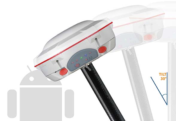
The T300 Plus GNSS receiver is designed for demanding surveying tasks, with full-constellation tracking capability, tilt compensation, 4G/Wi-Fi connection, 8-GB internal memory and an easy survey workflow with Android-based Survey Master Software. It is designed to make collecting accurate data easy and fast, whether done by a beginner or experienced professional surveyor. As an upgrade of the T300, SinoGNSS T300 Plus combines a GNSS board, Bluetooth and adjustable TX&RX UHF, Wi-Fi and 4G modem into one rugged device. Its built-in 4G modem ensures the T300 Plus works with all kinds of continuously operating reference stations (CORS) worldwide. A built-in tilt sensor supports maximum 30° pole tilt and keeps the compensation accuracy within 3 centimeters; the user can check the electronic bubble on the controller for fast surveys in the field.
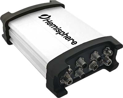
Atlas-capable GNSS receiver for precision 3D applications
The Vector V1000 GNSS receiver is designed for precision marine applications, such as hydrographic and bathymetric surveys, dredging, oil platform positioning, buoys and other applications that demand the highest level 3D positioning accuracies. It provides high-accuracy heading, position, pitch, roll and heave data. The V1000 supports multi-frequency GPS, GLONASS, BeiDou, Galileo, QZSS and IRNSS (with future firmware upgrade and activation) for simultaneous satellite tracking. The receiver is powered by Hemisphere’s Athena real-time kinematic (RTK) engine and is Atlas L-band capable. Based on Hemisphere’s Eclipse Vector technology, the V1000 uses the most accurate differential corrections including RTK and Atlas L-band. It has an integrated display that can be conveniently installed near the operator. The V1000 has heading accuracy of better than 0.01 degree when using a 10-meter antenna separation.
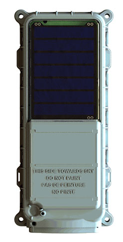
Machine-to-machine (M2M) and internet of things (IoT) device
The SmartOne Solar M2M/IoT device is solar-powered and offers Bluetooth Low Energy connectivity while addressing the growing global demand for reliable and affordable remote monitoring and automated data collection of assets located both within and beyond terrestrial networks. The SmartOne expands the market for remote connectivity to include assets that are otherwise difficult or expensive to reach for power replacement, and lowers the operating cost of monitoring assets being served by legacy SmartOne products. SmartOne Solar’s rechargeable batteries can deliver more than eight years of serviceable life. Without exposure to the sun, a fully charged unit can operate for many months while reporting twice daily. The product’s Bluetooth connectivity allows wireless device configuration and firmware upgrades in the field.
Designed for large-scale surveying and mapping projects
The WingtraOne post-processed kinematic (PPK) drone is the result of collaboration with Pix4D and Septentrio. It is able to deliver orthomosaic maps and 3D models with an absolute accuracy down to 1 centimeter (cm), offering broad coverage and high resolution with ultra-precise accuracy. The WingtraOne can cover 130 hectares (320 acres), equivalent to 240 football fields, in a one-hour flight, and deliver maps at ground sample distances below 1 cm/pixel. Vertical take-off and landing (VTOL) offers hands-free operation and a smoother ride for onboard sensors as well as greater coverage than comparable multi-rotor UAVs. PPK computes ultra-precise geolocations for each image by combining the GNSS data with correction data from a nearby reference receiver. It offers a root-mean-square (RMS) error of 1.3-cm horizontally and 2.3-cm vertically without any ground control points.
DroneHunter is a fully autonomous UAS airspace defense solution. The intelligent robotic aircraft is enabled with TrueView radar designed and engineered for physical remediation of intruder or threatening drones. DroneHunter is an autonomous UAS perimeter detection and protection solution designed to quickly detect, classify and secure against drones and other UAS. When an intruder drone is discovered, DroneHunter can engage autonomously via artificial intelligence (AI)-directed detection, tracking and guidance. Once the rogue drone is identified and the threat level analyzed, DroneHunter safely remediates the threat day or night, at a safe stand-off distance, with no collateral damage. DroneHunter supports multiple drone platforms based on use-case requirements.
By Simon Batzdorfer, Markus Bobbe, Martin Becker and Ulf Bestmann, Technische Universitaet Braunschweig
All images courtesy of the authors.
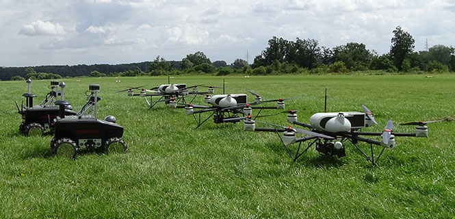
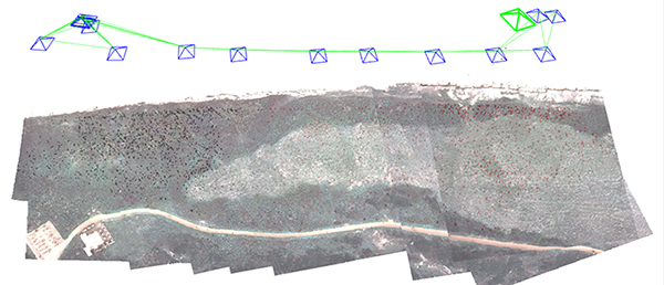
Autonomous vehicles equipped with different environmental sensors, such as optical or thermal camera or a lidar, performed a team survey controlled by a central ground station. The ground station serves as a user interface to define missions and tasks and also to visualize exploration task results online. 2D stitched orthophoto or lidar point clouds are transmitted for display and processing into 3D photogrammetry. Georeferencing data is gathered by an integrated GNSS/IMU positioning system.
In disaster scenarios such as fires, floods or search-and-rescue tasks, good situational awareness is indispensable for responders coping with a complex and often chaotic environment. In most cases, a prior known map data are outdated, and an efficient situational proceeding such as path planning or creation of a search pattern cannot be performed. This information can often only be gathered by manned exploration using ground or airborne systems, with limits on availability.
The research project Automated Navigation and Communication for Exploration (ANKommEn) seeks to create an automated unmanned system to close this gap by providing up-to-date scenario information while increasing the safety of human resources, using unmanned aerial (UAV) and ground-based (UGV) vehicles.
To provide up-to-date information of the desired destination area, all vehicles are equipped with identical positioning and communication hardware complemented by diverse sensors (RGB camera, infrared [IR] camera, lidar) for visual exploration. The visual sensor information is transmitted to a central ground station for visualization and/or analysis. To increase the advantages of the system, the unmanned systems should have a high grade of automation to reduce the workload of the operator so that only basic inputs have to be done by the operator. For example, just by marking a destination area and choosing a predefined task, the mission will be planned automatically, and after the corresponding waypoint-list has been transmitted to the vehicles, the mission will start.
Automated procedures of a UAV in particular require valid position information related to accuracy, availability and continuity. In exploration areas where the UAV operates in low altitude or using a UGV, the reception of the GNSS signal can be degraded by the topology (buildings and such). Using more than one GNSS can increase the availability of position information. Vehicle control, georeferencing environmental sensor data and exploration results all require high-frequency absolute position and attitude and heading information. This data is gathered by fusing GNSS and inertial measurment unit (IMU) data.
OVERALL SYSTEM DESIGN
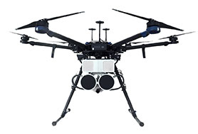
The overall system consists of three UAVs, two UGVs (Opening photo) and a central ground control station. The latter serves as a central human-machine interface to monitor and manage cooperative operation of the UAVs/UGVs by an operator. Based on a priori known map data, exploration areas and tasks are defined and assigned to the UAVs/UGVs and will be updated with actual information of the visual sensors while performing a mission.
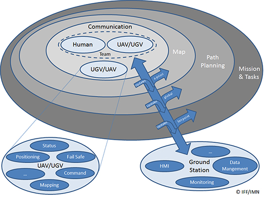
Figure 1 shows the interaction and information exchange between the different vehicles and sensors.
Figure 1. Diagram of interaction and information exchange.
All UAVs/UGVs are equipped with a navigation and communication unit (NAV/COM) and an environmental sensor payload (ENV) unit, including an RGB camera, thermal camera or a lidar respectively.
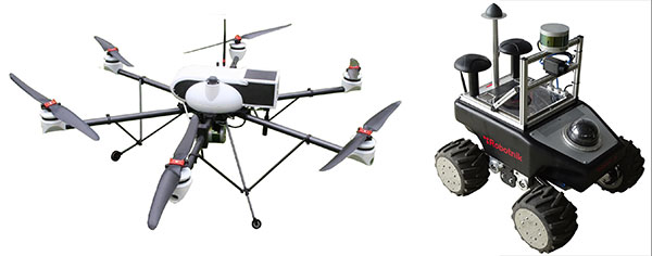
UAV/UGV and Sensor Hardware. The UAVs carry a payload of 2.7 kg (NAV/COM unit, mounted in the upper compartment, and ENV unit mounted under the UAV) and a flight time of up to 30 minutes (Figure 2, left). The payload sensors are carried and stabilized by a two-axis-gimbal. The environmental sensor payload unit is based on three different types of sensors, which are interchangeable between the different UAVs: RGB camera, lidar and IR camera.
For ground-based exploration, two four-wheel-drive UGVs carry a pan-tilt-zoom (PTZ) camera at the top of front chassis (Figure 2, right), and are equipped with a lidar and a thermal camera, or a stereo RGB camera, respectively.
Figure 2. UAV carrying a lidar (left) and UGV carrying lidar and IR camera (right).
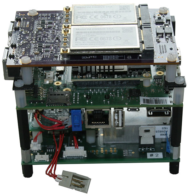
The navigation and communication unit mounted as a stack includes a network processor board for communication and data exchange between the UAV/UGV and the central ground and control station. An embedded processing board provides position calculation and GNSS-NTP-based time server. Data for the position calculation is provided by a custom-designed break-out-board (Figure 3).
Figure 3. Navigation and communication unit.
Data traced by these sensors cannot be sent directly to the ground station because of the huge data amount and the limited bandwidth of the communication link. Therefore, data from the sensors are preprocessed or compressed on a small form-factor personal computer and then transmitted to the ground station.
Ground Station. The ground station is the central device for command, control and visualization of the total system. It provides several options to display the data from the sensors and vehicles and a combination of them, and also provides automated path planning and calculation of the 3D reconstruction (photogrammetry) and online 2D stitched orthophoto.
Software Frameworks. The basic software for determining the vehicle’s state in 3D position, velocity, attitude and heading is established within a modular navigation software framework, with the option to process data of different sensors in real time as well as post-processing for data evaluation and development purposes. Several algorithms for sensor data fusion are implemented. The algorithm for IMU/GNSS fusion is based on an extended Kalman filter and also provides an IMU data-based state vector, stabilized by GNSS information, for the visual sensors. This state vector is published by using the robot operating system (ROS), a framework for inter-process communication based on a TCP or UDP publisher/subscriber concept. The visual sensors and embedded PCs subscribe to different ROS messages, for example, the state-vector-message or information of other sensors.
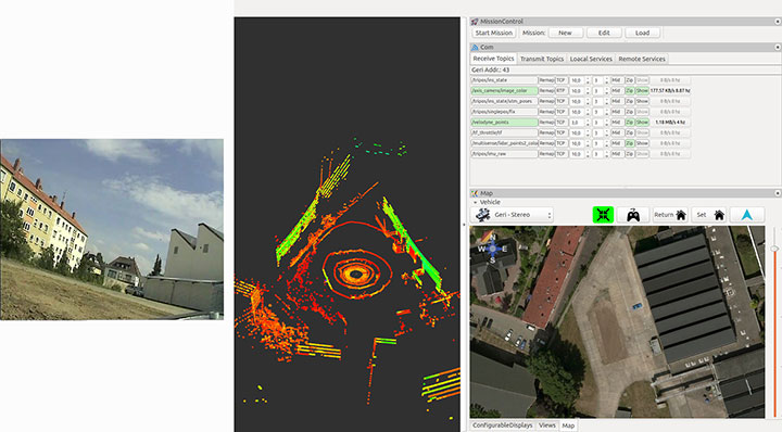
Figure 4 shows examples of the actual camera view from the UGV, and point cloulds and map generated by the UAV. The software layout can be customized by the user.
Figure 4. From left to right: the actual view by the PTZ camera onboard the UGV, the point cloud gathered by the UAV’s lidar, and the mission parameters and map of an aerial view.
POSITIONING OF UAV AND UGV
Automated operation of UGVs and UAVs requires valid position as well as attitude and heading information. In the case of using only one GNSS, signal quality and availability can be degraded by the environment (buildings) and can result in less precise or even a lack of position information.
GNSS Multi-Constellation. To overcome the risk of poor availability of GNSS-based position information, parallel usage of different GNSS can raise the number of received satellite signals: GPS, GLONASS, the evolving Galileo and BeiDou. When using a multi-constellation approach for positioning, one has to take care of several differing aspects between the GNSS. Each system uses a different geodetic reference frame and time basis. Measurements gathered from another GNSS system must be transformed into the reference frame of the desired system. The geometric distribution of the satellites is improved by using more than one GNSS constellation, indicated by a lower dilution-of-precision value.
The navigation software framework is designed for real-time computation and also for post-processing. In post-processing, the recorded sensor data is streamed to the software framework with the option of changing several parameters and settings for calculation. One option is to exclude satellites at low elevation from position calculation by changing the cut-off elevation for these satellites. This parameter will be changed to simulate environmental conditions that block receiving GNSS signals, like buildings within urban scenarios, to compare the availability of received GNSS signals for single- and multi-constellation-based position calculation.
Recorded data of a real-world test serves as the database for the post-processing with different cut-off elevation parameters. At the beginning of the field test, there was a short initialization period to boot the OS and to start basic processes for positioning. After that, a predefined mission was flown and the GNSS measurements have been saved for the described post-processing.
Post-processing has been performed with different cut-off elevation parameters of 5° up to 35°. In the case of 35°, the number of GPS satellites is reduced to the minimum for position calculation of four, in contrast to 5–7 available satellites for a multi-constellation based solution.
GNSS/IMU Fusion. Using the GNSS multi-constellation approach can increase availability of position information. For attitude and heading determination, an IMU is nevertheless indispensable. Additionally, the frequency of the pure GNSS-based positioning information is usually between 1 Hz to 5 Hz within the described hardware setup. Meaningful georeferencing of the environmental sensors requires much higher frequency position and attitude information.
The IMU provides high-frequency 3D measurements of accelerations and angular rates. Using common strapdown algorithm processing, high-frequency position, velocity, attitude and heading information is provided in real time. Due to the short time stability of pure inertial navigation, the GNSS positioning results are used for aiding purposes within the Kalman filter’s update step. To overcome the absence of GNSS aiding information even when using multi-constellations, there are mainly two options. First, a short coasting period is possible after the data fusion has reached a steady state.
Second, due to the highly modularly design of the navigation software framework, it is possible to use position or attitude increments from environmental sensor data processing for aiding the IMU.
The vehicle’s state vector is then distributed with high frequency within the system for georeferencing measurements of the environmental sensors, especially the RGB camera and the lidar for photogrammetry and simultaneous location and mapping (SLAM) applications.
PHOTOGRAMMETRY AND SLAM
In major fire scenarios, maps can be out of date. Therefore, techniques have been developed to gather a 2D overview based on several single RGB pictures taken and processed on board a UAV and transmitted to the ground station via data links. Additional processing of a 3D reconstruction of the scenario is an integrated feature within the ground station. Both approaches were implemented to get an automated rapid aerial mapping solution.
In the case of the 2D overview, SLAM algorithms, often used in robotic research, are adapted for this specific use case. These algorithms provide good results for a rapid aerial mapping solution to get an overview of the scenario, because the map is updated incrementally with every new image, but they are less precise, which can be compensated for by using the photogrammetric 3D reconstruction. The live mapping (SLAM) approach is based on the ORB-SLAM algorithm, and the photogrammetry-based approach uses commercially available photogrammetry software.
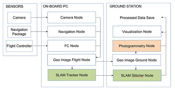
The systems, on the UAV for 2D and for 3D on the ground station, use the ROS framework for processing the visual sensor data and the described techniques for positioning, georeferencing and attitude determination. For data exchange between these frameworks, several software interfaces have been implemented. Figure 5 displays a flowchart of the implemented workflow.
The sensor/input data is received by corresponding nodes on the aerial vehicle. After adding the camera pose information to the image in the geo-image flight node, the image is sent to the geo-image ground node on the ground station. The SLAM process is separated into two parts. The SLAM tracker node calculates the transformation between images, and the SLAM stitcher node applies the transformations. The transformed images are displayed by the visualization node. The photogrammetry node receives the georeferenced images, stores the data, and initiates the photogrammetric processing once the survey is finished. The results can also be displayed by the visualization node and exported in a desired format.
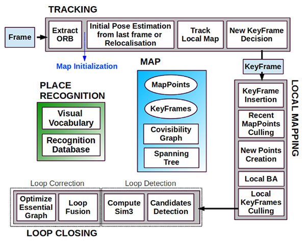
Visual SLAM. Computer vision-based algorithms have developed rapidly over the last few years. One method estimates a pose by using monocular image processing, known as parallel tracking and mapping (PTAM). This integrates a bundle adjustment and separates the tracking and the mapping procedure into different threads, leading to a real-time capable framework. These basic PTAM principles have been integrated into a robust loop-closing and another method of relocalization, known as Oriented FAST and Rotated BRIEF (ORB SLAM), shown in Figure 6. Here, tracking, local mapping and loop closing are separated into different threads (gray boxes), with the main map and place recognition in the middle.
Figure 6. ORB SLAM system overview [Mur-Artal, 2015].The tracking thread predicts the current pose from the last known position and movement by using a constant velocity model and performs a guided search of map points. If these points are found near the estimated position, the velocity model is valid and the tracking procedure continues. Otherwise, the tracking is lost and a relocalization in the global map starts by using a subset of features, which are increased after detection of corresponding features in other keyframes to optimize the camera pose and, finally, the tracking procedure continues. The last step of this procedure is to decide whether the current frame contains enough information to be inserted as a new keyframe for further calculations.
To mark a frame as a new keyframe, the frame must fulfill all of the following conditions:
More than minimum number of frames has passed.
Local mapping is on idle or condition 1 fulfilled.
A minimum number of 50 points is observed.
A maximum of 90% of the features is already observed by the other frames.
When a new keyframe is passed to the local mapping procedure and inserted as a node into a co-visibility graph structure, new correspondences are searched in the connected keyframes to triangulate new points. Based on the information accumulated during the tracking, a point culling keeps only high-quality points in the map as well as a culling of redundant keyframes.
Then a loop closing is performed. This is one of the main improvements compared to PTAM. If a loop is detected, the drift accumulated in the loop is computed, and both sides of the loop are aligned and visible points are fused. In a final step, a pose graph optimization is done to achieve global consistency.
This information of the 3D camera pose is used to generate a 2D orthophoto in real time while the vehicle is flying. To create a 2D orthophoto, a common reference frame is approximated, which is orthogonal to all camera measurements. The projection is performed by using a projection model based on a pinhole camera.
After the compensation and distortion, the whole image can be stitched to the current global map.
Photogrammetry. This approach uses off-the-shelf photogrammetric processing software. The processing is triggered automatically when the survey is completed and all images are transferred to the ground station via data link. For georeferencing of the images, the camera location and the inner camera geometry were written to the EXIF file of each image by the geo-image ground node (Figure 5). To ensure an acceptable compromise between orthophoto quality and the required processing time, an analysis regarding the impact of the most relevant processing parameters has been performed.
Figure 5. ROS node layout with SLAM (green) and photogrammetry workflow (red).
The photogrammetry process consists of four steps:
camera alignment (optimizing the homographic equation)
mesh creation by generated tie points
orthophoto creation (dense cloud or digital elevation model)
export.
Analyses and Evaluation. To evaluate the correct workflow of both approaches of 2D live-stitching and the 3D photogrammetry, a real-world flight test above agricultural cropland has been performed. The results of both approaches are shown in Figure 7 and Figure 8. Generally, agricultural cropland and its mean textured surface pose a challenge for mapping processes because of the limited number of trackable features.
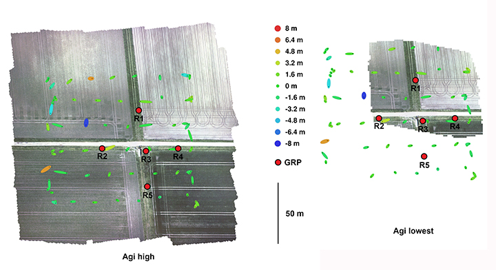
Figure 7. Orthophotos created with the profiles high and lowest (including ground reference points).Figure 8. Orthophotos created with 2D live stitching approach of cropland.
Four predefined profiles were used to cover the requirement of compromise between processing duration and quality of the generated orthophoto. Each profile level generates a corresponding level of alignment accuracy and mesh face count: lowest, low, medium and high.
To estimate the accuracy of the created maps by the different profiles, five ground reference points (GRPs) were distributed over the mission area. The location of the GRPs was determined using a RTK-GNSS system leading to a horizontal RMSE below 2 cm. To enable robust processing for this scenario, the overlap and the sidelap was chosen to be 70%. A ground-sampling distance (GSD) of 2 cm was needed to identify the GRPs. This resulted in a mission consisting of six times 100-meter (m) lines with a distance of 25 m in an altitude of 60 m over ground. During the flight time of 4.5 minutes, 271 images were taken.
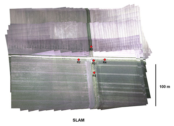
To compare the profiles, they were triggered one after another with the same set of images. The created results are shown in Figure 7. All profiles resulted in consistent solutions and were successfully georeferenced. The map based on the lowest profile could not recreate the complete area (Figure 7, right). The remaining profiles led to similar results without notable differences to visual inspection. The processing time varied between 1.2 and 3.6 minutes. A comparison of this and other criteria is given in Figure 9.
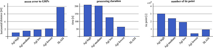
Figure 9. Evaluation and comparison of defined software profiles and visual SLAM.
The created final image of the SLAM pipeline is shown in Figure 8. The image was updated with every new image and was therefore finished before the UAV landed. The mean location error measured using the reference points was about 8 m, significantly larger than the errors observed in the photogrammetry results. In Figure 9 the results are contrasted to the results of the photogrammetry approach.
While the mean error in the low profile is half as high as in the lowest profile, the calculated errors using the medium and high profiles are not enhanced significantly. The number of tie points created by the lowest profile is an order a magnitude lower compared to the other three profiles.
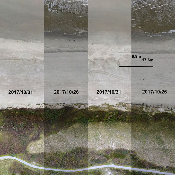
We conducted flight tests on Langeoog island in the North Sea, to gather information on efforts to protect the island’s coastline from water erosion. For this reason, sand was selectively washed up to the coastline by dredgers at the beginning of October 2017. Between Oct. 26 and 31, due to severe weather with a storm flood, a huge erosion of the washed up sand occurred, and the result is shown in Figure 10. The level of erosion was determined by comparison of the orthophoto of the same area. The dislocation averaged out to 9.9 m with some peaks up to 17.6 m.
Figure 10. Evaluation of erosion.
The 3D photogrammetry provides a more detailed image compared to the image of the 2D-live-stitching approach (Figure 11), but both approaches can provide the desired information of the area.
Figure 11. Result of the SLAM approach with camera poses and tracked features.
Both implemented approaches were successfully integrated to get the desired fully automated rapid aerial mapping solution. This also includes the basic tasks of the automated mission planning, camera control, image transport to ground station, automated processing and the visualization of the results.
CONCLUSION
The benefits of multi-constellation GNSS positioning have been demonstrated with a focus on UAVs and UGVs operating in catastrophic scenarios, especially where GNSS signal reception might be blocked. This position information is also used for georeferencing of images and visual reconstruction of the area. The overall system has demonstrated the capability of an automated orthophoto generation. Both implemented mapping methods — a 2D live stitching and a 3D photogrammetry — provided results that fulfill the requirements to get an instantaneous 2D overview and a contemporary 3D reconstruction of the area.
ACKNOWLEDGMENTS
This work was done within the joint research project ANKommEn, funded by the German Federal Ministry of Economic Affairs and Energy, administered by the Space Administration of the DLR (funding code: 50NA1518). Project partners are the Institute of Flight Guidance (IFF), the Institute of Mobile Machines and Commercial Vehicles (IMN) — both part of Technische Universität Braunschweig — and AirRobot GmbH & Co. KG, a German manufacturer of multirotor UAVs. The professional fire brigade of Braunschweig and the Lower Saxony Water Management, Coastal Defense and Nature Conservation Agency also participate as associated project partners.
SIMON BATZDORFER holds a Dipl.-Ing. in mechanical engineering and is a research engineer at the Technische Universitaet Braunschweig, Institute of Flight Guidance (IFF).
MARKUS BOBBE holds a M.Sc. in aerospace engineering and is a research engineer at the Braunschweig IFF.
MARTIN BECKER holds a Dipl.-Ing. in aerospace engineering and is a research engineer at the Braunschweig IFF.
ULF BESTMANN received his Dr.-Ing. in mechanical engineering from TU Braunschweig. He is head of the navigation department of the IFF. He co-founded the company messWERK GmbH, a service provider in flight testing and certification.
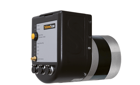
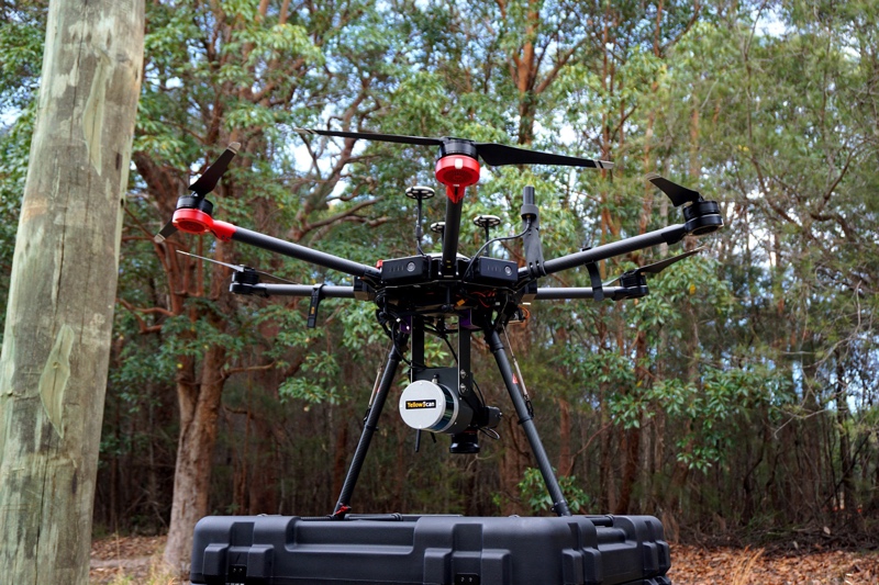
YellowScan has launched a new lidar system, the Surveyor Ultra. It integrates the Velodyne VLP-32C scanner and the Applanix APX-15 GNSS/inertial measurement unit (IMU).
With high density (600,000 shots per second), the system is suitable for high-speed UAVs and long-range needs (maximum range: 100 meters). Its light weight (1.7 kg) makes it easy to mount on any drone, including vertical takeoff and landing (VTOL) UAVs.
As for all YellowScan lidar systems, the Surveyor Ultra is a turn-key system fitted for under vegetation 3D modeling and fast data processing, the company said.
Applications such as forestry, archeology and environmental research will benefit from Surveyor Ultra, as they require long-endurance flights high above trees or over rocky mountains and rugged terrain.
“The Surveyor Ultra shows great potential to safely and efficiently operate lidar on lightweight fixed-wing UAVs,” said Tristan Allouis, YellowScan CTO. “The Surveyor Ultra completes our product line, including the successful Surveyor Lidar System (integration of the VLP-16 scanner from Velodyne).”
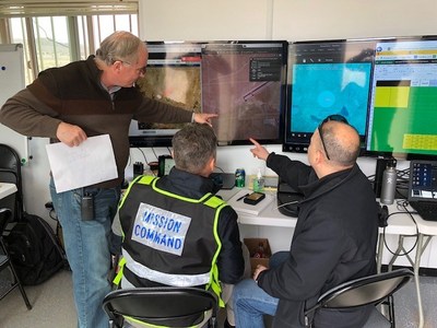
The Nevada Institute for Autonomous Systems (NIAS) and its NASA Unmanned Traffic Management (UTM) partners flew multiple unmanned aerial systems over a week-long testing period at the Nevada UAS Test Site at the Reno-Stead Airport.
NASA UTM Testing. Credit: NIAS. (PRNewsfoto/Nevada Institute for Autonomous)
This third phase of NASA’s UAS testing (TCL 3) again focused on airspace management technologies that will enable the safe integration of UAS into the national airspace.
NASA provided a Flight Information Management System (FIMS) research platform that will serve as a future prototype system for the U.S. Federal Aviation Administration (FAA) to use to coordinate with unmanned service suppliers operating throughout the nation.
Research areas of emphasis during the testing included UAS ground-control interfacing to locally manage operations, communication, navigation, surveillance, human factors, data exchange, network solutions and beyond-visual-line-of-sight (BVLOS) architecture.
On media day, a team from the Reno Fire Department simulated an incident with a victim experiencing severe blood loss and who needed an immediate transfusion. A multi-rotor UAS from Drone America was equipped with a container that held an actual packet of blood to be transported via drone in Nevada.
High winds and frigid temperatures tested both the drone and those on the ground, but the drone successfully landed in the designated landing area so that firefighters could retrieve the blood packet and begin the faux-transfusion.
The partners not only demonstrated drone flight capability, but also tested UAS traffic mapping and sensor and radar technology, all of which were connected through a NASA UAS Service Supplier (USS) network to NASA Ames.
Technology Capability Levels
NASA’s near-term goal is the development and demonstration of a possible future UTM system that could safely enable low-altitude airspace and UAS operations. Working alongside many committed government, industry and academic partners, NASA is leading the research, development and testing that is taking place in a series of activities called “Technology Capability Levels (TCL)”, each increasing in complexity.
UTM TCL1 concluded field testing in August 2015 and is undergoing additional testing at an FAA site. Technologies in this activity addressed operations for agriculture, firefighting and infrastructure monitoring, with a focus on geofencing, altitude “rules of the road” and scheduling of vehicle trajectories.
UTM TCL2, completed in October 2016, leveraged TCL1 results and focused on beyond visual line-of-sight operations in sparsely populated areas. Researchers tested technologies that allowed dynamic adjustments to availability of airspace and contingency management.
UTM TCL3, just completed, leveraged TCL2 results and focused on testing technologies that maintain safe spacing between cooperative (responsive) and non-cooperative (non-responsive) UAS over moderately populated areas.
UTM TCL4, with dates to be determined, will leverage TCL3 results and focus on UAS operations in higher density urban areas for tasks such as news gathering and package delivery. It will also test technologies that could be used to manage large-scale contingencies.
NASA’s UTM technologies research and development is taking place in collaboration with the FAA. Results of research in the form of airspace integration requirements are expected to be transferred from NASA to the FAA in 2019 for the FAA’s further testing.
“Advanced flight and highly technical scenarios like drone detection, surveillance of critical infrastructure aerial package delivery of critical first responder medical supplies, to the important NASA data interoperability protocols that will eventually form the backbone of the UTM system, we focused heavily on communications, navigation and surveillance to produce critical data for the NASA TCL 3 Campaign,” said Chris Walach, the senior director of NIAS and the FAA-designated Nevada UAS Test Site. “Our Nevada teammates did an amazing job working together to successfully complete the first series of major testing for NASA’s TCL 3 Campaign.”
Tony Murfin Contributing Editor, Professional OEM & UAV, GPS World
As the days tick down towards the always-anticipated Association for Unmanned Vehicle Systems International (AUVSI) Xponential convention in Denver May 1-3, the unmanned vehicle industry is preparing once more for one of its largest exhibitions.
More than 750 exhibitors will be spread over a huge 370,000-square-foot exhibit floor at the Colorado Convention Center and 8,500 visitors from unmanned systems and robotics are expected to come to share ideas, gain insights and carefully examine the unmanned innovations on show.
STEM Outreach. This year the show will not only feature industry innovation and growth, but will also highlight resources for potential science, technology, engineering and math (STEM) graduates with interactive and engaging content, including:
A buildathon/hackathon to conceive, design and build inventions during a timed competition prior to Xponential. Final projects will be displayed on the Xponential show floor as a representation of innovation and collaboration.
A dedicated area in the Xponential exhibit hall will describe the STEM education programs and services supported by AUVSI and the AUVSI Foundation to foster and cultivate the next generation of innovators and leaders.
An area of the show floor will also showcase the winners of student robotics competitions.
Denver area high school students will be invited to tour the exhibit area to introduce them to emerging unmanned technologies and applications.
A reception at the show promises to mix young professionals in unmanned systems with seasoned industry leaders, and finally,
The Women and Diversity in Robotics forum will feature speed networking with leaders to review STEM opportunities for career-focused women and girls.
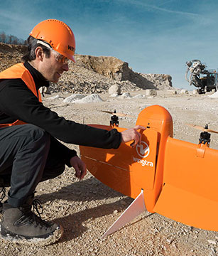
Survive and Thrive. Meanwhile, the Denver exhibition will demonstrate how the rapidly evolving world of UAVs has encouraged “survive and thrive” for those new entrants who together seem to have adapted to address almost any and all opportunities. We’ll mention a couple of examples here, and attempt to provide a better cross section of the huge number of companies and products present following the actual show.
For instance, one of the drawbacks for small, predominantly electric-powered, multi-rotor UAVs is that their endurance is limited. Providing longer duration operations may be outside their envelope — for such longer term things as providing temporary mobile-phone signal coverage, or police/agency reconnaissance/search, or for larger vertical inspection jobs.
Presumably, floating one of several available models of lighter-than-air, blimp-type UAVs might be more expensive or cumbersome than using a multi-rotor unmanned vehicle, so overcoming power-supply issues would seem to be key. One way to do this is to attach a strong tether bringing power up from the ground.
Orion UAS. The Elistair (France) Orion UAS will no doubt be featured on the company’s booth. This multi-rotor UAV has been developed for longer term aerial surveillance and telecommunications operations. Typical users include law enforcement, private and public safety, national security, asset protection, emergency communications and crisis management, so these tethered drones are deployed by police forces, public security departments, public and private security companies, and governments in more than 30 countries.
Photo: Elistair
The Orion UAS uses industrial components and system redundancy, including autopilot sensors, motors, power distribution and logic controls, and has an emergency parachute system. The patented micro-tether system ensures a stable platform supplied with continuous power from the ground to enable up to 10 hours of endurance. The mechanical structure of the drone is designed to sustain strong winds with maximum stability. With system redundancies and automated emergency procedures, the user is able to focus on safety-critical missions and data collection, while the risk of human mistakes is reduced.
The onboard camera has both FLIR and optical, enabling night/day surveillance with gimbal stabilization and low latency — the 30x optical zoom makes it possible to detect a moving person from kilometers away. And the tether system provides high-speed, interference-free data transmission so the system is also virtually undetectable. It’s easy to see why tethered drones are becoming more popular for security applications.
Identifying UAVs. At the FAA Unmanned Aircraft Systems (UAS) Symposium last week in Baltimore, a key issue discussed concerned remote identification and tracking of drones. It would seem that the FAA is about to announce a new rule that could eventually clear the way for drones flying over people and beyond line-of-sight of their operators — and this may be a key topic of discussion at Xponential.
The FAA rule appears to mandate that every drone should in some way communicate its identification — presumably its FAA registration ID — so that its operator could also be known.
One well-known company, Ford, has already announced that it has a concept using onboard collision lights on a drone to optically signal the 10-digit FAA registration number to the ground for capture and decoding. Maybe other exhibitors at the show will have other solutions — perhaps radio based? We’ll see.
Sensefly eBee drone.
Sensefly’s eBee. At the sensefly booth, we may also hear about several interesting announcements on recent drone applications:
Products on display will include the RTK/PPK-enabled eBee Plus professional mapping drone, the eBee SQ drone for agricultural applications and the albris mapping and inspection drone, as well as the senseFly S.O.D.A camera and GeoBase.
In addition, senseFly sales manager and GIS scientist Briton Voorhees will deliver a presentation titled, “Comparing workflow and point cloud outputs of the Trimble SX10 TLS and senseFly eBee Plus drone,” on Wednesday, May 2, at 11 a.m. in the Mapping and Surveying Track.
Booth visitors can also find out more about senseFly’s comprehensive 360 solutions, which are designed to improve operational efficiencies and support decision-making in the surveying, mining and quarries, agriculture and inspection sectors.
And many more. GNSS players also expected to be at the show include Hemisphere GNSS, NovAtel, Rockwell-Collins, Septentrio, Tersus, Trimble, Accord/Aspen Avionics, Comnav, Navtech, Swift and Topcon, as well as GNSS chip manufacturers u-blox and Intel — although Intel may likely focus on its UAV/communications offerings at this show.
There will also be a number of antenna suppliers, inertial sensor manufacturers, UAV autopilot manufacturers and several ancillary electronics and mechanical systems suppliers — all trying to solidify their positions in the UAV vehicle and systems integration supply chain.
The major focus, as usual, will be on UAV/UAS vehicle manufacturers and system integrators and their products — there is always a great exhibition of actual UAVs from all sectors of the industry.
So, along with a parallel program of educational presentations on a wide range of industry aspects, the AUVSI Xponential convention promises to have plenty of opportunities to find things of interest to almost anyone, and many areas to focus on for experts already in the industry.
Police say a video from the Uber self-driving car that struck and killed a woman on March 18 shows her moving in front of it suddenly, according to Bloomberg Technology.
Uber Technologies Inc. halted its autonomous vehicle tests after one of its cars struck and killed a woman in Tempe, Arizona, in the first pedestrian fatality involving the technology.
A backup driver was behind the wheel but not operating the vehicle. “The driver said it was like a flash, the person walked out in front of them,” Sylvia Moir, the police chief in Tempe, Arizona, told the San Francisco Chronicle. “His first alert to the collision was the sound of the collision.”
The Uber had a forward-facing video recorder, which showed the woman was walking a bike at about 10 p.m. and moved into traffic from a dark center median.
“It’s very clear it would have been difficult to avoid this collision in any kind of mode,” Moir said.
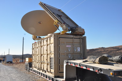
Forty-five unmanned aerial vehicles and drones fell out of the sky during a U.S. Army exercise after Raytheon’s advanced high-power microwave and laser dune buggy engaged and destroyed them.
These common threats were knocked down during a Maneuver Fires Integrated Experiment (MFIX), held in December at the Fires Center of Excellence at Fort Sill, Oklahoma.
The directed energy system emits an adjustable energy beam that renders drones unable to fly. (Photo: U.S. Army)
The directed energy system emits an adjustable energy beam that, when aimed at airborne targets such as drones, renders them unable to fly.
The MFIX event brought military and industry leaders together to demonstrate ways to bridge the Army’s capability gaps in long-range fires and maneuver short-range air defense.
Raytheon’s high-power microwave system engaged multiple UAV swarms, downing 33 drones, two and three at a time.
Raytheon’s high-energy laser, or HEL, system identified, tracked, engaged and killed 12 airborne, maneuvering Class I and II UAVs, and destroyed six stationary mortar projectiles.
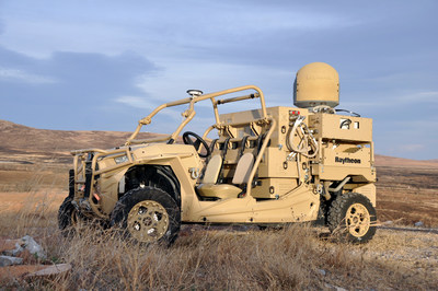
The vehicle-mounted laser is installed on an all-terrain Polaris militarized vehicle. (Photo: U.S. Army)
The vehicle-mounted laser combined a solid state laser with an advanced variant of the company’s Multi-Spectral Targeting System and installed them on a small, all-terrain Polaris militarized vehicle.
The system delivers 300 seconds of invisible, precise and instantaneous energy and five hours of intelligence, surveillance and reconnaissance from a single charge, Raytheon said.
Coupled with a generator, the HEL weapon system provides military members with counter-UAV capabilities and a virtually unlimited magazine.
“The speed and low cost per engagement of directed energy is revolutionary in protecting our troops against drones,” said Thomas Bussing, Raytheon Advanced Missile Systems vice president. “We have spent decades perfecting the high-power microwave system, which may soon give our military a significant advantage against this proliferating threat.”
Raytheon and the U.S. Air Force Research Laboratory worked together under a $2 million contract to test and demonstrate high-power microwave, counter-UAV capabilities.
“Our customer needed a solution, and they needed it fast,” said Ben Allison, director of Raytheon’s HEL product line. “So, we took what we’ve learned and combined it with combat-proven components to rapidly deliver a small, self-contained and easily deployed counter-UAV system.”
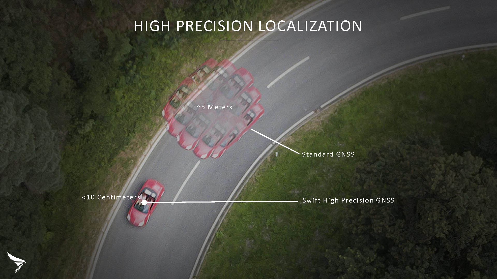
Swift Navigation has released Skylark, a cloud-based GNSS corrections service delivering centimeter-level accuracy without deploying and maintaining a GNSS network. Skylark targets autonomy applications at scale and enables high-precision positioning for mass market automotive and autonomous vehicle applications.
Skylark works with both of Swift’s multi-band, multi-constellation GNSS receivers, the Piksi Multi and the Duro ruggedized industrial receiver. Swift added GLONASS support in its 1.4 firmware upgrade, announced earlier this month, and aims to include Galileo and BeiDou in the near future.
Previously known as a hardware company, Swift Navigation appears to be shifting its focus a bit, including an Internet-delivered service in addition to its GNSS receivers. It has recently focused more closely on the automotive sector; it also has customers in drone technology, robotics and precision agriculture.
Its new platform for high-precision GNSS navigation of autonomous vehicles, via Internet connectivity, Skylark delivers fast convergence times measured in seconds, using positioning algorithms to provide a continuous stream of data to individual devices from the cloud. The data stream allows for quick and robust positioning and high reliability and availability, even in challenging environments, according to the company.
The Skylark service offers accuracy at the centimeter level. (Image: Swift Navigation)
Critical requirements for real-time absolute localization through GNSS for the automotive sector, according to Fergus Noble, co-founder and CTO of Swift Navigation, are:
high accuracy; centimeter level
availability; fast convergence, measured in seconds
integrity
scalability to support a large vehicle population
low cost.
Internet-Delivered via Cell Network
The last two requirements are fulfilled by the cloud-based approach. He characterized Skylark as a hybrid of RTK (Real Time Kinematics) and PPP (Precise Point Positioning) approaches augmented by Swift’s intellectual property, with corrections delivered over the Internet as provided by the cellular network, which he described as “robust to outages.” Cell coverage along road networks is good, Noble asserted, and 5G applications are increasing that coverage and will further enable connected vehicles. Automotive OEMs are comfortable with the level of cell coverage for this application, according to him. There has been testing to show robustness in most rural areas, and network operators are dedicated to increasing this.
“Skylark operates like a utility,” said Noble. “It is a simple, low-cost Internet data stream that provides customers with a complete high-integrity GNSS solution. Simply supply a Swift receiver with power and Internet connectivity and get real-time corrections for highly-dynamic GNSS applications.”
To realize the Skylark service, the company hired a team of cloud-based engineering experts who had a role in building Amazon and Oracle critical infrastructure. Swift Navigation is initially launching only with its own devices, but is making the service publicly-available for any customer in any vertical requiring precise positioning. “Every car company is building in autonomous functionality,” noted Noble, making clear who the company is ultimately targeting.
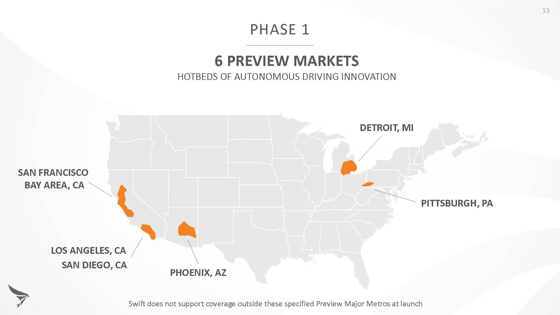
Skylark is currently offered in six metropolitan markets. (Image: Swift Navigation)
Swift has been working with beta customers for more than a year and is now previewing the service to all customers in six metropolitan markets: the San Francisco Bay Area, Los Angeles, San Diego, Phoenix, Pittsburgh and Detroit. The company envisions full contiguous U.S. and ultimately global expansion. Customers in preview areas with Swift receivers can sign up for Skylark and immediately start receiving corrections.
The service maintains low bandwidth to save on data costs and is offered with a free 30 day trial and flexible pricing plans. Skylark’s pricing structure includes a monthly plan and an annual plan. Enterprise pricing is available for volume orders.
Voyage Self-Driving Car Active Service and Coming Expansion
An early beta user of the service, Voyage deploys self-driving taxis in private communities across North America. “Skylark and Piksi Multi are working safely and efficiently in a real-world application today at The Villages, a retirement community in San Jose, California,” said Oliver Cameron, co-founder & CEO of Voyage.
Voyage incorporates Skylark GNSS corrections in controlled road networks in private communities. (Image: Swift Navigation)
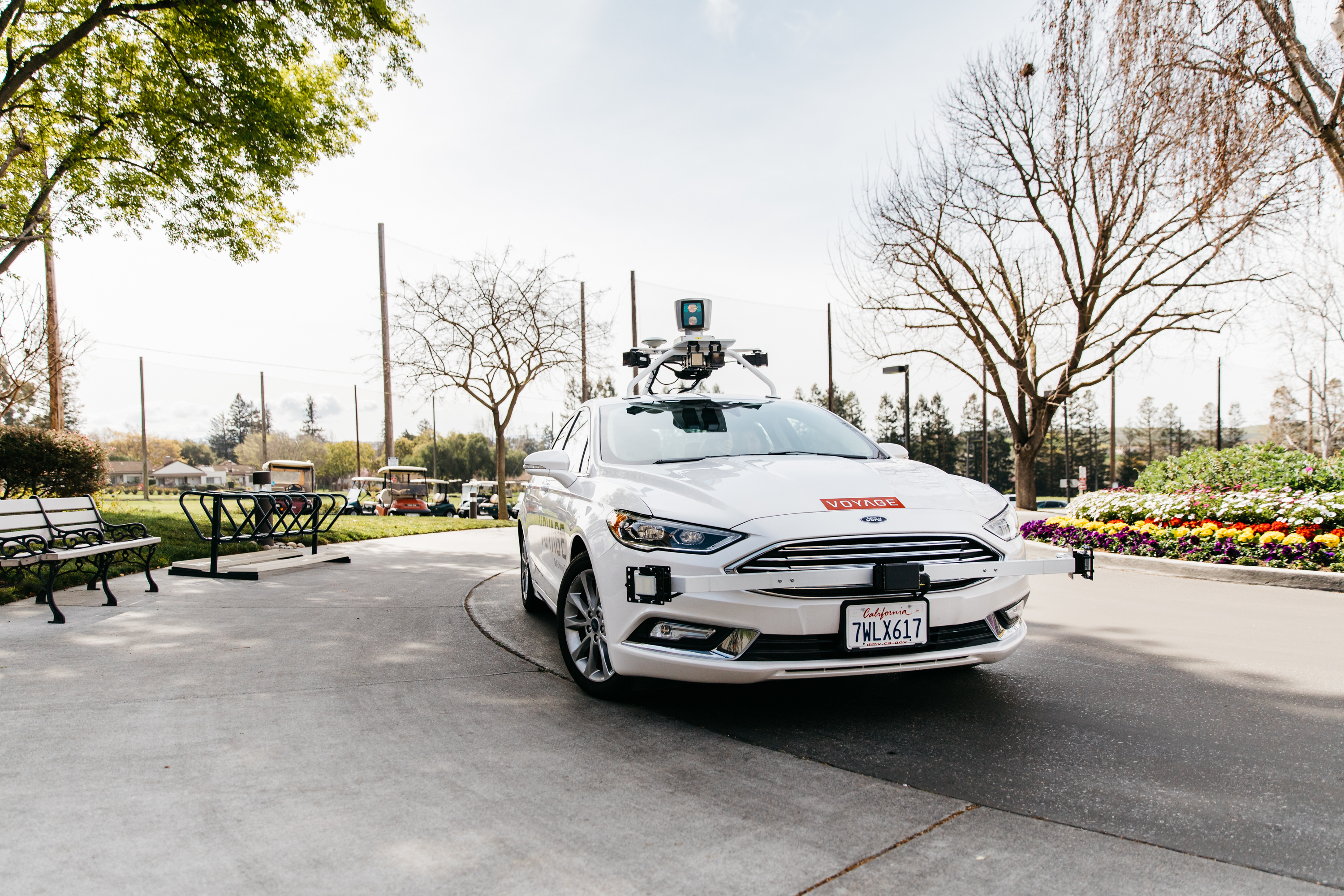
Voyage’s passenger cars carry a roof-racked suite of sensors: the Swift Navigation Piksi Multi GNSS receiver, LiDAR, cameras, radar, and an inertial measurement unit. A computer in the trunk integrates all sensor signals and uses the car’s CAN bus to operate steering, braking, and other functions. An operator sits behind the wheel at all times, sometimes with a co-pilot: one to watch the road ahead, and one to watch the software. “Safety is our first priority,” said Cameron.
The service is especially valuable to customers with mobility limitations that might prevent them from walking to an event or moving within the community. (Image: Swift Navigation)
The Voyage fleet stays within the bounds of a given community, where all roads have been precisely mapped, speed limits are lower and traffic patterns are more clearly defined than in metropolitan cities. The first in the San Jose area serves private community of more than 4,000 residents, with a 15-mile road network. Today, residents are able to summon a Voyage self-driving taxi using a smartphone app and have a ride waiting at their front door. This service is especially valuable to customers with mobility limitations that might prevent them from walking to an event or moving within the community. Voyage takes residents of The Villages to and from the gym, to visit with friends, to the golf course and to community center events.
Image: Swift Navigation
Voyage will next deploy the Swift product suite in its upcoming deployment launching to 160,000 retirees at The Villages complex in Florida, over a road network of 750 miles. It is currently in a “Q/A” testing phase on that site, working the technology and the local mapping through their paces.