A roundup of recent products in the GNSS and inertial positioning industry from the October 2022 issue of GPS World magazine.
OEM
Software
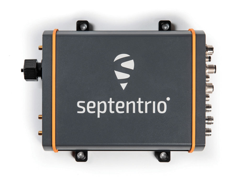
Aids GNSS/INS installation
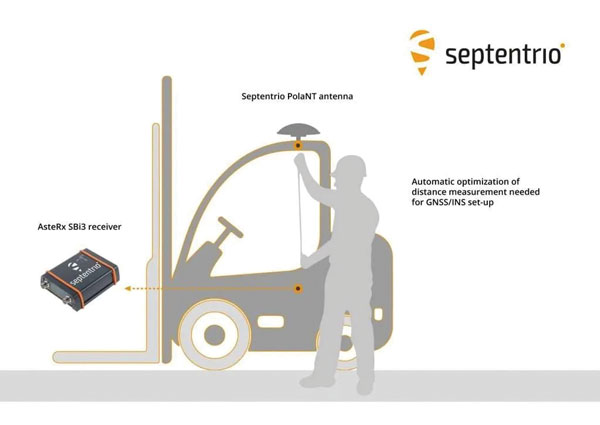
The RxLeverArm software tool aids integration of GNSS receivers that include inertial navigation systems (GNSS/INS). RxLeverArm is part of Septentrio’s RxTools software package included with every Septentrio GNSS/INS receiver. The new tool visualizes, validates and automatically calibrates the exact distance between the INS sensor and the antenna, removing the need for accurate distance measurements with complex instruments. For lever-arm compensation, users only need to measure the rough distance between the INS sensor and the main GNSS antenna reference points on the vehicle. Data is then logged under open-sky conditions, which allows the RxLeverArm tool to optimize the initial rough distance measurement and prevent common errors such as sign inversion.
Septentrio, septentrio.com
Testing Board
Enables proof of concept for IoT products and applications
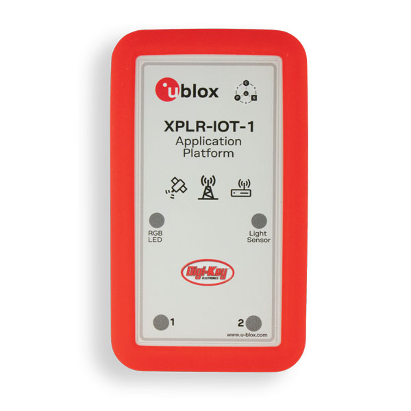
The u-blox XPLR-IOT-1 IoT explorer kit is an all-in-one package to test, evaluate and validate applications for the internet of things (IoT). The board hosts an ultra-low-power MAX-M10S positioning module capable of concurrently tracking four GNSS constellations, delivering highly reliable location data. Integrating relevant u-blox technologies and services into a capable prototyping platform with a vast selection of sensors and interfaces as well as cloud connectivity, XPLR-IOT-1 makes it easier to explore the potential of IoT applications.
u-blox, u-blox.com
GNSS Module
With RTK and dead reckoning
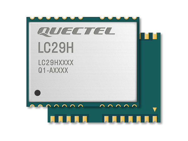
The LC29H is a dual-band multi-constellation GNSS module built using the Airoha AG3335 platform. It is available in multiple variants and optionally integrates real-time kinematic (RTK) and dead reckoning. The LC29H series offers high performance with power efficiency to meet the market needs of high-precision positioning at the centimeter and decimeter levels. The LC29H concurrently receives and processes signals from GPS, GLONASS, BeiDou, Galileo and QZSS. The modules are suited to an expanding market for autonomous lawn mowers, drones, precision agriculture, micro-mobility scooters and delivery robots.
Quectel Wireless Solutions, quectel.com
LoRa/GNSS Board
Equipped with u-blox tracking module
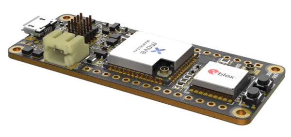
The Cicerone LoRa/GNSS board is a high-performance, low-power, Arduino MKR-compatible development board based on the u-blox MAX-M10S GNSS module and the MAMWLE LoRa module. It delivers high-performance GNSS, long-range wireless connection, and high-performance processing in a low-power solution for optimal battery life. The board allows users to build tracking applications worldwide with meter-level accuracy and to communicate long-range, low-power data via LoRaWAN. The integrated Li-Po charging circuit enables the Cicerone board to manage battery charging through the USB port. It has a compact 63 mm x 25 mm form factor and is compatible with all Arduino MKR shield boards. These boards all share a common pinout to enable developers to easily add expansions with minimal software changes.
Move-X, move-x.it
GNSS Module
New platforms improve positioning for wearables
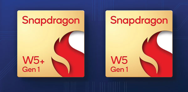
The Snapdragon W5 Gen 1 and W5+ Gen 1 platforms are designed to advance ultra-low power and breakthrough performance for next-generation connected wearables with a focus on extended battery life and premium user experiences. They incorporate innovations including low power islands for GNSS, Wi-Fi and audio; ultra-low power Bluetooth 5.3 architecture; and low power states such as Deep Sleep and Hibernate. New enhancements to the flagship Snapdragon W5+ platform offer 50% lower power, 2x higher performance, 2x richer features, and 30% smaller size, compared to the previous generation. The purpose-built platform is comprised of a 4 nm-based system-on-chip and 22 nm-based highly integrated always-on co-processor. By using these platforms, manufacturers can scale, differentiate and develop products faster in the continuously growing and segmenting wearables industry, Qualcomm said. Qualcomm also announced two reference designs from Compal and Pegatron, which showcase the capabilities of the platform and the company’s collaboration with ecosystem partners, helping customers develop products faster.
Qualcomm Technologies, qualcomm.com
SURVEYING
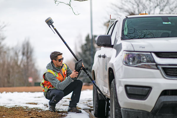
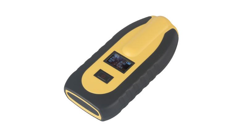
GNSS Receiver
Dual cameras enable vision RTK surveying
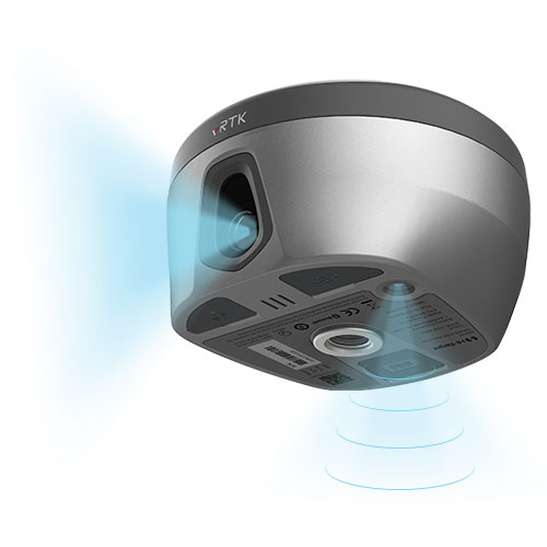
The pocket-sized vRTK GNSS real-time-kinematic (RTK) receiver is equipped with dual cameras to enable non-contact image surveying. It also has a nine-axis IMU module with auto installation for tilt surveying. Visual positioning technology combines imagery with high-precision positioning equipment, allowing users to obtain the location of the target from a distance. The Live View Stakeout function improves stakeout speed, while non-contact measurement greatly improves the usable range of GNSS. The vRTK receives 1,408 channels (GPS, GLONASS, BeiDou, Galileo, QZSS, IRNSS and SBAS). A new generation of GNSS engine supports the new frequency points B1C, B2a and B2b RTK decoding of BeiDou-3 satellites.
Hi-Target, en.hi-target.com.cn
Compact Receiver
Smart antenna for field work
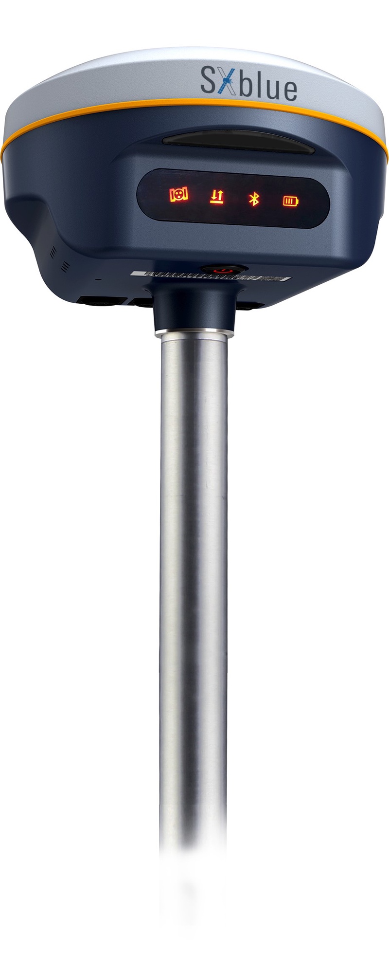
The SXblue SMART features an engine capable of tracking all-in-view GNSS signals, with interference mitigation and optimization for handling a wide frequency band. Weighing 850 g including battery, the SXblue SMART is compact and rugged. Its radio link is based on the Farlink protocol that allows a range of up to 8 km while reserving a wide bandwidth for transmission of real-time kinematic (RTK) data. In addition to a tilt sensor for measurements in hard-to-reach places, the SXblue SMART features a high-performance attitude measurement module that can detect and measure movement of the device. Also integrated are an inertial measurement unit and a thermometer for monitoring and controlling its internal temperature.
Geneq, geneq.com
Post-processing
For Windows and Mac users
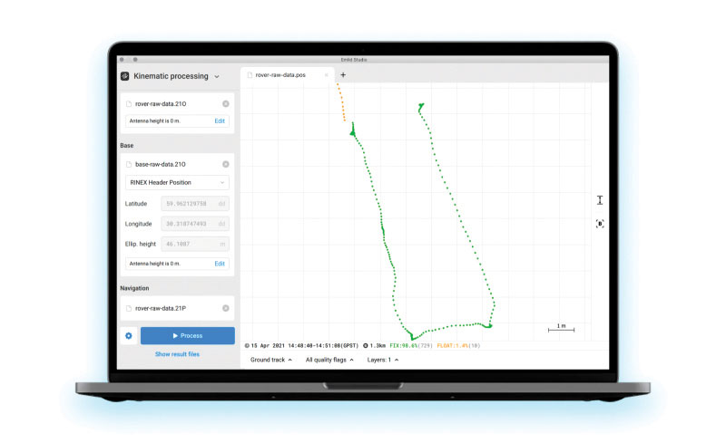
Emlid Studio is a new post-processed kinematic (PPK) application designed specifically for post-processing GNSS data. It allows users to convert raw GNSS logs into RINEX, post-process static and kinematic data, geotag images from drones (including DJI brand), and extract points from survey projects completed with Emlid’s ReachView 3 app. With Emlid Studio, users can post-process data recorded with Emlid Reach receivers and other GNSS receivers or NTRIP services. Post-processing requires RINEX observation and navigation files. Raw data in UBX and RTCM3 format also can be used through conversion.
Emlid, emlid.com
GNSS Receiver
Integrated receiver and antenna for portability
The P1 GNSS receiver has a high-precision module that tracks GPS, GLONASS, BDS, Galileo, QZSS and SBAS to deliver centimeter-level real-time kinematic (RTK) accuracy even in harsh environments. It is also equipped with an anti-jamming and anti-spoofing algorithm. The P1 GNSS receiver has integrated the GNSS module and GNSS antenna while keeping the device as small as a smartphone, which makes it portable enough to be worn around the neck or placed in a pocket. With 4G/Bluetooth communication, the P1 supports real-time positioning data transmission, providing users with a stable correction data steam and positioning data uploads. The P1 also can be mounted on a pole.
SingularXYZ, singularxyz.com
Smartphone App
Updates include vector map import
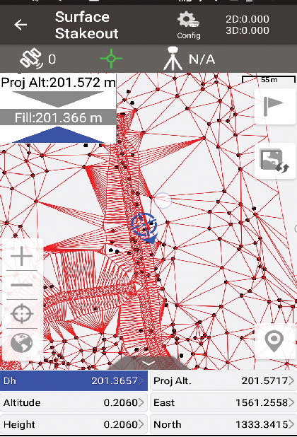
Nuwa surveying smartphone app version 2.3.3.2 has vector map import and digital surface stakeout. The Nuwa app runs on Android and is reliable and easy to operate. It has rich and powerful functions that can help surveyors complete measurements more efficiently and accurately. The app is designed to work with the David and Oscar GNSS receivers from Tersus GNSS, plus other receivers that support NMEA-0183. Features include the ability to configure base, rover and static surveys; graphical interface with background map (online/import); CAD stakeout, road stakeout and earthwork; data management (import/export multiple formats); and Bluetooth and USB connection support.
Tersus GNSS, tersus-gnss.com
Survey Application
Now supports Web Maps and multi-part geometries
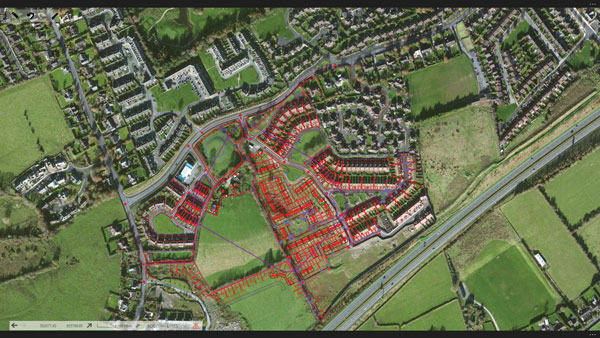
Version 3.2 of the survey application 1Edit allows the use of Web Maps (WMS) to be used as background layers, making it easier for surveyors to identify assets and changes in context. It provides easier configuration of background maps and supports hybrid working practices for surveyors. Where offline background maps are required, 1Edit supports multiple raster files and handles large image files, providing visual context for geospatial data when there is no data signal. Enhanced support for complex geometries increases efficiency as features with multiple parts share common attributes and IDs.
1Spatial, 1spatial.com
MAPPING
US Address Plug-In
Provides geocoding accuracy of 95%
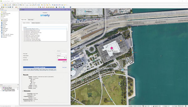
The Smarty U.S. Geocoding QGIS Plugin provides an easy way for users of the software platform to validate, standardize, and convert addresses to their latitude and longitude coordinates (geocodes). The plugin allows manual address entry as well as batch geocoding via CSV. It features a 95% match rate with the actual rooftop and parcel, as well as providing sub-address geocoding that can match secondary addresses such as apartment units and office-suite rooftops in building. The free plugin also includes supplemental metadata useful for many geographic information system (GIS) purposes.
Smarty, smarty.com
GIS Location Data
Datasets for the United States, UK, Canada, Australia and Europe

Maptitude 2022 is a major release of the geographic information system (GIS) and mapping software. It includes up-to-date, accurate data encompassing expenditure, geodemographic segments, gross domestic product, medical and banking locations, branded business locations, traffic counts, building footprints, address points and financial assets, as well as the tools to leverage this information to improve the location intelligence of organizations in markets such as healthcare, franchising, communications, logistics, retail, real estate and banking.
Maptitude, maptitude.com
Rugged Tablet
For mapping and data collection
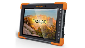
The Mesa Pro rugged tablet features 11th-generation Intel Core processors, a Windows 11 operating system, device customization options, a large sunlight-readable display and the “Juniper Rugged” company design. Standard Mesa Pro units come with an 11th Gen Intel Core i5 processor and 16 GB of LPDDR4x RAM. Core i7 and Celeron versions are also available. Each Mesa Pro configuration offers powerful performance and allows users to select the computing performance that fits their needs and budgets.
Juniper Systems, junipersys.com
AUTONOMOUS
Airspace Management
Data fusion across multiple data sources, including ADS-B
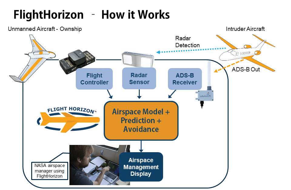
FlightHorizon COMMANDER is a situational awareness and safety system for UAV airspace management. The system provides airspace managers with either a 2D or 3D view of all aircraft in the selected airspace using a combination of sensors and data sources to create an airspace safety picture for pilots, airspace managers and command centers. The system is based on an exclusively licensed NASA patent and prototype that has been used in extensive flight testing. FlightHorizon COMMANDER functions as a visualization tool for airspace management, an active situational awareness tool, and a detect-and-avoid system that enables unmanned aircraft to avoid other aircraft and keeps drone pilots and airspace managers aware of the location and air traffic around their UAS and in their airspace.
Vigilant Aerospace, vigilantaerospace.com
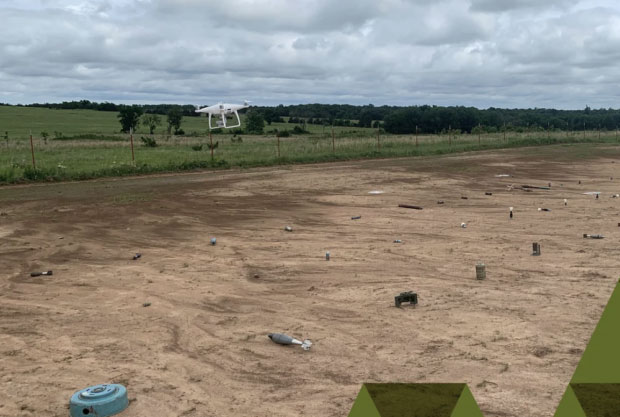
Heavy Lift Drone
Supports both automated and manual operations
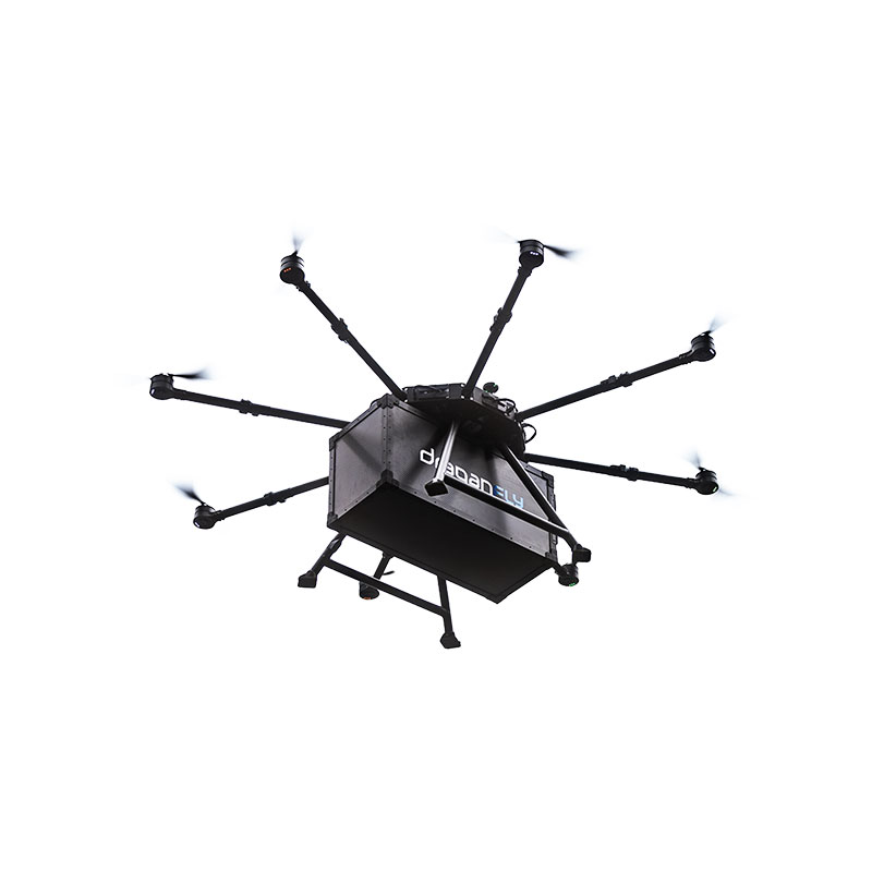
The Draganfly Heavy Lift Drone is a versatile, multi-rotor unmanned aerial vehicle designed to enhance deliveries and flight times. Compatible with a variety of interchangeable payloads, the heavy-duty drone can carry more and fly longer than the typical professional drone. It has a payload/cargo-lift capacity of 30 kg (67 lbs) and up to 55 minutes of flight time. The industrial UAV handles heavy winds and high elevations with ease. Its lifting capacity permits flexibility in carrying large high-end sensors such as hyperspectral and bathymetric lidar to conduct large-area surveys.
Draganfly, draganfly.com
Infrared Camera Module
Allows rapid MWIR integration for commercial, industrial and defense applications
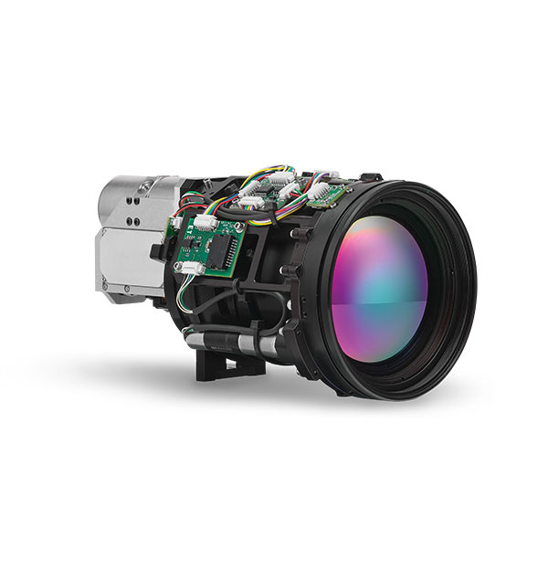
Part of the Neutrino IS series, the Neutrino LC CZ 15-300 is a new mid-wavelength infrared (MWIR) camera module with integrated continuous zoom lenses. Designed for integrated solutions requiring crisp, long-range MWIR imaging, the camera offers size, weight, power and cost (SWaP+C) benefits to original equipment manufacturers (OEMs) and system integrators for airborne, unmanned, C-UAS, security and targeting applications. The LC CZ 15-300 offers high performance, 640 x 512 high-definition MWIR imagery and 15 mm to 300 mm zoom capability for ruggedized products requiring long life, low power consumption and quiet, low-vibration operation. The camera module and lens are designed for each other, providing optimal performance.
Teledyne FLIR, flir.com
Nano Drone
Flies like a hummingbird
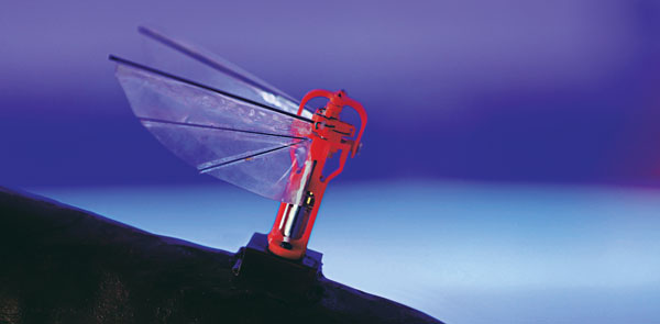
A miniature drone with flapping wings was demonstrated at the Teknofest Black Sea aviation and defense industry event, which took place Aug. 30 to Sept. 4 at the Samsun Çarşamba Airport. With its low detectability, the nano drone is being developed to perform reconnaissance and surveillance missions. It is still in research and development.
Aselsan, aselsan.com.tr
TRANSPORTATION
Lidar Transceiver
Enables machine vision at highway speeds
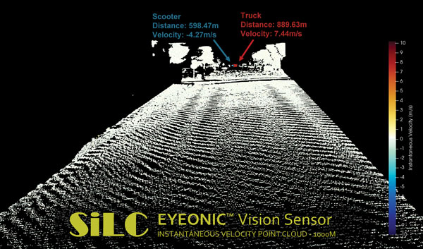
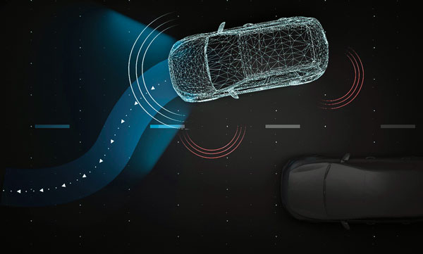
The Eyeonic Vision Sensor can perceive, identify and avoid objects at a range of more than 1 kilometer. The sensor is a frequency modulated continuous wave (FMCW) lidar transceiver that uses a silicon photonic chip. Long-range visibility is a requirement for autonomous vehicles, which require sufficient awareness to evade obstacles at highway speeds. This capability requires vision sensors to provide millimeter-level accuracy and depth at instantaneous velocity. The highly detailed and ultra-long-range information from the Eyeonic Vision Sensor enables robots to classify and predict their environments. The sensor is designed to be integrated into autonomous vehicles, security solutions and industrial robots.
SiLC Technologies, silc.com
Vehicle Computer
For fully connected buses, trucks and trains
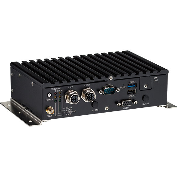
The nROK 1030 is a compact, rugged entry-level vehicle computer with an advanced GNSS receiver. The u-blox NEO-M9N module supports GPS, GLONASS, Galileo, BeiDou and QZSS signals. An Intel Atom x6211E dual-core processor 1.3 GHz/3 GHz (burst) is designed for harsh in-train environments. Its fanless, compact design is suitable for vehicles with limited space. The nROK 1030 has onboard CAN 2.0B for vehicle diagnostics and driver behavior management. WLAN Wi-Fi 6/6E/Wi-Fi 5 and WWAN 5G NR/LTE wireless data connectivity is optional. The nROK 1030 is flexible to meet the demands of various rolling-stock applications, such as wireless gateway, infotainment and digital radio data/voice transmission systems.
Nexcom, nexcom.com