We asked our Editorial Advisory Board (EAB) which emerging sectors are driving the most demand for advanced positioning and timing solutions right now?
“The defense sector needs an off-the-shelf GNSS module that is small, light and low power, yet also highly resilient — such as a military-grade location system — to satisfy the insatiable growth in drones. While this segment is about a tenth of the total commercial vehicle market, it is significant compared to the emerging autonomous driving segment, where the need for resilience is still trying to figure out the cost-benefit of mitigating intentional interference.”
“If I had to pick newly emergent sectors with the highest need for precise and continuous PNT, I would say the autonomous system operations sector and portion of the artificial intelligence (AI) sector. AI cannot provide spatially or temporally ‘intelligent’ support if it does not have access to precise positioning and timing information from outside itself. PNT sources do not depend on AI, but ‘autonomous’ AI must have reliable PNT.
“The primary driver is the broad adoption of autonomy and automation across industries such as construction, logistics, agriculture, infrastructure, defense, or even entertainment. Amplifying this demand is the proliferation of smaller and lighter UAVs, drones and robots. Where a single manned platform once required one navigation system, a drone swarm may require hundreds or thousands of units. It is the combination of these two forces, adopting autonomy and automation and multiplying platforms, that is driving demand growth.”
For many, the meaning of advanced positioning and timing solutions equates to solutions that provide higher accuracy and precision. For me, achieving an advanced PNT solution must require equal focus on the other PNT metrics — availability, integrity, continuity and coverage. Given the tumultuous state of the world these days, there is an emerging demand for solutions that enable resilient PNT in the defense sector, the commercial aviation and maritime sectors, in telecommunications and in power
A ceiling fan slowly churned, stirring the hot, humid air. Outside, warm rains pelted the muddy streets as distant langurs whooped in the thick jungle mists below.
An incessant fly caught the attention of the office’s lone occupant, hunched over a table covered with a large grid-lined sheet of paper. Pencils, erasers, French curves and straightedges lay scattered next to a stack of calculation sheets, but the man holding a pencil in one hand gripped a rolled newspaper in the other, intent on his battle with the fly.
Suddenly, the door burst open.
“Mr. Waugh!” the intruder exclaimed, panting as he rushed in.
“Radhanath,” Waugh replied in surprise, looking up from his maps. “I thought you were in Calcutta, 1,600 km away.”
“Yes, Mr. Waugh, I was, but this is too important to deliver by post.”
“Really, Radhanath. You intrigue me,” replied Waugh. “Come out with it. Your excitement is adding to this already unbearable heat.”
“Sir,” Radhanath tried to say calmly. “I have discovered the highest mountain in the world!”
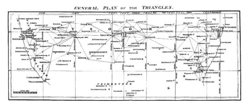
That conversation happened in 1852. It was the crown jewel of an effort that began 50 years earlier. Britain was on the ascent. Surveying was the mathematics of empire. India, Britain’s largest protectorate, had never been systematically mapped. The British East India Company needed to know what minerals, crops and commodities could be turned into profitable enterprises, where they were, and how to move them to ports. This depended on accurately mapping India. Infantry officer William Lambton proposed an audacious solution: measure the entire subcontinent with triangles.
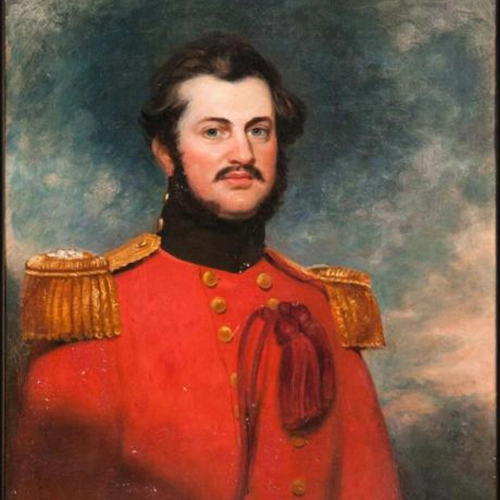
William Lambton
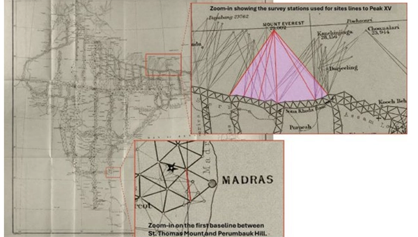
Lambton was granted the commission, and on April 10, 1802, the Great Trigonometrical Survey (GTS) of India began with a humble but critical baseline from St. Thomas Mount near Madras, 12 km south to Perumbauk Hill. Everything depended on the accuracy of this first baseline: even the smallest error would multiply as triangles spread across the subcontinent. Perfection was essential. The distance was measured with a 100-ft steel chain protected from the sun beneath A-frame tents to prevent thermal expansion. It moved slowly, 100 ft at a time from start to finish. Every link mattered. The baseline took 57 days.
To guarantee perfect alignment, Lambton relied on a massive custom-built theodolite. It weighed 1,102 lbs, requiring 12 men to carry. Surveyors planted stakes, stretched strings, and used the theodolite to correct for every change in elevation, turning a simple chain measurement into the geodetic foundation of the entire survey.
Time marched on faster than the survey. The East India Company estimated five years, but by 1818, the survey reached west to Mangalore and north to Hinganghat. It was too slow. Lambton’s vision of “an uninterrupted series of triangles…from sea to sea…to an unlimited extent in every other direction,” a complete geometric quilt covering India, proved implausible. Malaria took its toll. Lambton’s health declined and in 1823 he died at Hinganghat. George Everest inherited the survey.
The map of triangles covered Madras to Mangalore.George Everest
Everest recognized Lambton’s dream of total coverage would take centuries. Instead, he conceived a “gridiron” of chains running north–south and east–west, intersecting at right angles, scaffolding to which localized surveys could be tied. The shift is evident on the GTS map: dense triangulation in south-central India reflects Lambton’s ambition, while the more open, structural network elsewhere reveals Everest’s pragmatism.
By the 1830s, Everest’s survey party had grown into slow-moving caravans, reaching as many as 1,000 people at peak times. Contemporary accounts describe columns supported by elephants, horses and camels, with hundreds of porters carrying tents, instruments and provisions. The logistics were immense: scouts rode ahead to negotiate passage with villages, reapers with scythes gathered grass for the animals, hunters supplied fresh meat and a traveling treasury paid workers and suppliers. To villagers, an approaching column appeared like a military invasion. Negotiations for assistance and safe passage could halt the survey for days.
The survey’s path was relentless. The Great Arc bisected India along the 78th meridian, from Cape Comorin to Bangalore, across the Deccan Plateau, through Hyderabad, over the northern plains to Dehra Dun at the Himalayan foothills. They didn’t simply pass through. They stayed. Sometimes for weeks, building 50 ft masonry towers to mount the theodolites.
When daytime heat and haze made measurements impossible, Everest shifted to night surveying using powerful lanterns visible from 30 miles away. They constantly adapted due to temperature, atmospheric refraction, verification baselines measured at the chain ends. Every measurement propagated from that first line at Madras; a minor error would compound over thousands of miles.
The price was paid in lives. Malaria wiped out entire parties. Three officers died in the Terai, the malarial lowlands of northern India. Two more retired, health-shattered. Everest himself contracted malaria repeatedly, suffering partial paralysis. The climate, he wrote, was “very deadly.”
Andrew Waugh
The survey transformed the land. To achieve clear sight lines, villages were razed, sacred hills appropriated, and community supplies exhausted. Yet the work continued. In December 1841, almost 40 years since the GTS began, the 1,500-mile Great Arc was complete. The spine was in place. Everest retired in 1843, passing the work to Andrew Scott Waugh, who extended the gridiron eastward. Nepal and Tibet were closed to outsiders. Waugh understood the distant Himalayan peaks, more than a hundred miles away, would have to be measured from the border stations anchored to the GTS framework. Accuracy became even more critical. This shift in focus from Everest’s large sprawling triangles inching north like a spider’s web forming the Great Arc, to Waugh’s tight triangles hugging the Himalayan frontier is visible on the GTS map.
Over the next decade, Waugh’s teams pushed eastward through the jungles of Bengal, Bihar and Orissa, verifying baselines, fixing latitudes and longitudes astronomically, establishing stations that brought the peaks within mathematical reach. Along the entire border, surveyors recorded the peaks.
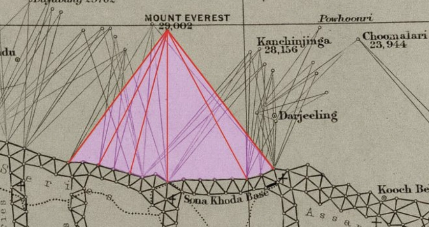
Close-up of the border survey stations used to observe Peak XV. (Credit: Royal Geographical Society)
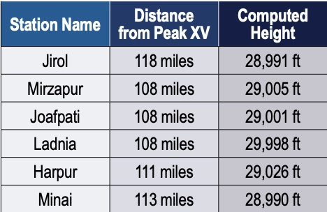
To measure Peak XV, six observation stations were selected across the Terai, the deadly malarial lowlands chosen for the clear site lines to the summit. From these stations, surveyors recorded azimuth and elevation angles across multiple seasons. They measured the summit at sunrise, when the peak was first illuminated. None of the surveyors knew the height of the mountains they were observing because distance could not be measured directly. Only when all stations were plotted on a map could the peak’s position be fixed and the elevation calculated. This high-level mathematics fell to the human computers in Calcutta, led by Radhanath Sikdar.
Radhanath Sikdar
By 1851, Sikdar had risen to chief computer, directing the department that transformed field observations into verified measurements. The 1851 Survey Manual acknowledged his distinction: “Babu Radhanath Sickdar, the distinguished head of the Computing Department…whose intimate acquaintance with the rigorous forms and mode of procedure…render his aid particularly valuable.” Yet, neither his education nor his geodetic calculation training prepared him for the complexities of the Himalaya problem. Nonetheless, he took the raw observations and calculated the mountains’ heights to determine which, if any, of the distant peaks was truly the highest point on Earth.
Sikdar calculated the height of each of the peaks. There were many. It was slow, meticulous work. Peak XV required more than standard calculation. Six observation stations produced six independent height measurements, each requiring corrections for atmospheric refraction (light bending through air layers of varying density and temperature), Earth’s curvature (the summit was more than 100 miles away), and plumb-line deviation (the Himalayas’ mass pulled survey instruments slightly toward the mountains).
Sikdar applied the Method of Least Squares, a statistical technique for extracting the most probable value from multiple observations. Each station’s measurement carried uncertainty; combining all six through rigorous mathematics yielded a more reliable result.
The calculation took months. When Sikdar finished, he was stunned: exactly 29,000 ft recalculated and received the same result. The precision seemed too perfect. Sikdar knew the stakes. This wasn’t just another mountain. His calculations were correct. Peak XV was the highest point in the world, Chomolungma, meaning the goddess mother of the Earth. Such a discovery demanded the honor of delivering the news in person.
In April 1852, Sikdar traveled 1,600 km from Calcutta to Dehra Dun. The journey took weeks. He carried the calculations in his satchel and the announcement in his mind.
When Sikdar burst into Waugh’s office with the news, Waugh worried that exactly 29,000 ft (8,830 m) would make surveyors appear to have simply rounded. 2 ft were added, a small fiction to preserve credibility. The official height for Peak XV became 29,002 ft.
Waugh spent four years verifying before the official announcement in March 1856. The mathematics were sound from the moment Sikdar burst into that office. Then, 20 years later, the 1875 Survey Manual erased Sikdar’s name entirely. The British press called it “robbery of the dead.”
Sikdar’s calculations have stood the test of time. The 1954 Survey of India measurement, 102 years later, yielded 29,028 ft, a minimal difference. In 1999, GPS technology placed a receiver on Everest’s summit for the first time: 29,035 ft. The 2015 earthquake prompted the most comprehensive measurement yet.
On May 22, 2019, at 3 a.m., Nepali surveyor Khimlal Gautam departed Everest’s South Col for the 10-hour climb carrying 90 lbs (41kg) of equipment. The pre-dawn timing avoided crowds: the weight included a Trimble R10 GNSS receiver and ground-penetrating radar to distinguish rock height from snow depth. Eight continuously operating reference stations (CORS) were positioned across Nepal to receive signals from GPS, GLONASS, Galileo and BeiDou. Chinese surveyors simultaneously measured from the north.
Gautam spent hours on the summit, collecting data while his body slowly consumed itself in the death zone. He lost a toe to frostbite. A team member nearly died from oxygen depletion. Gautam understood, “Mount Everest symbolizes something in Nepal, but it’s not only a Nepal asset, it’s a world asset.”
The map of the Great Trigonometrical Survey. (Credit: Survey of India, via David Rumsey Collection)
On Dec. 8, 2020, Nepal and China jointly announced their result, agreeing for the first time the height was 29,031.69 ft. Sikdar’s error across 168 years was 31.69 ft, an accuracy of 0.11%.
From that moment in Dehra Dun, Sikdar, dusty from the road, calculations in hand, certainty in his voice, we trace backward through 50 years of framework building to understand what made that measurement possible. Peak XV, hidden in plain view, seen for hundreds of miles, refusing to be known, was finally measured.
Once we have measured it, we want to believe we know it, but the Indian and Eurasian tectonic plates continue to collide, pushing the mountain up four millimeters per year. Earthquakes in the region change the topography. The geoid problem persists: What does “sea level” mean 440 miles from the coast in a gravitationally dense region? Modern surveyors still grapple with the fundamental question: What does “height” mean when measured against a theoretical reference surface?
The Great Trigonometric Survey proved that surveyors could measure what they couldn’t touch, calculate what they couldn’t reach, and verify what they couldn’t see. It required building the geodetic infrastructure across a subcontinent, maintaining mathematical precision across decades, and accepting brutal human costs.
Then, the computer was a man. The information was in his satchel. The message was delivered in person. It was the first time the height of the highest known point was determined not by a physical barometer on a summit, but by mathematics alone, a man solving equations in a room 440 miles away. Sikdar proved the impossible: What couldn’t be touched could be measured, what couldn’t be reached could be calculated, and a man dusty from the road could hold the height of the world in the palm of his hand.
Four names for one mountain. Each represents a different understanding. Its ancient name, Chomolungma, and Sagarmatha, its national identity. Peak XV, its cartographic name marking the audacious attempt to measure it, and the name Mount Everest, the crowning achievement, a proclamation honoring mathematics, from Hipparchus who is credited with developing trigonometry to the computers, like Sikdar. It stands as a monument to all the surveying and cartography, especially of the 19th century accomplishing the impossible against extraordinary odds.
Surveying and mapping are jobs of courage and determination exploring the unknown, risking death in malaria-infested jungles, Everest working while stricken with partial paralysis, Abdul Hamid crossing a forbidden border, and Gautam’s predawn climb. They all understood what mattered was worth the risk. It is the surveyor’s call to arms: measure the Earth.
GNSS simulation has evolved well beyond accuracy testing. It now covers full-spectrum NavWar and PNT validation. Today’s simulators are expected to generate real-time GNSS, LEO signals, inertial measurement units (IMU), alternative navigation sources, jamming and spoofing — all from a single system.
“The number of signals continues to grow with the rise of multi-PNT sources and advanced threat capabilities,” said Jaemin Powell, senior product manager, NavWar & Simulation at Safran Federal Systems. “Our customers are preparing for GPS-denied operations, validating NavWar responses and ensuring resiliency in contested domains.”
Powell noted that Safran Federal developed BroadSim Genesis to enable simultaneous streaming of L1, L2, L5 and L6 GNSS and LEO signals with integrated jamming and spoofing — all within a compact 4U platform.
The company’s strategy is built on a software-defined architecture, allowing for rapid adoption to evolving threats and mission requirements, Powell said. Safran Federal collaborates closely with government stakeholders and defense primes to stay up-to-date with new requirements and incorporate real-world threat vectors, such as spoofing and jamming. The BroadSim platform supports software upgrades for every feature, from adding constellations and LEO signals to enabling hardware-in-the-loop (HIL) support or integrating additional PNT resources.
While defense and aerospace continue to serve as core markets, rising demand also is coming from space companies, LEO-PNT developers, and advanced electronic warfare laboratories now relying on Safran simulators.
“These users value the scalability, fidelity and flexibility of our simulation solutions, especially in environments with high dynamics,” Powell said. “They are looking beyond traditional GNSS, and we address that need with a simplified, all-in-one platform.
Large-Scale Simulation
“Large-scale simulation is technically demanding,” Powell added. “Generating thousands of signals across multiple bands with ultra-low latency and 1000 Hz update rates pushes both hardware and software boundaries.”
Maintaining the intuitive Skydel interface while adapting to evolving NavWar requirements remains a top priority for the company. For example, Safran Federal introduced real-time automated calibration for BroadSim Wavefront, which executes before every scenario. This allows users to power up and immediately begin testing, eliminating recalibration and setup delays.
“Simulation is more than just signal generation. It is about enabling operational confidence,” Powell said.
“Our platform gives users the ability to stress test systems, visualize behavior in real time and adapt quickly without relying on range time or live sky testing…We are enabling teams to meet their toughest NavWar and PNT challenges with confidence and flexibility. If you have demanding requirements, we are ready to deliver a solution that is intuitive, capable and built for the future.”
In universities across the world, theory lays the foundation, but in the field, realism builds true expertise.
For students studying GNSS engineering, textbooks and simulations alone are no longer enough. Tomorrow’s engineers need to use the same applications and work with the same complex environments that professionals face in the real world. This means using tools that generate actual RF signals, not just software abstractions — tools that recreate urban canyons, interference, jamming, spoofing and satellite dynamics with precision.
Safran has established the Minerva Academic Partnership Program, an initiative that brings its Skydel GNSS Simulation Engine to qualified educational institutions worldwide.
A Modern, Software-Defined Approach to GNSS Simulation
At the heart of this initiative is the Skydel simulation engine, a software-defined GNSS simulator. Built to leverage commercially available off-the-shelf (COTS) hardware, Skydel eliminates the need for proprietary hardware. It delivers the full spectrum of satellite constellations — as well as LEO ones — and frequency bands. By integrating Skydel in their projects, researchers now have the tools to pursue ambitious ideas with confidence, such as:
■ Designing and testing custom signals or constellations not yet in existence
■ Simulating real-world scenarios that can include both environmental and man-made interference
■ Integrating and testing additional sensors and platforms through open-source plug-ins and hardware-in-the-loop setups
■ Conducting rigorous resiliency testing against jamming and spoofing in a controlled, repeatable environment without real-world risk
■ Building their own simulator with existing hardware components around Skydel
Empowering the Next Generation of PNT Innovators
Through the Minerva program, Safran provides full-feature Skydel licenses for faculty and student use, creating an environment where learning and innovation thrive. This initiative not only eliminates the barrier to entry but also fosters collaboration between academia and industry –— fueling a new wave of GNSS advancements.
A Global Initiative
Today, Minerva includes more than 80 member institutions and boasts a growing portfolio of peer-reviewed publications and conference presentations.
“This momentum highlights the real-world impact of the program and its role in driving local research excellence and fostering a vibrant, collaborative international GNSS community,” said Pierre-Marie Leveel, program director of PNT simulation at Safran Electronics & Defense. “Safran Electronics & Defense’s Minerva program is more than just a software — it’s a mission to democratize GNSS simulation and nurture the next generation of PNT researchers. As innovation becomes more critical to national sovereignty, transportation, and space exploration, empowering students and researchers has never been more vital.”
Elevating GNSS Simulation
The evolution of Safran Electronics & Defense’s GNSS simulators — across both software and hardware — has been shaped by the growing demands of users and the broader market.
“The demand for multi-vehicle and multi-antenna scenarios has never been higher, and the same can be said for interference simulation,” said Pierre-Marie Le Veel, program director of PNT Simulation at Safran Electronics & Defense.
To address these challenges, Safran’s GSG-7 and GSG-8 Gen2 simulators are engineered to handle a range of applications, from basic to advanced GNSS jamming and spoofing resiliency testing.
The GSG-7 simulator is designed for location-aware applications and systems that depend on navigation or timing. With high-end performance — featuring a 1,000 Hz simulation iteration rate, high dynamics, real-time synchronization, and all-in-view satellite signal simulation — the GSG-7 is well-suited for development and integration projects that demand high performance and extensive constellation licensing. It supports multi-constellation and multi-frequency GNSS simulations and can be configured to operate with all current and upcoming GNSS signals.
Meanwhile, the GSG-8 Gen2 is the latest iteration of Safran’s GSG-8 model, offering flexible simulation capabilities for any device that relies on GNSS signals. Built on Safran’s Skydel-based simulation platform, the GSG-8 Gen2 helps users model scenarios.
Powered by high-end GPUs, the GSG-8 Gen2 offers reliable and precise GNSS signal testing. It can simulate thousands of signals, run multiple instances at once, and introduce jamming and spoofing to evaluate system resilience. The turnkey system features a redesigned chassis for greater connectivity, including six front-facing, high-quality RF outputs, a combined output covering the full GNSS bandwidth, and the same high-end simulation iteration rate as the GSG-7. This allows users to quickly get up and running with complex simulation requirements.
“The market is also demanding realism,” Le Veel said.
All Safran simulators are powered by the Skydel Simulation Engine, which is updated quarterly. Each release introduces new features, signals, and enhancements, enabling more authentic simulations and offering the flexibility to create virtually any GNSS testing scenario.
Staying Ahead of Market Changes and Signal Threats
The recent increase in signal interference threats has driven the demand for enhanced positioning, navigation and timing (PNT) resilience, leading to the broader use of both conducted and over-the-air (OTA) testing. The anticipated deregulation of controlled reception pattern antenna (CRPA) technology also is expected to open the door for civilian markets to perform testing.
“Throughout the past few years, Safran Electronics & Defense has massively revamped our approach to the Wavefront platform and now offers the GSG-Wavefront for those testing CRPA antennas against jamming and spoofing threats,” Veel said.
The ability to safeguard GNSS networks from jamming and spoofing attacks has never been more vital. Achieving this level of resilience calls for a GNSS simulator that can generate dedicated RF signals for evaluating the effectiveness of CRPA architectures.
Safran’s GSG-Wavefront, featuring a shared local oscillator (LO) design, stands out as a field-proven, off-the-shelf solution for CRPA receiver testing. It has a customizable platform that offers upgradable options powered by Skydel — the company’s GNSS simulation engine.
Le Veel added, “We are working hard to keep up with demand in both the defense and civilian markets.”
In addition, Le Veel noted that Safran’s GSG-Anechoic is attracting attention from users who work with anechoic chambers, thanks to its multiple, independent RF outputs, automatic antenna mapping, and built-in calibration features for delay and power loss.
Safran Electronics & Defense supports a wide array of users in both the civilian and defense sectors, spanning aerospace, critical infrastructure and transportation. In recent years, however, the company has seen its fastest growth in the New Space market. Safran’s simulators are used in a range of cutting-edge applications, including satellite navigation, low-Earth orbit (LEO) constellations, and rocket launch and landing systems.
“We are proud that the flexible tools and features we have included in Skydel are being used in these incredibly robust applications,” La Veel said.
A challenge for most GNSS simulation suppliers is ensuring compatibility and coherence with a wide range of GNSS receivers. La Veel shared that Safran Electronics & Defense is in a unique position, as it also designs and manufactures its own receivers, such as the newly released Skylight.
“Additional challenges can arise when developing new signals or constellations, such as the newest LEO ones, said La Veel. “Our close partnerships with both Xona Space Systems and TrustPoint have allowed us to overcome these challenges.”
A single GSG-8 Gen2 simulator from Safran Electronics & Defense can generate more than 2,000 signals without the need for additional hardware. This capability is essential when modeling legacy signals, multipath effects, jamming and spoofing scenarios, or even LEO-constellations.
Safran simulators support all legacy signals, including GPS, Galileo, BeiDou, GLONASS, NavIC, QZSS and SBAS, across all bands and security features such as M-code, PRS and Galileo OSNMA. The systems also offer compatibility with emerging LEO constellations, including Xona’s PULSAR X1 and X5, as well as TrustPoint. Custom Signals and Custom Constellation features offer users the flexibility to create entirely new signals and satellite constellations, or to modify existing configurations.
“It is de rigueur these days for companies to claim or incorporate AI into their solutions. In addition to using AI for tropospheric modeling based on real-world data, Safran Electronics & Defense has also taken a different approach to using AI in GNSS simulation,” Le Veel said.
He added that the company’s upcoming demonstration at ION GNSS+ 2025 will reveal Skydel AI, a new tool designed to make scenario creation and parameter setting as simple as writing an email. “The amount of people who can easily now test their prototypes, products or systems will dramatically increase as the steep curve to learn GNSS simulation is flattened.”
Markus Irsigler, Sebastian Kehl-Waas, Carsten Stöber, Jürgen Dampf, Rohde & Schwarz GmbH & Co. KG
GNSS jamming and spoofing pose a significant threat to global security, as satellite-based navigation and timing systems are utilized in various application fields, including critical infrastructure, transportation, military operations and communication networks. These intentional interferences disrupt signals or deceive GNSS receivers, leading to navigation errors, loss of situational awareness and potential safety hazards.
Local, low-power jamming is often used to deliberately prevent GNSS-capable devices from recording their positions and being tracked. Such jamming devices, known as personal privacy devices (PPDs), are typically used to prevent fleet monitoring, concealing personal travel, or evading toll systems. Although mostly illegal, PPDs are fairly widespread and can pose a significant threat to GNSS availability, at least on a local scale.
On the other hand, larger-scale incidents are observed very frequently. Regional jamming often occurs in conflict zones to protect military assets or disrupt enemy operations. Jamming has also been reported near critical infrastructure. Spoofing is typically less frequent than jamming, but it poses a more concerning integrity threat when incorrect PVT data is used for navigation. Well-documented events include the (in)famous 2017 incident affecting ships in the Black Sea, where a spoofed GNSS signal led vessels to report incorrect positions. Jamming and spoofing also play an important role in the Ukraine conflict, where it is used to disrupt enemy drones, guided munitions, and navigation. Such events clearly highlight the vulnerability of GNSS-dependent systems and the need for robust mitigation techniques and strategies.
Against this background, testing how GNSS devices react to such threats has become more and more important, especially if they feature dedicated jamming detection and mitigation techniques. In such cases, the main test objective is to verify that these detection and mitigation techniques work as expected and that the GNSS receiver reacts properly and as expected in response to such attacks.
Categorization of GNSS Threats
Although jamming and spoofing can be considered the most critical threats, GNSS signals can be degraded in various other ways. Signal degradation effects can occur anywhere along the path from the GNSS satellite to the user. They can be caused by the transmitting satellite itself, usually in the form of hardware malfunctions, typically referred to as “evil waveforms.” They can also occur along the signal path in the form of ionospheric and tropospheric errors or scintillation effects, or they can be a result of the conditions in the vicinity of the GNSS user. This includes jamming, spoofing, RF interference caused by other signals, as well as signal obscuration and multipath caused by buildings or trees.
“Evil waveforms” can pose a significant threat to GNSS signal integrity, leading to large positioning errors. However, the occurrence of this effect is very rare and therefore not specifically considered in this article. There are also some atmospheric effects that have the potential to significantly degrade the quality of GNSS signals. Especially ionospheric and tropospheric scintillation due to temporal, fast-changing atmospheric conditions can cause rapid amplitude and phase variations, leading to reduced C/N0 or even loss of lock. Again, this does usually not happen every day and is therefore not discussed in detail below either.
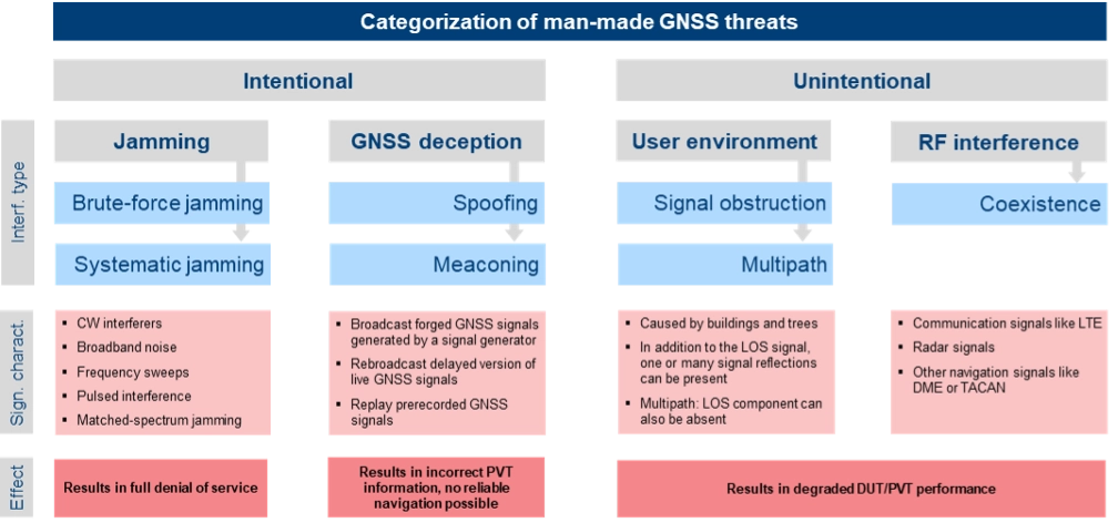
The most critical and common GNSS threats originate from interference signals that occur in the vicinity of a user receiver. Unlike system-inherent threats that originate from GNSS satellites or atmospheric conditions, these threats can be termed as “man-made” and categorized as shown in Figure 1.
Figure 1. Categorization of man-made GNSS threats. Credit: All figures provided by authors.
Jamming can be divided into two types of attacks. Brute-force jamming aims at completely blocking GNSS reception for a receiver by deliberately emitting interference signals like CW interferers, broadband noise or frequency sweeps with very high-power levels. As a result, the carrier-to-noise values will drop below the receiver’s acquisition and/or tracking threshold, and GNSS signals cannot be processed anymore. In contrast to such a simple jamming attack, where the attacker needs to have only basic knowledge about the GNSS signals (e.g. center frequencies and signal bandwidths), systematic jamming is a much more sophisticated attack, which can be further divided into
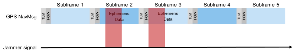
• Intelligent or smart jamming. The objective is to jam only a specific part of the navigation message (e.g. the ephemeris data section), so that the navigation message can never be fully decoded and the receiver will never be able to perform a position fix. All other parts of the navigation message remain unaffected, allowing signal tracking to continue for the receiver. Figure 2 illustrates this attack on the GPS L1 C/A signal.
Figure 2. An intelligent jamming attack performed on a GPS L1 C/A signal.
Smart jamming is much more complicated to implement for an attacker as the jammer must only be active during specific time intervals; this requires that the jammer is somehow synchronized with GNSS/Coordinated Universal Time. Moreover, the attack requires knowledge of the navigation message structure and what information the receiver needs to compute a position. Nevertheless, if done correctly, the attack is rather difficult to detect [1].
• Matched spectrum jamming. The objective is to generate a GNSS-like jammer signal with the same spectral characteristics as the real GNSS signals but without any valuable navigation information (i.e. the navigation message is missing). Matched-spectrum jamming is not straightforward, and to be effective, an attacker must replicate the GNSS signals for multiple visible satellites simultaneously, considering signal characteristics such as pseudo-random noise codes and, ideally, their correct Doppler shifts. In contrast to jamming, GNSS deception techniques aim to force the receiver to compute an incorrect PVT solution, compromising the integrity of GNSS-based navigation. The two basic methods are:
• Meaconing. This rather simple approach is based on rebroadcasting a delayed version of live GNSS signals. This can be realized by using a commercial GNSS repeater. Alternatively, previously recorded actual GNSS signals can be replayed.
• Spoofing. This includes generation and broadcast of forged GNSS signals. This is typically done using a GNSS simulator, but specialized, modified GNSS receivers combined with a transmitting unit can also be used. The simulated signals need to be self-consistent, i.e. a GNSS receiver must be able to compute a PVT solution based on the simulated constellation. Spoofing attacks can be rather simple, e.g. broadcasting high power signals that represent a different location than those of the receiver under attack. The aim is to force the receiver into a reacquisition process, tracking and processing only the fake GNSS signals. More sophisticated spoofing attacks are possible [2], but not discussed in this article.
Additionally, the PVT performance of a GNSS receiver can also be degraded by objects in the vicinity of a GNSS user, causing signal obstruction and reflections from buildings, trees, or the ground. Multipath can cause significant ranging and positioning errors. Multipath effects can hardly be avoided and must be seen as a permanent threat to GNSS signal quality.
Finally, other existing signals and services can interfere with GNSS, either because there is a frequency overlap (in-band interference) or harmonics from other signals fall into the GNSS bands (out-of-band interference). As an example, the upper part of the DME/TACAN band overlaps with a significant portion the GNSS L5 band. The effect of this type of interference on GNSS receiver performance can be analyzed by performing coexistence tests.
RX-Internal Detection and Mitigation Methods
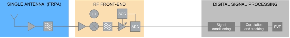
At least some of the threats discussed above can be detected and/or mitigated by the GNSS receiver. The capability of a GNSS receiver to detect and apply countermeasures to threats such as multipath, jamming or spoofing depends on the receiver’s availability of specific features and its basic architecture. Figure 3 shows the basic building blocks of a typical GNSS receiver with a single, fixed reception pattern antenna (FRPA).
Figure 3. Basic architecture of a FRPA receiver
The three basic building blocks are the antenna, the RF front-end and the digital signal processing section. The antenna is responsible for receiving the weak GNSS signals as well as for successive amplifying and band-limiting. It typically features a low noise amplifier (LNA) and a band-pass filter. The signals are then fed to the receiver front-end where the signals are amplified, down-converted to an intermediate frequency and converted to the digital domain. Part of this process is the automatic gain control (AGC) loop; the AGC acts as a variable amplifier, adjusting the power of the incoming signal and keep it constant over time. The sampled and quantized stream of IQ data is then fed to the digital signal processing section, where signal conditioning, acquisition and tracking, and PVT solution computations take place.
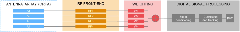
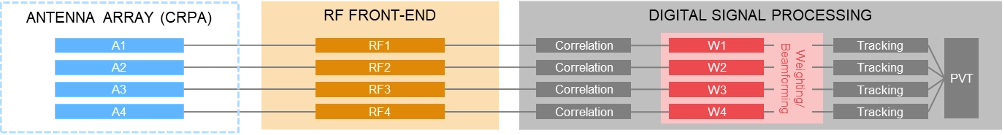
In contrast to using a single antenna with a fixed antenna pattern, some receivers use an adaptive antenna array, also referred to as controlled reception pattern antenna (CRPA). The idea is to weigh the signals received by each element according to dedicated optimization criteria. Typical optimization criteria are to minimize the signal’s output power towards a dedicated direction (“null-steering”), or to maximize the signal to interference or signal to noise ratio (“beamforming”). The underlying receiver architecture is more complex as signal weighting mechanisms must be added to the signal processing chain. These can be integrated before the digital processing block (“pre-correlation”) or implemented as an additional processing step between the correlation and tracking stages in the digital signal processing section (“post-correlation”). Both approaches are very effective in mitigating jamming and spoofing attacks, as they can either form a null in the direction of a strong jammer/spoofer or form beams towards the wanted signals from GNSS satellites, thereby de-weighting any unwanted signals coming from other directions.
Pre-correlation architecture of a 4-channel CRPA receiver
Post-correlation architecture of a 4-channel CRPA receiver
Within the processing chain of a GNSS receiver, there are different approaches and methods to detect and mitigate interfering signals, which are summarized in the following table:
AGC monitoring
●
●
Monitoring of the gain in the AGC loop. A sudden drop of the AGC gain can be an indication of an interfering signal; detection of high-power interferers; low-power spoofing attacks very difficult to detect
Spectrum monitoring
●
●
Detection of interferers and jammers above the noise floor; especially suited for detecting CW interferers. Not suited for the detection of matched-spectrum jammers, spoofers and meaconing attacks as their spectrum is typ. identical to the GNSS spectrum.
Frequency domain adaptive filtering
●
●
Dynamically identifies and suppresses unwanted frequency components (e.g., interference or multipath) by adjusting (notch) filter parameters.
Pulse blanking
●
●
Pulse blanking is a time-domain interference detection and mitigation technique used in GNSS receivers to detect and suppress short-duration, high-power pulses, typically caused by pulse jammers or Radar transmitters. Monitors the incoming signal power in short time windows and “ignores” this signal part in case certain power level thresholds are exceeded. Effective to mitigate pulsed jammers, not suited for multipath mitigation or anti-spoofing measures.
C/N0 monitoring
●
●
Monitoring over time and/or comparison against theoretical max. value; detection of all types of interferers; low-power spoofing attacks very difficult to detect
Time jump detection
●
●
Time jumps (backwards or forwards) are clear indications for meaconing or spoofing attacks.
PVT monitoring, incl. RAIM
●
●
Example: The computed position can be constantly compared against a known reference position. Not possible to distinguish between jamming/spoofing or other environmental effects like multipath. This also includes receiver-autonomous integrity monitoring (RAIM) schemes, that can be considered as a special form of PVT monitoring.
Doppler monitoring
●
●
Compare Doppler against theoretical/geometrical values; monitored Doppler profiles may show irregularities in case of an attack. Difficult to be separated from environmental or atmospheric effects.
CMC monitoring
●
●
„Code minus Carrier“ observable shows irregularities and increased noise in case of an attack. Difficult to be separated from environmental or atmospheric effects.
Signal Quality Monitoring (SQM)
●
●
Sampling of the correlation function using a few correlators; can detect distortions of the correlation function resulting from multipath, jamming or spoofing attacks.
Massive multi-correlator monitoring
●
●
Continuous, high resolution observation of the code/Doppler space. Can be done during signal acquisition and tracking. Can detect multipath, jamming, meaconing and spoofing attacks.
Derived Test Requirements
Based on the typical threat signal and attack characteristics, as well as the receiver-internal detection and mitigation methods discussed above, the test and simulation requirements listed in the table below can be derived. In addition to the requirements related to threat simulations (grey background), the table also contains “base requirements” for the simulation of realistic GNSS scenarios (blue background):
Testing: Methods, Setups and Challenges
The test methods, strategies and setups used depend on the architecture of the GNSS receiver being tested, the receiver features that need to be evaluated and the specific testing objectives.
A first categorization can be made by examining the origin of the GNSS signals being used for testing. The signals may come from real GNSS satellites and be used instantly and on-site (live GNSS testing) or recorded, stored, and played back in the lab (record/replay). Alternatively, testing can be done entirely in a lab environment using GNSS simulators. There are also hybrid test methods that will be discussed later in this article. In comparison to using real GNSS signals – either via live testing or the record/replay approach – using GNSS simulators in a lab environment offers significant benefits.
Simulation vs. Live GNSS Testing. One major drawback of using live signals is that the system conditions are often unknown at a given point in time, and – most importantly – they change over time. The locations of the satellites — and thus the geometric conditions — change as the satellites move along their orbits. Errors, such as atmospheric effects, are also time- and location-dependent. One of the most unpredictable error influences is multipath. The magnitude of multipath errors depends on a variety of different parameters, including the number of reflections, the distance between the reflection points and the antenna or the strength of the reflected signal. The latter is determined by the material properties of the reflecting surface. Both the geometric conditions and the material properties of the reflectors change or may change over time – the geometric conditions due to the permanent motion of the satellites and the reflector properties due to meteorological influences like rain, dew, or snow.
As a result, when using live signals, one must expect that the conditions change permanently and unpredictably and will never be the same for two distinct points in time. It is therefore very unlikely that two successive test runs can be performed under identical conditions. Repeatable testing, which is one of the most important test requirements, is impossible when using live GNSS signals.
Well-defined and controlled simulation conditions can only be ensured by using a GNSS simulator. A simulator typically offers fully customizable and repeatable scenarios (i.e., one and the same test scenario) that can be repeated as often as needed, producing the same signals with the same characteristics. Moreover, a simulator is often a more cost-effective and efficient solution, whereas using live signals would be time-consuming, complex, expensive or even impractical (e.g. test of airborne and spaceborne receivers).
The following discussion of typical test setups therefore focuses on the use of signal generators for GNSS testing. In terms of test scenarios, the focus will be on jamming, spoofing and coexistence testing. Testing against multipath influences is not specifically discussed below.
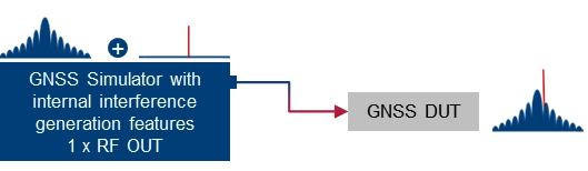
Basic simulator setups. The basic approach for testing against GNSS threats is to combine a “clean” reference GNSS simulation scenario with interfering signals and add the combined signals to the device under test (DUT). This basic concept can be implemented using two separate signal generators or an integrated solution that combines GNSS simulation and threat signal generation in a single instrument. Based on the architecture of the integrated solution (1 RF output vs. multiple RF outputs), GNSS and interfering signals are already combined internally, or GNSS and interfering signals can be fed to different RF outputs and combined with an external combiner before fed to the DUT.
Using two separate signal generators for GNSS threat testing. The interference generator (red) can either be a second GNSS simulator for generating spoofing signals or any other signal generator providing non-GNSS signals for jamming or coexistence tests.
Using a GNSS simulator with integrated interference generation capabilities. The signal generator features 1 RF outputs. GNSS and interfering signals are combined internally. An external combiner is not needed, but the dynamic range between GNSS and interferer (J/S) is usually limited.
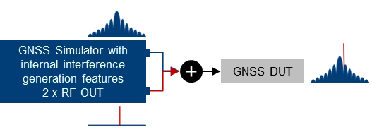
Using a GNSS simulator with integrated interference generation capabilities. The signal generator features 2 RF outputs. GNSS and interfering signals fed to individual RF ports and combined externally. This requires an external combiner, but with the benefit that very high J/S ratios can be achieved.
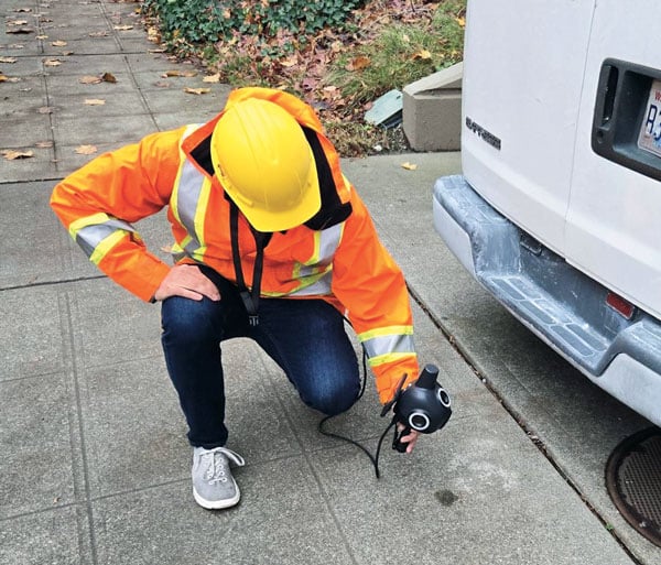
Conducted testing vs. OTA testing. The basic setups introduced above only work if the receiver has dedicated and accessible input connectors to feed the antenna signal to the receiver’s front end. This is sometimes not the case, so that conducted testing is not possible and over-the-air (OTA) tests must be considered. A classic example of such DUTs is mobile phones, where no antenna connector is available, at least not without dismantling the device.
Testing such devices against interfering signals is still possible by using a shield box. The shield box has an RF input to feed in the combined GNSS and interfering signals. The signals are then retransmitted into the inside of the box and the DUT uses its integrated antenna to receive and process the signals coming from the GNSS simulator.
Using a GNSS simulator in combination with a shield box to test GNSS devices with integrated antennas.
OTA GNSS threat simulation using a shield box with 2 RF inputs and 2 transmit antennas. The GNSS signals and the interfering signals are fed separately (uncombined) into the shield box.
An alternative setup is to use a shield box with two RF inputs. In this case, the wanted signals and the interfering signals are not combined externally but are fed to the shield box via separate RF input connectors and transmitted to the GNSS DUT via separate transmit antennas.
Additional aspects and challenges must be considered when performing OTA tests using mobile phones as a GNSS DUT. This includes conducting a proper cold start, removing all preexisting navigation-related information from its memory, and disabling any other sensors that may contribute to computing the phone’s position, including any assisted GNSS services. This is typically not a concern for most standalone GNSS receivers that feature dedicated cold start procedures and usually have no other positioning sensors on board. On the other hand, initiating a real cold start for GNSS modules in mobile phones can be tricky. Just rebooting the phone does not necessarily work, and the availability of dedicated settings also depends on the phone’s operating system (e.g. iOS vs. Android).
Another challenge during OTA testing of mobile phones is how to assess and analyze the impact of any interfering signals on signal acquisition, tracking and positioning. This requires detailed analysis and monitoring features on the mobile phone, which are typically not a standard feature of the phone’s operating system. Specialized GNSS monitoring apps can be used instead. To get access to the data during the test, special screen mirroring apps can be installed on the mobile phone.
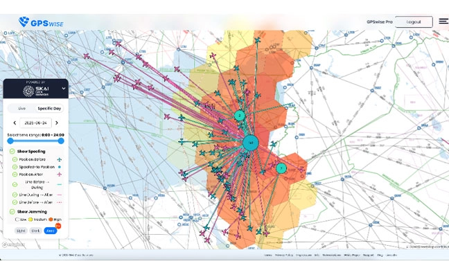
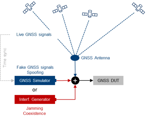
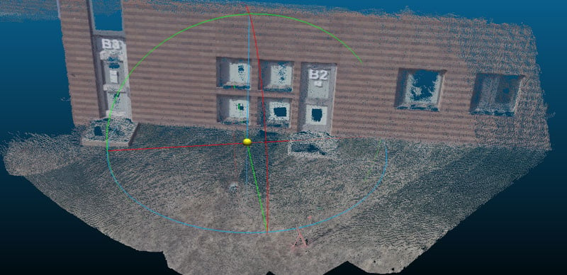
Testing with live signals. GNSS tests may also be performed in combination with live GNSS signals using already existing field infrastructure such as GNSS receivers installed at mobile base stations. A typical use case is to add one or several jamming/spoofing signals, or even an entire (stronger) “spoofing constellation” to an existing “live GNSS constellation” and test how the GNSS receiver reacts to such an attack. The typical test setup is illustrated in Figure 4.
Photo: Figure 4. The receiver’s response to interference is evaluated by introducing jamming or spoofing signals, alongside normal satellite signals using existing field infrastructure. This setup is often used to assess reactions to attacks.
This approach may be a good alternative to simulating everything with a GNSS simulator, as much more HW, i.e., more GNSS channels and more RF paths, are required with a simulator-internal approach. On the other hand, there are also some challenges associated with this test method, e.g., the signal generators, which need to be operated in a field environment. Moreover, for more sophisticated spoofing attacks, a prerequisite is the capability to time-synchronize the GNSS simulation with the live GNSS constellation.
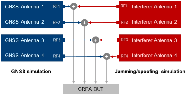
CRPA testing. For testing GNSS receivers with multiple antenna inputs, particularly CRPA systems, several RF sources/paths need to be combined and synchronized. The following illustration shows a possible setup for testing a 4-channel CRPA receiver against jamming or spoofing attacks. It is based on the 2-path architecture introduced above. It consists of two signal generators for generating GNSS signals for each antenna (left part of the setup) and two signal generators for generating the jammer/spoofer signals (right part of the setup). GNSS and interfering signals are combined per antenna element and fed to the RF inputs of the CRPA receiver under test.
For CRPA testing, generating phase-coherent signals is a must, i.e., it must be ensured that the phase relations between the GNSS signals and between the interfering signals represent the actual geometrical conditions and, above all, remain consistent throughout the simulation. To achieve this, a common LO signal needs to be used for generating the GNSS and interferer signals in all signal paths.
Another challenge is related to calibration. To correctly simulate the directions of the satellite signals and the interference signals, the test system must be calibrated at the RF interface to the DUT with respect to amplitude, phase and propagation time. This means that the amplitude, phase and propagation time differences between the individual RF paths, resulting for example from cables orRF components, must be compensated.
Rohde & Schwarz Solution
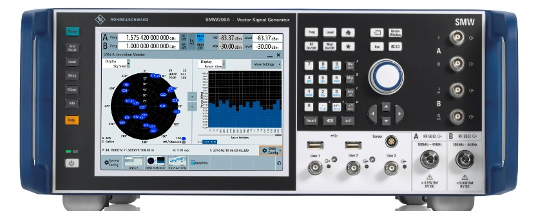
With GNSS test solutions from Rohde & Schwarz, all the relevant requirements for testing GNSS receivers against GNSS threats can be addressed. Available test solutions range from simple, single-channel, waveform-based signal generation with limited simulation time up to multi-frequency, multi-constellation GNSS simulators with 2 RF outputs, hundreds of GNSS channels and internal threat simulation capabilities, including non-GNSS signals for jamming and coexistence tests. For these advanced GNSS tests, the R&SSMW200A high-end vector signal generator is the ideal choice. It can be equipped with a multitude of GNSS options and feature sets.
Photo: Testing against GNSS threats with the R&S SMW200A
Jammer simulation. There are several ways to generate jamming and coexistence signals with Rohde & Schwarz signal generators in general and especially with the R&SSMW200A. Simple interference signals like noise or a CW interferer can be generated by using an optional integrated noise generator. For coexistence testing, the instrument can be equipped with signal generation capabilities for various standard-conforming communication signals, such as LTE. Customized interferer signals in the form of waveform files can be created by external software tools like MATLAB or Python and replayed by the instrument.
Customized jamming signal as well as entire jamming and coexistence scenarios can also be created using the R&SPulse Sequencer. The software allows to generate typical simple GNSS jamming signals like CW interferer, frequency sweeps, or pulsed interferers, but also complex jamming scenarios with consideration of moving interference sources and moving GNSS receivers, user-defined antenna patterns and scans. Depending on the signal characteristics, the jammer and receiver positions and the antenna arrangement, the software calculates the correct amplitude, phase angle and signal propagation times for the jamming signals.
Further reading
[1] Curran, James T. et. al. (2017): A look at the Threat of Systematic Jamming of GNSS, InsideGNSS, September/October 2017
[2] Dovis, Fabio et. al. (2015): GNSS Interference Threats and Countermeasures, GNSS Technology and Application Series, Artech House, 2015
The intriguing paradox about the information age is that it relies on semiconductor chips, which are fundamentally made from sand (silicon dioxide) — the most tangible and seemingly infinite resource on Earth. Yet, in 2023, the global digital storage capacity reached 110 zettabytes (110 followed by 21 zeros), which is a staggering figure; in fact, it is 15,000 times more than the number of grains of sand on Earth and it’s doubling every three years. The information age is suffering from excess information. Data is consuming the universe.
The velocity and quantity of information are overloading the ability to process it. This causes data-driven decision-making systems to fail. The limiting factor is human cognitive capacity to select, prepare and process the data, plus the ability to analyze it for meaningful insights. It is reminiscent of the early days of the Corona satellites of the TALENT KEYHOLE (KH) mission series that began in the 1950s during the height of the Cold War.
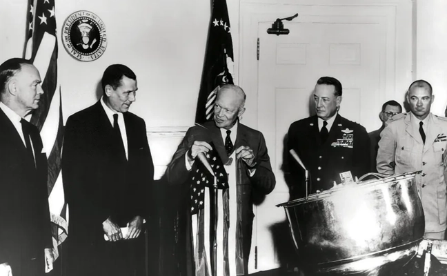
Understanding activities behind the Iron Curtain was critical for national security. The KH satellites were expensive to launch and had short life spans. They used rolls of wet film dropped from space and captured by specialized aircraft with hooks to catch the canisters in mid-air. The low-resolution images (3 m to 5 m per pixel) were processed manually in darkrooms. Teams of 100 specialists, using razor knives and scotch tape, meticulously pieced together image strips into massive mosaics spanning several square meters. Working around the clock, assembling the full image would take up to five days, with subsequent analysis requiring another week. In total, from catching the film canister to delivering a final intelligence report, it took 17 days — a testament to imagery intelligence in the industrial era, characterized by massive operations demanding significant time and manpower, but it was too expensive and unsustainable.
Photo: PRESIDENT EISENHOWER awards Capt. Mitchell, USAF, C-119 pilot, the Distinguished Flying Cross for the first ever capture of
a film cartridge dropped from space, in a photo circa 1960. cia.gov/resources/csi/static/corona.pdf
“We live in a world where there is more and more
information, and less and less meaning.”
— Jean Baudrillard,
“Simulacra and Simulation,” 1994
In 1976, the technological landscape shifted dramatically with the launch of the KH-11 satellite, which could transmit 15 cm resolution images digitally to ground stations and was capable of distinguishing objects as small as a dinner plate. The satellite dramatically compressed intelligence-gathering timelines. Processing and analysis time decreased from 17 days to mere hours. The first digital image was shown to President Carter. That first image is believed to be of ongoing tensions in the Middle East, but it symbolized more than the triumph of technology; it represented a fundamental shift marking the end of the industrial era and ushered in the information age.
Advancements in imagery were paralleled by developments in mapping, driven by the need for accurate spatial referencing. Various technologies throughout the 1970s offered partial solutions, but a solution did not happen until 1981 when Esri introduced Arc/INFO, a breakthrough geographic information systems (GIS) software that could operate on minicomputers instead of huge mainframes. That formed the basis of modern spatial analysis and visualization technologies; coming together with digital imagery is what allowed the information age to overtake the industrial era.
In 2025, a similar technological transformation currently is underway. As the amount of information overwhelms existing systems, artificial intelligence (AI) is emerging as the solution. The information age is transforming into the intelligence age, where big processing meets big data. Advanced algorithms, machine learning and large language models (LLM) can swiftly and efficiently handle vast amounts of information. So, with data being the new oil, AI is the refinery.
TheEsri Federal GIS Conferencein February could have been promoted as the “Dawn of GeoAI” conference. The term Geo AI is a subset of Spatial AI, and it is in its infancy. Esri is incorporating AI into many of its applications. Companies at the expo were teasing Spatial AI solutions in their products and services.
What is Spatial AI?
When the transformative power of AI is combined with spatial information systems, magic happens. Value is created that did not exist before.
Spatial intelligence is the ability to think, visualize and understand in three dimensions. It is one of the primary types of intelligence. Currently, Spatial AI is capable of interacting with analysts using natural language to build models and perform tasks. Similar to so much else happening with AI, its capabilities are increasing rapidly.
Photo: A CORONA SATELLITE image of Moscow captured May 28, 1970, as part of the TALE…
With iterative learning, the AI repeats a task millions of times on various training data to perfect its abilities, running through different scenarios multiple times with different datasets while completing multiple tasks. The AI quickly learns and can eventually surpass humans. This makes AI a super tool.
Combine that capability with AI’s ability to access and infer an entire compendium of knowledge on a subject. The AI is able to ingest text, images, audio and video in minutes, and then reason and understand them all within the context of the parameters provided. Through its own AI agents, it will automatically run functions to garner insights, and then communicate those results through data visualizations, text, audio and natural speech. Spatial AI is an evolved form of AI able to understand data in the context of space and time within the body of knowledge it can access. It will monitor everything in real time to identify anomalies and hidden patterns and provide deep insights. It doesn’t just solve the information overload dilemma for data-driven decision-making, but it enhances it far beyond expectations.
The Coming World of AI Assistants
The future is already here. Reality is approaching science fiction at warp speed. A person living 100 years ago would only be able to understand the world of today as magic; and likewise, the world 20 years from now will appear magic to us.
Interfacing with a Spatial AI system is similar to the multi-dimensional world we already exist within. Flat screens, keyboard and mouse will be secondary tools behind natural language and natural gestures and immersive experiential environments. The Spatial AI- enabled world will blur the lines between what is virtual and what is real. Jobs, businesses and the economy already are transitioning. The most well capitalized businesses are investing in this new technology.
One of the industries at the forefront is healthcare. Imagine you are a neurosurgeon. Your patient has a glioblastoma identified by the MRI/CT scans uploaded into the Spatial AI Medical Assistant called SAIMA (pronounced Sāmă; when speaking with the system, you call it “Sammi”). The MRI/CT scans show a 3D model of the patient’s brain, highlighting the glioblastoma in red. Placing the integrated augmented reality (AR) glasses on, you can zoom in on the glioblastoma to see the extent of the growth and view it from any angle. This helps formulate a surgery plan. The patient’s medical records are in SAIMA along with the corpus of knowledge about glioblastomas. SAIMA is regularly updated with the latest algorithms and models. After reviewing the preliminary data, you have SAIMA run the spatial analytics and all the applied functions on the data. It takes approximately 35 minutes to complete. During that time, you review the SAIMA updates and go to lunch. You receive a text message from SAIMA after it completes its processing, letting you know it is finished without encountering any issues. SAIMA works with a system called VisAR, which is a precision surgical navigation system. After returning to your office, you put on the VisAR glasses to begin the review. Sammi begins by showing you the glioblastoma and pointing out it is a large, heterogeneous mass located in the frontal lobe and appears to be 4 cm to 5 cm in diameter, in an irregular shape with nodular and cystic components. As it goes through the review, it zooms in and rotates the 3D image, highlighting the exact area being talked about. You interrupt Sammi during this review and ask if the patient has been experiencing motor function issues since the tumor is in the frontal lobe, and you continue to probe further in a natural conversational tone as you delve deeper into the analysis. The conversation between you and Sammi is recorded and added to the file.
The review with Sammi takes several hours, during which a high-confidence surgery plan is developed that you will present to the multidisciplinary tumor board, who will further query SAIMA. This thorough process ensures the best results and further trains SAIMA about glioblastomas, which will be used for a post-surgery debrief and for insurance purposes. Following a successful board meeting, SAIMA proceeds to reserve the operating room, schedule the patient, and create a detailed surgery plan with specific duties and exact times for each member of the surgical team. This plan is then disseminated to all members of the surgical team and preoperative staff. A detailed surgical procedure file is generated, which serves as a navigation file, similar to Waze or Google Maps, providing step-by-step instructions to guide the surgery. This file will be loaded into ROSA (Robotized Surgical Assistant), a high-precision robotic surgeon.
On the day of the surgery, you wear special Bluetooth gloves that are synced with the SAIMA/VisAR glasses and ROSA. In real-time, magnified between 15x and 40x, you observe ROSA surgically removing the cancerous tissue. Overseeing the process, you see a tumor that has spread beyond the original CT/MRI scan and zoom-in on the tumor, and you take control of ROSA to manually remove the tissue. The surgical system uses a “differential engine” concept to scale down the surgeon’s movements to match the magnification level of the procedure, allowing for precise and delicate tissue removal. This means that the surgeon’s natural movements are reduced to a smaller, more precise scale, enabling accurate and intricate procedures. For example, a 1 cm movement by the surgeon might be translated into a 0.1 mm movement of the robotic arm, allowing for high-precision work. The system is dependent upon a high-level of spatial intelligence to make those calculations in real-time.
Afterward, you return the surgery back to the automated control of ROSA to follow the surgical procedure file plan. Throughout the fully immersive procedure, you speak with Sammi in a calm, natural language and responsive manner.
The patient, a married middle-aged father of two, not only survives but thrives because of the accurate analysis of SAIMA and the precision of ROSA, with you overseeing the entire process. The Spatial AI-based surgical system allows you to do what you wanted to do as a neurosurgeon and save people’s lives.
Nothing is Permanent Except Change
Breakthrough innovations, such as the internet, have changed the world. Spatial AI is going to do the same. These technologically driven schisms are huge opportunities. One can only speculate how it will alter the future. Once a technology takes hold, and it becomes obvious there is no going back, its adoption will accelerate, and in those moments, careers make exponential leaps. Those in front of it will make substantial gains. Position yourself accordingly. Learn about Spatial AI and Geo AI. Carve out your own specialty, such as Spatial AI/AR (augmented reality), Spatial AI/VR (virtual reality), Spatial AI/XR (mixed reality), and Spatial AI/FMV (full motion video). The future is yours to imagine.
Photo: William Tewelow
WILLIAM TEWELOW is a designated Geographic Information Systems Professional. He has a master’s degree in Organizational Leadership with a focus on Performance Management, a bachelor’s degree in Intelligence Studies focused on geospatial intelligence, and an undergraduate degree in Geographic Information Technologies. William retired from the Federal Aviation Administration in 2025 after 16 years in various roles supporting geospatial information for aviation operations in the national airspace. He is a graduate of the management fellowship Program for Emerging Leaders where he served on special assignment to the Department of Transportation, leading a national strategic geospatial initiative under the authority of the White House Open Data Partnership.
“Seen & Heard” is a monthly feature of GPS World magazine, traveling the world to capture interesting and unusual news stories involving the GNSS/PNT industry.
West Point Cadets Map Electronic Warfare West Point cadets conducted a senior thesis project investigating the use of GNSS technology to map and visualize electronic warfare activities in the South Pacific, specifically focusing on GNSS spoofing. Their research, centered on the Huangpu River and Northeastern Shanghai, aimed to identify patterns of malicious GNSS interference and potential perpetrators, highlighting the strategic and economic motivations behind these actions in the region. By developing data visualizations of spoofing incidents, the cadets created a model that could be scaled up to analyze larger areas.
Credit: Eric S. Bartelt / USMA PAO-VI
South Africa Rising Above Water Researchers from the University of Bonn have found that South Africa’s land is rising by up to 2 mm per year, not because of deep mantle activity, but due to water loss from severe droughts. This uplift was detected using the TrigNet network of GNSS stations, which precisely measures changes in land elevation. As groundwater is depleted, the Earth’s crust rebounds upward — a process GNSS stations can monitor in real time.
Credit: THEGIFT777 / E+ / Getty Images
Türkiye to Launch Homegrown Satellite Navigation and Mapping System Türkiye is developing the Regional Positioning and Timing System (BKZS) to launch its own GPS and mapping application, in an effort to reduce dependence on foreign technology and enhance cybersecurity amid growing industrial automation. The system will provide precise location, navigation and timing data via Turkish satellites as an alternative to global systems including GPS, supporting critical sectors such as military operations, civilian communications, smart transportation, and precision agriculture.
Quantum Navigation System Serves as GPS Backup Q-CTRL, a quantum infrastructure software company based in Sydney, Australia, has demonstrated a new quantum navigation system, Ironstone Opal, as a backup to GPS technology. The Ironstone Opal system uses quantum sensors to detect variations in the Earth’s magnetic field, determining precise geographic coordinates with the help of artificial intelligence-based software. Ironstone Opal is passive and does not emit signals, making it resistant to detection and jamming. Field trials showed the system outperformed a high-end inertial navigation system and served as a reliable GPS backup by up to 50 times in ground vehicles and 11 times in aircraft.
As GPS World marks its 35th anniversary, we continue to evolve to meet the needs of our valued subscribers and marketing partners. This month, we unveil strategic refinements to our magazine publishing schedule and our expanding digital content and solutions portfolio plans.
Tod McCloskey
To better align with buying cycles and industry events, GPS World is transitioning from a monthly print and digital edition cadence to a six-times-per-year magazine frequency. Remaining 2025 issues are set for September and October. Beginning in 2026, GPS World issues will publish in February, March, May, June, September and October.
Each GPS World issue will continue to deliver exclusive technical content and market insights.
In tandem with our magazine’s evolution, GPS World is significantly expanding its digital content and media solutions offerings, including:
Expanding GPSWorld.com: We will feature more exclusive content, delving deeper into today’s hottest trends in GNSS’ and complementary PNT’s top segments: autonomous solutions, defense, mobile, machine control/precision ag, simulators, surveying, mapping and transportation
New Custom Media Solutions: Leading technology suppliers now have an arsenal of platforms and offerings to educate our audiences on trends and advancements
Expanding Enews: Navigate Weekly!, Survey Scene, Autonomous Arena and Defense PNT e-newsletters: We will deliver even beefier segment news to your inbox each week
GPS World’s audiences are highly engaged confirmed buyers/specifiers. We promise to continue to evolve our integrated media offerings to meet readers’ and marketers’ changing preferences — because you are, and always have been, at the center of our information constellation.
Read a roundup of recent products in the GNSS and inertial positioning industry from the June 2025 issue of GPS World magazine.
MOBILE
Mobile Clock Generators With an integrated MEMS resonator
SiTime’s Symphonic is a mobile clock generator built around the SiT30100, which integrates a MEMS resonator and a temperature sensor in a compact 2.22 mm² chip. Designed for 5G and GNSS chipsets, Symphonic delivers precise, resilient clock signals while supporting efficient power consumption in mobile and IoT devices, including smartphones, tablets, laptops and asset trackers.
The integrated temperature sensor feeds data to compensation algorithms, providing frequency stability as low as ±0.5 parts per million to enhance GPS accuracy and shorten lock times, which is critical for reliable performance in challenging environments. The device operates across a -30°C to 90°C temperature range and is engineered for dynamic stability and power optimization, helping to mitigate electromagnetic interference. Symphonic features four configurable clock outputs, each capable of delivering 76.8 MHz, 38.4 MHz or 19.2 MHz, suitable for baseband, radio frequency and GNSS applications. The single-chip design eliminates the need for external resonators.
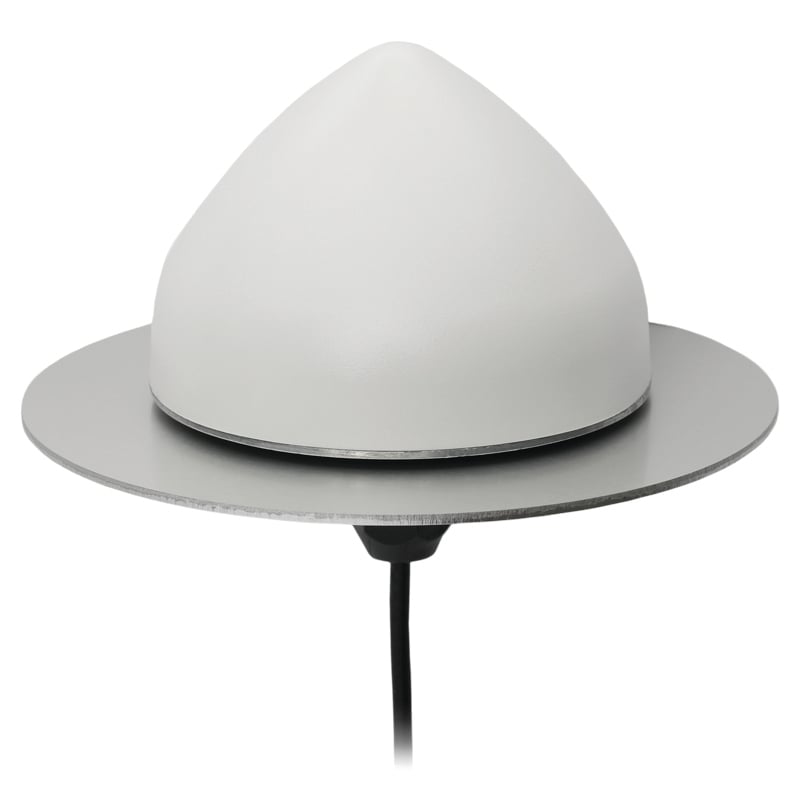
Dual-Band L1/L5 Antenna For critical positioning and timing applications
The TW3885TL is a dual-band GNSS antenna engineered to deliver reliable, interference-free signal reception for critical positioning and timing applications. Supporting both L1 and L5 frequency bands, the antenna is compatible with a wide range of global navigation satellite systems, including GPS, QZSS, Galileo, BeiDou, GLONASS and NavIC, as well as regional satellite-based augmentation systems. The TW3885TL incorporates advanced filtering technology designed to reduce interference from crowded radio frequency environments. It features a low-noise preamplifier, with a typical noise figure of less than 2.5 dB, and offers high gain, typically around 40 dB. The antenna maintains a low axial ratio, under 2.0 dB, and exhibits tight phase center variation, which contributes to precise timing and superior signal quality. Constructed with a weatherproof enclosure rated to IP69K, the TW3885TL is suitable for permanent outdoor installations and can be mounted through-hole, with optional accessories available to support various mounting configurations.
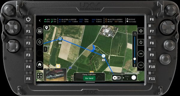
Software Upgrades Enable positioning in GNSS-denied environments
eBee VISION application software now includes a suite of updates for UAV navigation in environments where GNSS signals are compromised or unavailable. The latest software enables autonomous position updates with map referencing, allowing for precise navigation even when satellite signals are jammed, spoofed or blocked. This product is suitable for defense personnel, public safety agencies, and industrial teams working in high-stakes environments where GNSS signals are unavailable (densely populated urban areas, near critical infrastructure, or in contested zones with active interference). The update introduces optical flow stabilization for target lock, which uses visual cues to keep the camera centered on a point of interest during zoom-ins or drone movement. The software allows for adaptive behavior after GNSS recovery or visual repositioning. Additional enhancements include real-time mission duration and return-to-home estimates, optimized cruise speed in windy conditions, high-precision landings using lidar-based altitude calibration, a gimbal auto-recovery mechanism to clear obstructions mid-flight, and smart motor speed reduction to prevent overheating during extreme conditions.
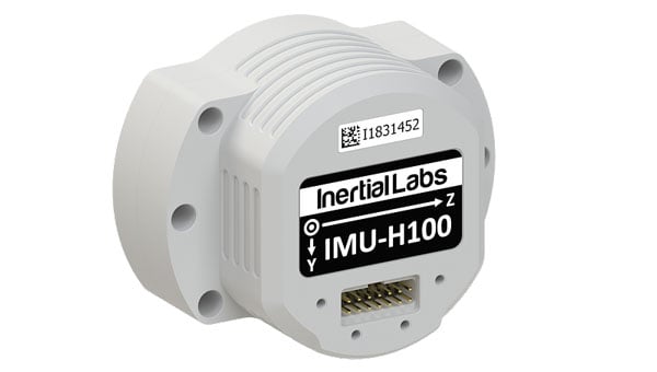
IMU For unmanned commercial and defense applications
The IMU-H100 is a micro-electromechanical systems inertial measurement unit (IMU) designed to improve tactical guidance and navigation for UAVs, short-range missiles, precision-guided munitions, and a range of commercial applications. The tactical-grade unit features accelerometers and gyroscopes on all three axes. It offers a gyro bias of 1° per hour and an accelerometer bias of 1 mg. The unit measures 5 in³ and weighs 160 g. The IMU-H100 surpasses comparable products in data rate, measurement range, stability and repeatability, even under challenging conditions such as vibration, shock, high acceleration, spinning, temperature changes and acoustic noise.
The Spatial Sciences Institute (SSI), part of the Dornsife College of Letters, Arts and Sciences at the University of Southern California (USC), is a national leader in geospatial research and education. Founded on July 1, 2010, SSI has been educating students and professionals with both the theoretical foundation and hands-on technical training to advance spatial thinking and geospatial technologies.
Graduates solve complex problems across diverse industries and domains such as environmental sustainability, geodesign, public health, human security and geospatial intelligence. Education and training with GNSS are integral to SSI’s mission.
Addressing the Generation Gap
Despite its fundamental importance, the GNSS workforce is facing a growing generational gap as many experienced professionals near retirement, and fewer young individuals enter the field. This decline in incoming talent poses a critical challenge for industries that rely on high-precision positioning, from infrastructure development and environmental monitoring to national security and disaster response.
Part of the challenge stems from a lack of early exposure and awareness among younger generations about the relevance and applications of GNSS technology. Many students encounter the topic only indirectly, if at all, in traditional STEM or Geography curricula.
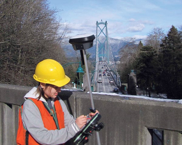
To preempt this generic approach, SSI has invested in high-accuracy GNSS receivers, RTK-enabled UAVs and immersive virtual/augmented reality visualization equipment to provide students the capability to translate the theoretical lessons in geodesy, spatial data acquisition, data analysis and integration into technical skills that result in actionable information.
Additionally, SSI has developed a range of experiential learning opportunities in GNSS to bridge the gap between classroom instruction and real-world GIS applications. While completing their coursework, students often solve the same real-world challenges as many industry professionals.
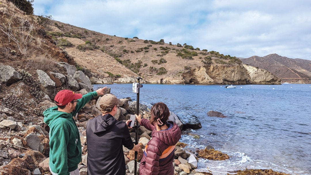
Engagement Through Experimental Learning
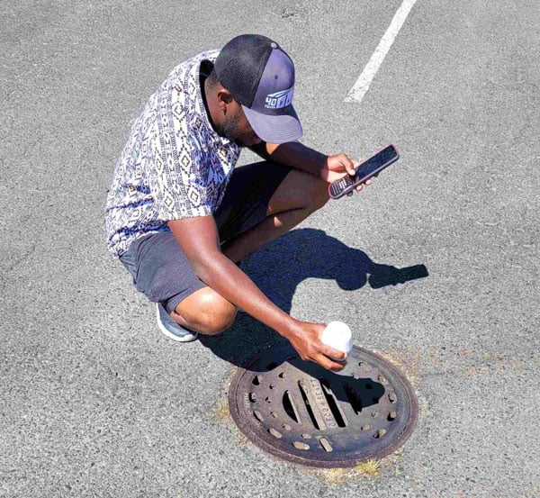
One such example is the undergraduate course SSCI 220L: Spatial Data Collection Using Drones, taught by Yi Qi, Ph.D., an associate professor with expertise in remote sensing and geospatial artificial intelligence. “When young students are introduced to imagery and geospatial technologies, one of the first questions they often ask is how the positions of real-world features are measured — and how accurate those measurements need to be for applications like building construction or urban tree mapping,” Qi explained. “This presents a great opportunity to introduce students to more advanced industry practices such as real-time kinematic (RTK) correction.”
Qi added, “We use the RTK-enabled DJI Mavic 3M drone for field data collections, which is often a highlight of the class.” One memorable field activity took place at the historic Los Angeles Memorial Coliseum, where students participated in drone flights alongside faculty. Before takeoff, they helped establish communication between the drone’s RTK system and the California Real-Time Network (CRTN), learning how to configure the system for centimeter-level accuracy. Later, they processed the imagery into high-resolution 2D orthophotos and 3D models. “This class benefits undergraduates by providing early exposure to GNSS,” Qi said. “This foundation is important for students to imagine their pathways in the geospatial industry and choose other advanced courses.”
At the graduate level, as part of the SSCI 587: Spatial Data Acquisition course, students are required to participate in a week-long intensive-learning field experience at the USC Wrigley Institute for the Environment and Sustainability campus on Catalina Island. Laura Loyola, Ph.D., assistant professor in SSI with specialties in ecological physiology and field data collection, has led this course for many years and acknowledges that, “Catalina offers the ideal location for rugged terrain data collection, practice with online or offline mapping, and incorporates spatial data collection utilizing the RTK-enable UAV and high-accuracy GNSS receivers, with spatial analysis and visualization methods.”
While on Catalina Island, students meet with industry partners, such as Isaiah Mack, the owner of Eclipse Mapping and GIS, and an alumnus of USC, who bring professional experiences and the latest technology from industry. “The question now facing industry is whether the added investment in both hardware and training of personnel on high-accuracy GNSS receivers for spatial data collection is viable and needed for everyday uses, especially with RTK and satellite-based augmentation systems (SBAS) available,” Mack said. “The answer is overwhelmingly yes, with many mapping and GIS professionals utilizing centimeter-level RTK accuracy, so I feel it is important to share with students the growing market for these careers.”
Students quickly learn that without a viable connection, such as Wi-Fi or Starlink in remote areas, RTK capabilities in the UAV are limited. This requires the ability to incorporate high-accuracy ground control points into their collection workflows for georeferencing the drone imagery. As students work through the image processing and integration workflow, they gain firsthand experience in how GPS accuracy influences final image quality. Loyola noted, “In remote environments where WiFi connectivity is limited or non-existent, smartphone positional accuracy is decreased even more from the standard 30 cm to 50 cm, forcing students to work offline and with external GNSS receivers.”
Lastly, in certain field scenarios where students are unable to physically reach the survey target, they have learned to apply alternative methods to ensure accurate data collection. One effective technique involves using a laser rangefinder to measure the distance to the remote object. By combining this distance measurement with GNSS-derived position and bearing data, students can use in-app tools to calculate the location of otherwise inaccessible features. These experiences not only demonstrate their problem-solving abilities in challenging environments but also reflect a practical understanding of integrating complementary technologies to achieve high-precision geospatial results.
GNSS also has been integrated into the geodesign programs at SSI. Guoping Huang, Ph.D., is an associate professor with specialties in landscape planning and geodesign. “High-accuracy GNSS has become increasingly important in the architecture, engineering and construction sector due to the growing adoption of geospatial workflows,” he said. “These workflows span the entire project lifecycle — from spatially-enabled design tools that help create context-aware and environmentally responsive plans, to precision construction, where GNSS-integrated technologies such as sensor networks are used to monitor construction activities in real time.”
This integration ensures that construction adheres closely to the original design intent, minimizes costly deviations, and helps avoid damage to critical infrastructure. As a result, high-accuracy GNSS supports not only greater efficiency and accuracy but also enhances safety and sustainability in complex construction environments.
Empowering the Next Generation
By integrating GNSS into education programs and engaging students through practical fieldwork, faculty in the spatial sciences spark interest and develop the next generation of geospatial professionals. These efforts are essential to sustain the workforce and fuel innovation in a field increasingly critical to smart cities, climate science, autonomous systems and beyond. The experiential learning has inspired young generations to enter the geospatial workforce and make immediate, transformative impacts on existing practices.
Student Evelyn Vega commented, “The concepts and hands-on experience from course SSCI 220L helped me understand and appreciate GPS technology.” Recent graduate Yimiao Wang, who now works with the County of Riverside, California, has directly applied the GNSS data collection and processing techniques learned in course SSCI 587 to her work in roadway deterioration detection with RTK-enabled drone imagery. Her ability to leverage high-accuracy GNSS not only enhanced the quality and efficiency of her team’s outputs but also led to her career development success. These examples illustrate how GNSS education can empower students to drive innovation and advancement in the public sector and beyond.
What urgent policy or industry actions are needed to protect and advance resilient PNT services amid spectrum sharing debates and GNSS regulation changes?
Jules McNeff, vice president, strategy & programs, Overlook Systems Technologies
In my article, “Is There a Silver Bullet for Resilient PNT?”, I addressed the confusion caused by the numerous and diverse industry initiatives now being offered. Industry is understandably motivated to provide resilient PNT capabilities, but each also wants the government to pick its solution and make policy decisions accordingly. Spectrum sharing decisions that favor a single service provider may harm others in a crowded space, and so are difficult or impractical, as we have seen with the decades of litigation associated with LightSquared/Ligado and the spectrum surrounding the GPS L1 frequency.
Not everyone can win that competition, and as I noted at the end of the article, “Unless our government accepts responsibility, there will be no PNT silver bullet for domestic CI. Experience shows that industry will not solve this problem alone.”
For years, I have advocated that U.S. PNT technology policy be managed and services acquired holistically as vital dual-use civil/military capabilities. For the civilian community, that means making sure the national leadership understands the reliance our domestic critical infrastructure (CI) has on constant access to precise PNT to maintain continuity of operations across all CI sectors in the face of well-known threats. The leadership must then decide whether that reliance deserves proactive attention by the government to ensure PNT continuity is not disrupted.
Several years ago, I suggested that significant regulatory changes were needed in how civil PNT services were handled throughout U.S. CI. Both the Departments of Homeland Security and Transportation were assigned responsibility in Presidential Directives for finding a GPS backup to PNT services in domestic CI. I won’t revisit that years-long debate (which is still unsolved), but I will revive the framework of the suggestion.
The DOT has overall responsibility for civil agency PNT matters, and DHS frequently cites lack of regulatory authority as a limitation on its ability to encourage compliance in the CI sectors for which it is responsible. Therefore, I suggested that the National Space-Based PNT Executive Committee consider regulatory changes to expand the definition of the Transportation CI Sector to include safe and uninterrupted transportation of all elements contributing to domestic critical infrastructure. In addition to current air, road, rail, and oil/gas pipeline transportation, add the interstate transport of information (Communications and IT), electrical energy (Power Grids), economic transactions (Finance), crops (Agriculture), and water, as well as domestic maritime services (U.S. Coast Guard) and possibly emergency response services in the case of large disasters.
In the spirit of the former Interstate Commerce Commission, which years ago was replaced by a DOT Surface Transportation Board (primarily concerned with freight rail), the DOT may then seek expansions to STB authorities and membership to address the PNT dependencies and vulnerabilities affecting those fundamentally transportation-oriented activities vital to the viability of all U.S. critical infrastructure sectors.
— Jules McNeff Overlook Systems Technologies
Miguel Amor, chief marketing officer, Hexagon’s Autonomy & Positioning Division
Regulatory authorities must quickly approve and protect RF spectrum allocated for new PNT capabilities, particularly for emerging low-Earth orbit (LEO) constellations. These systems offer clear advantages in signal strength, geometric diversity and resilience against jamming and spoofing. Without timely and well-defined spectrum authorization, along with strong adjacent-band protections, the deployment of GNSS receivers capable of supporting these constellations will be delayed.
On the industry side, LEO PNT developers must urgently finalize signal structures and release Interface Control Documents, enabling GNSS receiver manufacturers to begin implementation, validation and system integration.
— Miguel Amor Hexagon Positioning Intelligence
Mitch Narins, Strategic Synergies
Interesting and timely question. I’ve written quite a few pieces and papers on the need for resilient and robust PNT services. If I were to point to a single thing that has held the US (and many other countries in the world back (except for China) it is lack of strong mission-oriented, dedicated leadership. It has been said that the definition of a committee is an entity with four or more legs and no brain. It is time to designate a single entity and a single office and a single person as responsible for ensuring resilient PNT services to US critical infrastructure so as to maintain the safety and security and economic benefits these these sectors support. Some wise men once came up with the idea that a government must “provide for the common defense” and “support the general welfare.” Resilient PNT is essential to achieving both.
In addition to the lack of empowered, centralized PNT leadership, a key problem that has impeded progress towards resilient PNT is the lingering belief by many that given enough time and money and spectrum, GNSS-sole means is achievable and that all non-GNSS systems (affectionately called “Legacy PNT Systems”) can be discontinued. In fact, over the years budget justifications for GNSS systems have used discontinuance of ground-based systems as “a benefit” to balance out the costs of establishing, updating, and operating GNSS.
Engineering System Designer should never fall in love with their solutions. The mission, i.e., the needs of the customers must always remain their first concern. After many years, integrity was added to the list of PNT metrics; coverage has yet to be officially added. Yet, even today, there remains confusion regarding the availability metric and the associated risks. For GNSS systems, the risk of losing required PNT metrics should always be considered “1.0”, and therefore, for critical infrastructure users and providers, require effective and implementable contingency/continuity of operation plans. Loss of PNT performance (accuracy, availability, integrity, continuity, and coverage) the using GNSS can no longer be considered a “Black Swan” event.
— Mitch Narins Strategic Synergies
In the February 2025, Professor Washington Ochieng proposed the following question to the GPS World EAB.
When we discuss the security of GNSS/PNT systems, we nearly always focus on interference — i.e., meaconing, intrusion, jamming or spoofing. However, GNSS/PNT systems are embedded in systems of systems that also offer many other opportunities for cyberattacks. What should we do about it?
I have thought for some time about why this is an issue. This is an interesting question, and the answer should be straightforward – but it’s not. For whatever reason, it seems many in the “cyber community” believe they are different, somehow, and apart. This has been apparent to me in dealing with those in the cyber community regarding their PNT dependencies and vulnerabilities going back to the creation of USCYBERCOM as a separate combatant command within the DoD. Those in the cyber world seemingly do not see a need to recognize and account for the intersection of PNT and cyber as mutually integral parts of a broader Information Technology ecosystem. Yet, across that entire IT ecosystem, PNT is simultaneously an enabler and a product of IT functionality, as communications and data systems could not operate without it, and it is likewise vital to IT users in executing their diverse missions. Ultimately, interference effects, whether from jamming or spoofing in their various forms or from digital intrusions of one kind or another, disrupt vital elements of that IT ecosystem. Our national and economic security depend on the continuous, reliable, uncorrupted functioning of IT services enabled by and delivering PNT information. So, a straightforward but difficult to implement answer is that we need formal education programs to routinely inform the leaders of industry and government (and the public) of the ubiquitous, vital role of positioning and timing (what we call PNT) throughout all the systems-of-systems whose operation depends on the IT ecosystem – and how to tell if something is amiss.
Anyone who has had to carry cumbersome legacy surveying instruments over rough terrain can probably confess to daydreaming about having something like Mr. Spock’s “Tricorder,” a small device that captures everything about your surroundings. Such sci-fi devices anticipated the “reality capture” wave of the present day.
Multi-sensor stacks have become the norm and are essential for many geospatial applications. Consider vehicular autonomy. For safety-of-life considerations, no single positioning technique could suffice. Each sensor type has strengths and weaknesses. Lidar has good behaviors under certain conditions: radar, GNSS and inertial measurement unit. That is why a typical autonomy stack will include one or more sensor types. More data of different types is better, especially if it can share a common, highly precise spatial reference. Surveying and mapping are benefiting laterally from the research and development for autonomous solutions. In some ways, autonomy solutions have benefited from the long-standing legacy of research and development in geomatics applications.
Platforms, Positioning and Progress
As surveying and mapping practitioners, we are bombarded with news and ads for a seemingly endless parade of the latest reality capture devices: handheld SLAM scanners, drone payloads, mobile mapping systems, backpacks and more. Many are using OEM sensors from a relatively small subset of manufacturers; this trend is similar to the wave of third-party GNSS rovers a decade ago.
While the individual sensors deliver astounding data, integration into field capture devices often shortchanges one crucial element: positioning. There is a tendency to keep cost, size, and power consumption low by including positioning components (e.g., GNSS and IMU) originally developed for mass-market applications like vehicle autonomy. Not every handheld SLAM system can afford to add survey-grade capabilities, like that delivered by dedicated surveying rovers costing tens of thousands of dollars, so users need to have realistic expectations.
A surveyor might wince when they hear a marketing claim from yet another SLAM device manufacturer claiming, “centimeter precision, anywhere!” Even with top-tier survey rovers, skill and experience temper such expectations. But what if the platform of a highly capable, survey-grade rover, packed multiple data capture sensors? This idea is not new, and the evolution of rover-based solutions in many ways, enabled the development of the current wave of reality capture systems.
Positional Integrity Through Motion
It is a prospect that might seem counter-intuitive: deriving a precise position while moving the instrument. Providing tilt compensation for a GNSS survey rover (on a pole/rod) had long been desired. The impetus was to improve efficiency, namely by removing the time spent leveling the rod for each observation. Freeing the user from the tyranny of the bubble was one goal, but it was also the first crucial step in being able to enable further sensor integrations.
Integrity through motion is one of the foundational elements of GPS/GNSS: the trajectories of the navigation satellites can be predicted with high confidence. For example, frequently updated ultra-rapid orbit products utilized in many GNSS solutions rival the “precise” orbit products we used to wait days for. Similar principles apply to modern tilt compensation solutions. The movement of a rover head provides a highly predictable reference trajectory for the orientation of the tilt sensors.
Electronic bubbles and tilt compensation have been around for many years. For example, compensators are standard in many instruments, such as total stations, and tightly coupled GNSS+IMUs in mobile systems for road, sea, and airborne mapping. Consider the SPAN system from Hexagon | NovAtel. Such systems compute centimeter-grade positions for moving cameras, lidar units, and other sensors, while taking into account heading, speed, pitch, yaw, roll, and in the case of marine systems, heave — at highway speeds, plowing through rough seas, or zipping across the sky. The challenge, though, was miniaturization. Could such capabilities be developed to fit into a standard survey rover?
Tilt compensation in rovers began to appear over a decade ago. For example, in some JAVAD rovers of the day; other manufacturers were soon to follow. These were at the time, unfortunately, magnetic-oriented systems. While a noteworthy achievement, the inconsistencies inherent to magnetic reference and cumbersome calibration routines soured a lot of users to the idea of tilt compensation.
The Leica GS18T marked the beginning of the multi-sensor stack trend for GNSS rovers, introducing no-calibration tilt compensation in 2017. This was soon followed by the GS18I, adding a camera for offset points, stakeout, and point cloud creation. Since then, such features are common across the industry. (Photo: Gavin Schrock)
This changed with the announcement by Leica Geosystems at the October 2017 INTERGEO international exhibition and conference in Berlin of the no-calibration tilt-compensated Leica GS18 T GNSS rover. This was one of the first “stacked rovers,” spawning a chain reaction of similar feature integration across the industry.
“The main thing we wanted to do was to make measurements faster for the user,” said Bernhard Richter, vice president of product management geomatics at Leica Geosystems, when I interviewed him at the time of the GS18 T launch. The process was part of a 10-year initiative to improve field efficiency, but it was not the sole goal. Dynamic precise positioning was the first step to enabling the integration of additional features.
After a year or so of end users getting over the skepticism of tilt compensation, you will now find it as a standard feature on nearly all new GNSS rovers. Of course, users need to verify and build confidence in new solutions. Surveyors of a certain age might remember when nervous party chiefs would require taping/chaining of distances to verify if those “new lasers” were working right.
Adding Sensors
GNSS in sky-view-challenged environments was the impetus for the first multi-sensor integrations. Namely, how to get the shot under the adjacent canopy, or roof overhang. While manufacturers and integrators had been offering various ranging lasers as peripherals GNSS rovers since the late 1990s, the Achilles heel was the orientation; limited to magnetic references. Despite this handicap, such offset point solutions were popular for certain applications (e.g., asset inventory, trail mapping).
Once dynamic precise positioning was achievable in a rover head, it could become a platform for additional data capture sensors. Cameras were the logical first step. A camera included on some JAVAD rovers was leveraged by some users for photogrammetric computation of offset points. Leica Geosystems soon followed up its GS18 T, with the GS18 I, which added camera-based offset point capabilities. Rather than some early photogrammetric offset point solutions where you took individual static photos, with the GS18 I, you capture a series of precisely spatially registered images while in motion. In the companion Leica Captivate software, you can quickly identify the offset points. The same images can be processed in the software as a 3D point cloud, which many users do.
Again, we started to see camera-based offset point (and stakeout) solutions in nearly every brand of GNSS rover. What’s next? We’re starting to see lidar added to some rovers. But at what point should a field user reach for a dedicated reality capture device, rather than trying to do everything with an enhanced GNSS rover? There’s a lot to consider, so we asked some integrators for insights.
Eric Gakstatter, principal and owner of Discovery Management Group, has been promoting multi-sensor at conferences for decades. His firm also has developed and consulted on such sensors in conjunction with various manufacturers. Gakstatter highlighted some successful sensor integrations.
“There’s a difference between, say, those lidar SLAM devices and rovers,” he said. “With one, you are looking for a point cloud, but with the other, you are more interested in discrete points of interest; you’re very deliberate in measuring specific features.” Gakstatter had recently given me an overview of the Eos Positioning Systems Skadi GNSS rover, a next-generation receiver from the makers of the Arrow GNSS receiver systems. The Skadi features a built-in antenna and full tilt compensation, but also can be paired with a companion smart handle that offers some interesting multi-sensor capabilities. First, there is a “virtual pole” feature that wirelessly measures the distance straight down to the ground, eliminating the pole for certain applications. Another feature is a ranging sensor with a visible laser pointer for offset points and stakeout. “You can pull the trigger and trace along a curb line, collecting points in a continuous mode,” said Gakstatter. “It’s literally point and shoot simplicity.”
The Eos Positioning Systems Skadi rover fits on a pole, or this handle with automated height-above-ground and offset features measurement sensors. (Photo: Eric Gakstatter)
His firm has also developed, in partnership with another manufacturer, an angle encoding peripheral that mounts on the pole. When used in conjunction with a rangefinder-style laser, the GNSS rover can perform traverses in much the same manner as a surveyor’s total station. In a field demonstration for a utility services company, the crew did such a traverse along a roadway, then under canopy, in the shadow of tall buildings, inside a covered parking garage, and then closing back on the beginning outdoor points. This process would have taken much longer with conventional instruments.
While a strong advocate for multi-sensor integration, Gakstatter points out some of the challenges. “It just takes so long to get the right technology, the right packaging, the right power consumption, and then the manufacturers might need years to incorporate it,” said Gakstatter. “You can talk about these future technologies, but it just takes so long. Think about it, why haven’t the iPhone or the iPads become more rugged? Why can’t they make a replaceable battery? You know, all kinds of technology could be done in consumer devices, even multi-frequency GNSS, but they don’t do it. It’s driven by power consumption, real estate inside, size and cost.”
Adding peripherals is another approach for multi-sensor rovers. This system enables sky-view challenge data collection, as in this location between two buildings, with an angle encoder (middle of the pole) and offset rangefinder (under the Eos Skadi rover). With this combination, users can perform the equivalent of closed traverse loops. (Photo: Eric Gakstatter)
“I think you’ll find that some folks who just are going to go after the low-end sort of basic RTK receiver and some simple integration,” said Gakstatter. “But, you’ll always have the manufacturers that are sinking a lot of time and money into research and development, the pioneering stuff. But it is very expensive and for a relatively small market.” When new solutions are developed and integrated by those willing to invest in research and development, users gripe about high prices for the gear, but the payoff is a major increase in productivity and safety. Sure, such features might show up in lower-price-range rovers, but with varying degrees of performance.
Rover Lidar
Lidar can be quite powerful for creating 3D point clouds and models. However, doing a formal scanning campaign with a large-format laser scanner is not always justified. Even if a site is scanned, surveyors might still need to shoot key features with a total station and/or GNSS rover. This practical reality is why limited scanning capabilities (and imaging) were integrated into some total stations. For example, Trimble SX12 total station and the Leica Nova MS60 Multistations. As such instruments provide, by default, highly precise spatial references, any of the selective scans are automatically registered. Users find this aspect highly attractive, capturing rich 3D point cloud data, and images, without the need for extra registration steps.
It was inevitable that GNSS rover manufacturers eventually would seek to add lidar scanners. In what might be one of the first, if not the first such integration (in broadly distributed commercial rover), CHC Navigation (CHCNAV) has its RS10 rover. It is a fully functioning high-performance GNSS rover but with a puck-style scanning head (16 channels or 32 channels for 320K or 640K pulses per second) mounted vertically, offset under the antenna. RTK and PPK workflows are supported.
It can operate as a rover or as a SLAM scanner. It should be noted that the scanner head is of the same quality as similar OEM heads on many SLAM handhelds, small mobile mapping systems, and even drone payloads.
According to Logan Zhou, mobile mapping business director at CHCNAV, when the RS10 was released in 2024, it brought a substantial boost to its mobile 3D sales. I asked what the fundamental differences were between this enhanced rover and a conventional SLAM mapping instrument.
“Compared to a traditional SLAM solution, we have integrated a high-performance receiver and antenna,” said Zhou. “So, the users can acquire the results with geographic coordinates directly.” He added that there are three cameras integrated into the RS10, for image capture and point cloud colorization. There are elements of visual and lidar position stabilization, that are also leveraged in what they call SFIX, to extend positioning capabilities into GNSS challenged areas.
Matt Sibole, PLS, owner of iGage Mid-Atlantic, part of the popular iGage surveying equipment sales and support network, has several RS10s in his rental inventory. He finds the unit very capable as a reality capture system. Sibole also related that his customers are also very pleased with the CHC units that have camera-based offset and stakeout capabilities, like the i89 and i93 (that have forward and downward tilted cameras for stakeout). The i89 and i93 point cloud capabilities utilizing photogrammetry are also quite intriguing to many of his customers.
One consideration of adding a high-precision SLAM scanner to a rover is weight. When using one for standard rover point capture for extended periods, the added weight can become a burden. Sibole prefers a different topography survey workflow. “I’ll go through with my CHC i89 rover, and pick specific points I need, as a check,” said Sibole. “I’ll shoot center and rims of manholes, shoot some property corners, etc. Then, I put that away and grab the RS10. With a connection source from my base, and I set it up for NTRIP, I can just walk around the site and collect the lidar.”
We discussed the growing trend for reality capture systems to have multiple deployment configuration options. You will see some compact systems that can be handheld, mounted on chest or backpack harnesses, attached to vehicles, and even carried as drone payloads. The one element that does, unfortunately, sometimes gets shortchanged is the GNSS component. As I alluded to earlier, there are low-cost GNSS boards that might be suitable for coarse mapping applications, but if you are looking for engineering design or construction quality models, quality makes a big difference.
Cameras Abound
Cameras are relatively small, light and low-cost. They have been a logical integration for at least some models of nearly all GNSS rover brands. Nearly a decade ago at an INTERGEO exhibition, I spoke with Winston Wen, CEO of the then relatively new brand of Tersus GNSS. Wen predicted a great future for multi-sensor GNSS rovers, noting that no-calibration tilt would be the crucial first step, which Tersus would integrate into their line of rovers.
A GNSS+IMU+Camera integration: the Tersus Trek, here shown being used on a survey for a school expansion project. (Photo: Dustin Harr, Desert Creative group)
Next, he wanted to develop enhanced rovers for users who could benefit from not having to pack a bunch of different instruments into the field, especially in remote areas, like for his customers in the Australian outback. Terus now has Trek, essentially a version of their flagship high-performance Oscar rover, but with an integrated camera.
“I think photogrammetry could overtake lidar, for many applications, as the sensor fusion gets better, the algorithms get better, and the actual physical hardware gets better,” said Jesse Huff, surveyor, geospatial thought leader, and general manager of Tersus in North America. “Even in the literary world, you know, a picture is worth a thousand words. There’s a lot more information to be gleaned from the images and the stuff that we’re doing with point clouds. The feature recognition revolution is just getting started.
“The point cloud that we’re getting out, I won’t say it’s as clean as some lidar data,” said Huff. “There’s a little bit of noise in that, but it rivals lidar data for most of what folks are doing, save for structural mechanical work.” The camera-based offset point and stakeout workflows of different manufacturers vary. Tersus offers the users three approaches. One is to initiate the automated image capture sequence by picking a target object in the controller, then it will proceed to look for the same point in subsequent images, to perform the triangulation.
The Tersus Trek enables two types of camera-based offset point measurement. The images also can be processed into point clouds for feature modeling and measurement, as shown in this example from a survey for a school expansion project. (Photo: Dustin Harr, Desert Creative Group)
Another is to take the image sequence and pick points in two or more images in the controller. Huff joked that the old-school surveyor in him prefers the latter option, but notes that a feature recognition algorithms improve, the process in such systems will become even more automated. One more option is to create a point cloud from the images and then select points from that.
One characteristic of legacy close-range photogrammetry, that is the source of lingering doubts about its utility, is the cumbersome processing workflows (of the past). Huff pointed out that the creation of the point clouds from the Trek is performed on the data controller, like their TC40. The same Tersus field software can run on an Android tablet or phone.
“I’ve done point cloud generation with Tersus Nuwa field software using my phone,” said Huff.” I’ve got a Samsung Z Fold5; it’s got a better processor, a quad-core processor, than the first computer that I was using for point cloud registration and processing.
That brings up a good point, noted Huff: “When you talk about sensor stacks, it’s not just sensors, it’s technology stacks. It’s not just taking advantage of the tech that’s in the receiver, it’s also taking advantage of the tech that has evolved in terms of mobile computing devices, artificial intelligence (AI), the cloud and more.”
GNSS Quality
For many indoor, GNSS-denied environments, there are reality capture systems that can produce, through visual and SLAM stabilization, highly precise 3D point clouds and downstream models. A good example is the BLK family of reality capture devices from Leica Geosystems. The Leica BLK2GO is a handheld SLAM device that scans up to 420,000 points per second. It employs a tight integration of an internal IMU, a unique camera-based progressive spatial reference technique, and SLAM stabilization (together dubbed “GrandSLAM”).
For indoor applications, the crucial reference is relative to the structure. Outdoors, a SLAM scanner would typically need terrestrial reference points for absolute spatial registration, and/or leverage GNSS. Here is where the quality of the GNSS could mean the difference between having to set many control points with other instruments (substantially adding to project costs), or an appropriate minimum.
For their handheld, camera-based 3D mapping system, Looq AI opted for a high-precision GNSS board from Septentrio to integrate with an IMU for their automated PPK and AI processed workflow. (Photo: Gavin Schrock)
This paradigm was of prime consideration for Looq AI, when they were developing their flagship handheld, camera-based reality capture system. The system is a harbinger of another trend (that would need a separate article), about how close-range photogrammetry is coming into its own, and with recent advancements and techniques, is becoming a serious challenge to lidar, and especially SLAM lidar. I compared point clouds for a small site, between that of the Looq handheld, and a large format terrestrial laser scanner — and could not see any difference. How does it do this? And what role did precise GNSS play in this?
The script has been somewhat flipped. In the case of one recent development, instead of adding cameras to a rover, high-quality GNSS+IMU was added to high-quality and rigorously calibrated camera-based reality capture handheld.
“From a technological foundation, we knew that for triangulating thousands of image features, which are represented by points in the real world, multiple optics were required,” said Dominique Meyer, co-founder and CEO of Looq AI. “We create a triangulation algorithm for the camera system that would provide robustness that is much greater than many of the photogrammetric single-camera solutions out there, and at the same time, exceed the point cloud density of many lidar point clouds. A precise spatial and temporal component is crucial to apply to the observations.
“If you look at computer vision and GNSS independently as two independent sensor stacks, GNSS is robust in very specific environments,” Meyer added. “You have the number of satellite observations, quality of observations, precise time, and a set of corrections. Only when those are all good do you have great GNSS localization capability. The second you lose any of that, because you’re in a forest or under a roof or a bridge, you don’t necessarily know how robust your GNSS localization is.”
This is why Looq decided to make post-processed kinematic (PPK) an integral part of their workflow; PPK is performed automatically for the user, in the cloud, before point cloud processing. “Fundamentally, we knew that post-processing would apply better corrections, because it enables a backward pass in the corrections, fundamentally always exceeding or equating the quality from an RTK solution,” said Meyer. “Because our computer vision algorithms always run after the capture, we knew we could afford to run a PPK service, which would also allow us after the fact to decide which correction services to use. If you have a local base, you can use that. If you don’t have a local base, you can use a public correction service. And if you don’t have that, you can use a PPP solution.”
Another key component was the choice of the GNSS and IMU components of the Looq handheld. “We considered many hardware options. We had a layout of pretty much every GNSS receiver at the time out there. What we cared about was multiple bands, especially the newer bands like L5,” said Meyer. As noted, there are GNSS boards for many different applications, and while some of the lower-cost solutions are “multi-constellation,” they may only support a limited number of signals per constellation. Being able to work in limited sky and high multipath environments was important; low-cost boards can struggle with this.
Looq chose components from Septentrio. “The other part is spoofing and interference,” said Meyer. “Not that it is super common, Septentrio has put a lot of effort into filtering to make sure that you don’t get third-party interference across the RF spectrum that would affect the quality of the GNSS. Tests we had completed demonstrated that with the multiple bands and with the RF reliability, it was the best, which would allow us to produce the best market product.”
Visual offset point and stakeout with the CHC i89 rover (left), and in the Landstar field software (center and right). (Photo: J. ZoBell, iGage)
Duality
I circled back with Bernhard Richter of Leica Geosystems, who shepherded the development of that pioneering stacked rover, the GS18 T. We discussed the question of GNSS rovers as a multi-sensor platform. Several key themes emerged from the conversation.
Surveying is, in many ways, reality capture, but it is handled in a different, more selective and focused manner. Features observed must often meet very tight precision and integrity expectations: property marks, control for engineering and construction, monitoring, and more. Reality capture is about mass data capture. While there are advantages for certain applications in the proximal richness of mass data capture, there always may be the need for discrete points.
“When we designed the GS18 T, we recognized a challenge in bridging the gap between single-point measurement and reality capture,” said Richter. “Our goal was to improve the efficiency of discrete point collection while maintaining survey level quality.” With tilt achieved, the later addition of camera-based offset point capabilities to the GS18 I, was simply to improve efficiency even further.
“One of the main concepts behind the GS18 I is that everything you capture through photogrammetry is immediately aligned with the same reference frame or coordinate system as your normal GNSS points,” said Richter. “This additional feature does not put any extra burden on your hardware, and if you work in the conventional way, it performs just as well as any other method.” While you can produce point clouds from the images, that was not the primary goal, but a nice feature for certain situations. This raised another consideration: is capturing potential excess data a wise move?
“You can use mobile scanners, or sensors on your rovers, and generate point clouds of everything,” said Richter. “Capturing massive amounts of data is easy from a hardware perspective. But then you have to process and use all of this data. Right now, the software side of the industry is playing catch up. There just isn’t enough automation yet, though AI will certainly help with that moving forward.” It is a common complaint in the geospatial sector that there are substantial backlogs in the office processing of reality capture data.
“Yes, you can scan everything and then have someone extract the needed data from the point cloud,” said Richter. “But depending on the application, your client might be better off with a more conventional survey of discrete points chosen in the field. That said, for capturing large areas or long road corridors, a terrestrial scanner, mobile mapping system, or drone may be the most efficient option.”
Those applications aside, I hear misgivings among surveyors about the “scan everything” approach. They often can meet the needs of clients with conventional topo, mapping right there in the field, and that reduces the office component dramatically compared to a scanning workflow. So, is there a compelling need (for now) to add mass data capture sensors to survey rovers? Perhaps not. As prices for reality capture devices, SLAM scanners, drones, etc., drop over time, they become part of a firm’s standard kit, along with a rover and total station.
“We’ve always been keenly aware of the technology hype cycle,” said Richter. “There’s the initial excitement, then a trough of disillusionment, but if a solution truly improves productivity, adoption comes later. We could have added magnetic oriented tilt compensation long ago, but recognized that we could not rely on the Earth’s inconsistent magnetic field. It could have resulted in a substandard product. It was best to invest our efforts into the type of tilt used in the GS18 T.” While I did not press for any details about what might be next for their research and development, I sensed that the subject of additional sensors for rovers would keep the same principal in mind.
“At the end of the day, you need to solve specific customer problems,” said Richter. “There’s a lot that can be done, but not everything adds efficiency in the way people might expect. Often, the downstream automation isn’t there yet to handle a flood of additional data. Integrating additional sensors can require tradeoffs, and in many cases, there may already be more efficient options available. Not every application benefits from a mass data capture approach.”
What If?
Manufacturers can be averse to revealing what they’re working on next but watching lateral developments in the world of geospatial sensors, certain moves might seem inevitable. We’ve seen how disruptive the addition of various types of Time-of-Flight (ToF) sensors, to consumer tablets and phones, has been. For certain (very short-range) applications, the point cloud quality from some phone sensors rivals, or even bests that of some lidar systems. There are also examples of highly refined ToF sensor implementations in reality capture devices, such as the Leica BLK2GO PULSE.
Approaches to adding multiple sensors, be that to GNSS rovers, or dedicated reality capture devices, may someday merge as newer, smaller, and more capable sensors are added to the former, and improved positioning capabilities are added to the latter. The Leica BLK2GO PULSE is an example of where solid-state time-of-flight sensors can be leveraged, rather than traditional laser scanning profilers (that have moving parts). (Photo: Gavin Schrock)
There has even been a wave of devices that allow you to attach your ToF-enabled phone to the handle, which also features an RTK-capable GNSS antenna and receiver. These have become popular, for instance, capturing utilities in an open trench before they are buried. One concern is that there is a tendency to skimp on the GNSS hardware. You only get to measure those pipes once. Why not get the best-quality data?
So, why not put the ToF sensors on a high-performance rover? Someone is bound to do it; it is just a matter of time. The same applies to other solid-state lidars. There are some types of what folks call solid-state lidar that have moving parts on the MEMS. But now we are seeing true solid-state lidar (no moving parts), for instance, that are integrated into mobile mapping and road inspection systems by XenomatiX. There are still some miniaturization and power budget issues ahead, but we will likely see solid-state lidar on rovers at some point, which would overcome the weight handicap of SLAM lidar heads attached to rovers.
Then we can look ahead to the near-sci-fi realm of quantum sensors. Read more on this subject at: gogeomatics.ca/quantum-surveying. Quantum technologies could someday upend imaging and lidar approaches, and other sensor types. For example, quantum radar could employ more bands on a single, smaller antenna than the large separate antennas required of conventional radars. Radar has particular advantages for foliage penetration. Imagine scanning a roadside with solid-state lidar, and then radar enhances what you can see under and behind the vegetation.
Relatively small quantum antennas have been demonstrated to detect the entire RF spectrum; these could be super-sensitive to specific bands and help mitigate multipath, spoofing and jamming hazards. On the subject of commonly mentioned vulnerabilities to GNSS, quantum magnetometry is showing promise for not only an alternate navigation approach but could act as a “canary in a coal mine” for GNSS applications, detecting offsets that would indicate spoofing.
Within the last month, a functioning and commercially offered quantum navigation device was announced, and it is nearly pocket-sized. Sorry for the geek detour, but there could be fascinating things ahead.
The compact ComNav Technology Venus rover has tilt compensation and a ranging/tracking laser that can be used to do measure-ups when on a pole or offset point/stakeout as shown in this example of measuring a drainage hole invert. (Photo: Gavin Schrock)
Some folks dismiss the prospect of a multi-sensor GNSS rover as being like a multi-tool, like a Leatherman or Swiss-style military knife. Super handy when you need it, but the individual tools might not ever match the utility of a dedicated tool. I’m among those who, to some degree, disagree with that analogy. Unless it is a case of some slapped together systems (with the lowest cost components possible), for many systems, the added-on features can boost productivity and deliver precise data (with careful and appropriate practices).
Sometimes, the zeal to stack rovers is not always successful. There was the case of a manufacturer embarking on an earnest initiative to build a sensor-rich add-on for a GNSS rover, which some envisioned as a way to match the capabilities of a total station. However, it appears that the initiative has been suspended.
There’s a lot for users to consider: do they invest in multiple dedicated instruments, and can they afford the best of each? But on the other hand, is the stacking of multiple sensors on a GNSS rover really warranted or even practical? Can combo systems effectively meet most of your needs? Do you consider fit-for-purpose solutions? The good news is that the progression of innovation in hardware and software is continuous. There are a lot of intriguing options already out there, with more to come.