Tag: drone

  • Lehmann Aviation Tests LA300 Drone with Cameras

    Lehmann-Aviation-drone-0

    In 2013, Lehmann Aviation launched the LA300 — a fully automatic personal drone working with Nokia Lumia 1020 and Windows 8 Tablet and designed for mapping and DEM.

    Flight tests in May have proven compatibility of the GoPro Hero3+ camera, in addition to Nokia Lumia 1020 41-Mp camera, with the LA300 for orthomosaics and digital elevation models (DEM), which makes this drone the an affordable and easy-to-use professional rugged solution for mapping and surveying, Lehmann Aviation said.

    Lehmann-Aviation-droneLA300 is a fully automatic professional UAV designed for accurate mapping and surveying. To get the geo-referenced orthomosaics or DEM, the user needs to take three simple steps (watch the video below):

    Step 1: Download the free Lehmann Aviation software — Operation Center — to any Windows 8 Tablet, Windows Phone 8, or PC.
    Step 2: Make the flight path by drawing on a touchscreen Windows 8 device the area of interest (on the map) and entering the waypoints, after which the software will automatically generate the mission.
    Step 3: Transmit the data to the drone by Wi-Fi, launch it by hand, and wait until the aerial robot returns to any chosen point with HD images or video on the SD card.
    Step 4: Use Operation Center to geotag each image after the flight, with LAT/LONG/ALT/YAW/PITCH/ROLL information.

    The pictures then can be processed in any popular orthomosaic/DEM software to generate professional orthomosaics and 3D models.

    Lehmann-Aviation-drone-2The drone flies at a range of up to 15 km, at speeds of 20-80 km/h. It can be flown in harsh environments, between -25 °C up to +60 °C (-13 °F up to 140 °F), with winds up to 35 km/h (20kt). The LA300 weights 950 grams (including Nokia Lumia 1020 or GoPro Hero3+ camera), with a wingspan of 92 cm and the length of 45 cm. The drone is launched by hand and lands in a few meters of space.

    All Lehmann Aviation drones come with one-year warranty and can be regularly upgraded to newer versions.

  • Leadership Talks: OEM Perspective on UAV Trends, Challenges

    Leadership Talks: OEM Perspective on UAV Trends, Challenges

    Interview with Graham Purves, Executive Vice President, NovAtel


    Graham Purves, NovAtel
    Graham Purves, NovAtel

    GPS World (GPSW): In the regulatory picture for unmanned autonomous vehicles (UAVs), what are the concerns for the GNSS research, design, and manufacturing community regarding air-space regulation?

    Graham Purves (GP): The main concern is the scope and impact of certification requirements for UAV navigation systems in the National Air Space. Certification places constraints on software complexity, so it is difficult to define solutions if the certification framework is unclear.

    In the context of current avionics for civil aviation, design standards and certification requirements are well defined. In the case of pilot-less aircraft, the navigation systems may make use of additional features and technologies that are not part of the current certification paradigm. Examples are tightly coupled inertial navigation systems (INS) for flight control and redundancy, and real-time kinematic (RTK) and differential GPS for landing and capture. Certification requirements and design assurance levels for these features will have a major impact on the definition and design process, and may even prevent some effective technical solutions from being used, due to the software complexity. Of course, communications and communication standards will also present a significant hurdle.

    GPSW: What are the concerns for the GNSS research, design, and manufacturing community regarding vehicle/road regulation for UGVs?

    GP: Similar answer. The software used in positioning and navigation systems is significantly more complex than the safety-critical software in current automotive systems. Regulation for UGVs may result in restrictive certification requirements that affect or prohibit the use of more complex software. Until we have a clear understanding of the certification framework, it is difficult to define technical solutions.

    GPSW: In looking forward to the Federal Aviation Administration tests at six sites for integrating unmanned aerial vehicles into the commercial airspace safely, what are some of the technical challenges that you (and presumably NovAtel’s partners) are facing?

    GP: We have proven some excellent technical solutions in the non-civil applications and believe the main barrier is not a technical but a regulatory challenge.

    GPSW: What other pieces/technologies do you have to pull into the UAV/UGV integration to make it work? Inertial, certainly. What else?

    GP: The UAV/UGV application is a very interesting arena for other positioning technologies that either augment or complement GNSS. Apart from navigation and auto-pilot functions, we believe the sense-and-avoid functions will require other sensing technologies, like scanning lasers. When you include the mission-related functions that require precise steering, pointing and measuring systems, the UAV/UGV is a very exciting category for companies like NovAtel.

    GPSW: Is UAV/UGV a game-changer for the GNSS industry? Similar to the cellphone/smartphone implementation of GNSS chips, which created a whole new sector?

    GP: It does have two elements that might be considered game-changers:

      1. The movement of GNSS and other positioning technologies into a safety-critical role. It seems inevitable that someday we will live in a world where autonomous vehicles are the norm, and the idea of having a human behind the wheel is both complex and unsafe.
      2. The UAV/UGV is an enabling technology and a platform for innovation. Similar to the wireless revolution, the killer applications may well be things we haven’t yet conceived of.

    Graham Purves has been active in the GNSS industry since 1990, starting in ASIC development and continuing with various technical and business positions within NovAtel over the last 26 years.

  • Hexagon Acquires Drone-Maker Aibotix

    Hexagon Acquires Drone-Maker Aibotix

    The Aibotix X6 unmanned aerial vehicle is designed  to deliver up-to-date geospatial information from hard-to-reach areas.
    The Aibotix X6 unmanned aerial vehicle is designed to deliver up-to-date geospatial information from hard-to-reach areas.

    Hexagon, a global provider of design, measurement and visualization solutions, has acquired Aibotix, a manufacturer of intelligent multicopter systems for high-efficiency aerial applications.

    Headquartered in Kassel, Germany, Aibotix is the maker of Aibot X6, a new generation of vertical takeoff and landing unmanned aerial vehicle (UAV). Intelligent, autonomous and safe, the multi-rotor platform is designed to suit the needs of customers in the industrial inspection, aerial mapping, surveying, utility and security markets, Hexagon said.

    UAV-based solutions are ideal for delivering up-to-date geospatial information and aiding in hard to reach areas – such as difficult infrastructure inspections of power lines, bridges and dams to locally focused mapping tasks of buildings or any vertical structure. They are quickly becoming a viable tool for key market segments that require application-specific solutions; where the UAV becomes an integral part of the workflow process, delivering essential pieces of information that drive actionable intelligence.

    “The Aibotix acquisition is an important addition to Hexagon’s photogrammetric and mapping technologies portfolio,” said Hexagon President and CEO Ola Rollén. “The growing number of applications for UAV-based solutions offers huge growth potential, especially in areas that require frequent and local updates such as smart city applications, dynamic GIS, and emergency response.”

  • Amazon Demonstrates Drone Delivery Service


    Amazon has unveiled its plans for a new Prime Air service that uses drone helicopters to deliver customers’ orders in as little as 30 minutes.

    Amazon CEO Jeff Bezos said in an interview on 60 Minutes on Sunday that the drones would be ready to take flight in four to five years. But an Amazon spokesperson pointed to an updated post on the company’s website promising aerial deliveries as soon as federal rules change, which could be as soon as 2015.

    In his November column, Professional OEM Editor Tony Murfin discusses the need for FAA rule changes that would allow commercial use of drones. Survey Scene Editor Eric Gakstatter also discusses the issue here.

  • The System: Fly the Pilotless Skies: UAS and UAV


    Unmanned aerial vehicles and civil aircraft may co-habit the airspace after September 2015.

     As the U.S. Federal Aviation Administration (FAA) moves ahead with plans for unmanned aerial systems/vehicles (UAS/UAV) to have regular access to U.S. airspace by 2015, it has encountered several barriers. For UAVs to be treated like manned aircraft, their systems likley need to be qualified to the same standards as civil avioncs. This is a challenge, as each UAS has largely unique systems. UAS equipment standards are emerging, but threats to GNSS abound, requiring defense/mitigation.

    Demand for UAS has produced many different types flying in a range of applications. With no apparent standard avionics fit or uniform safety standards, each UAS type is basically configured for specific tasks. Commercial UAS applications continue to emerge, and major market growth is anticipated. One forecast indicates that the UAS market could reach $7.26 billion this year alone. The promise of new and better ways to reduce costs, improve safety, and increase operational efficiency feeds market expansion.

    However, in the United States the FAA currently requires each UAS commercial project desiring access to controlled airspace to obtain an FAA-approved Certificate of Authorization. While the FAA has made efforts to speed up approvals, this process slowed widespread commercial adoption of UAS. Nevertheless, opportunities abound in pipeline and transmission line inspection, crop spraying, law enforcement, security, and surveillance, survey/mapping, remote area mail delivery, and hundreds of other applications. The FAA may have felt some pressure to move forward, because Congress has put in place the Modernization and Reform Act of 2012, which calls on the FAA to fully integrate unmanned systems, including those for commercial use, into the national airspace by September 2015.

    UAS in the NAS. Meanwhile, a project called the Unmanned Aircraft Systems Integration in the National Airspace System (UAS in the NAS), undertaken by NASA’s Dryden Flight Research Center, seeks to reduce technical barriers related to safety and operational challenges associated with enabling routine UAS access to the NAS.

    Europe has also launched a study on the integration of UAS in non-segregated airspace for the future Single European Sky. The ICONUS study will be carried out by a consortium within the European air traffic management program called Single European Sky ATM Research Programme (SESAR). The study will drive the definition of the requirements, capabilities, and equipment which UAS will need to operate safely and efficiently in the coming European SESAR environment.

    The U.S. RTCA SC-203 committee is drafting UAS operational requirements, and there has been significant progress towards publishing Minimum Aviation Performance Standards (MASPS), including requirements for navigation. Europe has similar activities underway aimed at improving UAS access to its airspace.

    MOPS. The big picture is that requirements for unmanned aircraft are being brought into conformance with the standards applied to the performance and behavior of manned aircraft. Navigation requirements for UAS are expected to specify that systems will need to be qualified to Minimum Operational Performance Standards (MOPS). This means that on-board electronics, including GNSS systems, will probably need to be FAA Technical Standard Orders (TSO) qualified, just as they are now for manned aircraft.

    Why do we need to investigate certified avionics now? In the scheme of avionics, more than two years breathing space to certify UAS avionics systems is not a long time, not at all, until the September 2015 deadline. FAA airborne software and hardware qualification will take much time and effort to implement, and re-configuration of systems, interfaces, and operating procedures may take even longer.

    For Manufacturers. UAS makers have the option to move forward in stages. For instance, by selecting a few existing airborne-qualified OEM avionics, they could minimize the internal effort to comply. As the first UAS with certified avionics emerge, they will probably get good support from FAA to adopt U.S. operating rules for the NAS. Embedding an existing certified GPS receiver in UAS avionics will reduce the internal work needed and allow more effort for developing commercial market opportunities that look to quickly adopt UAS.

    Meanwhile, efforts are in full swing to change the U.S. and European navigation landscapes over the next few years. So it would be better to be ready with a capable GNSS receiver that is already built to meet the challenges of NextGen and SESAR.

    GPS III and Galileo. The L5 civil GPS frequency may be operational around the time that UAS unrestricted access becomes possible. GPS L1/L5 dual-frequency operations will enable higher navigation accuracy, reliablity, and integrity. The FAA is already developing NextGen WAAS to include L5, and revisions to the GPS MOPS to include L5 should begin shortly, in time for a usable GPS L5 constellation in 2015/2016. The FAA is already preparing for L5 avionics, and industry investigative work is underway. Its possible that GPS L1/L5 may meet the accuracy and integrity requirements for CAT II/III automated landings. In Europe, Eurocae work is expected to gain momentum for the Galileo E1/E5a MOPS as the Galileo satellite navigation system becomes operational.

    The new GNSS environment also includes WAAS/SBAS precision approach (localizer performance with vertical guidance, or LPV) capability: LPV is available now in the United States and will soon be in wider operation in Europe. Automatic Dependendant Surveillance (ADS-B) is rolling out in the United States and around the world. ADS-B is being mandated within the U.S. NAS as the means for air-traffic control to track all aircraft, so UAS avionics will need to include certified ADS-B Out capability.

    In one commercial instance, the Septentrio AiRx2 receiver comes out of the box as a certified L1 GPS with ADS-B and WAAS LVP, but is also ready for GPS L5 and Galileo E1/E5a.

    Even as greater steps forward enhance how GNSS is used in this wider definition of aviation that will soon include UAS, a team at the University of Texas demonstrated how a UAV could be maliciously side-tracked (see article on page 30 of this issue) —  reminiscent of the Iranian downing of a U.S. surveillance drone in December 2011.

    Admittedly the GPS on the vehicle in the UT test was not a qualified airborne receiver, but how could this happen when there was also an inertial sensor and a radio-altimeter on the UAV? A good question, which UAV manufacturers will need to consider when they implement their on-board Kalman filters, knowing that spoofing is now an additional threat to parry.

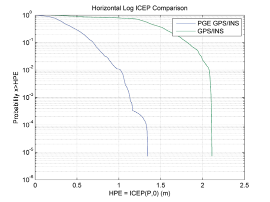
    Couldn’t we detect that high-power RF spoofing signal at the front-end of the GPS receiver? Even if only to tell the on-board systems that there could be hazardous misleading information about? Or run separate GPS and GPS/inertial position solutions, detect significant divergence, and set the same warning flag? And multi-constellation, multi-frequency receivers, and even controlled radiation pattern antennas — all things to investigate.  More work for the aviation receiver guys who labor tirelessly to improve GNSS integrity.

    Of course if you hijack a UAV with a high-power spoofer, you are also spoofing civil transports operating in the same airspace, so now there is the potential to trigger a Federal investigation. It will probably be easier to detect this stuff with moving airborne sensors rather than the fixed ground equipment used to find jammers on trucks at Newark airport, and lots of pilots likely providing real-time location information on radios if their GPS goes even a little haywire. All would help to quickly locate and shut down any spoofer. Nevertheless, it’s a threat to be mitigated.

    Fatal Crash. In South Korea, the effects of intermittent North Korean jamming of GPS to disrupt seal, land, and air navigation in the South may have contributed to the recent fatal crash of a Schiebel Camcopter S-100 drone, a 150-kilogram rotorcraft capable of 220 km/h flight. It should have coped with loss of GPS as the Camcopter has multiple inertial measurement units that allow safe operation and recovery in the absence of GPS signals. Emergency procedures to ensure a safe recovery in such a situation do not appear to have been correctly and adequately followed, manufacturer Schiebel alleges.

    NovAtel may have found one way to help mitigate spoofing on UAVs; the company released a combined civil/SAASM GPS receiver, the OEM625S, aimed specifically at UAVs. Granted, the idea is to add SAASM anti-spoofing capability to a number of UAVs which currently use NovAtel commercial receivers, mostly in military systems. That may be motivated by the desire to avoid further Iranian incidents!

    BAE Systems has been thinking of giving GPS a back-up for just those situations where jamming or even spoofing is detected. BAE’s Navigation via Signals of Opportunity (NAVSOP) system was just announced at the Farnborough air show in the UK and is still in research phase, but looks extremely promising. It interrogates the radio environment for the ID and signal strength of local digital TV and radio signals, plus air traffic control radars, with finer grained adjustments coming from cellphone masts and Wi-Fi routers. Mapping the location of all these sources might be quite an undertaking, and given that these are all non-safety-of-life commercial signals, the sources are subject to the vagaries of power outages, regular maintenance, and breakdowns. Nevertheless, with such a multitude of signals, NAVSOP could well turn out to be a viable back-up for GNSS.

    So, shared access to civil airspace, wider applications in commercial operations, and changes in equipment qualification, along with potential solutions for GNSS jamming and spoofing: lots to consider for the UAS industry.


    Taking It to the House

    U.S. House of Representatives Committee on Homeland Security; Subcommittee on Oversight, Investigations, and Management; Hearing, July 19, 2012:  Using Unmanned Aerial Systems Within the Homeland: Security Game Changer?

    Testimony by Todd E. Humphreys, Ph.D.; Assistant Professor, Cockrell School of Engineering, The University of Texas at Austin. [Excerpted. Prof. Humphreys is a co-author of the article “Drone Hack” in the August issue of GPS World.]

    The vulnerability of civil GPS to spoofing has serious implications for civil unmanned aerial vehicles (UAVs), as was recently illustrated by a dramatic remote hijacking of a UAV at White Sands Missile Range.

    Hacking a UAV by GPS spoofing is but one expression of a larger problem: insecure civil GPS technology has over the last two decades been absorbed deeply into critical systems within our national infrastructure. Besides UAVs, civil GPS spoofing also presents a danger to manned aircraft, maritime craft, communications systems, banking and finance institutions, and the national power grid.

    Constructing from scratch a sophisticated GPS spoofer like the one developed by the University of Texas is not easy. It is not within the capability of the average person on the street, or even the average Anonymous hacker. But the emerging tools of software-defined radio and the availability of GPS signal simulators are putting spoofers within reach of ordinary malefactors.

    There is no quick, easy, and cheap fix for the civil GPS spoofing problem. What is more, not even the most effective GPS spoofing defenses are foolproof. But reasonable, cost-effective spoofing defenses exist which, if implemented, will make successful spoofing much harder.

    I recommend that for non-recreational operation in the national airspace civil UAVs exceeding 18 lbs be required to employ navigation systems that are spoof-resistant.

    More broadly, I recommend that GPS-based timing or navigation systems having a non-trivial role in systems designated by DHS as national critical infrastructure be required to be spoof-resistant.

    Finally, I recommend that the DHS commit to funding development and implementation of a cryptographic authentication signature in one of the existing or forthcoming civil GPS signals.

    Complete testimony (PDF) covers:

    • The potential vulnerabilities of U.S. national transportation, communications, banking and finance, and energy distribution infrastructure;
    • What does it take to build a spoofer? Buy a spoofer?
    • Range and required knowledge of target.
    • Fixing the problem:

    •    Jamming-to-noise sensing defense;
    •    Defense based on SSSC or NMA on WAAS signals;
    •    Multi-system multi-grequency defense;
    •    Single-antenna defense;
    •    Defense based on spread-spectrum security codes on L1C;
    •    Defense based on navigation message authentication on L1C, L2C, or L5;
    •    Correlation prole anomaly defense;
    •    Multi-antenna defense;
    •    Defense based on cross-correlation with military signals.

  • NovAtel SAASM to See First Action in Aerial Drones

    The new OEM625S Selective Availability Anti-Spoofing Module (SAASM) GNSS receiver from NovAtel, launched in a cooperative effort with SAASM expert L-3 Interstate Electronics Corporation (IEC), will get its first applications in the unmanned aerial vehicle (UAV) sector. NovAtel has brought forth the new product in part to meet requirements of UAV manufacturers who are now mandated to have SAASM onboard as well, for in-theater operations in areas of military activity.

    “The new SAASM regulations meant that integrators were looking at having to incorporate another receiver alongside their NovAtel unit, complicating user interface factors and increasing onboard space requirements,” said NovAtel Product Manager Neil Gerein. “The OEM625S gives our customers a drop-in form factor that easily replaces their existing NovAtel OEM receiver.”

    “NovAtel has supplied UAV integrators on the civil scientific side almost since our inception,” Gerein said, adding, “the military has become more and more involved in this market in recent years for budget and various other strategic reasons.” He mentioned that in its 20-year history selling GPS products, for the last 17 years NovAtel has provided receivers and expertise to U.S. and Canada defense contractors, and to defense research labs in Allied countries. Antcom, a wholly-owned NovAtel subsidiary specializing in antennas and microwave products, makes the majority of its sales into military areas.

    Examples of such products in this area — not necessarily from NovAtel customers, who remain unidentified — include hand-launched mini-UAVs like the Aerovironment RQ-11 Raven and Elbit Skylark I, and runway-capable tactical UAVs such as Textron RQ-7 Shadow, Aeronautics DS Aerostar, IAI Searcher II, and InSitu’s ScanEagle UAV system, quickly evolving into a mainstay with the U.S. Navy and its allies thanks to a partnership with Boeing.

    The InSitu ScanEagle was first developed to track dolphins and tuna from fishing boats, to ensure that fish labeled “dolphin-safe” actually are so. The same characteristics needed by commercial fishing boats — low infrastructure launch and recovery, small size, 20-hour long endurance, automated flight patterns — are key for naval operations from larger vessels, and for battlefield surveillance.

    At present the OEM625S, combining a commercial dual-frequency NovAtel GNSS receiver with an L-3 IEC XFACTOR SAASM, provides single-point positioning with SAASM for authorized defense customers. The SAASM position is provided via a dedicated communication port, as well as through NovAtel’s software command protocol, allowing for maximum flexibility. The small form factor and low power consumption expands range of potential defense applications requiring robust SAASM GPS positioning.

    The OEM625S measures 60 x 100 x 9.1 millimeters, and runs on field-upgradeable software. NovAtel will accept orders for the OEM625S from authorized customers starting in Q3 2012.

  • Unmanned Air Systems: Precision Navigation for Critical Operations

    Brown-Fig1 . By Alison K. Brown, Dien Nguyen, and Paige Felker, NAVSYS Corporation, Glenn Colby and Frank Allen, PMA-268 NAVAIR
    Figure 1. Autonomous air refuleing operational view.

    By Alison K. Brown, Dien Nguyen, and Paige Felker, NAVSYS Corporation, Glenn Colby and Frank Allen, PMA-268 NAVAIR

    An alternative precision GPS architecture, Precision RELNAV, enables an airborne tanker plane and a Navy unmanned combat aircraft to navigate independently to a high degree of precision without requiring carrier-cycle ambiguity resolution using precision GPS ephemeris updates to a tightly coupled GPS/inertial solution onboard each aircraft. The solution rivals that of conventional relative kinematic techniques while providing more robust positioning that reduces message traffic between aircraft and does not require a long filtering time.


    Naval Unmanned Combat Air System (N-UCAS) is the U.S. Navy’s program to demonstrate technologies and reduce risk for unmanned, carrier based strike and surveillance aircraft. The Unmanned Combat Air System Carrier Demonstration (UCAS-D) program is specifically maturing technologies for unmanned carrier operations and Autonomous Aerial Refueling (AAR). Successful demonstration of UCAS-D technologies provides for transition and risk reduction to future unmanned and manned programs.

    A key enabler for N-UCAS is the ability to perform AAR so that the N-UCAS can support long duration missions. As shown in Figure 1, the intent is for AAR operations to mirror current manned Aerial Refueling operations as much as possible and to operate using existing Navy probe and drogue and US Air Force boom receptacle refueling methods.

    The planned refueling architecture for probe and drogue and boom-receptacle refueling developed by PMA-268 is shown in Figure 2 and Figure 3. For both of these architectures, the GPS/inertial navigation system on the UAS and tanker are used to calculate a precise relative position to be used by the UAS to approach the tanker from astern. For drogue systems, the final connection to the basket is performed using aiding from a laser-based drogue positioning system. In addition, an optional machine vision system is used to aid both methods of refueling from the receiver. Under the UCAS-D demonstration program testing is being conducted with surrogate aircraft to verify the CONOPS procedures and performance of the precision GPS/inertial navigation solution alternatives being evaluated. NAVSYS is supporting this program through a Small Business Innovation Research (SBIR) contract and is demonstrating a Precision-RELNAV (P-RELNAV) tightly coupled GPS/inertial solution that improves the robustness of the relative navigation solution as described in the following sections.

     Figure 2. Probe and drogue refueling architecture. By Alison K. Brown, Dien Nguyen, and Paige Felker, NAVSYS Corporation, Glenn Colby and Frank Allen, PMA-268 NAVAIR
    Figure 2. Probe and drogue refueling architecture.
     Figure 3. Boom receptacle refuleing architecture. By Alison K. Brown, Dien Nguyen, and Paige Felker, NAVSYS Corporation, Glenn Colby and Frank Allen, PMA-268 NAVAIR
    Figure 3. Boom receptacle refuleing architecture

    Precision RELNAV Algorithm

    The first method that PMA-268 implemented for computing a relative GPS solution used the GPS/inertial integration approach illustrated in Figure 4. The inertial navigation solution from both aircraft was used to calculate the relative inertial vector e that is used for the real-time AAR guidance. The tanker’s raw GPS observations are also passed over the data link to the UAS where a relative kinematic solution is calculated to derive the carrier-phase based relative position between the aircraft, a. This approach relies on solving for the integer carrier cycle ambiguities on the observations from the two aircraft using the same algorithms that were previously developed for use in performing GPS precision approach and landings on the carrier. The precise GPS relative position is then applied to calibrate the inertial derived relative position and the resulting GPS/inertial solution is used to calculate an offset to the center of the refueling envelope (u) for guidance of the UAS to connect to the receptacle.

     Figure 4. Precision-GPS relative GPS positioning. By Alison K. Brown, Dien Nguyen, and Paige Felker, NAVSYS Corporation, Glenn Colby and Frank Allen, PMA-268 NAVAIR
    Figure 4. Precision-GPS relative GPS positioning.

    With the P-RELNAV approach shown in Figure 5, Precision GPS Ephemeris data is provided to both aircraft across the tactical data links using the NAMATH system. As shown in Figure 6, NAMATH provides global services across military tactical data links through the Joint Range Extension (JRE) to provide real-time corrections to the GPS system errors using Zero-Age Precision GPS Ephemeris data, which is refreshed by the GPS Control Segment every 15 minutes. The NAMATH system is currently being used operationally by the U.S. military to improve navigation accuracy and also precision weapons delivery.

    Brown-Fig5 . By Alison K. Brown, Dien Nguyen, and Paige Felker, NAVSYS Corporation, Glenn Colby and Frank Allen, PMA-268 NAVAIR
    Figure 5. Tightly-coupled P-RELNAV Solution.

    Brown-Fig6 .By Alison K. Brown, Dien Nguyen, and Paige Felker, NAVSYS Corporation, Glenn Colby and Frank Allen, PMA-268 NAVAIR
    Figure 6. NAMATH Precision Ephemeris Delivery.

    Using the PGE corrections significantly reduces the errors on the GPS observations allowing the GPS/inertial solution to rapidly converge and not exhibit step changes during satellite transitions from the GPS system bias errors. The GPS/inertial Kalman Filter on the tanker is used to observe the residual errors from the GPS satellites being tracked, and these residuals (δf) are sent from the tanker to the UAS which applies these as an update to its internal GPS/inertial Kalman Filter. As shown below, this final correction sets both the tanker and the UAS on a precise common reference frame resulting in a high accuracy relative position being derived from the vector difference of the two tightly-coupled GPS/inertial solutions (e*).

    Figure 7 shows the difference in the GPS position that is calculated using the Precision GPS Ephemeris as opposed to the Broadcast Ephemeris. This shows that over a month, there can be peak position excursions as high as 5 meters in the horizontal and 10 meters in the vertical based on the GPS broadcast ephemeris. With a GPS/inertial solution, these bias offsets will cause the solution to “trend” between different position bias offsets whenever the satellite selected set changes. This trending introduces significant errors into the relative inertial vector between two aircraft (e).

    Brown-Fig7A . By Alison K. Brown, Dien Nguyen, and Paige Felker, NAVSYS Corporation, Glenn Colby and Frank Allen, PMA-268 NAVAIR

    Brown-Fig7B .By Alison K. Brown, Dien Nguyen, and Paige Felker, NAVSYS Corporation, Glenn Colby and Frank Allen, PMA-268 NAVAIR
    Figure 7. GPS Peak Position Errors from Broadcast Ephemeris Offsets (March 2010).

    P-RELNAV Flight Test Set-Up

    The P-RELNAV performance was tested using data collected on a UH-1 helicopter at Eglin AFB. Two independent GPS/inertial systems were mounted on the equipment plate below the aircraft (Figure 8) and a GPS reference receiver on the ground was used to calculate a kinematic position post-test using a Magellan ZXW receiver on the aircraft as a truth system. The PGE corrections were uplinked to the aircraft through EPLRS for use in calculating a PGE-corrected navigation solution. NAVSYS used recorded GPS and inertial data from a Kearfott KN4073 and a NovAtel/LN-200 inertial system provided by Dahlgren NSWC. The raw GPS (Pseudo-range and carrier phase) and IMU (high rate acceleration and angular rate) data was processed using our InterNav solution and also recorded for post-processing. This data was then played back through InterNav to calculate independent GPS/inertial tightly coupled solutions from the two inertial systems with and without the PGE corrections and to compare the performance of the absolute and relative solutions against the kinematic positioning truth data.

     Figure 8. Flight test equipment. By Alison K. Brown, Dien Nguyen, and Paige Felker, NAVSYS Corporation, Glenn Colby and Frank Allen, PMA-268 NAVAIR
    Figure 8. Flight test equipment.

    P-RELNAV Flight Test Results

    The P-RELNAV algorithms were implemented in our InterNav software package. This has been previously used to generate very high accuracy relative kinematic solutions for providing high-rate Time Space Position Information (TSPI) for instrumenting F-16 aircraft. The InterNav software was upgraded to apply the tightly-coupled GPS updates to the inertial solution using the PGE Zero-Age Differential GPS (ZDGPS) corrections, and also to apply the GPS residual updates (δf) in the UAS Kalman Filter to compute the P-RELNAV relative position solution.

    Dual-frequency observations from the GPS receivers were used to correct for the ionospheric group delays in the solution.

    The performance of the P-RELNAV solution was evaluated by comparing the results from the two independent inertial solutions for the same location on the UH-1 aircraft. Tests were conducted over multiple flights with the GPS antennas at different locations on the UH-1.

    The results from the first flight test are shown in Figure 9 through Figure 13. Figure 9 shows the GPS/inertial results during the flight with a tightly-coupled solution but without PGE corrections. Figure 10 shows the GPS/inertial results during the flight with a tightly-coupled solution but with PGE enabled. Figure 11 shows the satellite visibility during the flight test. These plots show that the satellite geometry changes, dramatically affecting the inertial position covariance, whenever the satellites used in the solution change. The inertial filters these errors, but the relative solution is biased and drifts resulting in over 2 meter errors. In Figure 12 the same plot is shown when the PGE corrections are applied. This shows that the relative position error has been reduced to better than 1 m per axis and 35 cm 1-sigma. For flight critical operations, such as AAR, minimizing position excursions is essential. Figure 13 and Figure 14 show a statistical measure of the percentage of time that the data exceeds a horizontal or vertical threshold. This shows the benefit of the PGE corrections in removing GPS excursions caused by satellite ephemeris errors from the navigation solution. (See the Appendix for a definition of the Inverse Circular Error Probable (ICEP) metric and its comparison with other statistical measures).

     Figure 9. Flight 1: Relative position of KN and NovAtel/LN200 GPS/INS solutions. By Alison K. Brown, Dien Nguyen, and Paige Felker, NAVSYS Corporation, Glenn Colby and Frank Allen, PMA-268 NAVAIR
    Figure 9. Flight 1: Relative position of KN and NovAtel/LN200 GPS/INS solutions.
     Figure 10. Flight 1: Relative position of KN and NovAtel/LN200 PGE enabled GPS/INS solutions. By Alison K. Brown, Dien Nguyen, and Paige Felker, NAVSYS Corporation, Glenn Colby and Frank Allen, PMA-268 NAVAIR
    Figure 10. Flight 1: Relative position of KN and NovAtel/LN200 PGE enabled GPS/INS solutions.
     Figure 11. Flight 1: Valid PRNs used in KN GPS/INS solution. By Alison K. Brown, Dien Nguyen, and Paige Felker, NAVSYS Corporation, Glenn Colby and Frank Allen, PMA-268 NAVAIR
    Figure 11. Flight 1: Valid PRNs used in KN GPS/INS solution.
     Figure 12. Flight 1: Relative Position of KN and NovAtel/LN200 PGE enabled GPS/INS solutions. By Alison K. Brown, Dien Nguyen, and Paige Felker, NAVSYS Corporation, Glenn Colby and Frank Allen, PMA-268 NAVAIR
    Figure 12. Flight 1: Relative Position of KN and NovAtel/LN200 PGE enabled GPS/INS solutions.
     Figure 13. Flight 1: Horizontal ICEP comparison for PGE enabled GPS/INS and GPS/INS solutions. By Alison K. Brown, Dien Nguyen, and Paige Felker, NAVSYS Corporation, Glenn Colby and Frank Allen, PMA-268 NAVAIR
    Figure 13. Flight 1: Horizontal ICEP comparison for PGE enabled GPS/INS and GPS/INS solutions.
     Figure 14. Flight 1: Vertical ICEP comparison for PGE enabled GPS/INS and GPS/INS solutions. By Alison K. Brown, Dien Nguyen, and Paige Felker, NAVSYS Corporation, Glenn Colby and Frank Allen, PMA-268 NAVAIR
    Figure 14. Flight 1: Vertical ICEP comparison for PGE enabled GPS/INS and GPS/INS solutions.

    Since both GPS receivers used in the test had a reasonably clear view of the sky, they were both tracking the same satellites. In the AAR CONOPS, the UAS approaches the tanker from below and so will have some satellites obscured from view by the tanker (see Figure 4). In this case, the use of different satellites can significantly increase the relative position error when PGE corrections are not available. In the case shown where one satellite was forced as a drop-out, the non PGE corrected vertical error grew to 4 meters for the relative solution.

    Further improvements in the P-RELNAV performance will be achieved using the residual (δf) update mode in the InterNav Kalman Filter to set the estimated observation residuals for the common satellites to the same values for the UAS and Tanker GPS/inertial filters. This mode is currently being tested and the results will be presented in a follow-on paper.

     Figure 15. Flight 1: Horizontal ICEP plot for PGE enabled GPS/INS and GPS/INS solutions. Different satellites tracked by the receivers. By Alison K. Brown, Dien Nguyen, and Paige Felker, NAVSYS Corporation, Glenn Colby and Frank Allen, PMA-268 NAVAIR
    Figure 15. Flight 1: Horizontal ICEP plot for PGE enabled GPS/INS and GPS/INS solutions. Different satellites tracked by the receivers.
     Figure 16. Flight 1: Vertical ICEP comparison for PGE enabled GPS/INS and GPS/INS solutions. Different satellites tracked by the receivers. By Alison K. Brown, Dien Nguyen, and Paige Felker, NAVSYS Corporation, Glenn Colby and Frank Allen, PMA-268 NAVAIR
    Figure 16. Flight 1: Vertical ICEP comparison for PGE enabled GPS/INS and GPS/INS solutions. Different satellites tracked by the receivers.

    Conclusion

    The P-RELNAV solution has the following advantages over using a conventional relative kinematic positioning solution in meeting the Automated Aerial Refueling precision positioning requirements.

    • Fast initialization — does not require time for carrier ambiguity cycles to be resolved.
    • Robust operation during satellite obscuration by the tanker — is not dependent on common satellites being maintained in view between platforms.
    • Insensitive to loss of carrier lock — does not require cycle ambiguity reinitialization if carrier lock is lost during the UAS approach to the tanker.

    Work is proceeding on testing the P-RELNAV solution. Additional test data is being collected for performance evaluation under the UCAS-D demonstration program using dual aircraft as surrogates to demonstrate the P-RELNAV performance and compare the benefits of the P-RELNAV tightly coupled approach with the PGPS kinematic solution.

    This work was sponsored under NAVAIR contract N68335-10-C-0094. The authors gratefully acknowledge the support of PMA-268 and the assistance of NSWC Dahlgren in collecting the flight test data and providing the truth reference for the P-RELNAV analysis.


    Appendix: Inverse Circular Error Probable (ICEP)

    For safety-of-life applications, the statistic of the excursion events, for example when a horizontal error is outside the safe error bound, is often more important than the knowledge of the percentage of points that are within a smaller error bound, such as CEP or DRMS. These excursion, or low probability, statistics can be examined with the Inverse Circular Error Probability (ICEP) function. The ICEP provides the horizontal position error (HPE) with a specified probability that a result could be outside this value. An optional input to the function is a filtering time constant, with the filter applied to the time-series horizontal error data before calculating the ICEP. This separates the effect of bias errors from short term noise errors that could be filtered (for example with an inertial unit) from the HPE.

    HPE = ICEP (P%, τ)

    Where
    HPE= Horizontal Position Error value [m]
    P% = Percent of total horizontal errors (x) that are larger than HPE
    τ = filter time constant to reduce short term white noise

    Note that the Circular Error Probable (CEP) which is the radial value that encloses 50% of the positioning results is closely related to ICEP, with
    CEP = ICEP(50%, 0)

    Also the R95 which is the radial value that encloses 95% of the positioning results is related to ICEP, with
    R95=ICEP(5%,0)

    Other common statistics used are the DRMS and 2DRMS values which are defined below, are also related to ICEP through the following equations.

    Screen shot 2013-01-04 at 7.57.08 PM . By Alison K. Brown, Dien Nguyen, and Paige Felker, NAVSYS Corporation, Glenn Colby and Frank Allen, PMA-268 NAVAIR

    For a Gaussian, uncorrelated error distributions with sigma of one meter in the range and azimuth axes, the ICEP is shown in Figure A-1 in blue. For each horizontal position error value, the ICEP gives the percentage of the distribution that has larger errors. Also shown on this plot are the CEP, DRMS, 2DRMS and R95 values which match the 1-sigma scale factors shown in the table above. Figure A-2 is the same data with a log10 plot. In this plot the y-axis is probability rather than percent. This plot is useful for examination of outlier behavior, as it shows low probability events more clearly.

    Brown-FigA1 . By Alison K. Brown, Dien Nguyen, and Paige Felker, NAVSYS Corporation, Glenn Colby and Frank Allen, PMA-268 NAVAIR
    Figure A-1. ICEP(P,0) for a Gaussian Distribution with 1 m 1-sigma.
     Figure A-2. Log Scale ICEP(P,0) for a Gaussian Distribution with 1 m 1-sigma. By Alison K. Brown, Dien Nguyen, and Paige Felker, NAVSYS Corporation, Glenn Colby and Frank Allen, PMA-268 NAVAIR
    Figure A-2. Log Scale ICEP(P,0) for a Gaussian Distribution with 1 m 1-sigma.

    Screen shot 2013-01-04 at 8.01.11 PM . By Alison K. Brown, Dien Nguyen, and Paige Felker, NAVSYS Corporation, Glenn Colby and Frank Allen, PMA-268 NAVAIR


    Alison Brown is president and chief executive officer of NAVSYS Corporation, which she founded in 1986. NAVSYS Corporation specializes in developing next generation Global Positioning System (GPS) technology. She has a Ph.D. in mechanics, aerospace, and nuclear engineering from UCLA.

    Dien Nguyen works for NAVSYS Corporation as a research engineer specializing in Kalman filtering estimations, kinematic positioning, and related navigational optimization techniques. He holds an M.S. in electrical engineering from Clemson University.

    Paige Felker is a research engineer in the Algorithms and Analysis group at NAVSYS Corporation. She holds an M.S. in aerospace engineering from the University of Texas at Austin.

    Glenn Colby is the chief architect for the Navy Unmanned Combat Air System at the Naval Air Systems Command in Patuxent River, Maryland. He has led the research, development, and testing of advanced aircraft, navigation and communications systems for more than 26 years. He received his B.S. in aerospace engineering with honors at the University of Virginia in 1984.

    Frank Allen is the technology manager for the Navy Unmanned Combat Air System at the Naval Air Systems Command. In the last 16 years he has worked in management of research and development of advanced aircraft navigation and communications systems. Frank received his M.S. in physics from Northeastern University.

  • Nano Hummingbird

    The concept demonstrator has a wingspan of 6.5 inches and weighs just 19 grams – a little less than an AA battery. The bot carries onboard a motor, video camera, network communications and a battery, and the whole thing is housed in a light weight plastic humming bird-esque disguise. Image Credit: AeroVironment, 2011
    The concept demonstrator has a wingspan of 6.5 inches and weighs just 19 grams – a little less than an AA battery. The bot carries onboard a motor, video camera, network communications and a battery, and the whole thing is housed in a light weight plastic humming bird-esque disguise.
    Image Credit: AeroVironment, 2011

    By Art Kalinski, GISP

    U.S. military archives hold 24 million minutes of video collected by Predators and other remotely piloted aircraft that have become an essential tool for commanders. But the library is largely useless because analysts often have no way of knowing exactly what they have, or any way to search for information that is particularly valuable.

    To help solve that problem, the Air Force and government spy satellite experts have begun working with industry experts to adapt the methods that enable the NFL and other broadcasters to quickly find and show replays, display on-field first-down markers and jot John Madden-style notations on the screen.

    “The NFL has the technology so you can pull an instant replay of any Brett Favre touchdown over his career,” said Carl Rhodes, a researcher with RAND Corp. “The idea is maybe the Air Force could use similar technology to look at what has happened at a particular corner in Afghanistan in the past week or past year.”

    Sports television broadcasters mark video with embedded text “tags” that later can be searched to find footage of a particular player or play. Such tags can help editors compile a highlight reel of the day’s most exciting home runs, or a retrospective of the year’s best dunks.

    The military is seeking to use similar technology to track possible insurgents in theaters thousands of miles away.

    Drones are used by the CIA to attack suspected insurgent sites in Pakistan’s tribal areas along the Afghan border. In Afghanistan and Iraq, they are operated by the military, and are used more for spying and observation.

    “We are used to having the cutting-edge technology: reconnaissance satellites and unmanned vehicles,” said Maj. Gen. James Poss, who helps oversee the Air Force’s reconnaissance programs. “And this is the first time industry is really way ahead of us.”

    Unmanned aircraft have been used for reconnaissance since the 1990s. The first armed drones were rushed to Afghanistan with a minimum of testing days after the Sept. 11, 2001, terrorist attacks.

    The military is still refining the aircraft, but more than 7,000 drones of all types are now in use over Afghanistan and Iraq. The Air Force is spending $3 billion a year to buy and operate the aircraft, and is training more pilots to fly unmanned than manned vehicles.

    Pilots can fly them remotely from bases in the U.S., with others in the theater of action handling takeoffs and landings. The pilots are assisted by camera operators — some of them technicians as young as 19 or 20 — and intelligence coordinators.

    They may be called upon to watch over a U.S. military vehicle stranded in the Afghan desert until help arrives, or launch a missile strike. Mistakes can be deadly. Results of a U.S. military investigation released last month criticized a drone crew based in Nevada and ground commanders in Afghanistan for misidentifying civilians as insurgents. Using their information, a helicopter airstrike was authorized. As many as 23 civilians were killed.

    The CIA does not publicly acknowledge the existence of its program in Pakistan, but officials say it received permission two years ago to launch attacks on the basis of “pattern of life” analysis — without knowing the names of its targets. Officials say that they may conduct surveillance for days before deciding they have enough evidence to launch an attack, and that they gather so much detail that they can watch for the routine arrival of particular vehicles or the characteristics of individual people.

    The military once stored Predator video in much the same way it handled photos from a U-2 spy plane or a satellite: It chopped the video into short clips and filed it by date and location.

    But new technologies developed by firms such as Harris and Lockheed Martin record the observations of analysts who monitor the video feeds, creating a database of terms and footage that can later be searched.

    For instance, every time a white truck appears on video, an analyst will type “white truck.” The observation automatically tags that portion of the video. Later, if someone wants to find all the white trucks that passed by a particular building, all they need to do is designate the area of interest and the time frame and search for “white truck.”

    The Air Force hopes that eventually, such emerging technology will automatically give people, places and vehicles more unique identifiers. Then the database will be able to search for specific white trucks, such as one with a dented fender or any other unique mark.

    In addition to improving archives, the new tools also may help analysts combine live video feeds with other sources of intelligence to better understand the situation on the ground.

    Analysts soon may be able to view Predator video feeds alongside intercepted phone calls from the area under surveillance. They also could view area maps or other information.

    “We are creating situational awareness in real time,” said John Delay, a director of strategy for Harris, a defense contractor that also equips broadcasters.

    The drive to change began in earnest four years ago, when Michael O’Neal, a civilian working for the Air Force, went to the National Association of Broadcasters symposium in Las Vegas, a trade show where companies that help the television industry manage video exhibit their products.

    Some businesses thought the military would be too small of a market. Harris, however, showed an interest, and O’Neal began working with the firm’s executives.

    Two years later, Harris had a working version of its technology, the Full-Motion Video Asset Management Engine, or FAME.

    An early version of the system, developed by Lockheed Martin and Harris, is being tested in Afghanistan on a limited number of smaller unmanned planes flown by the Army. The Air Force hopes to do its own tests with larger Predator and Reaper planes.

    It is not known whether the CIA is using the technology yet, but it is likely to eventually employ some version of it. The National Geospatial-Intelligence Agency has established standards for the new archiving technology so that all surveillance video can be easily searched.

    In addition to news and sports technologies, the Air Force has examined video applications used by reality TV. At the request of the Air Force, one RAND Corp. analyst spent time last fall on the set of a reality show to see what lessons the military might glean from its production techniques. The think tank is prohibited from disclosing which show it visited.

    Reality television is of limited usefulness because the setting is a “controlled environment,” said Poss, the Air Force major general. The range of expected actions on a reality show set is far more limited than that of possible insurgents in Afghanistan.

    But it is instructive: Instead of monitoring a single camera that captures a range of images, television editors can use a variety of cameras and angles to track a single subject.

    “In reality TV, there could be 20 cameras. Instead of each person watching a camera in each room, you have a camera following each individual around,” said Rhodes of the RAND Corp. “That doesn’t exactly translate to the Air Force’s job, but there are things they can learn.”

    Read more about it.