Tag: GNSS receiver

  • Signal Decoding with Conventional Receiver and Antenna

    Signal Decoding with Conventional Receiver and Antenna

    A Case History Using the New Galileo E6-B/C Signal

    By Sergei Yudanov, JAVAD GNSS

    A method of decoding an unknown pseudorandom noise code uses a conventional GNSS antenna and receiver with modified firmware. The method was verified using the signals from the Galileo In-Orbit Validation satellites.

    Decoding an unknown GNSS pseudorandom noise (PRN) code can be rather easily done using a high-gain steerable dish antenna as was used, for example, in determine the BeiDou-M1 broadcast codes before they were publicly announced. The signal-to-noise ratio within one chip of the code is sufficient to determine its sign. This article describes a method of getting this information using a conventional GNSS antenna and receiver with modified firmware. The method was verified using the signals from the Galileo In-Orbit Validation (IOV) satellites. In spite of the fact that only pilot signal decoding seems to be possible at first glance, it is shown that in practice data signals can also be decoded.

    Concept

    The idea is to do coherent accumulation of each chip of an unknown signal during a rather long time interval. The interval may be as long as a full satellite pass; for medium Earth orbits, this could be up to six hours. One of the receiver’s channels is configured in the same way as for signal tracking. The I and Q signal components are accumulated during one chip length in the digital signal processor, and these values are added to an array cell, referenced by chip number, by the processor. Only a limited amount of information need be known about the signal: its RF frequency; the expected chip rate; the expected total code length; and the modulation method.

    The decoding of binary-phase-shift-keying (BPSK) signals (as most often used) is the subject of this article. It appears that the decoding of more complicated signals is possible too, but this should be proved. A limitation of this method (in common with that of the dish method) is the maximum total code length that can be handled: for lengths greater than one second and bitrates higher than 10,000 kilobits per second, the receiver’s resources may not be sufficient to deal with the signal.

    Reconstructing the Signal’s Phase

    This method requires coherency. During the full accumulation period, the phase difference between the real signal phase and the phase of the signal generated by the receiver’s channel should be much less than one cycle of the carrier frequency. Depending on the GNSS’s available signals, different approaches may be used. The simplest case is reconstruction of a third signal while two other signals on different frequencies are of known structure and can be tracked.

    The main (and possibly the only significant) disturbing factor is the ionosphere. The ionospheric delay (or, more correctly, the variation of ionospheric delay) is calculated using the two known tracked signals, then the phase of the third signal, as affected by the ionosphere, is predicted.

    The final formula (the calculations are trivial and are widely available in the literature) is:
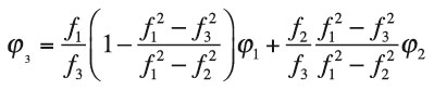
    Y-Eq1

    where:
    φ1 , f1 are the phase and frequency of the first signal in cycles and Hz, respectively
    φ2 , f2   are the phase and frequency of the second signal in cycles and Hz, respectively
    φ3 , f3   are the phase and frequency of the third signal in cycles and Hz, respectively.

    It was confirmed that for all pass periods (elevation angles less than 10 degrees were not tested), the difference between the calculated phase and real phase was always less than one-tenth of a cycle. GPS Block IIF satellites PRN 1 and PRN 25 were used to prove this: the L1 C/A-code and L5 signals were used as the first and second signals, with the L2C signal as the third unknown.

    If two known signals are not available, and the ionospheric delay cannot be precisely calculated, it is theoretically possible to obtain an estimate of the delay from one or more neighboring satellites with two signals available. Calculations and estimations should be carried out to investigate the expected precision.

    The Experiment

    The Galileo E6-B/C signal as currently transmitted by the IOV satellites was selected for the experiment, as its structure has not been published. The E6 signal has three components: E6-A, E6-B and E6-C. The E6-A component is part of the Galileo Public Regulated Service, while the two other components will serve the Galileo Commercial Service. The E6-B component carries a data signal, while the E6-C component is a pilot signal.

    From open sources, it is known that the carrier frequency of the E6 signal is 1278.75 MHz and that the E6-B and E6-C components use BPSK modulation at 5,115 chips per millisecond with a primary code length of one millisecond. E6-B’s data rate is 1,000 bits per second and the total length of the pilot code is 100 milliseconds (a secondary code of 100 bits over 100 milliseconds is also present in the E6-C signal, which aids in signal acquisition).

    A slightly modified commercial high-precision multi-GNSS receiver, with the E6 band and without the GLONASS L2 band, was used for this experiment. The receiver was connected to a conventional GNSS antenna, placed on a roof and was configured as described above. The E1 signal was used as the first signal and E5a as the second signal. The E6 code tracking (using 5,115 chip values of zero) was 100 percent guided from the E1 code tracking (the changing of the code delay in the ionosphere was ignored). The E6 phase was guided from E1 and E5a using the above equation. Two arrays for 511,500 I and Q samples were organized in firmware. The integration period was set to one chip (200 nanoseconds).

    Galileo IOV satellite PRN 11 (also variously known as E11, ProtoFlight Model and GSAT0101) was used initially, and the experiment started when the satellite’s elevation angle was about 60 degrees and lasted for only about 30 minutes. Then the I and Q vectors were downloaded to a PC and analyzed.

    Decoding of Pilot Signal (E6-C)

    Decoding of the pilot signal is made under the assumption that any possible influence of the data signal is small because the number of ones and zeros of E6-B in each of 511,500 chips of the 100-millisecond integration interval is about the same. First, the secondary code was obtained. Figure 1 shows the correlation of the first 5,115 chips with 5,115 chips shifted by 0 to 511,500 chips. Because the initial phase of the E6 signal is unknown, two hypotheses for computing the amplitude or signal level were checked: [A] = [I] + [Q] and [A] = [I] – [Q], and the combination with the higher correlation value was selected for all further analysis.

    Y-Fig1
    Figure 1. Un-normalized autocorrelation of E6-C signal chips.

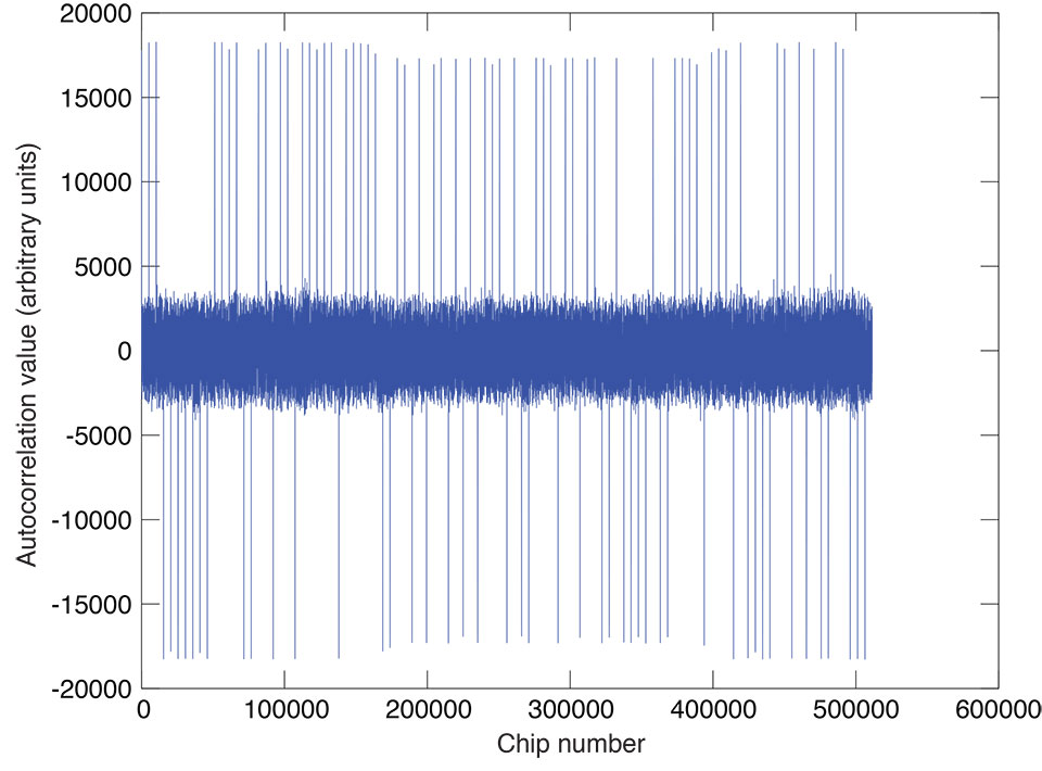
    In Figure 1, the secondary code is highly visible: we see a sequence of 100 positive and negative correlation peaks (11100000001111 …; interpreting the negative peaks as zeros).This code is the exact complement (all bits reversed) of the published E5a pilot secondary code for this satellite. More will be said about the derived codes and their complements later. It appears that, for all of the IOV satellites, the E6-C secondary codes are the same as the E5a secondary codes.

    After obtaining the secondary code, it is possible to coherently add all 100 milliseconds of the integration interval with the secondary code sign to increase the energy in each chip by 100 times. Proceeding, we now have 5,115 chips of the pilot signal ­— the E6-C primary code.

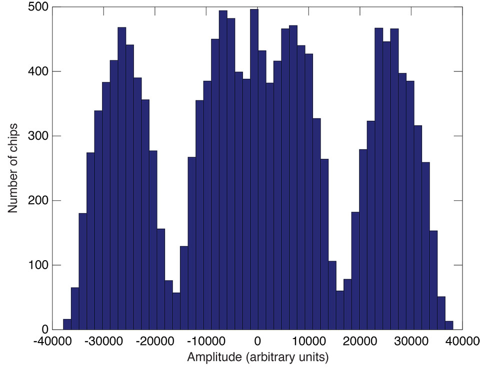
    To understand the correctness of the procedure and to check its results, we need to confirm that there is enough signal energy in each chip. To this end, a histogram of the pilot signal chip amplitudes can be plotted (see Figure 2). We see that there is nothing in the middle of the plot. This means that all 5,115 chips are correct, and there is no chance that even one bit is wrong.

    Y-Fig2
    Figure 2. Histogram of pilot signal chip amplitude in arbitrary units.

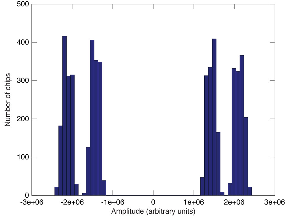
    But there is one effect that seems strange at first glance: instead of two peaks we have four (two near each other). We will shortly see that this phenomenon results from the influence of the E6-B data signal and it may be decoded also.

    Decoding the Data Signal

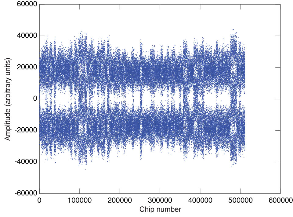
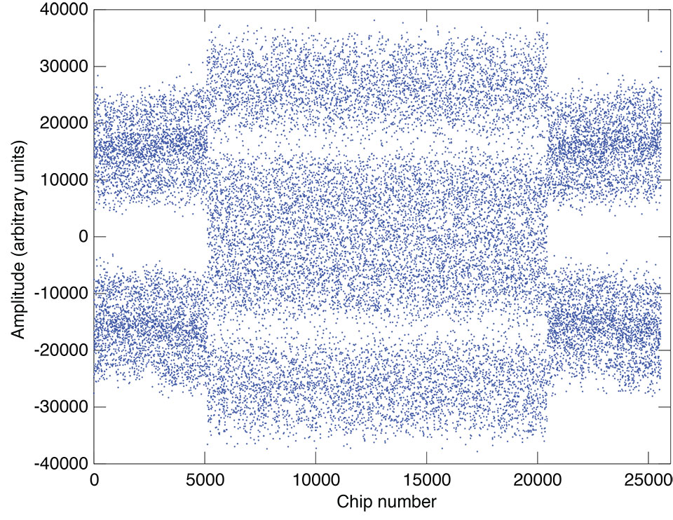
    The presence of four peaks in the histogram of Figure 2 was not understood initially, so a plot of all 511,500 signal code chips was made (see Figure 3).
    Interestingly, each millisecond of the signal has its own distribution, and milliseconds can be found where the distribution is close to that when two signals with the same chip rate are present. In this case, there should be three peaks in the energy (signal strength) spectrum: –2E, 0, and +2E, where E is the energy of one signal (assuming the B and C signals have the same strength).

    Figure 3. Plot of 511,500 signal code chip amplitudes in arbitrary units.
    Figure 3. Plot of 511,500 signal code chip amplitudes in arbitrary units.

    One such time interval (starting at millisecond 92 and ending at millisecond 97) is shown in Figure 4. The middle of the plot (milliseconds 93 to 96) shows the described behavior. Figure 5 is a histogram of signal code chip amplitude for the signal from milliseconds 93 to 96.

    Figure 4  Plot of signal code chip amplitude in arbitrary units from milliseconds 93 to 96.
    Figure 4. Plot of signal code chip amplitude in arbitrary units from milliseconds 93 to 96.

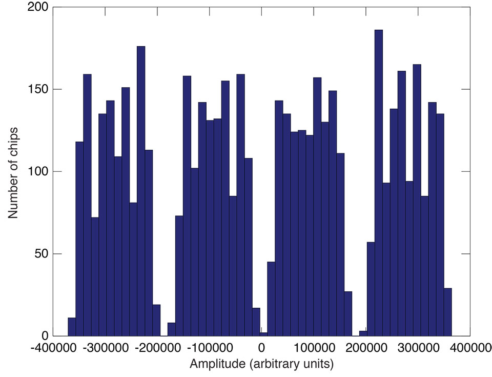
    Then we collect all such samples (milliseconds) with the same data sign together to increase the signal level. Finally, 5,115 values are obtained. Their distribution is shown in Figure 6.

    The central peak is divided into two peaks (because of the presence of the pilot signal), but a gap between the central and side peaks (unlike the case of Figure 5) is achieved. This allows us to get the correct sign of all data signal chips. Subtracting the already known pilot signal chips, we get the 5,115 chips of the data signal — the E6-B primary code. This method works when there are at least some samples (milliseconds) where the number of chips with the same data bit in the data signal is significantly more than half.

    Y-Fig5
    Figure 5. Histogram of signal code chip amplitude.
    Figure 6  Histogram of the signed sum of milliseconds chip amplitude with a noticeable presence of the data signal.
    Figure 6. Histogram of the signed sum of milliseconds chip amplitude with a noticeable presence of the data signal.
    Proving the Codes

    The experimentally determined E6-B and E6-C primary codes and the E6-C secondary codes for all four IOVsatellites (PRNs 11, 12, 19, and 20) were put in the receiver firmware. The receiver was then able to autonomously track the E6-B and E6-C signals of the satellites.

    Initial decoding of E6-B navigation data has been performed. It appears that the data has the same preamble (the 16-bit synchronization word) as that given for the E6-B signal in the GIOVE Interface Control Document (ICD). Convolutional encoding for forward error correction is applied as described in the Galileo Open Service ICD, and 24-bit cyclic redundancy check error detection (CRC-24) is used. At the time of the analysis, all four IOV satellites transmitted the same constant navigation data message.

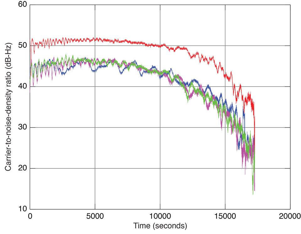
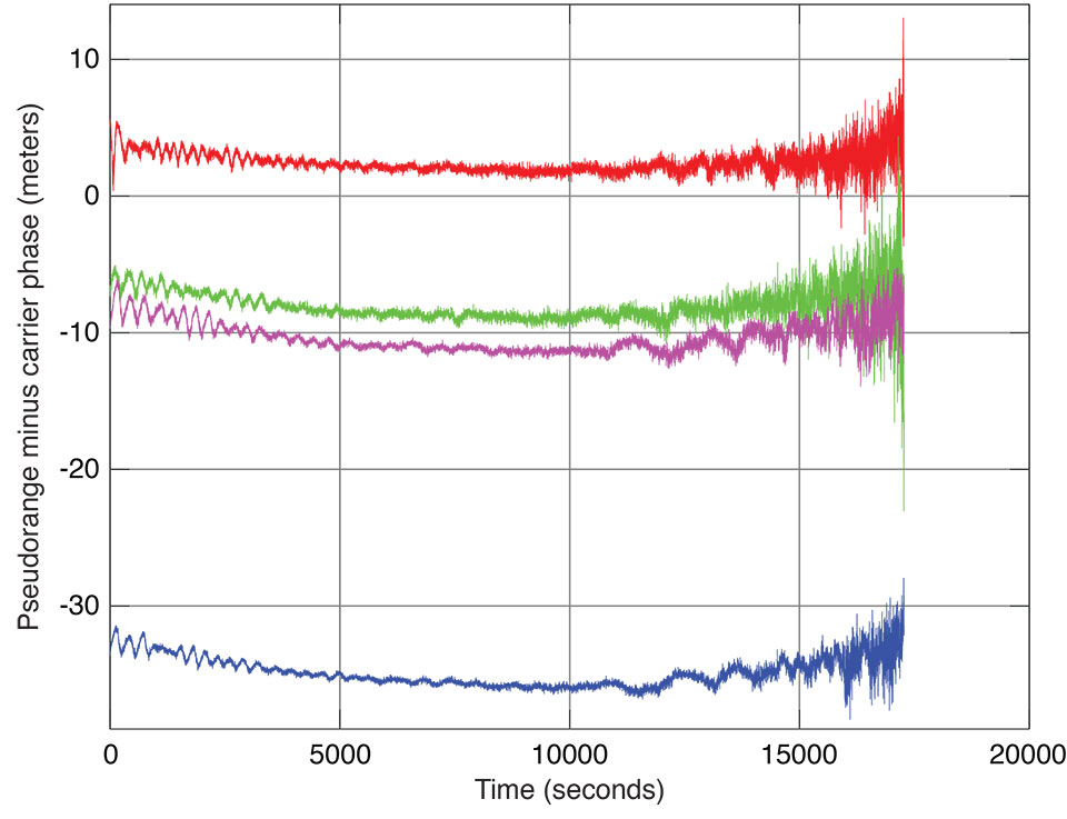
    Plots of PRN 11 E6 signal tracking are shown in Figure 7 and in Figure 8. The determined codes may be found at env-gpsworld-integration.kinsta.cloud/galileo-E6-codes. Some of these codes may be the exact complement of the official codes since the code-determination technique has a one-half cycle carrier-phase ambiguity resulting in an initial chip value ambiguity. But from the point of view of receiver tracking, this is immaterial.

    Figure 7  Signal-to-noise-density ratio of E1 (red), E5a (magenta), E5b (blue), and E6 (green) code tracking of Galileo IOV satellite PRN 11 on December 21–22, 2012.
    Figure 7. Signal-to-noise-density ratio of E1 (red), E5a (magenta), E5b (blue), and E6 (green) code tracking of Galileo IOV satellite PRN 11 on December 21–22, 2012.
    Figure 8  Pseudorange minus carrier phase (in units of meters) of E1 (red), E5a (magenta), E5b (blue), and E6 (green) code tracking of Galileo IOV satellite PRN 11 on December 21–22, 2012.
    Figure 8. Pseudorange minus carrier phase (in units of meters) of E1 (red), E5a (magenta), E5b (blue), and E6 (green) code tracking of Galileo IOV satellite PRN 11 on December 21–22, 2012.
    Acknowledgments

    Special thanks to JAVAD GNSS’s DSP system developers. The system is flexible so it allows us to do tricks like setting the integration period to one chip, and powerful enough to be able to do required jobs within a 200-nanosecond cycle. This article was prepared for publication by Richard Langley.

    Manufacturers

    A JAVAD GNSS TRE-G3T-E OEM receiver, a modification of the TRE-G3T receiver, was used in the experiment, connected to a conventional JAVAD GNSS antenna. Plots of E6 code tracking of all four IOV satellites may be found on the company’s website.


    Sergei Yudanov is a senior firmware developer at JAVAD GNSS, Moscow.

  • u-blox Demonstrates Navigation Using BeiDou

    Swiss-based u‑blox, a provider of GPS/GNSS and wireless semiconductors, has achieved successful satellite positioning using China’s BeiDou Navigation Satellite System. According to u-blox, the technical achievement establishes u-blox as the first GNSS component vendor to demonstrate compatibility with all globally deployed positioning systems: GPS, GLONASS, Galileo, QZSS and now BeiDou.

    However, NovAtel has also announced support for the BeiDou Navigation Satellite System on its OEM6 family and select OEMStar GNSS receivers.

    Customer demonstration of the u-blox technology will begin during Q1 2013.

    “We are thrilled to have achieved this milestone only three weeks after the BeiDou specification was published,” said Thomas Seiler, u-blox CEO. “China will become the world’s most important single market for devices relying on embedded satellite navigation, and u-blox plans to be a major player in this market.”

    BeiDou-2 currently has 15 satellites in orbit, offering navigation and positioning services to users in China and Southeast Asia. It will ultimately consist of 35 satellites providing worldwide positioning capability over its open service to within 10 meters accuracy.

    u-blox will be demonstrating BeiDou compatibility with their latest GNSS platform at embeddedworld 2013 February 26-28 in Nuremberg, Germany, stand 4A-325.

  • NovAtel GNSS Receivers Provide BeiDou Support

    NovAtel announces support for the BeiDou Navigation Satellite System on its OEM6 family and select OEMStar GNSS receivers.

    The long-anticipated BeiDou Navigation Satellite System (BDS) Interface Control Document (ICD) release is a significant milestone that facilitates global acceptance of BeiDou into the growing range of satellite-based positioning applications, NovAtel said.

    NovAtel has a long-standing partnership with several Chinese GNSS system manufacturers. This partnership has allowed NovAtel to verify B1 and B2 signal tracking on its latest generation receivers. The company has been supplying GNSS receivers that include the BeiDou constellation since Q4 2010.

    “We are excited to see what performance improvements BeiDou will provide to our AdVance RTK, GL1DE and SPAN GNSS/INS positioning algorithms,” said Pat Fenton, NovAtel CTO.

    BeiDou positioning has been available through NovAtel’s Chinese partners utilizing the receiver Application Programming Interface (API) feature. With the BeiDou ICD made available to the public, NovAtel is now able to offer BeiDou positioning on its receiver products directly.

    Firmware updates for the OEM6 and OEMStar receivers will enable tracking of the BeiDou signal in conjunction with GPS, GLONASS, Galileo and QZSS signals that are currently supported. Over the coming months NovAtel will be working with early-adopter customers to optimize their receiver positioning engines to support the BeiDou signals.

    Customers interested in trialing BeiDou functionality on their receivers should contact NovAtel Customer Support at [email protected].

  • Leica Geosystems Introduces Viva GS14 GNSS Receiver

    Leica Viva SmartStation GS14

    Leica Geosystems has announced the release of the Leica Viva GS14 GNSS receiver. The GS14 is designed to be the best-price performance GNSS receiver in its class. The built-in GSM and UHF radio, internal memory and IP68 protection fully equips a user for nearly any measuring task, providing a reliable, revenue-generating production unit, the company said.

    When combined with the Leica Viva GNSS RTK, the GS14 creates a tightly integrated GNSS system ensuring the highest degree of flexibility, quality and reliability, Leica Geosystems said.

    The compact Leica Viva GS14 offers comfort in the field and a variety of setups and operating options, the company said. The Viva GS14 can be used as a light-weight rover and as a base station. The Leica Viva GS14 further enhances the Leica Viva series by offering a complete range of GNSS and total station solutions combining precision with maximum versatility. Users gain speed and efficiency by reducing the number of setups and control points with the unique SmartStation, and the versatile SmartPole allows instant switching between GNSS and TPS with a simple icon tap, Leica Geosystems said. The system exceeds specifications going beyond industrial standards. Moreover, the temperature range from -40°C to +65 °C ensures a flawless performance even in most challenging working environments.

    With  Leica Geosystems’ SmartTrack and SmartCheck technology integrated, the Leica Viva GS14 tracks signals with the highest quality and constantly evaluates and verifies the RTK solution to ensure the most reliable RTK positions. Together with the innovative Leica xRTK technology, positions are delivered in difficult GNSS environments. The Leica Viva GS14 also is ready for future satellite signals.

    The Leica Viva GS14 is available this month. Ordering information can be obtained from authorized Leica Geosystems representative.

  • NVS Technologies Selected by Alberding for Sub-Meter GNSS Receiver

    Alberding GmbH, a  developer and distributor of professional GNSS system solutions, has recently announced the Alberding A07 personal navigator, featuring NVS Technologies AG’s NV08C-CSM high-performance multi-GNSS constellation receiver. The Alberding A07 is a low-cost single frequency GNSS receiver designed for personal navigation and other sub-meter accuracy positioning applications in an urban environment.

    The device integrates NVS Technologies’ NV08C-CSM multi-constellation (GPS, GLONASS, Galileo, COMPASS and SBAS) L1 receiver with GPRS and Bluetooth communication modules, an RFID reader, and a processor. The Alberding A07 comes with an integrated GNSS antenna, but for monitoring and tracking applications, it is also available with an external antenna.

    Applications include:

    • Pedestrian navigation and tracking
    • Navigation for the visually impaired
    • RFID based indoor positioning
    • Transportation
    • GIS data collection
    • Displacement monitoring and alarming

    The Alberding DGNSS processing algorithm and Kalman filter take raw GNSS observation data to compute a highly accurate position solution in real time. Position information can then be transmitted via Bluetooth to custom specific applications running on devices such as smartphones. As an example, the Alberding A07 can assist blind or visually impaired people with orientation and navigation on the streets.

  • Geneq Introduces Palm-Sized GPS/GLONASS Receiver that Uses OmniSTAR’s 10-cm Service

    Geneq Inc. has introduced the SXBlue III-L GNSS, a palm-sized L1/L2/GLONASS GNSS receiver that is designed to use OmniSTAR’s G2 or HP service to attain realtime 10-cm accuracy in all regions of the world, including North/South America, Australia, Asia, Africa, Europe, and the Middle East. The SXBlue III-L GNSS connects wirelessly to smartphones, handhelds, tablet or notebook computer that are bluetooth-compliant. Optionally, the SXBlue III-L GNSS receiver is fully RTK capable (1cm real-time accuracy) when using an RTK network or other RTK reference station.

    Photo: Geneq
    Photo: Geneq


    According to the announcement,  the SXBlue III-L GNSS is designed to use OmniSTAR’s G2 service, which supports GPS and GLONASS satellites, to provide 10cm accuracy in real-time in most parts of the world. The ability to track both GPS (31 satellites) and GLONASS (24 satellites) significantly increases the number of satellites in view, making the SXBlue III-L GNSS more productive in areas where trees, terrain or buildings block satellite visibility. It also outputs raw observation data that can be used for post-processing using free, online processing software services such as OPUS.

    “We’ve set a new standard for world-wide, real-time high-precision mapping using OmniSTAR’s G2 service,” said product engineer Jean-Yves Lauture. “The affordable price and flexibility of the SXBlue III-L GNSS makes worldwide, dual frequency, dual constellation 10cm real-time accuracy available to a wide number of users.”

    In addition to the OmniSTAR service, the SXBlue III-L GNSS also supports RTK GNSS. “If you want 1cm real-time accuracy, the RTK option lets the user connect to an RTK Network or a single RTK base station using standard RTCM and common industry formats,” said Lauture. “And, in that case, the RTK network or RTK reference station doesn’t need to support GLONASS for the SXBlue III-L GNSS to fully utilize the benefits of GLONASS.”

    The company reports the SXBlue III-L GNSS measures 14.cm (5.57”) x 8.0cm (3.15”) x 5.6cm (2.22”) and weighs slightly over a pound (1.14lbs, 517g) including battery. The SXBlue III-L GNSS is the smallest and lightest GNSS L1/L2 OmniSTAR receiver being produced in the world today.

    The SXBlue III-L GNSS is compact and rugged for optimal field use, requiring no backpack or external batteries. It was designed to meet the IP-67 rating, and can survive accidental immersion in water. The SXBlue III-L GNSS comes with a small, hermetically-sealed antenna that receives GPS, GLONASS, SBAS and OmniSTAR signals.

    The SXBlue III-L GNSS is targeted at high-precision users in industries such as surveying, GIS, utilities, construction, agriculture, engineering and other natural resource industries in addition to local, state and federal government users.

  • Topcon Unveils B110 GNSS Receiver Board


    Topcon Positioning Systems announces the light, ultra-compact dual-frequency positioning engine, the B110 GNSS receiver board. The B110 is the first GNSS board with Topcon’s new Vanguard ASIC, supporting 226 universal channels for GPS, GLONASS and Galileo tracking and scalable positioning from sub-meter DGPS to sub-centimeter RTK.

    The B110 board’s small size, low power consumption and flexible communication interfaces make it easy to integrate into any precise positioning application, reducing the time-to-market for OEM customers.

    Features that facilitate easy integration include:

    • Compact 40 x 55mm footprint with low power consumption
    • 226 universal channels with GPS + GLONASS L1/L2, Galileo E1 and SBAS “all in view” tracking
    • High performance RTK engine
    • Industry-leading position update rate of 100Hz
    • SD/MMC card interfaces for quick and easy support for data logging – just add a memory card holder
    • Serial, USB, CAN, I2C, PPS and EVENTIN.
  • NovAtel Announces New SPAN MEMS Enclosed Receiver

    Photo: NovAtel
    Photo: NovAtel

    Today at Intergeo, NovAtel Inc., NovAtel announced the addition of a new commercially exportable single-enclosure SPAN MEMS receiver to its line of SPAN GNSS/INS products. Available in the first quarter of 2013, the low-power, lightweight SPAN MEMS enclosure incorporates a diminutive Micro Electromechanical Systems (MEMS) Inertial Measurement Unit (IMU) and a NovAtel high-precision OEM615 GNSS/INS SPAN receiver to provide continuously available position, velocity and attitude (roll, pitch and yaw) in a small, single-unit form factor, the company announced.

    “This product ensures we meet crucial price/performance and size/weight requirements for our customers,” Jason Hamilton, director of Marketing at NovAtel, said. He added, “By integrating this IMU with our powerful OEM6 GNSS/INS SPAN engine, which provides many advanced positioning options such as AdVance RTK, ALIGN heading technology and RAIM, we are able to offer a GNSS/INS solution for a wide range of applications.”

    The lightweight SPAN MEMS enclosure provides a rugged housing for demanding applications. Serial and USB communication interfaces plus several I/O options support additional peripherals. An embedded wheel sensor interface is also available to enhance GNSS outage bridging capabilities. Tight coupling of the GNSS and inertial technologies enables continuous, robust positioning in difficult environments where satellite signals are unreliable or unavailable for short periods of time.

    This product will be available as an integrated single-enclosure SPAN solution, enclosed standalone IMU for use with external SPAN-enabled receivers, and as an OEM component.

    Shipments of the new receiver start Q1 2013 with OEM availability Q4 2012. A limited supply of enclosure evaluation units will be available in Q4 for integrators looking to get a head start on their projects.

  • Septentrio Announces First GNSS Receiver with Full Support of TerraStar Services

    Septentrio announces the full support of TERRASTAR wide-area differential and Precise Point Positioning (PPP) capabilities in some of its receivers. The Septentrio AsteRx2eL is an all-in-view dual-frequency GPS/GLONASS receiver, featuring an integrated L-band modem to receive TERRASTAR data transmitted by satellite and field-proven dm-accurate positioning using this data. AsteRx2eL also features GNSS+ technology, a unique combination of industrial grade performance algorithms, to better serve high-precision positioning needs even in the most severe conditions, Septentrio said.

    Support of TERRASTAR-M and TERRASTAR-D allows precise position calculation anywhere on the globe, Septentrio said. TERRASTAR services achieve accuracy levels down to 10 cm without the use of extra communication such as radio or mobile. Powered by TERRASTAR services, AsteRx2eL provides a high level of flexibility for consistent dm-level accuracy everywhere on earth and cm-level where local RTK corrections are available. Septentrio multi-constellation receivers will provide position accuracy and high-availability independently of local infrastructure for the various applications in any of the markets that they traditionally serve:

    • Land and aerial survey and mapping
    • Machine control for agriculture, construction and mining
    • Precise navigation for land, sea and air

    ‘The introduction of support for TERRASTAR offers our customers an important additional option for accurate positioning, notably in the absence of local infrastructure,” Peter Grognard, founder and CEO of Septentrio Satellite Navigation, said. “It has been a pleasure for us at Septentrio to closely collaborate with the great team at TERRASTAR to develop and deliver a strong new value proposition with robust industrial performance everywhere on the globe.”

  • Trimble Introduces R10 GNSS Surveying Solution

    Photo: Trimble
    Photo: Trimble


    Trimble introduced today its next-generation GNSS surveying solution — the Trimble R10 — at the INTERGEO 2012 conference on geodesy, geoinformatics and land management.

    As the smallest and lightest receiver in its class, the Trimble R10 combines powerful features and groundbreaking technologies including Trimble HD-GNSS, Trimble SurePoint, Trimble 360, and Trimble xFill to provide surveyors increased productivity, the company said. User-friendly features such as a quick-release adaptor and the ability to configure the receiver from a smartphone make it easy to deploy and use as a base station or rover, Trimble said.

    Trimble also released new versions of its field and office software — Trimble Access 2012.20 and Trimble Business Center 2.80 — to extend Trimble’s Connected Site survey solution, which enables surveyors to collect and process reliable data more efficiently.

    “Faster results, better reliability and improved overall performance are what our customers have come to expect,” said Anders Rhodin, general manager of Trimble’s Survey Division. “With the introduction of the Trimble R10, Trimble is delivering next-generation capabilities in a smaller, lighter and feature-packed system that is unmatched in the industry today.”

    The Trimble HD-GNSS processing engine integrated in the Trimble R10 is a new generation of core positioning technology, Trimble said. Trimble HD-GNSS surpasses traditional fixed/float techniques to provide a more accurate assessment of error estimates than traditional GNSS processing engines. Measurements collected with Trimble HD-GNSS are precision-based so surveyors can confidently collect data in challenging environments where they may have been unable to collect data before. Reduced convergence times and instantaneous point measurements allow surveyors to start measuring sooner and up to 60 percent faster.

    Supporting 440 channels with two built-in Trimble Maxwell 6 chips, the Trimble R10’s integrated Trimble 360 technology allows consistent and reliable tracking of available GNSS satellite signals for existing and currently planned GNSS constellations and augmentations.

    Trimble has extended its Trimble SurePoint technology, a cornerstone of the S-Series total stations, to the new GNSS surveying system. The incorporation of this technology simplifies the survey data collection workflow by providing faster measurements, increased accuracy and greater quality control. The Trimble R10 includes an electronic bubble that appears on the controller display so that all measurement information is displayed in one place. Trimble SurePoint constantly monitors the pole tilt and protects surveyors from collecting erroneous data by only allowing data to be stored when the survey pole is plumb. Simultaneously, pole tilt angle values are stored for every point collected to ensure data traceability.

    Powered by Trimble RTX technology, new Trimble xFill leverages a worldwide network of Trimble GNSS reference stations to deliver position information via geostationary satellites. xFill seamlessly “fills in” for RTK or VRS corrections in the event of a temporary connection outage such as a radio black spot so users experience less downtime in the field.

    Designed for ease of use and durability, the Trimble R10 offers the ruggedness and reliability. Additional features include multiple connectivity capabilities such as Wi-Fi and 3G cellular connectivity, a lithium-ion battery, an integrated GNSS antenna, 4 GB internal memory, and an internal 2 Watt radio.

    Trimble Access is a field solution that enables wireless connectivity between the project team members to expedite data collection, processing, analysis, and project information delivery through improved workflows, collaboration and control. The complete solution speeds both typical and specialized surveying tasks, and enables easy and fast two-way information sharing between the field survey crew and the office. Surveys can be completed faster with less time spent traveling back and forth to the office. Management and field crews can closely collaborate by viewing the same information in near real-time.

    Trimble Access version 2012.20 offers new functionality compatible with the Trimble R10, including:

    • Tilt auto-measure: Topo point or Rapid point measurements can now be automatically started when the pole is plumbed to within a predefined tilt tolerance. Coupled with auto store, hundreds of points can be measured with only one tap on Measure.
    • Tilt warnings: Users are now notified if the pole moves outside a predefined tilt tolerance during point measurement.
    • Tilt distances: Measurements collected with the Trimble R10 can now have an associated tilt distance providing additional quality control information. Use the QC Graph for a quick visual check to see the range of tilt distance errors for any particular job.
    • eBubble display: An electronic bubble can be used instead of a traditional pole bubble. The eBubble enables a clearer, easier and more accessible display of the bubble providing the surveyor just one place to focus when leveling and measuring.
    • In the Office – Trimble Business Center 2.80

    Trimble Business Center office software is a complete surveying office suite designed to manage, analyze and process all field survey data, including data from optical instruments (total stations and levels), GPS/GNSS and spatial stations (imaging and 3D scanning data).

    Version 2.80 advances the capabilities of surveying offices with key new functionality, including:

    • Trimble R10 support: Users can import RTK and PPK tilt magnitude and quality data from a Trimble Access Job or JobXML file and also export this data using the Custom Exporter. The new version also has the capability to Import Trimble Access Job or Job XML files containing xFill observations.
    • Ribbon menu layout: A new ribbon menu layout and quick access toolbar help users quickly locate commands required to complete a task for an improved user experience.
    • Microsoft Windows 8 support: Version 2.80 is compatible with the Microsoft Windows 8 Operating System.
    • Station View field-of-vision indicator: Users can view which Station Views are open and in which direction they are facing. The indicators improve workflows for measuring points photogrammetrically with images from Trimble VISION instruments.

    The Trimble R10 GNSS System can be ordered beginning mid October 2012. Shipping is expected to begin during the latter part of the fourth quarter in 2012. Trimble Access software version 2012.20 and Trimble Business Center Software version 2.80 are available now through Trimble’s Survey Distribution Channel.

    Trimble’s Connected Site solutions for surveyors create seamless working relationships among Trimble products, technologies and services. Through the Connected Site, Trimble is focused on providing solutions that address the customers’ full work processes. By carefully combining technology innovation with a deep understanding of the users’ workflows, data integration and maintenance across the lifecycle of projects, Trimble helps surveyors reach new levels of productivity for their businesses.

  • Trimble Introduces Compact Receiver for Mobile Positioning Applications


    Trimble has introduced at the ION GNSS Conference in Nashville the Trimble BD920-W3G receiver and communication module. As part of Trimble’s GNSS OEM portfolio, the new compact module features centimeter-level, real-time kinematic (RTK) positioning capabilities coupled with Wi-Fi, Bluetooth and cellular that deliver flexible communication options for precise, mobile positioning. The BD920-W3G module’s connectivity and configuration ease allow system integrators and OEMs to easily add GNSS centimeter-level positioning to specialized or custom hardware solutions, Trimble said.

    “The OEM and system integrator communities demand high performance, reliability and support for their positioning solutions,” said Dale Hermann, director of marketing and sales. “The Trimble BD920-W3G delivers the latest in GNSS and communication technology in an easy-to-integrate form factor for demanding conditions and applications such as field computing, port automation, and lightweight robotic or unmanned vehicles.”

    The Trimble BD920-W3G module has been designed for applications requiring centimeter accuracy in a compact package. By integrating wireless communications on the same module, the task of receiving and transmitting data such as RTK corrections is greatly simplified. A single intuitive Web interface allows a variety of use cases to be supported. In addition to GNSS base and rover setups with Wi-Fi or UMTS modem, the module also allows simultaneous customer access to the Internet.

    The dual-frequency GPS/GLONASS BD920-W3G provides customers with a more integrated product that can reduce their integration effort and time to market. Wireless communications and Ethernet connectivity are available on the module to allow high-speed data transfer and configuration via standard Web browsers. USB and RS232 are also supported. By tightly integrating communications and GNSS receiver, integrators can reduce costs and integration complexity, the company said.

    The Trimble BD920-W3G is expected to be available in the first quarter of 2013 through Trimble’s Precision GNSS + Inertial sales channel worldwide. The BD920-W3G can be viewed in 3D on Trimble’s 3D Warehouse by SketchUp. OEMs and integrators can also download a 3D model into their applications. For more information, visit www.trimble.com/gnss-inertial.

  • SPAN GNSS/INS Technology Now on NovAtel’s OEM6 Receiver Products

    NovAtel Inc. announced  at ION the addition of SPAN GNSS/Inertial Navigation System (INS) technology to its OEM6 GNSS receiver platform. NovAtel’s SPAN technology tightly couples precision GNSS receivers with robust inertial measurement units (IMUs) to provide reliable, continuously available, position, velocity and attitude (roll, pitch, yaw), even during short periods of time when satellite signals are blocked or unavailable.

    The release of SPAN on OEM6 provides SPAN OEM customers with new features and functionality previously unavailable on NovAtel’s OEMV based SPAN platform, including ALIGN GNSS heading determination, API, RAIM, and GPS+GLONASS positioning.

    Jason Hamilton, director of Marketing at NovAtel, stated, “SPAN on OEM6 builds on our core GNSS platform, taking features and functionality from our six series and adding them to our SPAN technology.” He added, “SPAN on OEM6 improves positioning performance in difficult GNSS environments over NovAtel’s past generations of products, greatly improving the ability to bridge GNSS outages, and allowing users to operate with higher confidence in challenging environments.”

    NovAtel’s SPAN technology will be supported on OEM615 and OEM628 board level receivers, and the FlexPak6 receiver which gives integrators a rugged enclosed platform that can be paired with the company’s complete range of IMU sensors.

    The OEM615 and 628 boards replace NovAtel’s legacy OEMV receivers to provide integrators a new platform for developing and embedding SPAN into their applications. Existing OEM6 customers can now upgrade their receiver to become full GNSS/INS SPAN platforms.

    Interested parties can visit NovAtel at Booth “F” at ION 2012 to learn more about this new product offering. Shipments of OEM6 SPAN enabled receivers will begin September 2012. Further information can be found on the company’s website at novatel.com or through a company representative which can be located under the “Where to Buy” tab of the company website.