CGI has been awarded a contract by the European Space Agency (ESA) to develop a proof of concept to enhance the navigational capabilities of airspace users in areas where traditional navigation systems alone cannot provide sufficient performance.
Future aircraft, such as UAVs and innovative air mobility solutions, will need to safely operate beyond visual line of sight (BVLOS) within cities and other built-up areas, where GNSS signals are often disrupted.
The concept being developed by CGI and its partners leverages 5G networks, alongside traditional navigation systems, to provide hybrid-positioning solutions. In addition to secure communications for command and control of vehicles, and delivery of high-quality streaming video for BVLOS operations, 5G networks can also be used as a source for navigational data that will improve the accuracy, integrity and availability beyond that which satellite navigation systems alone can provide. The service will also offer greater resilience against natural or intentional disruption of positioning, navigation and timing (PNT) services.
“The UK is a leading innovator in aerospace and GNSS technology. It’s great to see the team developing resilient PNT solutions for aerospace leveraging existing communication infrastructure,” said Andy Proctor, UK Lead Delegate to the ESA Programme Board for Navigation & PNT Innovation lead at UK Research and Innovation (UKRI). “The 5G-PNT project will enable and promote future aviation applications in the UK and globally, especially in the fast-growing future air mobility sector that will enable wider economic growth in many key sectors.”
“This exciting project brings together PNT and mission-critical systems integration expertise to advance the enabling technologies for future navigation applications,” John Hanley, Senior Vice President for UK & Australia Secure and Assured Space Solutions at CGI said. “The challenges posed by PNT service disruption have become a significant concern for operators and regulators and this project will help improve navigation capabilities to support both this challenge and further development of the aerospace sector.”
CGI will work with ESA, u-blox, the Advanced Communication, Mobile Technology and IoT (ACMI) Research Centre at the University of Sussex and air navigation service provider NATS, to define use cases and system requirements for a 5G-based complement to existing GNSS receivers. This hybrid navigation solution will be targeted at installation on any air vehicles intended to operate within the coverage of commercial 5G networks.
The project will culminate in a real-world demonstration of the technology, comparing its performance to that offered by GNSS alone.
SimOSNMA provides vital test tools for Galileo’s emerging end-to-end security protocol
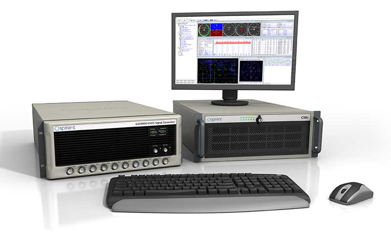
Spirent Communications plc and Qascom have announced a simulation test solution for the Galileo Open Service Navigation Message Authentication (OSNMA) mechanism.
SimOSNMA is designed to work with Spirent’s GNSS simulation platforms to test OSNMA signal conformance, which will bring new levels of robustness for both civilian and commercial GNSS uses.
The GSS9000 test system. (Photo: Spirent)
SimOSNMA provides developers with new simulation tools to test for OSNMA, the security protocol that enables GNSS receivers to verify the authenticity of signals distributed from the Galileo satellite constellation. Designed to combat spoofing, OSNMA ensures the data received is authentic and has not been modified in any way. It is now completing the test phase before its formal launch.
SimOSNMA enables developers to simulate and test OSNMA signals and features, allowing GNSS receiver manufacturers and application developers to accelerate and assure development programs.
Qascom has been a significant contributor to the development of Galileo OSNMA. The company helped create the main test vectors for early testing and led the Position Authenticated Tachograph for OSNMA Launch (PATROL) project, which is the European Union Agency for the Space Program (EUSPA) procurement looking at the implementation of OSNMA into automotive and mass-market GNSS receivers.
“During the development of the first OSNMA receiver prototype, we needed a tool that would allow us to run tests in a controlled and repeatable environment, generate reference data, test corner cases and system events that seldomly occur in reality,” said Carlo Sarto, head of Security Engineering Domain Area. Qascom. “SimOSNMA will allow industries and agencies to speed up the development and qualification of their systems.”
Since the inception of the Galileo project, Spirent has provided crucial simulation and test capabilities to many of the key organizations and projects responsible for development of the European Space Agency (ESA) program.
SimOSNMA is available now for Spirent GSS7000 and GSS9000 platforms.
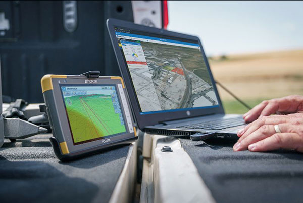
Survey and construction software suite MAGNET7 is now available from Topcon, using cloud-based connectivity to streamline workflows through GNSS receivers and other equipment.
Photo: Topcon
Survey and construction software suite MAGNET 7 is now available from Topcon Positioning Group.
MAGNET7 uses cloud-based connectivity to streamline workflows through GNSS receivers, total stations and other positioning tools and instruments. It addresses common needs to increase productivity, efficiency and profitability levels across the job site.
The software is also designed to improve accuracy while efficiently managing data and collaboration — in real time — with the project team.
Enhancements in the MAGNET7 field version improve 3D model support, reporting and interactivity in working directly on a visual map. Also improved is data handling for large and complex 3D projects.
Productivity features include an ability to connect to the newest version of the Sitelink3D job-site monitoring and management system. This enables office personnel to send machine models via the web portal directly to machines on site.
The new connection also allows access to the Haul Truck app, which dramatically improves efficiency in the mass-haul environment by sending real-time data — including haul volumes and truck locations — directly to the master schedule.
MAGNET7 provides new capability for calculating the International Roughness Index (IRI), a valuable indicator for resurfacing projects. The IRI data exports directly to ProVAL formats, commonly used in the paving industry, to report and validate road-surface smoothness against government guidelines.
Also provided are enhanced terrain-modeling capabilities for surveyors and an overall increase in file-type capability.
Addressing COVID-19
COVID-19-related demands placed on construction and survey professionals underscore the need for comprehensive, integrated software solutions to meet those challenges head on, according to Alok Srivastava, senior director, product management.
“The push to ramp up production levels and increase efficiency, while operating profitably, has never been greater,” Srivastava said. “Our suite — made up of field software, cloud services, tightly integrated office software and third-party integrations — is a key component of our digital ecosystem, all designed to enhance productivity in the field while helping the office efficiently manage the project dataset. It does so by tapping the power of integrated solutions to provide end-to-end workflows, superior data exchange and a far better level of collaboration.
“We’ve long recognized that many of the basic needs and challenges of today’s survey and construction disciplines are similar. With that in mind, this solution provides compatible, comprehensive, connected answers to many of those shared issues.”
“The need for digital connectivity, both on site and between the office and the job site, has never been greater,” Srivastava said. “With the continued push toward digitization in all facets of their jobs, today’s construction and survey professionals regularly risk loss of efficiency — and the financial costs associated with it — due to issues of incompatibility between equipment and systems. This upgrade of the MAGNET suite of productivity solutions takes connected field and office management to a new level, making the long sought-after ‘end-to-end workflow’ a reality while helping projects stay on schedule and under budget.”
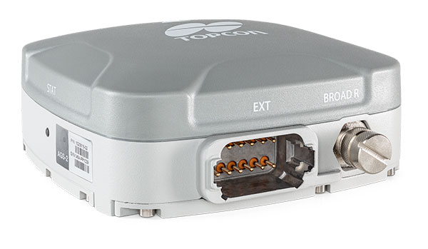
Topcon Agriculture is offering new manual guidance and autosteering receivers — the AGM-1 and AGS-2.
Topcon also launched Topnet Live, a real-time GNSS correction service. Under Topnet Live, the Realpoint service provides greater accuracy and a quick start-up time. Starpoint and Starpoint Pro provide service anywhere on the planet, independent of local networks. Skybridge allows subscribers to combine RTK and PPP correction services.
Accurate positioning is the cornerstone of site-specific management. It is not only required for accurate operations, but expansive data collection, enabling farm professionals to compare different types of information, such as yield, soil type and fertility, for better decision making.
The technology is used for machine operations and all associated tasks where tracking location data is relevant to crop optimization, including soil preparation, seeding, crop care and harvesting.
Photo: Topcon
Topnet Live. To support the range of agricultural applications, the receiver and steering controller uses the new Topnet Live correction services. Plus, with the option of Skybridge, users can maintain network connection during any RTK interruption.
“Topcon receivers are designed to suit virtually any agricultural machine type, make and model,” said Brian Sorbe, vice president of global product solutions. “Equipped with progressive reception and tracking capabilities, with the option of manual guidance or complete autosteering, the receivers are suitable for any size or type of operation. With access to the full range of correction services through the AGS-2, Topcon provides farmers with the right fit for their operation with accuracy on demand. Each unique farming operation may have differing accuracy requirements and this approach will benefit their operation.
“Calibrated to accuracies of within two centimeters, the new correction services provide reliable pass-to-pass precision,” Sorbe said. “Through a constantly improving network and variety of cost-effective subscription models, the service delivers reliable connection stability across the globe. With these new offerings, Topcon continues to offer powerful solutions to suit the variable demands of agriculture.”
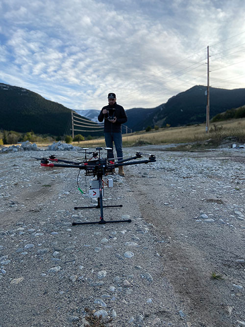
The worlds of UAVs, lidar and surveying overlap, with UAV-based lidar able to shed light on places that are difficult or dangerous to access by other means.
Two questions come into play when deciding whether to use UAV-based lidar for a surveying project. First, do you use a UAV or a manned aircraft? The answer concerns cost, safety and efficiency.
Second, do you use only photogrammetry or photogrammetry plus lidar? This answer depends not only on cost, but payload weight — the single biggest constraint with UAVs. Lidar scanners weigh considerably more than comparable digital cameras.
Far from being mutually exclusive, photogrammetry and lidar are complementary, because digital images make it possible to colorize lidar point clouds, making them easier to interpret. However, the less a UAV’s payload weighs, the greater its flight time per battery charge.
“Most surveyors do not want to be UAV pilots. They want to do their job faster and easier,” said Jake McCay, director of business development at Lidar USA. His company manufactures laser systems — integrated with IMUs and software — for backpack systems, UAVs and helicopters. UAVs make surveyors much more productive and yield more accurate data because they enable them to collect many more points, he said.
UAV versus manned aircraft
Traditionally, data for corridor mapping — such as for power lines and railroads — has been captured with helicopters. However, cost and safety considerations have increasingly shifted the balance toward UAVs, especially hybrid systems that can take off vertically then transition to horizontal flight.
UAVs are also able to fly much lower than manned helicopters, thereby capturing data at much greater resolution.
Nevertheless, manned aircraft still have advantages. “Typically, the break-even is somewhere between 20 km and 40 km on a corridor mapping project if you consider a multi-rotor setup,” said Philipp Amon, business division manager, ULS, Riegl Laser Measurement Systems GmbH. “It takes a week of data acquisition using a UAV and two staff out in the field for what you can normally collect in half a day using a manned aircraft. The costs are almost the same.”
Beyond-visual-line-of-sight (BVLOS) flights are challenging for UAV pilots, because it makes them nervous to lose sight of their expensive platform. Successful BVLOS flights require a dependable and redundant data link. High-quality video transmissions that allow operators to monitor their UAV’s behavior in real time and with no significant latency are also very helpful. “If you do not have all these systems in place, I would not risk it either,” Amon said.
Whether mapping a corridor with a UAV or a manned helicopter, it is best to fly in one direction to the side of the corridor, then return on the other side, capturing data at an oblique angle rather than at nadir. This doubles the point density, enables the correction of any shadows created in a single flight, and — in the case of power lines — enhances safety.
Manned operations require a team of four and a helicopter, as well and a much greater focus on safety than UAVs, said John “JP” Cannon. Cannon is a UAV pilot for PrecisionHawk and team lead of the company’s lidar flight operations, totaling five pilots and more than 10 lidar sensors.
With a manned aerial survey, “You are a little more efficient, but you are burning a lot more logistics to get to that point,” he said. With a UAV, “if you have a properly calibrated sensor and a well-trained pilot, you can get even better data because you can fly lower and slower.” A manned helicopter would require multiple passes to get the same quality of data.
UAVs can collect data even in very remote locations, for later post-processing. (Photo: Lidar USA)
Lidar and photogrammetry
“We combine our lidar systems with all kinds of photogrammetry solutions, such as standard RGB cameras, in both nadir and oblique mounting options,” Amon said. “We also have multi-spectral cameras, hyperspectral cameras, and thermal-imaging sensors in our portfolio, and we offer fully integrated systems that combine all these sensors into one system.”
His customers prefer to use lidar sensors, especially to penetrate vegetation, Amon said. “That is often the most critical part of a survey, especially if you have dense vegetation and are looking for small objects, like in a powerline survey.” While a laser scanner’s multiple returns make it possible to extract surfaces even under vegetation, photogrammetry excels for spot detection.
“If you really want to nail down the error at a specific point, you will need to look at the photogrammetry data. If you want to do surface extraction, classification and remove vegetation, then you are looking for lidar.”
It is generally much faster to post-process lidar data because it does not require georeferencing and correcting thousands of images, but extracting and classifying features takes about the same amount of time.
Lidar “enables utility industry leaders to more effectively manage their networks,” said Cannon. It gives them “a visibility of their assets that photogrammetry just cannot provide, with more robust, precise and consistent data sets.”
Lidar data, he argued, is also less labor-intensive than photogrammetry, because the latter requires constantly tweaking camera features to deal with changes in the environment, such as the amount of light, whereas a well-calibrated lidar scanner “always performs.”
After having tried numerous lidar scanners over the years, PrecisionHawk chose the Riegl miniVUX-1DL, a downward-looking version that can shoot 23˚ off nadir, forward, center and rear. “We use it 20 times a day across multiple platforms.,” Cannon said. “Its data output is consistent and reliable.”
Dissenting voice
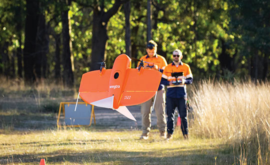
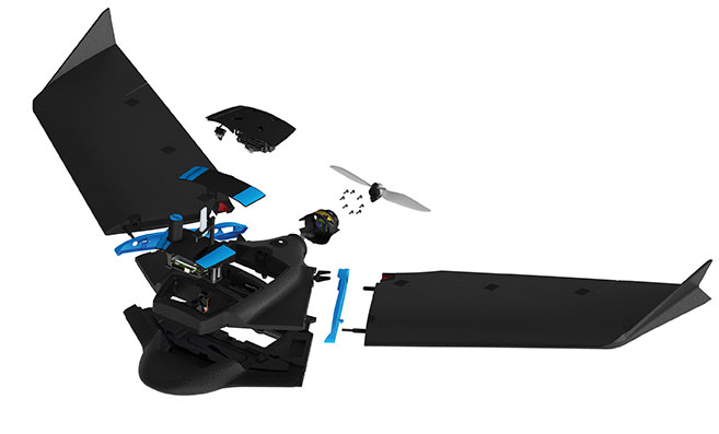
A dissenting voice is that of Wingtra, a manufacturer of vertical take-off and landing UAVs for mapping, survey and mining industry professionals, which has decided not to pursue UAV-based lidar for surveying. “We looked at different use cases, which sensor makes sense for each one, what is already there, and what can be done with manned aircraft and photogrammetry,” explained Andrea Nater, the company’s customer success manager.
“We found that the space for UAV-based lidar systems is very small. There are claims about very high accuracy, but we have not seen that. The point density we have seen so far is limited to 10-cm spacing, so you are really limited in an accurate and dense point cloud, whereas you can have a much higher resolution with photogrammetry.”
While the platform’s absolute position is independent of whether it carries a digital camera or a lidar sensor, “if you have fewer points on the ground, you also have less accuracy,” Nater said. For large areas, UAV-based lidar cannot compete with manned aircraft carrying expensive systems, she said.
“We have also compared manned aircraft with a UAV with low-cost lidar and an RX1 camera. For most use cases you are better off with a high-quality camera rather than a ‘low cost’ lidar. Despite the lidar being more expensive than the camera, the final outputs (point cloud or 3D mesh) generated by photogrammetry have a lower noise level and a higher point density.”
As a bonus, there are more tools for photogrammetry. “The workflows with the many photogrammetry companies are very simple to use, whereas for lidar it is still not as well established and easily adoptable by everyone as it claims to be,” Nater said.
Wingtra’s UAVs perform vertical take off and landing (VTOL), but fly horizontally. New European regulations easing restrictions on flight beyond visual line of sight (BVLOS) make this increasingly common. (Photo: Wingtra)
Positional accuracy
Achieving high positional accuracy with a UAV is challenging, due to the platform’s weight and size limitations for GNSS receivers and antennas. For dedicated UAV missions, Riegl uses the Applanix AV14 and AV18 antennas. The latter can acquire corrections directly from the satellites on L5 without needing a base station, achieving an accuracy of about 5–10 cm.
“We mainly couple our systems with Applanix APX-15 UAV or APX-20 UAV INS/GNSS components,” Amon said. “There are almost no cables needed for an overall system set-up besides power and GPS.” To achieve accuracies of a couple of centimeters, Riegl recommends that users post-process the data. Nearly all of them do, using a single base station in addition to the L-band corrections.
PrecisionHawk uses Riegl lidar equipped with the Trimble Applanix APX20 IMU for direct georeferencing of collected points. “It gives us an absolute and relative positional accuracy of about 2 cm to 5 cm horizontally, with a little bit less vertical accuracy, from 8 cm to 10 cm,” Cannon said. “We couple it with our NovAtel base-station data for PPK corrections. So, everything we do is post-processed, which enables us to focus on safety and efficiency in the field, rather than, say, pulling in RTK corrections and constantly stopping due to jammed signals.”
Lidar USA uses GNSS receivers from “pretty much every manufacturer,” McCay said. “What system we choose depends on the client’s specs. The performance varies greatly. You can buy a $5,000 GNSS-IMU or a $180,000 GNSS-IMU.” Likewise, Lidar USA is not married to a specific platform. “Our system is universal and can be put on several different platforms, as long as they have the payload capacity and have enough clearance for the system underneath.”
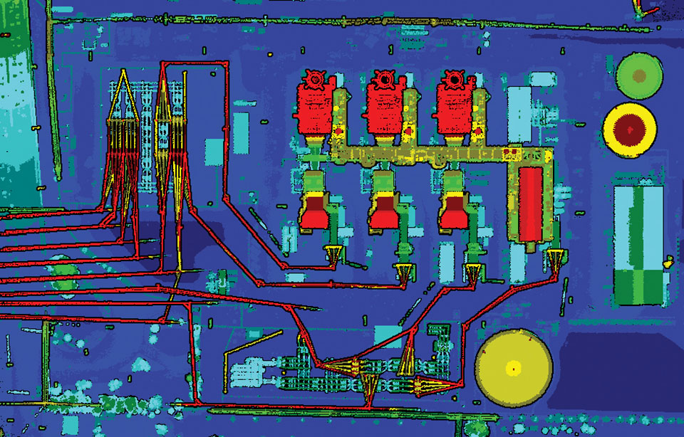
Lidar can reveal the intricate details of an infrastructure, such as this power plant. (Photo: PrecisionHawk)
Multisensory systems
The most common combination of sensors is lidar and RGB. Recently, however, demand for multisensory systems has increased Amon said, especially using hyperspectral integrations and multispectral cameras. “We are using well proven consumer-grade Sony cameras as well as thermal cameras such as the FLIR Tau 2.” The exact mix depends on the customer’s application.
While Riegl sells lidar sensors for customers to use in their own integrations, it also sells complete systems, especially lidar sensors coupled with Applanix INS/GNSS systems and complete turnkey solutions using the systems combined with a platform such as its RiCopter UAV platform.
“We also offer specialized integration kits for the most common UAV platforms, such as the DJI M600,” Amon said. The company also provides software libraries for self-integration, as well as its own data acquisition and postprocessing software.
PrecisionHawk couples its Riegl lidar scanners with Sony A6000 cameras for a dual RGB collection, enabling the company to generate colorized point clouds.
From Nat Geo to Bigfoot
“We have done all sorts of cool projects, from flying for National Geographic in Mexico to looking for Bigfoot in Oregon,” Cannon recalled.
A project for the largest utility provider in the South that has been ongoing for two years involves collecting hundreds of miles of distribution lines across an entire state, including a complete inventory of all the poles.
“These poles have been put up for 100 years. They get put and up and taken down every other day, due to storms and so forth, so who knows what is out there and how accurate it is? Some of the maps they have are from the 1980s.”
Besides accurately locating the poles, the project involves cataloging the assets on each one, such as AT&T equipment, as well as vegetation encroachment and sagging lines between poles. PrecisionHawk executes an average of 25 flights a day for the project, collecting more than one terabyte of lidar and RGB data each month. The data is analyzed using PrecisionAnalytics software.
Lidar USA recently scanned a remote open pit mine in Montana to assess elevation changes from gravel runoff. “There was no cellphone service, and the closest town was probably an hour away,” recalled McCay. “Even in that environment, it is amazing how well our system can perform. The most challenging aspect was that the mine was between two mountains and there were extremely high winds. At one point, the UAV went sideways. Fortunately, our pilot was very experienced, so he was able to correct for that.”
A roundup of recent products in the GNSS and inertial positioning industry from the March 2021 issue of GPS World magazine.
OEM
GNSS Receiver
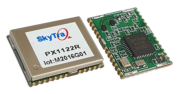
1-cm accurate multi-band receiver
Photo: SkyTraq
The PX1122R is a 12 x 16 millimeter multi-band real-time kinematic (RTK) receiver for centimeter-level-accuracy positioning applications. It uses GPS L1/L2C, Galileo E1/E5b, GLONASS L1/L2 and BeiDou B1I/B2I signals concurrently to maximize positioning availability even in difficult urban environments. A single-chip system-on-chip, the PX1122R is designed to deliver reliable positioning for autonomous unmanned ground or aerial vehicles, the internet of things, and traditional land surveying and precision farming applications. It has an RTK initialization time under 10 seconds and a maximum update rate of 10 Hz. Its update rate provides in-time positioning with a fast response time and improved guidance for fast-moving applications. Moving-base RTK for GNSS precise heading is also supported.
SkyTraq, www.skytraq.com.tw/homesite/
Iridium antennas
Available housed or embedded
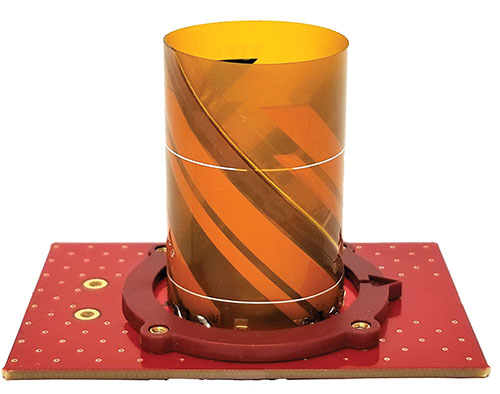
Photo: Tallysman
The housed HC610 and embedded HC610E active Iridium antennas operate in receive-only mode and enable Iridium terminals to be installed tens of meters away from the antenna. The lightweight and compact helical antennas are designed to receive the Iridium Satellite Time and Location (STL) signals. Both antennas are light and compact and feature a precision-tuned helical element that provides an excellent axial ratio and operates without a ground plane. They feature a low-current, low-noise amplifier (LNA) and pre-filter to prevent harmonic interference from high-amplitude signals, such as 700-MHz band LTE and other nearby in-band cellular signals. The housed HC610 weighs 23 grams, is 33 x 54.2 mm, and features an IP67 robust, military-grade plastic enclosure, with a base-mounted male SMA connector and two screw holes for surface attachment. At 10 grams, the embedded HC610E is 27.5 x 38.7 mm and can be installed in a custom enclosure. It provides a base-mounted female MCX connector. An optional embedded helical mounting ring is available to attach the antenna to a flat surface.
Tallysman Wireless, tallysman.com
Receiver front end
Designed for portable receivers
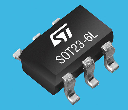
Photo: STMicroelectronics
The BPF8089-01SC6 GNSS receiver front end integrates the impedance-matching and electrostatic discharge protection circuitry typically implemented using discrete components. It provides a 50-ohm matched interface between the receiver’s antenna and LNA, and is ready for plug-and-play with the company’s STA8089 and STA8090 LNAs. It is suitable for use in portable receivers for the GPS, Galileo, GLONASS, BeiDou and QZSS constellations, which can be used in applications such as consumer satellite navigation, radio base stations, drones and tracking of assets or livestock.
STMicroelectronics, st.com
GNSS/INS board
Enhanced with an inertial measurement unit
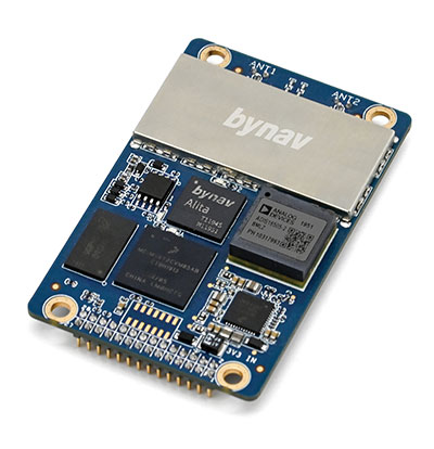
Photo: Bynav
The Bynav A1 is a compact GNSS OEM board with a highly integrated tactical-grade inertial measurement unit (IMU) on board. With Bynav’s new-generation RTK algorithm engine and deeply coupled GNSS/INS algorithm engine, the A1 can provide continuous, reliable high-precision positioning, 3D attitude and velocity to applications such as autonomous driving, robotics, UAVs and mobile mapping. Weighing 25 g and measuring 46 x 71 millimeters, the credit-card-sized A1 is easy to integrate into any system while providing enhanced connection options including serial, Ethernet and CAN.
Bynav Technology, bynav.com
SURVEYING & MAPPING
GNSS/IMU receiver
With tilt compensation
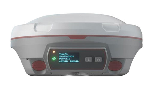
Photo: ComNav
The N5 IMU RTK receiver is user-friendly, with up to 60° tilt compensation ensuring quick measurement and precise position acquisition. A combination of high-end inertial measurement unit (IMU) and advanced GNSS real-time kinematic (RTK) technology, along with ComNav’s core algorithm, ensures high accuracy of less than 2.5 cm, making surveying and mapping in difficult environments easier. The N5 receives all current and future GNSS signals: GPS, GLONASS, BeiDou, Galileo and SBAS. The high-quality OLED display with sunlight readability provides clear viewing and allows users to handle all surveying operations on the screen. A 6800mAh Li-battery allows more than 15 hours of continuous work.
ComNav Technology, www.comnavtech.com
Point creation software
Imports/exports layout files
Photo: Topcon
Topcon Point Manager software is available as a plug-in for Autodesk AutoCAD and Autodesk Revit users in the United States and Canada. It automates point creation and imports and exports layout files to and from a robotic total station. Users will be able to access the solution as a plug-in component to their design package, creating multiple points on building information modeling (BIM) objects and 2D/3D drawings from within the Autodesk environments. Quality assurance and control efforts are improved with point and deviation reports, a likely reduction in on-site personnel, and avoidance of costly errors. Topcon MAGNET users can wirelessly send points to the field for layout, and completed layout files can be sent back to the office to update the model to match as-built conditions.
Topcon, topcon.com
Paving control platform
Directly references design
Screenshot: Trimble
The Trimble Roadworks 3D Paving Control Platform is an accurate, automatic 3D screen control system. It can improve paving productivity and rideability by directly referencing the design rather than a surface or stringline to minimize asphalt usage, reduce waste and overruns, enabling users to finish projects on time and under budget. The Android-based application runs on the 10-inch touchscreen Trimble TD520 display. Operators can personalize the interface to match their workflows, and configurable views make it easier to see the right perspective. The software uses components from Trimble Earthworks, and users can download third-party applications.
Trimble, trimble.com
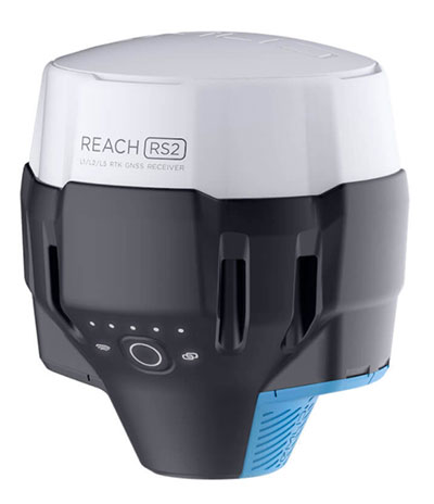
RTK Receiver
Out-of-the-box features
Photo: Emlid
The Reach RS2 is a full-featured multi-band RTK receiver. All of its features are available out of the box, along with a survey app for iOS and Android. The Reach RS2 tracks L1/L2 bands on GPS, GLONASS and BeiDou, and L1/L5 on Galileo, and acquires a fixed solution in seconds. It achieves centimeter-level precision for surveying, mapping and navigation, and maintains robust performance even in challenging conditions. Centimeter accuracy can be achieved on distances up to 60 km in RTK and 100 km in PPK mode. It provides up to 22 hours of autonomous work when logging data and up to 16 hours as a 3G rover, even in cold weather.
Emlid, emlid.com
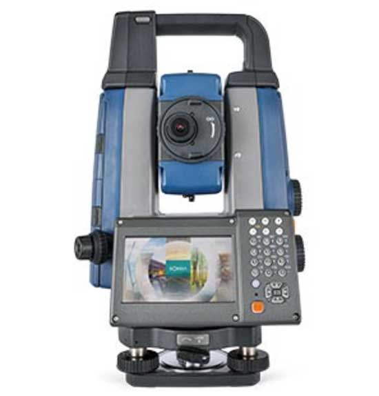
Total stations
Integrate with GNSS
Photo: Sokkia
The iX-1200 and iX-600 robotic total stations are designed to be a part of a workflow solution for survey and layout in construction and infrastructure. They’re engineered for integration with field controllers, software and GNSS receivers. Users can switch to total station measurement integrated with GNSS through an optional upgrade. The stations also can be seamlessly integrated into BIM workflows.
Sokkia, sokkia.com
UAV
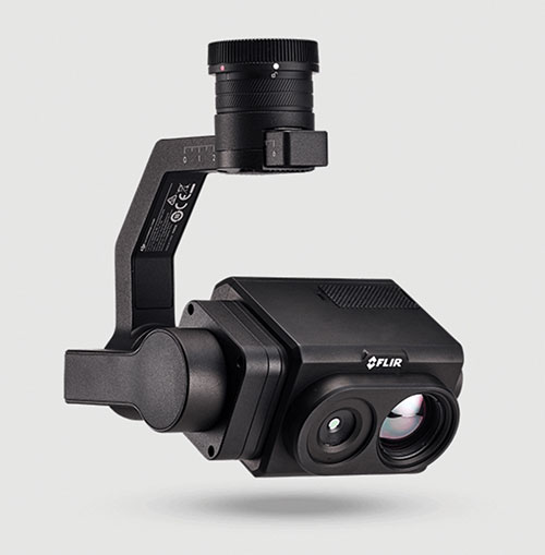
Thermal Payload
High-resolution gimbaled dual-thermal zoom
Photo: FLIR
The FLIR Vue TZ20 plug-and-play payload is fully integrated with the DJI V2 Matrice 200 and 300 series airframes. With 20X zoom capabilities, the FLIR Vue TZ20 provides drone pilots from the public safety and industrial inspection sectors with improved image detail and magnification to assess situations and make critical decisions. The 2x to 20x zoom provides a wide 95-degree field of view for maximum situational awareness, covering large areas in a single flight, or a narrow 18-degree field of view to put more pixels on target when needed. Factory calibrated, the dual 640 × 512 Boson thermal cameras are equipped with expandable infrared video streaming at 30 Hz.
FLIR, flir.com
Fixed-wing UAV
For surveyors, GIS professionals
Photo: SenseFly
The eBee Geo represents the first extension into a new eBee X series of fixed-wing UAVs and is positioned as a cost-effective option for surveyors and GIS professionals who may be unfamiliar with fixed-wing UAV mapping and data collection. With a maximum 45-minute flight time, the eBee Geo can achieve single-flight coverage of 160 ha at 122 m (395 A at 400 ft), suitable for smaller surveying firms and project-based drone service providers. Construction, urban planning and land management users can also benefit from the RGB imaging capabilities of the supplied senseFly S.O.D.A. camera fixed payload, while achieving greater efficiency and absolute accuracy down to 2.5 cm from the eBee Geo’s real-time kinematic (RTK) function. The eBee X is a premium version that offers users the high-precision of on-demand RTK/PPK for achieving absolute accuracy of down to 1.5 cm (0.6 in) without ground control points. Customers also have access to senseFly’s intuitive eMotion flight planning software.
SenseFly, sensefly.com
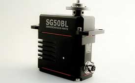
Actuator
With CAN and UAVCAN connectivity
Photo: Hitec Commercial Solutions
The SG50BL actuator includes CAN 2.0 A/B or UAVCAN control options. It is designed with robust steel gears and a high-performance brushless motor. It is capable of operating at 18 to 32 volts. The actuator features a programmable digital circuit with a MOSFET amplifier; a BLDC motor; a magnetic encoder position sensor; five hardened steel gears with low gear backlash (less than .5°); a four ball-bearing supported output shaft; and nine needle bearing supported idlers. It has a rugged anodized aluminum alloy case and an IP68 waterproof rating. The SG50BL also is capable of 360° proportional rotation and has T4131012051-000 TE connectivity. Custom connector options are available.
Hitec Commercial Solutions, hitecnology.com
Smart antennas
Designed for tough environments
Photo: Trimble
The AX940 and AX940i high-precision GNSS smart antennas are designed for a range of high-precision applications, including UAVs. With multi-frequency, multi-constellation support for GPS, Galileo, GLONASS, BeiDou, QZSS and NavIC, the smart antennas can deliver reliable centimeter-level accuracy in a variety of environments. In addition, the Trimble AX940 and AX940i provide reliable, high-accuracy positioning without the constraints of a local base station or cell modem by using Trimble RTX correction services. Built-in inertial sensors on the AX940i allow a tight integration with GNSS observations in the RTK/RTX positioning and orientation engine, providing continuous high-rate low-latency output to guidance and control systems. The Trimble AX940 and AX940i provide flexible interfaces with high-speed data transfer and configuration; simplified integrations reduce development times; and an intuitive 3D graphical web page allows easy input of the lever arm for easier set up.
Topcon Positioning Group is partnering with CyArk, a non-profit organization committed to the conservation of cultural heritage sites around the globe.
Using 3D digital documentation technology, CyArk works to ensure that culturally significant sites can be thoroughly and accurately documented for the benefit of current and future generations. Many of the technologies needed for doing so come from the geospatial world, making the Topcon partnership a welcome one, according to John Ristevski, CEO of CyArk.
“We have supported the documentation of over 200 sites around the world from the Mosque City of Bagerhat in Bangladesh to the iconic statues on Easter Island, but the need for high precision documentation continues to grow and there are many exciting projects yet to come,” he said. “High-precision measurement and documentation of these culturally significant sites is critical for decision making, so we are thrilled to be partnering with Topcon, an industry leader in that area and more.”
The commitment from Topcon includes GNSS receivers, robotic total stations, field controllers, MAGNET software and a subscription to Topnet Live, the company’s real-time GNSS reference network. According to Ulrich Hermanski, executive vice president of Geopositioning for Topcon Positioning Group, having worked alongside CyArk in the past, it was a pleasure to continue to support the organization in this way.
”Our relationship with CyArk dates back to 2015 when we helped them digitally document the Sogi Power Plant, one of Japan’s national industrial historic sites,” Hermanski said. “We quickly recognized and admired the crucial role they are playing in ensuring cultural landmarks of all types are preserved in a digital format. Our expertise — providing precision measurement solutions — blends perfectly with their needs, now and as they move forward.
“One of the first projects on which they plan to use the new solutions is mapping the redwood grove in Big Basin Redwood State Park, in California, an area that suffered severe damage in the recent wildfires,” Hermanski said. “We are pleased to help with this important effort.”
CyArk’s mission, to record, archive and share the world’s most significant cultural heritage sites, stems from a desire to not only save these places digitally but provide critical information to aid in the physical conservation and restoration of the sites today.
“In recent years alone, we’ve seen instances in which culturally-invaluable sites were damaged or lost to arson, terrorism or the effects of climate change,” said Ristevski. “To know that the accurate digital documentation efforts can play a role in rebuilding or reconstruction is a humbling opportunity. We are grateful to have Topcon partnering with us in our efforts.”
After more than five years of hard work by 131 authors from 18 countries, the new book set Position, Navigation, and Timing Technologies in the 21st Century (PNT21) is finally ready to meet readers.
Published by Wiley-IEEE Press, PNT21 offers a uniquely comprehensive coverage of the latest developments in the field of PNT by world-renowned experts. The two-volume set contains 64 chapters organized into six parts.
Position, Navigation, and Timing Technologies in the 21st Century Integrated Satellite Navigation, Sensor Systems, and Civil Applications
Y. Jade Morton, Frank van Diggelen, James J. Spilker Jr. and Bradford W. Parkinson, editors; Sherman Lo and Grace Gao, associate editors Publisher: Wiley-IEEE Press Hardcover Publication Date: January 2021 Vol. 1: ISBN: 978-1-119-45841-8, 1288 Pages Vol 2: ISBN: 978-1-119-45849-4, 912 Pages
Volume 1 focuses on satellite navigation systems, technologies, and applications. It starts with a historical perspective on GPS and other related PNT development.
Part A consists of 12 chapters on fundamentals of and latest developments in global and regional satellite navigation systems (GNSS and RNSS), the need for their coexistence and mutual benefits, signal quality monitoring, satellite orbit and time synchronization, and satellite- and ground-based augmentation systems that provide information to improve the accuracy of navigation solutions.
Part B contains 13 chapters on recent progress in satellite navigation receiver technologies such as vector processing, assisted and high sensitivity GNSS, precise point positioning (PPP) and real time kinematic (RTK) systems, direct position estimation techniques, and GNSS antennas and array signal processing. Also included are the challenges of multipath-rich urban environments, handling spoofing and interference, and ensuring PNT integrity.
Part C finishes the volume with eight chapters on satellite navigation for engineering and scientific applications. A review of global geodesy and reference frames sets the stage for discussions on the broad field of geodetic sciences, followed by a chapter on GNSS-based time and frequency distribution. One chapter each is dedicated to severe weather, ionospheric effects and hazardous event monitoring. Finally, comprehensive treatments of GNSS radio occultation and reflectometry are provided.
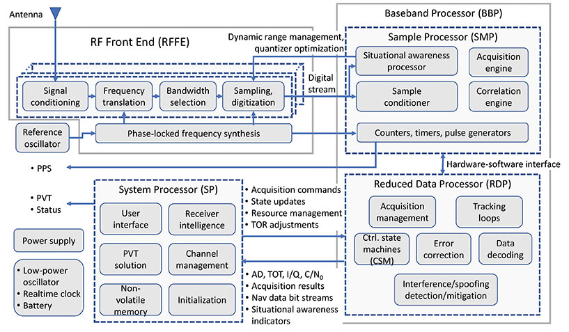
This simplified block diagram of a modern GNSS receiver — one of many illustrations in the book set — appears in Chapter 14, “Fundamentals and Overview of GNSS Receivers,” by Sanjeev Gunawardena and Y. Jade Morton. See excerpt below. (Image: Wiley-IEEE Press)
Volume 2 addresses PNT using alternative signals and sensors and integrated PNT technologies for consumer and commercial applications. An overview chapter provides the motivation and organization of the volume, followed by a chapter on nonlinear estimation methods which are often employed in navigation system modeling and sensor integration.
Part D provides seven chapters devoted to using various radio signals-of-opportunity transmitted from sources on the ground, from aircraft, or from low Earth orbit (LEO) satellites for PNT purposes.
In Part E, eight chapters cover a broad range of non-radio frequency sensors operating in passive and active modes to produce navigation solutions, including MEMS inertial sensors, advances in clock technologies, magnetometers, imaging, lidar, digital photogrammetry, and signals received from celestial bodies.
A tutorial-style chapter on GNSS/INS integration methods is included in Part E. Also included are chapters on the neuroscience of navigation and animal navigation.
Finally, Part F presents a collection of contemporary PNT applications such as surveying and mobile mapping, precision agriculture, wearable systems, automated driving, train control, commercial unmanned aircraft systems, aviation, satellite orbit determination and formation flying, and navigation in the unique Arctic environment.
Table of Contents
Volume 1: Satellite Navigation Systems, Technologies, and Applications
Part A: Satellite Navigation Systems
Part B: Satellite Navigation Technologies
Part C: Satellite Navigation for Engineering and Scientific Applications
Volume 2: Integrated Navigation Systems, Technologies, and Applications
Part D: Position, Navigation, and Timing Using Radio Signals-of-Opportunity
Part E: Position, Navigation, and Timing Using Non-Radio Signals-of-Opportunity
Part F: Position, Navigation, and Timing for Consumer and Commercial Applications
Collective Goal. Because of the diverse authorship and topics covered in PNT21, the chapters were written in a variety of styles. Some offer high-level reviews of progress in specific subject areas, while others are tutorials. A few chapters include links to MatLab or Python example code as well as test data for readers who desire hands-on practice.
The collective goal is to appeal to industry professionals, researchers and academics involved with the science, engineering and application of PNT technologies. The website pnt21book.com provides downloadable code examples, data, homework problems, select high-resolution figures, errata and a way for readers to provide feedback.
Jade Morton is a professor at the University of Colorado Boulder and director of the Colorado Center for Astrodynamics Research (CCAR).
Jade Morton is a professor at the University of Colorado Boulder and director of the Colorado Center for Astrodynamics Research (CCAR).
Excerpt from PNT21
14.1 Anatomy of a GNSS Receiver
Irrespective of the receiver type, the functionality of all GNSS receivers can be broken down into three major blocks: RFFE, baseband processor (BBP), and system processor (SP). In the literature, the term “baseband processor” may be used to refer to the combination of both the BBP and SP defined here. The general anatomy of a GNSS receiver is shown in Figure 14.3.
The RFFE converts the signals induced at one or more antennas into digitized sample streams. Depending on the application and market segment, data rates for these streams may be as low as 0.4 Mbytes/s (e.g. L1 band sampled at 3.5 MSPS and 1-bit sampling in an asset tracking device) to greater than 3 GB/s (e.g. L1 and L2 bands sampled at 60 MSPS and 16 bits across seven elements in an anti-jam military GPS receiver).
The BBP performs digital signal processing to acquire and track GNSS signals present in the digitized sample streams to produce raw GNSS observables for each visible satellite. These observables include time of transmission (TOT), accumulated Doppler Range (ADR), signal quality metrics such as carrier-to-noise density ratio (C/N0), in-phase and quadrature prompt correlator output (I/Q), and raw symbols of a GNSS signal’s broadcast navigation message (which are subsequently decoded). In addition, modern receivers typically perform varying degrees of situational awareness processing to monitor in-band interference such that a level of confidence can be assigned to these raw observables. Some advanced receivers have the ability to identify spoofing signals. Depending on the application, situational awareness outputs may be as rudimentary as the automatic gain control (AGC) voltage used to adjust front-end amplification or as sophisticated as spectrogram, histogram, and sample statistics for all streams evaluated at full sample precision.
The BBP also contains a counter that is driven by a digital clock signal that is phase-locked to the receiver’s reference oscillator. This counter is the basis for the receiver’s clock and is used to generate time-of-reception (TOR) epochs. Raw observables for all satellites in view that lead to range measurements are computed with respect to TOR epochs. Since the receiver clock is based on its reference oscillator, it drifts with respect to GNSS system times. Although possible, the frequency bias, drift, and drift rate of the reference oscillator are typically not adjusted to align with GNSS system time because dynamic adjustment of the oscillator can lead to instabilities. Instead, these parameters are estimated and used to drive a separate adjustable-rate counter that compensates for the reference oscillator errors. This forms the basis for GNSS disciplined oscillators.
It is possible to partition all baseband processing into two categories: sample processor (SMP) and reduced-data processor (RDP). The SMP performs high-rate but simple and algorithmically regular operations which largely comprise multiply-accumulate operations performed at the sample rate. The SMP may also contain configurable timers and pulse/event generators that determine sample processing intervals, as well as output precise timing pulses that are synchronized down to the nanosecond level with respect to GNSS system times (timing accuracy and precision are dependent on the application and market segment). The RDP performs low-rate but algorithmically complex operations. Some representative software functions running within the RDP are illustrated in Figure 14.3.
Bidirectional communications occur between the SMP and RDP at regular timed intervals corresponding to a kilohertz rate. This rate is easily handled by all modern microprocessors. Since these SMP/RDP transactions are time critical, the RDP runs either bare-metal code (i.e. no operating system) or a real-time operating system. The operations within the BBP are inherently parallel and largely independent of each other at the signal processing level. Some coupling occurs, for example‚ in code-carrier aiding, inter-frequency aiding (see Chapter 15), inter-satellite aiding (referred to as vector tracking, described in Chapter 16), and multi-element processing. However, this coupling is typically implemented at higher levels of abstraction. Modern multi-band and multi-constellation receivers are capable of tracking hundreds of GNSS signals simultaneously. To facilitate this highly complex command and control structure – which also needs to be dynamically scalable and adaptive depending on the number of satellites in view, environmental conditions‚ and operating modes – the control architecture is typically layered (i.e. hierarchical). Control at the individual signal acquisition and tracking layers is performed using simple configurable finite state machines (FSMs) whose state transitions are based on signal condition indicators such as code lock, phase lock, C/N0, and code-carrier divergence (CCD). These FSMs operate independently but are typically managed at a high level by the SP.
The SP takes the raw signal observables produced by the BBP and transforms them to the standard GNSS receiver measurements. These measurements include pseudorange (PR), accumulated Doppler range (ADR), carrier phase (CP), carrier Doppler, and C/N0. All modern GNSS receivers also compute position, velocity, and time (PVT) at configurable rates (1 to 100 Hz depending on the receiver type). The SP encodes these in one or more industry-standard data formats for distribution. These formats include Receiver Independent Exchange Format (RINEX), the National Marine Electronics Association (NMEA) format, the Radio Technical Commission for Maritime Services (RTCM) format, and vendor-specific proprietary binary formats.
The SP also performs all high-level functions that include receiver initialization, channel management, and user interface functions. Unlike the BBP, the operations within the SP are generally not time critical. In modern GNSS receivers, the SP is often an embedded computer running an advanced non-real-time operating system. It may also support modern data interfaces (wired USB and Ethernet, or wireless/cellular connectivity) and an advanced graphical user interface with touchscreen support. While too numerous to mention, representative software processes running within the SP are illustrated in Figure 14.3.
Although not shown in Figure 14.3, modern receivers (or the navigation system to which they are interfaced) may also support aiding from external sensors such as inertial measurement units (IMUs), magnetometers, inclinometers, barometers, wheel sensors, RADAR, lidar, infrared (IR), and electro-optical (EO) sensors. This external aiding to GNSS can occur at three levels: loose coupling (position level), tight coupling (measurement level), or ultra-tight coupling (sampled signal processing level). GNSS aiding using various non-GNSS sensors is described in Chapters 43–51 in Volume II, Part E.
As shown in Figure 14.3, a stand-alone GNSS receiver contains battery-powered low-power circuitry to keep track of absolute time while it is turned off. A real-time clock (RTC) driven by a low-power crystal oscillator accomplishes this task. In some cases, this crystal may be the same as the reference oscillator. Knowledge of absolute time, along with the last known location and previously decoded almanac/ephemeris data stored in the receiver’s non-volatile memory, allows it to estimate satellites in view and their Doppler offsets, thereby significantly reducing the TTFF: the time needed to acquire satellites and produce the initial PVT solution. In the case of modern military receivers such as M-Code, or subscription-based services such as the Galileo Public Regulated Service (PRS), the receiver must acquire the cryptographically generated spreading code that may never repeat. In this case, the initial time uncertainty has a significant impact on the acquisition search space and consequently the computational resources consumed by the acquisition engine as well as power consumption. The TTFF can be dramatically reduced when absolute time, the satellites in view, their Doppler frequencies, and ephemerides are sent to the receiver from a nearby reference station via a communications link. This describes the basis of Assisted GNSS (A-GNSS) technology, covered in Chapter 17 of this book.
In some respects, the reference oscillator can be considered the single most important component that affects GNSS receiver performance. Although the PVT solution estimates the deterministic components of the reference oscillator’s frequency error (i.e. short-term bias, drift, and drift rate), the stochastic component cannot be estimated and hence represents additional dynamics that must be tracked (i.e. in addition to satellite motion, user motion, satellite clock motion, and any ionospheric scintillation and multipath). The bandwidth of the carrier tracking loops must be increased to accommodate this close-in phase noise of the reference oscillator. This in turn increases the variance of the range measurements. The reference oscillator is also the only “moving part” in the receiver since it is based on the resonance of a quartz crystal or microelectromechanical systems (MEMS) structure. In addition to microphonics, which are small phase variations that may occur within the RFFE due to external forces (particularly if the RFFE comprises large discrete components), these forces couple through the resonating element leading to shock and vibration sensitivity [6]. Similarly, thermal expansion of the crystal as well as analog components in the RFFE due to changing ambient temperature, unless appropriately compensated or isolated, causes temperature sensitivity. The frequency synthesizer in the RFFE multiplies the oscillator phase noise and dynamics by the ratio of the synthesizer output frequency to the oscillator fundamental frequency, thus placing a significant short-term stability requirement on the reference oscillator. Oscillator short-term stability limits the coherent integration time, which is proportional to the processing gain. Hence, the quality of the reference oscillator directly impacts the recever’s attainable sensitivity (i.e. the minimum observable signal levels) as well as the rate at which it can output statistically independent measurements. Oscillator effects are covered in detail in Chapter 47.
The receiver intelligence process within the SP shown in Figure 14.3 performs functions such as determining what satellites are in view, how best to mitigate any in-band interference (as observed by the situational awareness indicators), dynamically adapting to varying operating conditions, determining the best set of range measurements to use for the PVT solution based on optimum satellite geometry and estimated range error metrics indicated by C/N0 (for signal blockage) and CCD fluctuations (for multipath and ionospheric effects), and many such highly complex decisions. Typically, these high-level functions occur at a lower rate such as 1 Hz or less. To a large degree, the level of sophistication and engineering embedded within the receiver intelligence block, as well as the other low-level control functions determines the receiver’s performance in the real world, as expressed by established figures of merit. These include measurement accuracy, update rate, TTFF, sensitivity, dynamics handling capability, multipath mitigation performance, interference detection and mitigation capability, receiver autonomous integrity monitoring, and fault detection and exclusion (see Chapter 23). In other words, for a given market segment and its associated SWaP-C constraints, the receiver’s hardware and available signal processing capabilities can only do so much. The rest, and quite often the attributes that distinguish it in the marketplace, lies within the hundreds of thousands of person-hours and centuries of combined experience baked into its sophisticated software/firmware.
A shipping container with several pieces of key GNSS and survey instrumentation is bound for the East African country of Rwanda. The equipment, an in-kind donation from Topcon Positioning Group, will be used in support of Bridges to Prosperity (B2P), an organization committed to building trail bridges to improve the lives of people in rural areas worldwide.
Photo: Bridges to Prosperity
According to B2P, almost a billion people around the world lack safe access to critical resources like healthcare, education, or employment due to an impassable river. Building safe, structurally sound trail bridges for people to travel by foot, bicycle, or motorcycle has an immediate, impactful effect on the lives of those in the area.
“We are fortunate that, even with challenges presented by the COVID-19 pandemic, we have been able to implement new safety measures with limited disruption to our building schedule,” said Devin Connell, B2P’s corporate program director. “Right now, our surveying efforts predominantly involve simple equipment such as auto levels and range finders, which can be time consuming when complex survey information is needed. The equipment from Topcon will increase our surveying capabilities, streamline the design process, and support us in building more trail bridges for isolated communities.”
Photo: Bridges to Prosperity
In addition to the instruments — a pair of GNSS receivers, two total stations and data collectors — B2P will have access to the Topcon suite of software products, which will assist both the design process and the transfer of files from the field to their remote office or the engineering team working with them. According to Ron Oberlander, vice president of Topcon Global Professional Services group, however, the company’s role extends well past the equipment itself.
“We are excited to be a contributing part of this program,” he said. “But, in order for B2P to use these solutions to their fullest and increase their overall productivity, a training effort will be needed and we’re already setting plans in place for that to happen.
“In addition to conducting online virtual training sessions with B2P staff, we are making eLearning possible by allowing access to MyTopcon, our company knowledge portal. With these tools, they can gain familiarity with their receiver or total station or use the Topcon software to learn how to collect points — all without having us there. They want to be able to hit the ground running once the equipment arrives and this will help make that happen.”
Connell said that their improved survey capability will help accelerate the company’s bridge building. “We go out and survey a year in advance, looking at as many as 100 different remote sites and, tough as it might be, establish priorities with the local governments. We are looking forward to our continued growth in 2021 and, thanks to the generosity of companies like Topcon, that process will be a much better one.”
New service provides PPP convergence for centimeter-level accuracy on land, air and marine applications around the world
Research from Hexagon’s Autonomy & Positioning division has resulted in breakthrough innovations in precise point positioning (PPP) that enable nearly instant global centimeter-level accuracy. These developments pave the way to bring “RTK from the Sky” performance to worldwide users through correction service products and GNSS receivers from Hexagon.
RTK from the Sky technology provides the quick accuracy of an RTK solution with the high accessibility and availability of PPP. Users will no longer have geographic or regional infrastructure restrictions — they will be free to operate anywhere around the world with the same premium level of positioning performance.
RTK from the Sky technology removes the traditional PPP barrier of long convergence times as well as internet and radio communication limitations, delivering instantaneous convergence anywhere in the world. This breakthrough establishes the foundation for assured positioning with no downtime in marine, agriculture, and autonomous applications.
To achieve these results, there must be masterful attention to detail throughout the entire positioning ecosystem: no errors conveniently cancelled and no errors ignored. All errors are carefully estimated and removed from the final GNSS position faster and more reliably than ever before.
This end-to-end fine-tuning of measurement quality and error mitigation establishes the foundation for RTK from the Sky performance. No matter the location or application, users will be able to rely upon the highest availability and accuracy of corrections anywhere in the world, without the convergence time, Hexagon said.
“In 2020, PPP has become RTK — without the mobility limitations,” said Sandy Kennedy, VP of Innovation at Hexagon’s Autonomy & Positioning division. “RTK from the Sky has been a very satisfying development. To see this kind of positioning performance available anywhere in the world is the realization of the next step of innovation for GNSS.”
RTK from the Sky technology will be the foundation for future correction service products and applications from Hexagon built for diverse applications.
The full GNSS User Technology Report 2020 is available for download. (Cover: GSA)
News from the European GNSS Agency
The European GNSS Agency (GSA) has released its latest GNSS User Technology Report, providing a comprehensive analysis of GNSS trends and developments.
With four GNSS available and more than 100 satellites in operation broadcasting multiple frequencies, the GNSS industry is shifting towards the wide adoption of multifrequency receivers across market segments to meet the diverging user needs of emerging applications.
The report includes contributions from leading GNSS receiver, chipset manufacturers and service providers, and serves as a valuable tool to support planning and decision-making with regards to developing, purchasing and using GNSS technology.
Published biennially since 2016, the User Technology Report has become a point of reference for the GNSS industry, research and policy-makers.
Rapid Evolution
‘’The GNSS industry is evolving at a rapid pace and is shaped by the dynamics of emerging applications and user needs as well as the upgrade of existing and new GNSS and Satellite Based Augmentation Systems (SBAS),” said Rodrigo da Costa, GSA executive director. “The industry has understood the potential of Galileo’s unique features.”
The third edition of the report begins with a chapter devoted to technology trends common to all segments: receiver design, position processing and signal processing. It also discusses protection measures against GNSS jamming and spoofing, such as authentication, including what 5G and other technologies and sensors can do, in combination with GNSS.
With multi-constellation now being the norm, the industry is moving towards the wide adoption of multi-frequency receivers even for usually power- and cost-constrained consumer solutions. The Galileo E5 is becoming the preferred frequency with about 20% of all receiver models in the market already using it.
The report is built around four macro segments defined on the basis of commonalities from a technology point of view:
high volume
safety- and liability-critical
high-accuracy
timing devices and solutions (a new-entry in this edition)
Each chapter starts with the macrosegment characteristics and receiver capabilities, depicts the industry landscape and typical receiver form factor, it then delves into the key current and future drivers and trends, and finishes with the added value of the EGNSS, Galileo and EGNOS, for the macrosegment at stake.
Space Data for Europe
This year editor’s special “Space Data for Europe” sheds light on the role that Copernicus and Galileo play within the European Space Programme in the data management and use, now and in the future. It also provides a vision of major transformations underway within our society and our economy and the benefits expected from this digital transformation, paving the way towards the European Data Strategy and Green Deal.
“Today, Galileo and EGNOS already provide increased capabilities which are being used across a broad range of applications, and are already igniting the next generation of location-based applications. In the future, new services — the Galileo High Accuracy Service (HAS), Galileo Open Service Navigation Message Authentication (OS-NMA) and Commercial Augmentation Service (CAS) — will raise the accuracy and reliability bar even higher, and dramatically enhance positioning, navigation and timing solutions for businesses and citizens.
By bringing insight and understanding into the evolutions of GNSS technology, we are creating opportunities for innovation,” concluded da Costa.
Septentrio, a leader in high-precision GNSS positioning solutions, is offering two open-source resources for its GPS/GNSS module receivers.
The first, ROSaic, is a Robot Operating System (ROS) driver for the mosaic-X5 module as well as other Septentrio GNSS receivers.
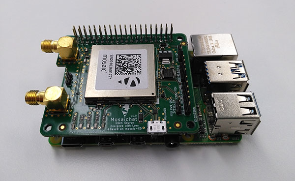
The second project, mosaicHAT, is an open source hardware reference design combining mosaic-X5 with a Raspberry Pi single-board computer.
Both projects facilitate integration of centimeter-level reliable positioning into robotic and other machine automation applications.
Photo: Septentrio
ROSaic driver operates on ROS, a widely used programming environment within the industry as well as academics, commonly used for integrating robot technology and developing advanced robotics and autonomous systems. ROS allows data from numerous sensors to be combined allowing high levels of autonomy.
The mosaicHAT project facilitates accurate and reliable GNSS positioning for robotics and automation on a hardware level. Numerous engineers today use Raspberry Pi for prototyping and initial integrations. The mosaicHAT board is an easy way for integrators to get started with Septentrio’s mosaic-X5 GNSS module.
By plugging mosaicHAT into a compatible Raspberry Pi, users have access to high-accuracy positioning with a high update rate, ideal for machine navigation and control, the company said. The small 56×65 mm board exposes basic interfaces such as USB, serial and general-purpose communication pins. The reference design, footprint and documentation are available for easy board printing or further customization.
“We are excited about both the ROSaic driver and the mosaicHAT being part of the GitHub community and we highly appreciate the initial authors work as well as the future contributors,” said Gustavo Lopez, market access manager at Septentrio. “Both projects are available as open source, thus empowering the community to easily fit autonomous or robotic systems with highly accurate and reliable GNSS positioning technology.”