The European Space Agency (ESA) held its annual Navigation Days on Jan. 26. ESA navigation specialists met with guests from the European Commission, European Global Navigation Satellite Systems Agency and European space companies at ESA’s technical centre in the Netherlands.
With Europe’s Galileo satellite navigation system only one launch away from full global coverage, representatives of the European space industry gathered at ESA’s centre in the Netherlands to discuss the transition towards the future Galileo Second Generation.
Galileo Initial Services began on Dec. 15, 2016, while the constellation in orbit has grown to 22 satellites. An Ariane 5 launch later this year of another quartet will bring the constellation to the point of completion with 24 satellites, plus two orbital spares.
A steady stream of orbital spares, ready to replace satellites reaching the end of their operational lives, is necessary to ensure Galileo continues operating seamlessly. A further 12 satellites were therefore ordered from industry in June 2017.
Paul Verhoef, director of the Galileo Programme addresses the audience at ESA’s annual Navigation Days, held Jan. 26. (Photo: ESA)
Looking further ahead, with the aim of keeping Galileo services as a permanent part of the European and global landscape, a replacement set of Galileo satellites will be required post-2020, serving as transition to a future generation.
The Galileo Second Generation is foreseen to offer improved performance and added features. This is why the European Commission has decided on a Transition Programme, with the European Space Agency (ESA) in charge of its technical definition and implementation.
Together with the European Commission and the European Global Navigation Satellite System Agency, the agency invited leading European space companies to its technical centre in Noordwijk for Navigation Days, held Jan. 26, to discuss Galileo’s future and present short-term plans in relation to this transition programme.
Having started with the ESA European Global Navigation Satellite System Evolutions Programme (EGEP), the system and technology development of Galileo Second Generation is being supported through the EU’s GNSS and Horizon 2020 HSNAV Programmes, with ESA being delegated its technical definition and management of its related implementation.
Eleven Phase-B contracts were signed at the meeting for the Design Phase for both the Galileo Second Generation and the Transition Programme, complementing the more than 50 technology contracts signed in 2017 to prepare for Galileo’s future.
In recent years, innovations have been analysed and predevelopments performed in various technology fields (system, ground, space, receiver technologies) in order to assess their suitability for future Galileo activities, while ensuring backward compatibility and continuity of Galileo Services.
In the next eight months, all major public and private stakeholders will be involved in the detailed assessment of the different evolution scenarios and associated technologies, in order to come to decisions on the Transition Programme baseline for the evolution towards Galileo Second Generation.
Sierra Wireless, a provider of fully integrated device-to-cloud solutions for the Internet of Things (IoT), has introduced multi-mode, low-power wide-area (LPWA) cellular modules.
The modules are targeted at rapidly growing markets in asset tracking and connected industrial equipment, smart cities, healthcare, agriculture and wearables.
AirPrime HL78 modules, featuring Altair Semiconductor’s integrated ALT1250 chipset, deliver power performance that extends the life of battery-operated devices by 5-10X compared to older LTE-M/NB-IoT modules.
The new level of power saving modes was designed for power-constrained IoT applications, and includes improved wake-up and sleep-mode responsiveness, as well as ultra-low sleep-mode power.
The modules also integrate GNSS tracking capability, security and an embedded SIM in a new compact CF3 size (18 x 15 millimeters) that is pin-to-pin compatible with other HL Series modules.
Customers have the flexibility to deploy the same device on global LTE-M (Cat-M1/eMTC) and NB-IoT (Cat-NB1) networks, with support for more than 20 LTE frequency bands in addition to optional 2G fallback.
Built-in security, including HTTPS, secure socket, secure boot and free unlimited firmware over-the-air (FOTA) updates from the AirVantage device management IoT Platform, helps customers ensure HL78 deployments are future proof and secure.
LTE-M and NB-IoT LPWA networks deliver a new class of wireless technology specifically designed for low-power IoT applications. LPWA technologies combine lower cost, broader coverage and better battery life with globally available and secure cellular networks ready to connect hundreds of millions more things to the internet.
“With the HL78 modules, OEMs and system integrators have the most scalable, lowest power module platform to build their global IoT applications on,” said Dan Schieler, senior vice president and general manager, OEM solutions, Sierra Wireless. “And to make it even simpler for our customers, we’ve integrated the SIM and cloud, as well as GNSS and security features, to drive down the size of LPWA connected devices while enhancing tamper resistance and security.”
“More than 690 million LTE-M and NB-IoT connected devices are expected by 2022, and the market needs a low-power, compact embedded module to connect their industrial, smart city, smart home and simpler static sensor applications,” said Dan Shey, managing director and vice president at ABI Research. “With the addition of the HL78 product line, Sierra Wireless has amassed a broad portfolio of low power devices to drive the billions of advanced IoT connections we expect in the next decade.”
“The ability to switch seamlessly between any commercially deployed LTE-M or NB-IoT frequency band gives HL78 customers the flexibility to choose which network they want to deploy their low bandwidth application on. And for those regions where LPWAN coverage is not as widely available, optional 2G fallback ensures their devices stay online,” said Ilan Reingold, vice president, business development and marketing at Altair Semiconductor (a Sony Group company). “Incorporating Altair’s advanced IoT chipset, HL78 devices will also enjoy an extended life of up to 15 years on a single battery.”
The AirPrime HL78 modules are fully compliant with the 3GPP Release 13 standard and are Release-14-ready to support NB2 features in the future.
Sierra Wireless AirPrime HL and WP Series modules are interchangeable across 2G, 3G, 4G and LPWA technologies. They use the CF3 form factor, which is footprint compatible across product lines, providing customers with the option to develop smarter by building their connected IoT product or service on a single module.
HL7800 and HL7802 modules are sampling with lead customers now, with general availability in the third quarter of this year.
Q: How will safety issues raised by increasing autonomous traffic — in the air and on roads — affect the GNSS industry?
Sanchit Agarwal, VP, Field Operations, Nearmap
A: Due to increasing autonomous traffic, the GNSS industry will have to adopt the concepts of collective tracking mechanisms in the shared ecosystem. Inherently, all the cars/drones (rovers) will have the sensors to track the traffic “on-the-fly” and make intelligent navigation decisions, but in case of any system malfunction, the collective tracking of devices can facilitate “social” interactions between the rovers. This will serve as an added layer of security in case an autonomous social member goes rogue!
Zak M. Kassas, Assistant Professor, University of California, Riverside
A: Future autonomous vehicles will demand full situational awareness and extremely reliable, accurate and secure navigation systems. GNSS will not meet the stringent demands of these autonomous vehicles. To address the inevitable situations where GNSS signals become unusable (due to attenuation or interference) or untrustworthy (due to spoofing), receivers should be coupled with sensors such as IMUs, lidar and cameras, and exploit the plenitude of ambient signals of opportunity such as cellular, digital TV and Wi-Fi.
Jonathan Auld, VP of Engineering and Safety Critical Systems, Novatel
A: Safety issues raised by increasing autonomous automotive and airborne traffic will escalate the product development standards and performance requirements of GNSS software, hardware, and correction services used. The GNSS industry is challenged to increase accuracy on lower cost platforms by utilizing multi-frequency, multi-constellation, sensor fusion and precise point positioning. To be able to rely on GNSS in auto-guidance applications, the industry also needs to incorporate GNSS integrity functionalities into our products.
As another holiday season passes us by, it is customary to look back at the year and recall the trends, new products and services, and breakthroughs we experienced with the GNSS environment and its effect on the professional surveyor. While 2017 was not filled with groundbreaking instruments and programming, it did provide a good look at what are going to be trends and gamechangers for the near future. From new innovations on GNSS receivers, new UAV platforms, and geospatial advances, it was also a year that saw location spoofing of shipping vessels, trade relations among super powers being tested, and more opportunities to put satellites into orbit from the private sector. Let us look back at what the surveying community experienced with the GNSS industry:
The constellation scorecard
GNSS continued to expand to all reaches of the globe with enlargement of existing constellations along with introductions of several new ones, (see GPS World magazine “The Almanac,” December 2017). The European satellite system, Galileo, has led the expansion with four (4) new vehicles. This joint venture of the European Commission and the European Space Agency was declared operational at the end of 2016 and looks to keep increasing its coverage in the coming years. For surveyors, this means additional redundancy for our positional data. More confirming redundancy translates into increased confidence in our work product.
Next in numbers of vehicles being sent to space is the Japanese effort named Quasi-Zenith Satellite System (QZSS) and operated by the Japan Aerospace Exploration Agency (JAXA). While their first bird was sent up in 2010, this was the breakout year with three (3) more satellites installed this past year. It is anticipated that the constellation will be operation in 2018 and we can expect most of the GNSS manufacturers to include the positional data from QZSS if they haven’t already built in this capability.
Coming in next are the Chinese with their regional-based system called BeiDou with two (2) more satellites installed in 2017. Their current program is scheduled to have several more vehicles included in the constellation and provide worldwide positional coverage by 2020. With the rapid expansion of China as a world leader, we can anticipate more GNSS developers to work closely with BeiDou as the system becomes more effective on the global stage.
The other world leader, Russia, continues their expansion of GLONASS with the installation of one (1) new satellite in 2017 with plans to upgrade several existing vehicles in the coming years. The inclusion of GLONASS signal reception by survey-grade GNSS receivers has greatly increased the redundancy of data collection, (as mentioned with Galileo). It has also expanded our timeframes in which we can work with reliable positional solutions, thus keeping our downtime to a minimum.
The United States is by no means bringing up the rear in GNSS constellation development but 2017 was a transitional year for the program. A new government administration has led to revisiting our national budget, with the Department of Defense looking to prosper under preliminary plans. While the schedule for constellation expansion have been in place for several years, the installation of Block III satellites has become a higher priority. These satellites will provide higher positional accuracy than previously experienced without any correction signal utilized. This will help the surveyor with better positional accuracies in shorter timeframes and looking forward to its expanded capability.
Once these constellations are operational (with more to come), the ability to record positional locations and attribute data will be greater than ever. A potential challenge to these satellite constellations, however, is the ever-growing fear of potential conflicts between the United States and several countries, including North Korea, Syria, Iran, and Russia. The threat of nuclear war with North Korea could result in our GPS network being shut down to civilians or blocked by an electromagnetic pulse weapon. Cold War tactics with Russia could lead to spoofing or blocking of GLONASS signals that many of our GNSS receivers have become reliant upon. There are alternatives being developed in case our GPS goes away (see “The Day GPS Went Away,” September 2017) but we are several years from having a true secondary option. We will need to keep our fingers crossed we can maintain peace across the globe but do not look forward when something happens and takes our GNSS ability away.
Data mining and the surveyor
One thing that has emerged from 2017 has been the importance of data; where it is housed, how we use it, and what it can tell us about our future endeavors. GNSS has revolutionized the data mining industry with the surveying industry being right in the middle of the fray. Prior articles were published about geolocation (see Geolocation and the surveyor: Looking back to the future) so the rapid expansion of the data collection into most business environments shouldn’t surprise most readers, especially if one reads technical sources like GPS World magazine. The surveying community has watched and experienced the astronomical growth of this data collection in various arenas, none of which was more obvious than the “Geospatial 4.0” initiative at Intergeo 2017 in Berlin, Germany. While summarizing to readers on a trip through the annual conference in the last article (Intergeo 2017: A surveyor’s perspective), it was also here that a bigger picture was coming into focus regarding data and its effect on our world.
While doing homework for this article, the term “Geospatial 4.0” was coined for the 2015 Intergeo conference in Stuttgart, Germany. This term was developed by the conference team regarding the advancing developments in the data world that incorporate geolocation, time, and unlimited information attributes, all while stored in a central location “in the cloud.” This environmental condition exists for most us already, as it is estimated there are three to four billion smartphone users worldwide. The data that is being collected every day is a small part of how our lives and relative actions have become digital snapshots to assist those charged with forecasting and planning of our future cities and environments. Much of this data is being used to advance the places where we live through an initiative called “Smart Cities.” Installation of data collection sensors and control systems in various applications monitor and store information to help make necessary changes to the existing systems. The organizations and municipalities behind this effort are attempting to create better work and home environments with increased efficiency and sustainability.
The professional surveying community plays a big part in the continuing development of geospatial world around us. Our job is not only to collect data for a boundary survey, topographical information for an engineering design, or provide layout assistance for construction; we are also historians in establishing the current positions of required information at a specific point in time. The world around us can move quickly, so providing the precise moment in time when data is collected is sometimes just as important as the location itself. Our role as surveyors becomes even more important as the increased development and implementation of geographical information systems (GIS) emerges within more public and private entities. Where the surveyor previously shunned being included within the collection process and framework of GIS, our profession has become quite efficient at the data acquisition and database maintenance necessary for geospatial success.
The surveyor’s friend in the technical world of geodesy, the geodesist, has not always been an accepted member of the GIS world, either. Once seen as mathematicians stuck in laboratories calculating “perfect world geometric solutions,” the geodesist carries a significant amount of beneficial information to the realm of geospatial data. It has been through their data collection and research that has brought our shifting continents to light and the simple fact our land-based coordinate systems must be modified to change positions as time rolls along. The common theme here is that spatial data comes down to several distinct factors: position, navigation, and time.
PNT (not just another dull government acronym…)
Another big step forward taken in 2017 was the continued implementation of positioning, navigation, and timing, otherwise known as PNT. These three bits of information provide the geographic basis of collected data for any GIS or other environmental study. According to the U.S. Department of Transportation website, here is the definition of PNT:
“…a combination of three distinct, constituent capabilities:
Positioning, the ability to accurately and precisely determine one’s location and orientation two-dimensionally (or three-dimensionally when required) referenced to a standard geodetic system (such as World Geodetic System 1984, or WGS84);
Navigation, the ability to determine current and desired position (relative or absolute) and apply corrections to course, orientation, and speed to attain a desired position anywhere around the world, from sub-surface to surface and from surface to space; and
Timing, the ability to acquire and maintain accurate and precise time from a standard (Coordinated Universal Time, or UTC), anywhere in the world and within user-defined timeliness parameters. Timing also includes time transfer.”
The basis for PNT can be used for any data collection. From fixed monuments utilized by surveyors to any municipal utility installation, the use of PNT now becomes an important part of the GIS database, if not for anything more than simple tracking. By establishing the location of any entity at any given time and comparing its position to an earlier collection, we can determine the navigation of that entity. A good example of PNT and our daily interaction is the satellite navigation systems installed in our phones and vehicles. When we utilize our favorite mapping program on our phone or in our car, we are implementing a PNT system to show us where we are, how fast we are going and help determine how soon we will be getting where we are going. This wonderful practice is being made possible by GNSS data collection and computer processors turning the positional data into useful information.
Surveyors are doing the same thing by the data collection they are performing every day. Any data that is collected by a modern survey instrument is being tagged with two of the main components of PNT; position and time. When the same entity is collected again later, its navigational information can be determined if needed as well. This type of data collection is becoming more apparent with laser scanning and lidar point clouds, as this data can be revisited to determine how much entities within the project area has changed. I foresee a time in the not-to-distant future where much of the Earth is scanned for historical purposes and can be analyzed by future generations for changes. A surveyor could benefit greatly by knowing where a water feature (rivers, creeks, streams, and lake and ocean shores) existed at a specific point in time and how much it has changed over time. Many land boundaries are based upon these water features as natural delineators, so knowing how much title area has changed with the natural movement of a waterway would be very beneficial to the surveyor and how land boundary disputes are handles. Same could be said of buildings and other improvements within developed areas, too. By establishing geospatial data on physical improvements, it could greatly help the surveyor determine historical and future land boundaries by their known location.
The simple fact is that our ability to collect, analyze and retain geospatial information has never been greater than now and only gets better over time. The surveyor now has similar tools to other sciences and technologies, so now is an appropriate time as any to truly embrace geospatial data collection.
UAV’s continuing growth
One market that continues growing at rapid pace is the unmanned aerial vehicle (UAV) sector. 2017 brought more aircraft innovations and expansion of sensors available for a multitude of data collection purposes. This greatly expanding segment of specialized equipment was quite evident at Intergeo 2017, where over 150 UAV vendors were provided their own space solely for the exhibiting as well as an outside arena for demonstrations. While there are other UAV trade shows that rival in the size, the Intergeo show brings the best vehicles, software and ideas for geospatial data collection and imagery directly to the surveyor’s hands.
Other innovations that are taking shape in the UAV world include larger multi-rotor aircraft with increased payloads, vertical takeoff and landing (VTOL) platforms, and a plethora of sensors designed specifically for UAV use. These modules include various methods of lidar for high accuracy scanning, hyperspectral cameras for analyzing plant characteristics, infrared scanners for heat detection, along with camera possibilities that are endless. The main reason to highlight these high-tech applications is simple; these technologies consist of location-based data collection. The surveyor, known professionally as the expert measurer, should make themselves more aware of the rapidly expanding ability to collect data of varying types new to the land surveying field but still relies heavily on accurate and precise measurement methods. The UAV, while still new to many surveyors, is becoming a standard measuring tool in our world. These latest sensors are a result of applying emerging technology for non-traditional surveying clients directly into our wheelhouse. The professional surveyor successfully adapted to new methods and instruments when electronic distance meters, GNSS receivers and laser scanners were introduced, so our profession needs to step up again and take note of what data collection methods and challenges are out there.
Wingtra One in the air. (Photo: Wingtra)
Staying on the subject of surveyors and the UAV, one of the next breakthroughs will be the introduction of affordable aircraft with RTK capability. There are currently several manufacturers of survey-grade UAV aircraft but these are sold at higher price point that is considered out of reach for the typical surveyor. Many have relied on less expensive models in conjunction with their existing RTK receivers to collect physical points or features for use with post-processing software. While not resulting in immediate data for project review, the end product of the post-processed method is quite good and at much lower cost of entry. However, there are times and places where ground control is not available or accessible so flights with photos or scans are not possible. The mainstream UAV manufacturers are taking note of the need for RTK capability and beginning to introduce models with this positional feature, so maybe the tide is turning to lowering the price point for this technology as well. Here is another place the surveyor will need to enter the UAV arena as the long-time RTK expert and utilize the latest technology for expanded data collection purposes. To my fellow surveyors: you’ve been warned, so be ready to get your checkbook out in order to stay competitive.
Survey-grade GNSS receivers
While 2017 wasn’t a breakout year for radically new GNSS technology, it did see its share of minor yet significant improvements. Along with the expansion of existing constellations and preparation for new ones, the technology behind the microprocessor within the GNSS receiver continues to allow for miniaturization and increased speed and accuracy. Several manufacturers are producing survey-grade receivers capable of acquiring hundreds of GNSS signals yet fit in the palm of your hand. Batteries, like most technologies using it, continues to decrease in size yet gain in power-up time. This rapidly shrinking footprint of the GNSS receiver is allowing for placement in more devices and places so the surveyor will need to take advantage of these gains to assist with providing positional and data collection expertise.
A sector of the positioning market that will see rapid increases is the smartphone division. Coupled with the growing GNSS constellations with increasing accuracy signals and more sophisticated computing power programmed specifically for positioning, we will see more smartphones being used for data collection purposes. Google has made significant strides in the customization of the Android operating system to allow for the processing of raw GNSS data to provide positional accuracies beyond the normal smartphone capability. It is safe to say that Apple is likely working on the same type of application for the iOS operating system, so we could see another battle for smartphone supremacy be waged on a highly technical front that surveyors can readily use for their profession.
Another advancement in GNSS technology that will see more in 2018 and beyond will be the use of the inertial measurement unit (IMU) in conjunction with receivers and sensors. Several manufacturers have incorporated IMU’s into their measuring devices to augment the data being collected. The application that has surveyor’s attention is a GNSS receiver with an IMU to record the measurement correlation of the pole tip to the center of the antenna. The IMU has also been configured on various vehicles built for mobile data collection to measure velocities and acceleration to assist with reducing errors within the GNSS measurements by environmental factors. As GNSS receivers continue to evolve and reduce in size, it will also allow for further inclusion of an IMU to help with reduce data errors. Surveyors should take note of these advancements and be prepared to upgrade their equipment and knowledge to stay current with emerging technology and data collection accuracies.
VectorNav’s new Tactical Series includes the VN-110 IMU/AHRS, the VN-210 GPS/INS and the VN-310 dual-antenna GPS/INS.
Into 2018 and beyond…
Some of the items worth watching in the immediate future include:
Autonomous travel
From Elon Musk’s Tesla projects to the Uber/Volvo collaboration with driverless vehicles, autonomous travel will dominate tech news for the next few years. Because these vehicles rely heavily on GNSS positioning in conjunction with road-reading sensors, the focus on the GNSS constellations will stay very much in front of the tech and political worlds. Another portion of the driverless equation is the effective mapping of the roadway system, which come right back into the realm of the surveyor. While we see various mapping vehicles (Google, Apple, and others) out and about digitizing our roadways, the surveyor is the professional entity that is relied upon for the location establishment for existing and future rights-of-way. Our inclusion in mapping these byways is critical to minimizing harm to the public for potential accidents and disasters.
Lightsquared 2.0
The battle over bandwidth several years ago seemed to end with the FCC denying the implementation of ground-based signal amplification by an upstart firm known as Lightsquared. Now with the new administration at the FCC and an atmosphere of deregulation, the firm has rebranded itself as Ligado and is back to try again. Hopefully the same coalition that helped defeat the prior attempt will be back, but with the new ideology running the FCC, all bets are off. The surveyor without GNSS capability (as previous discussed) will mostly be rendered lifeless without it.
Internet of Things (IoT)
Also fighting for bandwidth is a new generation of sensors and monitors being used for a multitude of products and procedures. This movement toward automation is proving to be useful in many environments but is beginning to tax an already overworked data stream. These components are more appropriate in mostly urban areas where broadband coverage is most effective but their implementation in rural America is starting to drive a greater need for more data availability in harder to get places. This push to get more broadband into rural areas will be a wonderful opportunity for those surveyors to complete their projects with similar effectiveness their counterparts in the urban areas already utilize. But the move by the FCC to repeal net neutrality poses a significant threat to that opportunity and equality, so we must wait and see how this plays out as well.
Final thoughts…
While covering a lot of ground here, the main thread is to emphasize the important link between the professional surveyor and the use of GNSS equipment and procedures. Prior to most of the emerging technology, the surveyor was relied solely for boundary determination and not much else. As engineering design became more reliant on detailed topographic surveys, the surveyor increased their responsibility to provide that vital information. As measuring and positional determination has become more complex, the surveyor has adapted to technology and provided that expertise in their duty to protect the public’s interest. Our world is getting more complex every day and we rely on specialized professions for a multitude of tasks. The surveyor can and should be relied upon for tasks discussed herein but making sure both the surveyor and the public knows that is a big key to success. Accurate positioning and reliable measurements requires someone with the knowledge of the subject and technology and the professional surveyor is that someone. To my fellow practitioners; stay involved, advance your education, and continue to be professional.
Views from the top drive this issue of the magazine: personal essays from the directing officers and/or architects of each global satnav system.
The plots of the four articles are the same: what innovations were accomplished in 2017, and what new features to look for in 2018. But the themes differ. If you reflect at the end of each article, try to read between the lines, divine what message seems most important to the author — then distinctions surface.
I’m not suggesting that the directors of each satnav system are trying to accomplish different things. All share the goal of providing the highest quality product and service. I posit that the hands above these guiding hands, atop the top — that is, the national governments paying for each system and directing the directors — do indeed have different priorities. These priorities may produce differing results for industry, markets and users.
The column in November’s GNSS Design & Test e-newsletter elaborates on this hypothesis, as there’s not sufficient space here. Hyper-briefly: the most marked contrast appears between the United States on the one hand and Europe and China on the other. The former appears focused on maintaining the Gold Standard of signals, on beefing up security, and then pretty much letting the market take care of innovation once the space signal hits the Earth’s surface. The other two project clear messages of working closely with industry sectors to encourage and intensify use. For them, GNSS is an economic tool, not merely a political one.
As for my 2018, I will attend both events below, and hope to talk with as many readers as possible there.
Cognizant Autonomous Systems for Safety-Critical Applications Workshop
January 29, 2018 Reston, Virginia
Join a full day of expert presentations and discussions on the opportunities and challenges (technical, commercial, ethical and legal) associated with developing fully autonomous systems that are cognizant and trustworthy for safety-critical applications. Free; sponsored by the Institute of Navigation. Speakers from the National Science Foundation, Department of Transportation, Air Force Research Laboratory, Top Flight Technologies, University of California-Santa Barbara, Santa Clara University, The Ohio State University and more. View more details here.
Munich Satellite Navigation Summit: GNSS — The key to autonomy?
March 5–7, 2018 Munich, Germany
This three-day international conference focuses on the latest developments in satellite-based navigation, gathering high-ranking speakers from industry, science and governments for a broad overview and differing perspectives. Topics include status and real-world results of Galileo; modernization of GPS, GLONASS and BeiDou; developments of QZSS and NavIC; the need for GNSS authentication; civil use of Galileo Public Regulated Service; legal aspects of GNSS; and autonomy within a single GNSS — still possible? Get more details here.
RTX Fast reduces the convergence time — the duration needed to reach full precision accuracy — by up to 98 percent faster than other satellite-delivered correction services, Trimble said.
The service allows customers to realize horizontal positioning accuracy of better than 4 centimeters (1.5 inches) in as fast as one minute. With RTX Fast, farmers, surveyors, geographic information system (GIS) professionals and construction contractors can work faster, improve productivity, minimize input costs and reduce worker fatigue, Trimble added.
New RTX Fast services have recently launched in Switzerland, Slovakia, Northern Italy, Eastern Poland and the Southern regions of Saskatchewan and Manitoba.
In addition, Trimble has a 60 percent larger footprint in the Central U.S., including new coverage in Kentucky and Tennessee.
As the requirement for real-time, absolute positioning grows, Trimble is expanding its RTX Fast coverage to meet the demand both geographically and for the markets it serves, including new emerging applications in vehicle autonomy and location-based services.
The demand for real-time absolute positioning in driving applications continues to rise as Advanced Driver Assistance Systems mature and accuracy requirements become more stringent. RTX Fast provides the network enhancement necessary to deliver fast, high-accuracy RTX corrections for real-time positioning while on the road.
“Trimble RTX technology has been adding value to our core markets since its introduction in 2011. And, now we are demonstrating its capability in new applications such as autonomous driving solutions,” said Patricia Boothe, vice president of Trimble’s Advanced Positioning Division. “We are committed to expanding the reach, use and accessibility of Trimble RTX technology, reinforcing its position as a leading solution for improving GNSS performance.”
VectorNav’s new Tactical Series includes the VN-110 IMU/AHRS, the VN-210 GPS/INS and the VN-310 dual-antenna GPS/INS.
VectorNav Technologies, a provider of inertial navigation solutions, has received accreditation for the AS9100 Rev. D international aerospace standard for its Dallas headquarters.
Based on ISO 9001 standards, the AS9100 standard is a set of quality requirements established by the aerospace industry to satisfy DOD, NASA and Federal Aviation Administration quality requirements.
Founded in 2008, VectorNav is an innovator of miniature, high-performance micro-electro-mechanical systems and GPS/GNSS-based inertial navigation systems.
Recent releases include VectorNav’s surface mount VN-100 IMU/AHRS, VN-200 GPS/INS and VN-300 dual-antenna GNSS/INS, in a new tactical-grade line of inertial navigation systems.
The AS9100 accreditation marks VectorNav’s achievement in demonstrating the highest level of manufacturing, quality and customer service standards. The certification represents the company’s ability and commitment to deliver to its customers worldwide the highest quality miniature inertial navigation systems, from rapid procurement during testing and development to high-volume capacity for integration and production, the company said.
“Earning the AS9100 designation for our Dallas facility demonstrates that we are a highly capable supplier to the global aerospace industry,” said Scott MacDonald, process and quality engineer at VectorNav. “Operating to the highest standards of quality has always been a core principle for us, and this certification reflects our continued commitment to ensure our processes and systems deliver products and services that exceed our customers’ quality, cost, and speed expectations.”
A review of the history of the GLONASS program, its current status and an overview of the plans for the immediate future of the satellite constellation, its navigation signals and the ground support network.
English versions of the GLONASS CDMA interface control documents are now available. See Further Reading.
Richard Langley
On Oct. 12, 1982, the Soviet Union launched the first GLONASS satellite. Whether in reaction to the development of GPS or simply to fulfill the requirement for a system with similar capabilities for its armed forces, the Soviet Union began the development of the Global’naya Navigatsionnaya Sputnikovaya Sistema or Global Navigation Satellite System in 1976 just three years after the start of the GPS program. The first test satellite, code-named Kosmos 1413, was accompanied by two dummy or ballast satellites with the same approximate mass since the Soviet Union was already planning to launch three GLONASS satellites at a time with its powerful rockets to save on launch costs.
But because of launch failures and the characteristically brief lives of the satellites, a further 70 satellites were launched before a fully populated constellation of 24 functioning satellites (providing full operational capability or FOC) was achieved in early 1996. Unfortunately, the full constellation was short-lived. Russia’s economic difficulties following the dismantling of the Soviet Union hurt GLONASS. Funds were not available, and by 2002 the constellation had dropped to as few as seven satellites, with only six available during maintenance operations! But Russia’s fortunes turned around, and with support from the Russian hierarchy, GLONASS was reborn. Longer-lived satellites were launched, as many as six per year, and slowly but surely a full constellation of 24 satellites returned. And on Dec. 8, 2011, FOC was again achieved and has been subsequently more or less maintained — the system has even operated sometimes with in-orbit spares.
While GLONASS-only and survey-grade dual-system GPS/GLONASS receivers have been around for more than a decade, manufacturers took notice of GLONASS’s rebirth and began producing chips and receivers with GLONASS capability for the consumer market. In 2011, Garmin released handheld receivers supporting both GPS and GLONASS. In the same year, various cell-phone manufacturers started offering GLONASS capability with their embedded positioning modules. The early GPS/GLONASS receivers paved the way for the multi-GNSS receivers we have today, with their capability to track not just GPS and GLONASS satellites but those of the European Galileo and Chinese BeiDou systems, as well as those of the Japanese Quasi-Zenith Satellite System (not to mention the satellites of the satellite-based augmentation systems).
I documented the development of GLONASS in this column back in July 1997, and a team of authors from the Joint Stock Company Russian Space Systems discussed the plans for modernizing GLONASS in an April 2011 article. An update is overdue. So, in this article, I will briefly review the history of the GLONASS program, discuss its current status, and overview the plans for the immediate future of the satellite constellation, its navigation signals and the ground support network.
EARLY YEARS, PRESENT DAY
During the Cold War, information about GLONASS was scarce. Apart from the general characteristics of the satellite orbits and the frequencies used for transmitting the navigation signals, the Ministry of Defence of the Soviet Union revealed little else. However, sleuthing by Professor Peter Daly and his students at the University of Leeds provided some details about the signals’ structure. With the advent of glasnost and perestroika, and the eventual demise of the Soviet Union, information about GLONASS became more readily available. Eventually, the Russians released the Interface Control Document (ICD). This document, similar in structure to the Navstar GPS Space Segment/Navigation User Interfaces ICD-GPS-200, describes the system, its components, and the structure of the signal and the navigation message intended for civil use. Its latest version was published in 2016, but so far this version is only publicly available in Russian.
Satellites and Signals. Six models of GLONASS satellites (also known as Uragan, Russian for Hurricane) have been launched so far. Russia (actually the former Soviet Union) launched the first 10 satellites, called Block I, between October 1982 and May 1985. It sent up six Block IIa satellites between May 1985 and September 1986 and 12 Block IIb satellites between Apri1 1987 and May 1988, of which six were lost because of launch-vehicle-related failures. The fourth model was the Block IIv (v is the English transliteration of the Russian alphabet’s third letter). By the end of 2005, the Russians had deployed 60 Block IIvs. Each subsequent satellite generation contained equipment enhancements and also achieved longer lifetimes.
A prototype GLONASS-M (for Modernized) satellite was launched on Dec. 1, 2001, along with two Block IIvs with the first two production GLONASS-M satellites included in the triplet launches of Dec. 10, 2003, and Dec. 26, 2004. Two GLONASS-M satellites were included in the triplet launch of Dec. 25, 2005. The new design offered many improvements, including better onboard electronics, a longer lifetime, an L2 civil signal, and an improved navigation message. Like earlier versions, the GLONASS-M spacecraft still used a pressurized, hermetically sealed cylinder for the electronics.
FIGURE 1. Image from Reshetnev Information Satellite Systems, manufacturer of the GLONASS satellites, celebrating the 35th anniversary of the launch of the first GLONASS satellite in 1982 (“35 years of service to the world”).
All GLONASS satellites launched since December 2005 have been GLONASS-M satellites with the exception of two GLONASS-K1 (sometimes referred to as just GLONASS-K) satellites, launched on Feb. 26, 2011, and Nov. 30, 2014. GLONASS-K1 satellites are markedly different from their predecessors. They are lighter, use an unpressurized housing (similar to that of GPS satellites), have improved clock stability and a longer, 10-year design life. They also include, for the first time, code-division-multiple-access (CDMA) signals on a third frequency accompanying the legacy frequency-division-multiple-access signals (I’ll discuss these shortly). All of the GLONASS satellites have been manufactured by the Joint Stock Company Reshetnev Information Satellite Systems, located in Zheleznogorsk near Krasnoyarsk in central Siberia, and named after Mikhail Fyodorovich Reshetnev, the founding general director and chief designer. The Reshetnev company was formerly known as the Scientific Production Association of Applied Mechanics (Nauchno Proizvodstvennoe Ob”edinenie Prikladnoi Mekaniki or NPO PM). The Roscosmos State Corporation for Space Activities (formerly the Federal Space Agency), commonly known as Roscosmos, is the governmental body responsible for GLONASS.
FIGURE 1 includes artist’s images of the initial GLONASS, GLONASS-M and GLONASS-K1 satellites.
GLONASS satellite orbits are arrayed in three planes, separated from one another in right ascension of ascending node by 120 degrees, with eight satellites in each plane. The satellites within a plane are equally spaced, separated in argument of latitude by 45 degrees. Satellites in adjoining planes are shifted in argument of latitude by 15 degrees. The satellites are placed into nominally circular orbits with a target inclination of 64.8 degrees and semimajor axis of approximately 25,510 kilometers, giving them an orbital period of about 675.8 minutes. These satellites have ground tracks that repeat every 17 orbits or eight sidereal days. The GLONASS orbit planes are numbered 1–3 and contain orbital slots 1–8, 9–16 and 17–24, respectively.
FIGURE 2 shows the status of the constellation on Oct. 17, 2017. The orbital slot number (also called almanac slot) and frequency channel (discussed below) are given in parentheses. The recently launched GLONASS 752 was set healthy on Oct. 16, 2017, resulting in a fully operational 24-satellite constellation. All of the satellites are standard GLONASS-M satellites except for GLONASS 755, which includes a transmitter for the new third frequency, and GLONASS 701K and 702K. These last two are GLONASS-K1 satellites, with 702K operational while 701K is undergoing flight tests. The “K” isn’t part of the official GLONASS number but has been added to avoid ambiguity. A GLONASS-M satellite launched on Dec. 10, 2003, was also called GLONASS 701. Similarly, the International GNSS Service (IGS) refers to GLONASS 701K and 702K as 801 and 802, respectively. IGS also designates GLONASS 751 as GLONASS 851 to prevent confusion with Kosmos 2080, a GLONASS-IIv satellite launched on May 19, 1990, and also called GLONASS 751. And it designates GLONASS 753 as GLONASS 853 to prevent confusion with Kosmos 2140, a GLONASS-IIv satellite launched on April 14, 1991, and also called GLONASS 751.
FIGURE 2. Status of GLONASS constellation on Oct. 17, 2017. A green square identifies the location of a healthy satellite and orange, a test satellite. Orbital slot numbers and frequency channels are given in parentheses.
The satellites have been traditionally launched three at a time by Proton boosters from the Baikonur Cosmodrome near Leninsk in Kazakhstan. However, starting with the launch of the first GLONASS-K1 satellite, several GLONASS satellites have been launched singly on Soyuz rockets from the Plesetsk Cosmodrome north of Moscow.
Unlike GPS and the other GNSSs, GLONASS uses FDMA rather than CDMA for its legacy signals. Originally, the system transmitted the signals within two bands: Ll, 1602.0–1615.5 MHz, and L2, 1246.0–1256.5 MHz, at frequencies spaced by 0.5625 MHz at L1 and by 0.4375 MHz at L2:
L1k = 1602. + 0.5625k (MHz)
L2k = 1246. + 0.4375k (MHz)
This arrangement provided 25 channels, so that each satellite in the full 24-satellite constellation could be assigned a unique frequency (with the remaining channel reserved for testing). Some of the GLONASS transmissions initially caused interference to radio astronomers, who study very weak natural radio emissions in the vicinity of the GLONASS frequencies. Radio astronomers use the frequency bands of 1610.6–1613.8 and 1660–1670 MHz to observe the spectral emissions from hydroxyl radical clouds in interstellar space, and the International Telecommunication Union (ITU) has afforded them primary user status for this spectrum space. Also, ITU has allocated the 1610–1626.5-MHz band to operators of low-Earth-orbiting mobile communications satellites. As a result, the GLONASS authorities decided to reduce the number of frequencies used by the satellites and shift the bands to slightly lower frequencies.
The system now uses only 14 primary frequency channels with k values ranging from –7 to +6, including two channels for testing purposes (currently –5 and –6). (The +7 channel has also been used in the past for testing purposes.) How can 24 satellites get by with only 14 channels? The solution is for antipodal satellites — satellites in the same orbit plane separated by 180 degrees in argument of latitude — to share the same channel. This approach is quite feasible because a user at any location on Earth will never simultaneously receive the signals from such a pair of satellites. The move to the new frequency assignments started in September 1993.
Like the legacy GPS signals, the GLONASS signals include two pseudorandom noise (PRN) ranging codes: ST (for Standartnaya Tochnost or Standard Precision) and VT (for Visokaya Tochnost or High Precision) similar to the GPS C/A- and P-codes, respectively (but at half the chipping rates), modulated onto the L1 and L2 carriers.
As with GPS, GLONASS transmits the high-precision code on both L1 and L2. But, unlike the GPS satellites, the GLONASS standard-precision code has also been transmitted on the L2 frequencies beginning with the GLONASS-M satellites. (A separate civil code, L2C, has been added to the GPS L2 signal transmitted by Block IIR-M and subsequent satellites.) The GLONASS ST code is 511 chips long with a rate of 511 kilochips per second, giving a repetition interval of 1 millisecond. The VT-code is 33,554,432 chips long with a rate of 5.11 megachips per second. The code sequence is truncated to give a repetition interval of 1 second. Unlike GPS satellites, all GLONASS satellites transmit the same codes. They derive signal timing and frequencies from one of the onboard atomic frequency standards (AFSs) operating at 5 MHz. The various GLONASS satellite series since Block II through to the GLONASS-M series have three cesium AFSs on each satellite. The transmitted signals are right-hand circularly polarized, like GPS signals, and have comparable signal strengths.
Navigation Message. Like GPS and the other GNSSs, the GLONASS signals also contain navigation messages providing satellite orbit, clock and other information. Separate 50-bits-per-second navigation messages are modulo-2 added to the ST- and VT-codes. The ST-code message includes satellite clock epoch and rate offsets from GLONASS System Time; the satellite ephemeris given in terms of the satellite position, velocity and acceleration vectors at a reference epoch; and additional information such as synchronization bits, data age, satellite health, offset of GLONASS System Time from Coordinated Universal Time (UTC) as maintained by the National Metrology Institute of the Russian Federation UTC(SU) as part of the State Time and Frequency Service, and almanacs (approximate ephemerides) of all other GLONASS satellites. Note that, unlike GPS System Time, for example, GLONASS System Time has no integer offset from UTC and so leap-second jumps are added to GLONASS System Time simultaneously with those added to UTC. Note, however, that GLONASS System Time is offset by a constant three hours to match Moscow Standard Time (MSK, an abbreviation for Moscow).
The full message lasts 2.5 minutes, and is continuously repeated between ephemeris updates (nominally once every 30 minutes), but the ephemeris and clock information is repeated every 30 seconds.
The GLONASS authorities have not published, at least publicly, details of the VT-code navigation message. It is known, however, that the full message takes 12 minutes and that the ephemeris and clock information are repeated every 10 seconds.
Geodetic System. GLONASS ephemerides are referenced to the Parametry Zemli 1990 (PZ-90 or, in English translation, Parameters of the Earth 1990, PE-90) geodetic system. PZ-90 replaced the Soviet Geodetic System 1985, SGS 85, used by GLONASS until 1993. PZ-90 is a terrestrial reference system with its coordinate frame defined in the same way as that of the International Terrestrial Reference Frame (ITRF). The initial realization of PZ-90 had an accuracy of one or two meters.
However, in an effort to bring the system closer to the ITRF (and GPS’s WGS 84 geodetic reference system), two updates to PZ-90 were carried out. The first update, resulting in PZ-90.02 (referring to 2002), was adopted for GLONASS operations on Sept. 20, 2007, and brought the frame of the broadcast orbits (and hence derived receiver coordinates) closer to ITRF and WGS 84. Another realization, PZ-90.11, adopted on Dec. 31, 2013, reportedly reduced the differences to the sub-centimeter level.
TABLE 1 lists the defining constants and parameters of PZ-90.
TABLE 1. Fundamental geodetic constants and some of the parameters of the PZ-90 geodetic system as used by GLONASS.
The new GLONASS-K satellites transmit additional signals. GLONASS-K1 transmit a CDMA signal on a new L3 frequency (1202.025 MHz), and GLONASS-K2, in addition, will feature CDMA signals on the L1 and L2 frequencies.
FIGURE 3. Circular reflector array on a GLONASS-K1 satellite, surrounding navigation signal inner antenna elements. Photo from Reshetnev Information Satellite Systems.
Control Segment. Similar to GPS and other GNSSs, GLONASS requires a network of ground stations for monitoring and maintaining the satellite constellation and for determining the orbits of the satellites and behavior of their operating AFSs. The tracking network uses stations only within the territory of the former Soviet Union, supplemented with satellite laser ranging stations to help with orbit determination since all GLONASS satellites contain laser reflectors (see FIGURE 3).
Having a non-global network of tracking stations for determining the satellite orbits and AFS behavior results in slightly degraded GLONASS signal-in-space range error (SISRE). Recently, a number of tracking stations overseas have been established in conjunction with the development of the Russian satellite-based augmentation system (SBAS), the System for Differential Correction and Monitoring (SDCM). SDCM will function in a similar fashion to the Wide Area Augmentation System or WAAS, the U.S. SBAS, and the other SBASs in operation. The addition to the tracking network of the overseas SDCM stations, which already includes stations in Antarctica and South America with more stations coming, could help improve SISRE. Roscosmos also uses a global network of IGS and other tracking stations to monitor the health of the GLONASS constellation (see FIGURE 4).
FIGURE 4. Roscosmos global GLONASS satellite health monitoring network with 22 reporting stations on Oct. 18, 2017, between 13:00 and 14:00 MSK.
Performance. SISRE has improved over the years and is currently at the level of about 1 to 2 meters. In part, this is due to the better performance of the on-board AFSs carried by the latest GLONASS-M satellites compared to the first GLONASS-M satellites. Their relative one-day stability has improved from 10-13 to 2.4 × 10⁻¹⁴. FIGURE 5 shows a time series of recent values of SISRE determined by the Information and Analysis Center for Positioning, Navigation and Timing. These error levels can result in pseudorange-based positioning errors using GLONASS broadcast orbits and clocks about a factor of two worse than those provided by GPS — although, at any given instant, positioning accuracy will also be impacted by atmospheric effects and multipath and these could dominate the signal-in-space errors.
FIGURE 5. GLONASS daily root-mean-square signal-in-space range error in meters as determined by the Information and Analysis Center for Positioning, Navigation and Timing.
Much higher positioning accuracies can be obtained using GLONASS orbits and clocks provided by the IGS and its participating analysis centers. This is particularly true if carrier-phase measurements are used instead of or as a supplement to pseudorange measurements. A combination of appropriately weighted GPS and GLONASS measurements has shown to be beneficial in terms of availability, accuracy and efficiency, especially for high-accuracy positioning carried out using the real-time kinematic or RTK approach. Furthermore, the precise point positioning (PPP) technique, based on real-time or post-processing of dual-frequency carrier-phase measurements with precise satellite ephemeris and clock data, has demonstrated that kinematic decimeter-level accuracy is possible using GLONASS data or GLONASS data in combination with GPS data. GLONASS-only static PPP solutions over 24 hours have achieved accuracies at the millimeter level.
Users. The initial uptake of GLONASS by both civil and military users in the former Soviet Union and subsequently in Russia, not to mention outside Russia, was minimal. Prototype GLONASS-only receivers were developed for the military, and foreign GPS/GLONASS receivers were developed by several manufacturers for scientific and other advanced applications. The IGS added a set of GLONASS-tracking receivers to its network in 1998 and has continuously increased the number of such receivers since then. However, consumer use of GLONASS both within and outside Russia has only recently taken off with the development of GLONASS-only and combined GPS/GLONASS chipsets. Such chipsets are now featured in many mobile phones and in handheld GNSS receiver and vehicle navigation units.
NEW AND IMPROVED
As previously mentioned, the GLONASS-K1 satellites include a CDMA signal accompanying the legacy FDMA signals on a new L3 frequency of 1202.025 MHz. The ranging-code chipping rate for the CDMA signal is 10.23 megachips per second with a period of 1 milliseconds. It is modulated onto the carrier using quadrature phase-shift keying (QPSK), with an in-phase data channel and a quadrature pilot channel. The set of possible ranging codes consists of 31 truncated Kasami sequences. (Kasami sequences, introduced by Tadao Kasami, a noted Japanese information theorist, are binary sequences of length 2m – 1 where m is an even integer. These sequences have good cross-correlation values approaching a theoretical lower bound. The Gold codes used in GPS are a special case of Kasami codes.) The full length of these sequences is 214 – 1 = 16,383 symbols, but the ranging code is truncated to a length of N = 10,230 with a period of 1 milliseconds.
The associated navigation message symbols are transmitted at a rate of 100 bits per second with half-rate convolution coding. The so-called navigation message superframe (2 minutes long) will consist of 8 navigation frames (NFs) for 24 regular satellites in the GLONASS first modernization stage and 10 NFs (lasting 2.5 minutes) for 30 satellites in the future. Each NF (15 seconds long) includes 5 strings (3 seconds each). Every NF has a full set of ephemerides for the current satellite and part of the system almanac for three satellites. The full system almanac is broadcast in one superframe.
The lighter, unpressurized K1 satellites feature two cesium and two rubidium AFSs. The relative daily stability of one of the rubidium AFSs on a K1 satellite is reported to be 4 ×10-14. As a result, the SISRE for this satellite is about 1 meter. Plans call for adding a CDMA signal to L2 on future versions of the K1 satellites, dubbed K1+ (see below).
GLONASS-K2 Satellites. These satellites will be heavier than the K1 and K1+ satellites with greater capabilities including a CDMA signal at the GPS/Galileo L1/E1 frequency. Reshetnev ISS will initially build two K2 satellites before going into mass production. It had been planned to transition to the K2 satellites much sooner, only launching the two K1 satellites now in orbit. But apparently plans changed because of the sanctions restricting the delivery of radiation-resistant electronic components from the West.
Now, Reshetnev ISS will build an additional nine GLONASS-K1 satellites. It’s not clear how many of these might be of the K1+ variety. The GLONASS-K1 satellites will now be transition satellites between the existing GLONASS-M satellites (including the half-dozen or so that have been manufactured and stored on the ground for future launch as needed) and the future GLONASS-K2 satellites.
One of the first K2 satellites will host a passive hydrogen maser (PHM) AFS. The PHM has been under development for about a decade, and multiyear ground tests displayed a reliability and one-day stability of 5 × 10-15. It is expected to contribute to future 0.3-meter SISRE.
According to a recent report, GLONASS-K2 satellites will begin flight tests in 2018, with mass production of GLONASS-K2 satellites to begin in the 2019–2020 time frame.
Improved Tracking Networks. The development of the SDCM and its associated tracking network has already been mentioned. The SDCM network stations are equipped with combined GPS/GLONASS dual-frequency receivers, hydrogen maser atomic clocks and direct communication links for real-time data transfer. As mentioned earlier, GLONASS authorities are looking at whether additionally using the SDCM stations for GLONASS orbit and clock determination would significantly enhance the accuracy of the broadcast data.
CONCLUSION
GPS, the oldest GNSS, is continuing to modernize and will soon launch the first Block III or GPS III satellite. Already, GPS Block IIR-M and Block IIF satellites are transmitting new signals. Galileo is fielding modern satellites right from the get go, and BeiDou is about to start launching the operational version of its BeiDou-3 satellites. GLONASS is not to be outdone. It has provided useful positioning, navigation and timing services since at least 1996. While at times the service level has dropped below acceptable levels, it is now a dependable system and, with announced improvements, will be a contender in the future world of multi-GNSS.
FURTHER READING
Official GLONASS Update
“GLONASS Programme Update” by I. Revnivykh presented at the 11th Meeting of the International Committee on Global Navigation Satellite Systems, Sochi, Russia, Nov. 6–11, 2016.
In-depth Description of GLONASS
“GLONASS” by S. Revnivykh, A. Bolkunov, A. Serdyukov and O. Montenbruck, Chapter 8 in Springer Handbook of Global Navigation Satellite Systems, edited by P.J.G. Teunissen and O. Montenbruck, published by Springer International Publishing AG, Cham, Switzerland, 2017.
“GLONASS: Developing Strategies for the Future” by Y. Urlichich, V. Subbotin, G. Stupak, V. Dvorkin, A. Povalyaev and S. Karutin in GPS World, Vol. 22, No. 4, April 2011, pp. 42–49.
“GLONASS: Review and Update” by R.B. Langley in GPS World, Vol. 8, No. 7, July 1997, pp. 46–50. Correction: GPS World, Vol. 8, No. 9, Sept. 1997, p. 71. Available on line:
“GLONASS Spacecraft” by N.L. Johnson in GPS World, Vol. 5, No 11, Nov. 1994, pp. 51–58.
Javad GNSS’ Javad Ashjaee offers a rundown on the company’s Triumph-F1 unmanned aerial vehicle at Intergeo 2017, which took place Sept. 26-28 in Berlin, Germany. According to the company, the Triumph-F1 is a field-tested high-precision geodetic GNSS receiver that includes four battery compartments, four angled documentation cameras and more.
As a U.S. military system, GPS provides all the PNT capabilities they need for defense — until it doesn’t.
Though the accuracies are great and the encrypted signal is resistant to spoofing, its weak signal is very susceptible to jamming. GPS World will host a webinar Nov. 16 to examine ways to augment GPS/GNSS to add resiliency so critical military systems have assured PNT. Registration is free.
Speaker Mikel Miller — Air Force officer (ret.), chief scientist for PNT and instructor — said, “As military operations have evolved over time, three critical technologies have become foundational in synchronized, precision military operations: resilient PNT, resilient communications and resilient cyber. A system-of-systems architecture that integrates and optimizes these three technologies is required to provide trusted and resilient PNT information in GNSS denied/degraded environments.”
Sponsored by precision time company Spectracom, the webinar takes place Nov. 16 at 1 p.m. EST / 10 a.m. PST / 7 p.m. (1900h) Central European Time.
Read about the speakers and their topics below.
Lisa Perdue Product Manager and Applications Engineer, Spectracom
Perdue is an expert in testing critical GPS and GNSS systems. She has trained hundreds of engineers and technicians who are responsible for high-reliability positioning, navigation and timing (PNT) applications. She took a lead role in the development of the first GNSS Vulnerability Test System and speaks widely on the topic at many industry conferences. Perdue is Spectracom product manager at Orolia, where she directs the organization’s GNSS simulation activities and contributes to its entire portfolio of resilient PNT solutions. She has more than 15 years of navigation and RF systems experience, which includes 10 years of service with the U.S. Navy, where she was a certified master training specialist.
Mike Jones
GPS World contributing editor for Defense; Capability Lead for Array Processing, Roke Manor Research
Jones leads the Array Processing group at Roke Manor Research, where he is also a senior consultant engineer. He has an exceptionally broad skill base encompassing sensing, communications, navigation and electronic warfare, and has particular specialist interest in GNSS adaptive antenna systems and direction-finding technology. He has detailed technical knowledge of adaptive antenna GPS systems and was jointly responsible for the development of a number of navigation protection systems using interference cancellation, adaptive beamforming and direction finding. His work is in service on a variety of MoD and DoD airborne platforms around the world. He specializes in the simulation, modeling and hardware implementation of advanced signal processing algorithms, and has led a number of FPGA and ASIC designs for radar, GPS and communications systems. He is also a Fellow of the Royal Institute of Navigation.
Mikel Miller Vice President for PNT Technologies at Integrated Solutions for Systems (IS4S); Former U.S. Air Force Research Laboratory
Miller is building a broad, multi-disciplinary research and development group at IS4S, focused on aspects of PNT and autonomous system science and technology. He began his career as a satellite systems engineer assigned with the U.S. Air Force, holding numerous test, research and development, and program management positions. After earning his Ph.D., he served as an assistant professor of electrical engineering at the Air Force Institute of Technology until his retirement from the Air Force as a lieutenant colonel in 2003. Most recently, he served as the chief scientist for PNT Technologies for the Air Force Research Lab Sensors Directorate. He has authored/co-authored more than 65 journal articles, technical papers and documents, as well as a NATO handbook on navigation technologies. He is a Fellow and past president of the Institute of Navigation (ION) and a past chairman of the Joint Service Data Exchange.
Randy Villahermosa Executive Director, iLAB, The Aerospace Corporation
Villahermosa will speak on research concepts in complementary PNT, including open-source frameworks and the potential role of signals-of-opportunity navigation.
Alan Cameron, Moderator Editor-In-Chief and Publisher, GPS World
Alan Cameron is editor-in-chief and publisher of GPS World magazine, where he has worked since 2000. He also writes the monthly GNSS Design & Test newsletter.
The Riegl VQ-780i waveform processing airborne laser scanner is a high-performance, rugged, lightweight and compact airborne mapping sensor designed for ultra-wide-area mapping and high productivity.
The versatile system is designed for highly efficient data acquisition at low, mid and high altitudes, covering a variety of different airborne laser scanning applications from high-density to ultra-wide-area mapping.
The system provides clutter-free point clouds with high accuracy, excellent vertical target resolution, calibrated reflectance readings and pulse shape deviation for unsurpassed information content on each single measurement.
The Riegl VQ-1560i-DW dual wavelength waveform processing airborne lidar scanning system is for high-point-density mapping applications. The new airborne lidar scanning system offers two lidar channels of different wavelengths: green and infrared (IR).
The two wavelengths allow the acquisition of scan data of complementary information content, delivering two independent reflectance distribution maps and enhanced target characterization, one per laser wavelength.
The VQ-880-GH topo-hydrographic airborne laser scanning system has online waveform processing and full waveform recording. It is a fully integrated airborne laser scanning system for combined hydrographic and topographic surveying with an form factor with reduced height optimized for helicopter integrations.
The system is offered with an integrated and factory-calibrated high-end GNSS/IMU system and up to two cameras. The design allows flexible application of these components to meet specific requirements.
VersaSync is a high-performance GPS master clock and network time server that delivers accurate, software configurable time and frequency signals under all circumstances, including GNSS-denied environments. Its compact size and high level of ruggedization make VersaSync suitable for mobile applications in harsh environments. Its small footprint allows for easy integration of the time and frequency functionality into systems architecture.
VersaSync accommodates an OCXO, a high-performance OCXO or a CSAC oscillator, allowing it to maintain frequency and time accuracy for long periods of GPS/GNSS outage. It can be re-synchronized by an external reference. VersaSync is available with a C/A L1 GPS receiver or with an L1/L2 SAASM receiver. An extension slot accommodates additional timing interfaces.
VersaSync physical inputs and outputs are software configurable and can adapt to various application requirements. I/O pins can be configured as TTL, 10 V pulse, RS232, RS485. This allows VersaSync to provide a high number of outputs of the same type, while still fitting into a small form factor. If the combination of software configurable outputs is not enough, VersaSync can accommodate an option board (within the same form factor), designed to customer requirements.
Because of its high level of ruggedization, VersaSync provides exceptional intrinsic reliability. Strong status monitoring capability, either locally or remotely, allows quick fault diagnoses. An internal, exportable log can be accessed.
Verasync Attributes
Low size, weight and power
Ruggedized (MIL-STD-810G)
High versatility with software configurable inputs/outputs
Design can be efficiently customized to match specific customer requirements
Easy integration due to small footprint and low power consumption
NTP/PTP precise time transfer over Ethernet, including security protocols that prevent network vulnerabilities
Low phase noise 10-MHz frequency distribution
Configurable pulse signals, including IRIG or HaveQuick timecodes
The Simceiver by IP Solutions now features Beidou as a simulated signal with access to full parameters rather than the record and playback function used previously.
The Simceiver is part of the Replicator system, a multi-frequency, multi-system GNSS simulator for advanced research and development, equipment testing and education. It can also function as a recording, playback and signal analysis instrument.
The Replicator is the result of a collaboration with the Japan Aerospace Exploration Agency (JAXA).
Besides the Simceiver hardware unit, components include the ReGen control software for real-time simulation, Streamer control software for recording and playback and ARAMIS software receiver for signal analysis.
The 24-channel Replicator provides real-time generation of GNSS signals, recording and playback of dual-frequency GNSS RF signals, and GNSS RF signal analysis with JAXA COSMODE ionospheric scintillation monitor.
The Replicator offers real-time simulation of dual-frequency GPS, GLONASS, BeiDou or GPS+GLONASS, GPS+BeiDou, GPS+Galileo signals. Comprehensive simulation models include atmosphere, multipath, and more. Also available is signal analysis based on JAXA COSMODE ionospheric scintillation monitor.
Two or more units can be used to simulate, record and playback more signals at the same time. Simulated and recorded signals can be stored in digitized format, analyzed by a MATLAB software receiver and played back as RF at any time.
ReplicatorAdvantages
User defined models with ANSI C API
Real-time simulation
Record and playback
GNSS signal analysis
Upgradable to more features , signals and frequencies for the difference in price.
4- and 7-channel boards for software GNSS receivers
The NT1065_USB3 and NT1065/66_USB3 multi-channel GNSS RF front-end boards are based on NTLab’s RF ICs: NT1065 (4 channels for GPS/GLONASS/Galileo/Beidou/IRNSS/QZSS, L1/L2/L3/L5 bands) and new NT1066 (2 channels for GPS/GLONASS/Galileo/Beidou/IRNSS/QZSS, L1/L2/L3/L5 bands and 1 channel for IRNSS S-band). Both boards support USB3 connection, thus allowing users to process captured satellite signals on a PC or DSP platform.
NT1065_USB3 BOARD
Multi-system multi-band 4-channel GNSS RF front end based on NT1065.
Features
IF bandwidth up to 32MHz for each channel
Acquisition of wideband signals up to 64-MHz (such as Galileo E5) with 2 coherent channels
Built-in 2-bit ADC
USB3 interface (up to 800-Mbit/s)
Ability to connect 4x CRPA
NT1065/66_USB3 BOARD
Multi-system multi-band 7-channel GNSS RF front end based on NT1065 plus new NT1066.
Features
All NT1065_USB3 features, plus:
2 additional L1/L2 GNSS channels
IRNSS S-band channel
Product Support
Both boards are accompanied by comprehensive software and manuals:
GUI for NT1065/66 registers access and USB3 data capture (Windows 7/8/8.1/10 and Linux Ubuntu 16.04 compatible)
Designed to test receivers against current and future signals
Constellator features top-end processing performance and RF quality and offers flexibility in simulation control. It performs fair-weather tests, but also is designed to subject receivers to suboptimal conditions, extreme situations and combinations of errors difficult to access in real-world tests — all of it finely controlled and indefinitely repeatable.
At constellator’s core is software, ensuring that all future constellations, satellites and codes can be handled. Most functional upgrades will then be software-only.
Constellator is used in aerospace and defense (among others) for multi-antenna receiver testing for spacecraft launchers, satellite onboard receiver testing (telecom and observation) and defense UAV receiver testing.
Constellator includes four spatial reference frames and trajectory editors for ground, marine, aerial and spatial motion and import facility. With hardware-in-the-loop, it receives position updates from test rigs in real time and generates corresponding GNSS signals and messages.
Propagation issues can be simulated at individual signal level with different models provided for ionosphere and troposphere.
Satellite error modeling options include orbital errors, onboard clock errors, satellite electronics (front-end) defects, satellite dysfunctions and signal fade, disappearance and “evil waveform” incidents.
Constellator Features
128 channels (extensible) delivering high-quality satellite signals on six distinct frequencies (L and S band)
Hardware-in-the-loop testing at 10- to 100-Hz refresh rates
Extensive simulation options:
Full-time and location control
Receiver trajectories with extreme dynamics
Background noise, interference and jamming/spoofing (two units)
The PwrPak7-E1 contains an Epson G320N micro-electro-mechanical system (MEMS) inertial measurement unit (IMU) to deliver NovAtel SPAN technology in an integrated, single-box solution. It has a powerful OEM7 GNSS engine, integrated MEMS IMU, built in Wi-Fi, onboard NTRIP client and server support and onboard internal storage. The PwrPak7-E1 also has enhanced connection options including serial, USB, CAN and Ethernet.
SPAN Technology
Synchronous Position, Attitude and Navigation (SPAN) technology brings together two different but complementary technologies: GNSS positioning and inertial navigation. The absolute accuracy of GNSS positioning and the stability of IMU gyro and accelerometer measurements are tightly coupled to provide an exceptional 3D navigation solution that is stable and continuously available, even through periods when satellite signals are blocked.
The CAST-5000 produces a single coherent wavefront of GPS RF signals to provide repeatable testing in the laboratory environment or anechoic chamber. The system generates up to seven independent, coherent simulations that reference a single point.With an intercard carrier-phase error of less than one centimeter, the CAST-5000 is extremely accurate.
The system generates a wavefront of GPS when its GPS RF generator cards are operated in a ganged configuration. Each generator card provides a set of GPS satellites coherent with the overall configuration. Several RF generator cards may be utilized together, ensuring phase coherence among the bank of signal generator cards.
The CAST-5000 is the only Controlled Reception Pattern Antenna (CRPA) tester that allows a full end-to-end test of the antenna system. The CRPA antenna, antenna electronics and the GPS receiver can be tested as a unit with or without radiating signals.
CAST-5000 Features
Generates single coherent wavefront of GPS
6 degrees of freedom (DOF) motion generation capability
A next-generation high-precision module for robots, drones
The UM482 is an all-system multi- frequency high-precision heading module with a small footprint. It supports the satellite signals GPS L1/L2, BDS B1/ B2, GLONASS L1/L2, GALI LEO E1/ E5b and SBAS. It is designed for applications such as robot, drone, intelligent drive and mechanical control.
The UM482 GNSS RTK module adopts Unicore’s new-generation Nebulas II chip and UGypsophila real-time kinematic (RTK) algorithm. Based on high-performance data-sharing technology and super-simplified operation system of the Nebulas II chip, the UGypsophila RTK algorithm dramatically optimizes matrix processing. It can involve all satellites from GPS, BDS, GLONASS and Galileo in RTK and heading processing, shorten RTK and heading initialization time to 5 seconds and significantly improve the reliability and accuracy of RTK and heading.
Furthermore, the UM482 integrates the onboard micro-electro-mechanical (MEMS) chip and U-Fusion integrated navigation algorithm, resulting in optimized continuity and reliability of accurate heading and positioning output in tough environments such as city canyons, tunnels and overpasses. Inputs of odometer and external higher performance inertial components are supported.
The HG4930 is a very high-performance micro-electro-mechanical system (MEMS) based inertial measurement unit (IMU) designed to meet the needs of applications across various markets including agriculture, industrial equipment, robotics, survey/mapping, stabilized platforms, transportation, UAVs and UGVs.
With industry-standard communication interfaces, the HG4930 is easily integrated into a variety of architectures. The extremely small size, light weight and low power make the HG4930 ideal for most applications.
The HG4930 includes MEMS gyroscopes and accelerometers. It employs an internal environmental isolation system to attenuate unwanted inputs commonly encountered in real-world applications.
The internal isolation and other proprietary design features ensure the HG4930 is rugged enough to meet the needs of demanding users.
The HG4930 is not ITAR controlled. Its Export Control Classification Number (ECCN) is 7A994.
Example Applications
Aiding a camera pod to track a desired object: For example, a television viewing enhancement systems used in sports broadcasting.
Integration with GPS/GNSS to navigate an object from point A to point B: IMU performance is key; errors grow quickly without GPS/GNSS (such as in forested areas, underwater, dense urban).
Dynamic antenna platform stabilization: IMU measures small perturbations of a platform under motion (including vibration and shock) and feeds those measurements into a control system that then corrects and stabilizes the platform; without an IMU, communication can be degraded or lost.
Robots: Enables robots to navigate indoors with other aiding sources (such as radar or lidar); similar concept to GPS/GNSS aiding.
Supports restricted and classified signals from GPS, Galileo
The Spirent GSS9000 multi-frequency, multi-GNSS RF constellation simulator can simulate signals from all GNSS and regional navigation. The GSS9000 offers a four-fold increase in RF signal iteration rate (SIR) over Spirent’s GSS8000 simulator. The GSS9000 SIR is 1000 Hz (1ms), enabling higher dynamic simulations with more accuracy and fidelity. It includes support for restricted and classified signals from the GPS and Galileo systems as well as advanced capabilities for ultra-high dynamics. It can evaluate resilience of navigation systems to interference and spoofing attacks, and has the flexibility to reconfigure constellations, channels and frequencies between test runs or test cases.
Captures and replays GNSS signals at high resolution
The LabSat 3 Wideband record-and replay-device is small and battery-powered with a removable solid-state disk. It allows users to gather detailed, real-world satellite data and replay the signals on the bench.
Its recording bandwidth of 56 MHz allows for the capture of a wide range of live-sky satellite signals. Depending on the desired bandwidth, recording resolution can be set to 2, 4 or 6 bit. The GNSS frequency guide on the LabSat website shows exactly which signals can be recorded and at which resolution. It also has spare capacity for future planned signals.
Even with this increased capacity over the original LabSat 3, the new simulator remains easy to use: one-touch recording, no connection to PC required, battery powered for up to two hours, and with a removable 1-TB solid-state hard drive that can be replaced in no time, the LabSat 3 Wideband is convenient to use. It measures a compact 167 x 128 x 46 millimeters and weighs 1.2 kilograms.
Live-sky Signals Captured
LabSat 3 Wideband can record and replay the following signals:
Stanford Research Systems (SRS) rubidium frequency standards have excellent aging characteristics, extremely low phase noise and outstanding reliability.
The FS725 benchtop instrument is designed for calibration and research and development (R&D) laboratories, or any application requiring a precision frequency standard, such as metrology laboratories.
The FS725 unit integrates a rubidium oscillator (SRS model PRS10), a low-noise universal AC power supply, and distribution amplifiers in a compact half-width 2U chassis. It provides stable and reliable performance, with an estimated 20-year aging of less than 5 x 10⁻⁹ and a demonstrated rubidium oscillator MTBF (mean time between failures) of more than 200,000 hours.
It has two 10-MHz outputs and one 5-MHz output with exceptionally low phase noise (–130 dBc/Hz at 10-Hz offset) and 1 second Allan Variance (<2 x 10-11). The FS725 can be phase-locked to an external 1-pps reference (like GPS) providing Stratum 1 performance. A 1-pps output is also provided that has less than 1 nanosecond of jitter, and can be set with 1-nanosecond resolution.

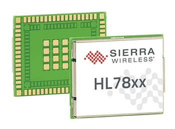


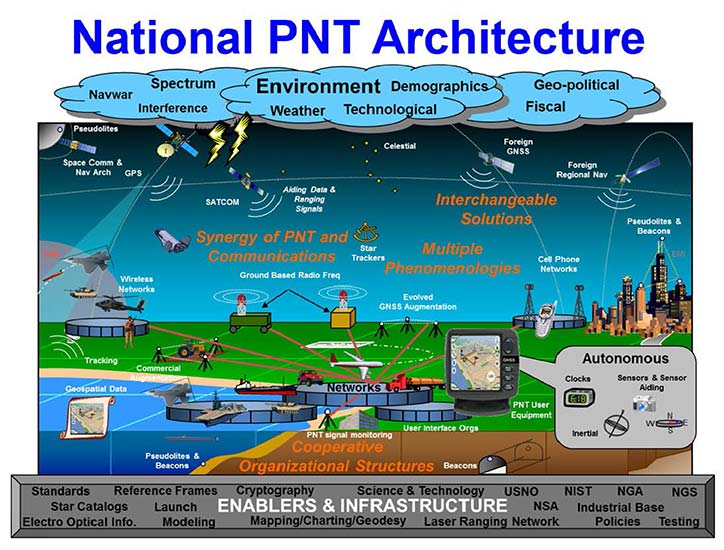


 Mike Jones
 Mikel Miller
 Randy Villahermosa